Full Paper - SMS Lucknow
Full Paper - SMS Lucknow
Full Paper - SMS Lucknow

Create successful ePaper yourself
Turn your PDF publications into a flip-book with our unique Google optimized e-Paper software.
Software Development for Setup Planning of Rotational Part<br />
Sumit Dwivedi* 1 and Shahnawaz Alam 2<br />
ABSTRACT<br />
An innovative approach was developed to solve the problem of setup planning, which is the most critical<br />
problem in process planning for discrete metal parts. Setup planning is the act of preparing detailed work<br />
instructions for setting up a part. The major objective of this research is to improve the performance of CAPP<br />
systems by developing a systematic approach to generate practical setup plans based on tolerance analysis. A<br />
comprehensive literature review on tolerance control in CAPP was conducted. It was found that tolerance chart<br />
analysis, a traditional tolerance control technique, is reactive in nature and can be greatly improved by solving<br />
the problem of setup planning. In order to develop a theoretically sound foundation for tolerance analysis-based<br />
setup planning, the problem of tolerance stack up in NC machining was analyzed in terms of manufacturing<br />
error analysis. Guidelines for setup planning were then developed based on the analysis. To systematically solve<br />
the setup planning problem, a graph theoretical setup planning algorithm for rotational parts was then developed<br />
for automated and integrated setup planning and fixture design. Its efficiency and effectiveness evaluated. The<br />
result is promising. The algorithms were then computerized. A setup planning program was developed under the<br />
Microsoft Windows environment using C.<br />
Keywords: Setup Planning; CAPP; NC machining<br />
1. INTRODUCTION<br />
1.1 Automation and Machining Planning<br />
Machining planning is an important link between<br />
design and manufacturing. It is responsible for<br />
successful and efficient translation of design<br />
information into products. Automated design and<br />
manufacturing with intensive use of computers resulting<br />
in CAD (Computer Aided Design) and CAM<br />
(Computer Aided Manufacturing) respectively have<br />
been important developments of the last three<br />
decades. Recently, over last one decade, automation<br />
of machining planning has emerged as a bridge<br />
between CAD & CAM.<br />
Automated machining has been reported to offer<br />
several advantages including shorter lead time, higher<br />
quality of machined part, lower part cost and more<br />
flexibility in machining planning. The machining<br />
planning as the planning activity performed between<br />
product drawing and actual machining is complex and<br />
ill defined. Machining planning, process planning,<br />
process engineering, and machine routing are some<br />
of the titles given to the same activity.<br />
Machining planning is the systematic determination<br />
of the methods and means by which a product is to<br />
be manufactured economically. The machining<br />
planning involves several or all of the following<br />
functions:<br />
i) Blank Selection: Given the finished part<br />
geometry, a raw material form must be<br />
selected.<br />
ii) Feature Recognition: The final part geometry<br />
is analyzed to identify various features for<br />
machining.<br />
1 * . Sumit Dwivedi Department of Mechanical Engineering, B.N.College of Engineering and Technology, <strong>Lucknow</strong>, Uttar Pradesh, India<br />
Email-smtdwvd@gmail.com<br />
2. Shahnawaz Alam, Ph.D., Department of Mechanical Engineering, Integral University, <strong>Lucknow</strong>, Uttar Pradesh, India, Email-sulehaq@gmail.com<br />
copyright © samriddhi, 2010-2013 S-JPSET : ISSN : 2229-7111, Vol. 4, Issue 1<br />
47
Software Development for Setup Planning of Rotational Part<br />
iii) Operation Selection: For each feature in the<br />
finished part, a set of machining operation,<br />
capable of producing it economically must be<br />
selected.<br />
iv) Operation Sequencing: The order of applying<br />
these operations must be determined. This<br />
sequencing is influenced by several factors such<br />
as accessibility, setup and tolerances.<br />
v) Machine and Cutting Tool Selection: For<br />
each machining operation or a group of<br />
machining operations to be performed, a<br />
machine and a cutting tool must be selected.<br />
vi) Setup Planning: A series of orientations of the<br />
work piece, locating faces and feature to be<br />
produced in each work piece orientation must<br />
be determined.<br />
vii) Picture Design / Selection: For each setup<br />
detailed fixture configuration must be designed,<br />
and / or a suitable set of fixture from the available<br />
list should be selected.<br />
viii) Operation Parameter Selection: Operation<br />
parameter such as feed rate, spindle speed and<br />
depth of cut, must be selected. These can be<br />
selected from machining data hand books.<br />
ix) NC Code Generation and Part<br />
Programming: NC codes to drive NC<br />
machines must be generated<br />
1.2 Importance of Automated Maching Planning<br />
Presently parts, which qualify mass production is<br />
not more than 25% of the total value of metal working<br />
production in all industrialized metal working nations<br />
.One half of the remaining 75% is produced in job or<br />
lots production. The no. of these parts is increasing<br />
each year and their complexity and requirement for<br />
accuracy are also increasing. Social and technological<br />
trends such as demands for customized products,<br />
shorter products lives, higher reliability of products,<br />
along with superior process tolerances and a wider<br />
variety of materials, are some of driving forces behind<br />
the need of smaller batch sizes.<br />
Accordingly industry is leaning toward flexible<br />
manufacturing system (FMS) to meet the demand of<br />
smaller batch sizes and the ever in increasing demand<br />
for productivity improvement.<br />
As FMS advances, less people are seen on shop<br />
floor, but in office next to shop floor, many people<br />
are seen working in machining planning in a labor<br />
intensive way. The manual machining is flexible to<br />
disturbances such as engineering changes and<br />
emergency orders. The flexibility of FMS manual<br />
machining planning has another problem, since process<br />
planning is based on the previous experiences of<br />
planner personal preference, extent of shop knowledge<br />
interpretation of design requirements and other<br />
judgment factors, process plans are often inaccurate,<br />
inconsistent and faulty.<br />
Automating this labor intensive machining planning<br />
offers benefits of more than just saving labor cost of<br />
manual machining planning. More importantly, it offers<br />
the possibility of shorter lead time, higher quality of<br />
machined parts, lower parts cost, scheduling flexibility<br />
and flexibility to disturbances.<br />
1.3 Setup Planning<br />
Setup planning is defined as how to orient and fix<br />
a part so that all the features on the part can be<br />
machined successfully with required tolerance and<br />
surface finish. Setup planning is the critical bridge<br />
between general process planning and detailed<br />
operation planning. It is also the intimate upstream of<br />
fixture planning. In earlier works, setup planning has<br />
been carried out mostly based on tool approach<br />
direction.<br />
The purpose of setup is to locate and fix a part in<br />
a definite manner on a machine tool so that machining<br />
can take place. The theoretically exact point, axis, or<br />
plan used to locate the part is referred to as a setup<br />
datum. When setups and setup datum of a process<br />
plan are not selected properly, a tolerance chart<br />
analysis might find that the process plan cannot<br />
guarantee parts to be made within the specified<br />
tolerance. Hence tolerance information from part<br />
48<br />
S-JPSET : ISSN : 2229-7111, Vol. 4, Issue 1<br />
copyright © samriddhi, 2010-2013
decision should be taken into consideration in setup<br />
planning.<br />
1.4 Objective and Scope of the Present Work<br />
The motivation of this work is automation of<br />
process planning for machining, which is generally<br />
performed manually. In spite of many research efforts<br />
in the past towards the automatic generation of the<br />
plans for machining, setup planning and fixture design<br />
is one of the least studied areas and it remains a major<br />
missing link in automated machining planning.<br />
Integration of process planning with automated<br />
setup planning and fixture design is one of the major<br />
areas, requiring immediate and apt attention of the<br />
researcher in this field. At present, almost most of the<br />
computer aided process planning (CAPP) system do<br />
not have the facility of automatic setup planning and<br />
fixture designing, as this part of CAPP is quite<br />
complicated and carries a lot of bottleneck needed<br />
to be overcome. Hence, automated setup planning<br />
and fixture designing stands as major research issues<br />
in the context of process planning.<br />
In the present work an algorithm based on graph<br />
theory concepts has been developed for automated<br />
and integrated setup planning and fixture design. The<br />
work has been divided into two parts: setup planning<br />
and fixture design which are then integrated. In earlier<br />
works, setup planning has been carried out mostly<br />
based on tool approach direction. Tolerance relations<br />
are taken in to consideration after selection of setup<br />
plan. In this case selected set up plan(s) is (are) not<br />
competent to offer required tolerances then the effort<br />
may go waste. In addition if such selected setups plans<br />
are used then generally machine tools with very high<br />
precision are needed, which directly increase the<br />
production cost. In the present work, tolerance<br />
relation has been considered during selection of setup<br />
planning .Setup planning consists of following task:<br />
1. Setup formation- All the machining features are<br />
grouped together according to their tool approach<br />
direction and tolerance relations.<br />
Sumit Dwivedi and Shahnawaz Alam<br />
2. Datum selection- For each setup, datum surfaces<br />
(primary, secondary, and tertiary) are selected,<br />
3. Setup sequencing- Selected setups are sequenced<br />
on the basis of number of features and tolerance<br />
relations.<br />
This approach gives more comprehensive setup plan.<br />
Basic research issues involve in fixture design are the<br />
selection of locating and clamping positions for a given<br />
work piece along with its setup position(s), in order<br />
to achieve accurate locating, and total restraint of the<br />
work piece, no interference between fixture, work<br />
piece and the cutting tool, and goodness of the design<br />
of the fixture.<br />
Fixture design consists of the following task:-<br />
1. Selection of locating surface,<br />
2. Selection of clamping surface,<br />
3. Selection of locating position,<br />
4. Selection of clamping position<br />
2. PROPOSED ALGORITHM<br />
A. Setup Planning Algorithm For Rotational<br />
Parts<br />
In this section, a setup planning algorithm for<br />
rotational parts is developed and implemented.<br />
Because secondary features such as chamfers and<br />
keyways do not influence setup planning; only primary<br />
features are considered. Primary features of a<br />
rotational part are cylindrical surface and vertical<br />
surface. it is assumed that (1) the total approach<br />
direction of each feature is given ,(2) each setup<br />
requires one (and only one) vertical feature and one<br />
(and only one) cylindrical feature as locating datum,<br />
and (3) a feature may or may not exist on the stock.<br />
The following notations are adopted<br />
n = no. of features within the part<br />
A i<br />
= tool approach direction, defined as follows:<br />
A i<br />
=<br />
1, if feature i can be machined only from the left<br />
2, if feature I can be machined only from the right<br />
0, otherwise<br />
in which i=1, 2,…,n<br />
copyright © samriddhi, 2010-2013 S-JPSET : ISSN : 2229-7111, Vol. 4, Issue 1<br />
E i<br />
feature type, defined as follows:<br />
49
Software Development for Setup Planning of Rotational Part<br />
E i<br />
=<br />
1, if feature i is a vertical feature<br />
2, if feature i is a cylindrical feature<br />
0, otherwise<br />
in which i=1, 2,…, n<br />
S i<br />
stock shape, defined as follows:<br />
S i<br />
=<br />
1, if feature i exits on the stock<br />
0, otherwise<br />
In which i=1, 2, …, n<br />
T= [t ij<br />
] tolerance matrix, defined as follows:<br />
t ij<br />
=<br />
ä ij<br />
, if features i and j have tolerance ä ij<br />
0, otherwise<br />
in which i = 1, 2, …,n<br />
j = 1, 2, …,n,<br />
The algorithm is as follows:<br />
Step 1- Setup Formation<br />
Find t pq<br />
= min [t ij<br />
], in which i = 1, 2, …,n; j =1,2,<br />
…,n; A i<br />
= 0; A j<br />
≠ 0; t ij<br />
≠ 0<br />
If no such t pq<br />
can be found then<br />
for i = 1 to n do<br />
if A i<br />
=0 then<br />
n 1,if A j<br />
=1<br />
let l= Σ X j , in which X j<br />
=<br />
j=1 0, otherwise<br />
n 1,if A j<br />
=2<br />
let r= Σ X j<br />
, in which X j<br />
=<br />
j=1 0, otherwise<br />
if l< r then<br />
let A i<br />
=1<br />
else<br />
go to step 2<br />
else<br />
let A p<br />
=A q<br />
let t pq<br />
=0;t qp<br />
=0<br />
repeat step 1<br />
Step 2-Datum Section<br />
Step 2.0<br />
let t ij<br />
=0 if A i<br />
=A j<br />
, in which i= 1,2,….,n; j=1,2,…,n<br />
let d ij<br />
=0, in which i=1,2,…n; j=1,2,…,n<br />
let T ‘=[t ij<br />
]=T<br />
Step 2.1<br />
find t pq’<br />
=min [t ij<br />
’], in which i=1,2,..n; j=1,2,…..,n; t ij<br />
’≠ 0<br />
if no such t pq<br />
’ can be found then<br />
for i=1 to 2 do<br />
for j=1 to 2do<br />
if d ij<br />
=0 then<br />
find feature w such that A w<br />
=i &E w<br />
=j<br />
let d ij<br />
=1;D ij<br />
=w<br />
go to step 3<br />
else<br />
let t pq<br />
’=0; t qp<br />
’=0<br />
if d ApEp<br />
=0 then<br />
let d ApEp<br />
=1<br />
D ApEp<br />
=p<br />
if d AqEq<br />
=0 then<br />
let d AqEq<br />
=1<br />
D AqEq<br />
=q<br />
2 2<br />
if Σ Σ d ij<br />
=4 then<br />
i=1 j=1<br />
go to step 3<br />
else<br />
go to step 2.1<br />
Step 3- Setup Sequencing<br />
for i=1 to 2 do<br />
for j=1 to 2 do<br />
50<br />
S-JPSET : ISSN : 2229-7111, Vol. 4, Issue 1<br />
copyright © samriddhi, 2010-2013
n<br />
let R ij =<br />
x k,<br />
In which x k =<br />
1,if t Dijk<br />
0<br />
k=1 0, otherwise<br />
find R pq<br />
=max[R ij<br />
]<br />
let Z=<br />
1, if p=2<br />
0, otherwise<br />
Step 4 –Generate Setup Plan Based on Stock<br />
Shape<br />
Let c=0<br />
if S DZ1<br />
1 then<br />
find feature f so that A f<br />
=Z, E f<br />
=1,<br />
&S f<br />
=1<br />
if such a feature cannot be fo und then<br />
let c= 1<br />
else<br />
let D Z1<br />
=f<br />
if S DZ2<br />
1 then<br />
find feature f so that A f<br />
=Z, E f<br />
=2, &<br />
S f<br />
=1<br />
if such a feature cannot be fo und then<br />
let c=1<br />
else<br />
if c1 then<br />
let D Z2<br />
=f<br />
Let S l<br />
= ø ; S r<br />
= ø<br />
Let S L<br />
=S L<br />
U{i} if A i<br />
=1, in which i=1,2,…..,n<br />
Let S R<br />
=S R<br />
U{i} if A i<br />
=2, in which i=1,2,…..,n<br />
if c= 1 then<br />
Machine features D Z1<br />
& D Z2<br />
if z=1 then<br />
Features within S R<br />
are to be machine in the first setup<br />
using features D 11<br />
& D 12<br />
as the locating datum.<br />
Features within S L<br />
are to be machine in the second<br />
setup using features D 21<br />
&D 22<br />
as the locating datum.<br />
else<br />
features within S L<br />
are to be machined in the fir st setup<br />
copyright samriddhi, 2010-2013 S-JPSET : ISSN : 2229-7111, Vol. 4, Issue 1<br />
using features D 21<br />
&D 22<br />
as the locating datum; featur es<br />
with in S R<br />
to be machined in the second setup using<br />
features D 11<br />
&D 12<br />
as the locating datum.<br />
The algorithm can deal with di fferent type of rotational<br />
parts .It was implemented using C++ under the<br />
Microsoft Windows environment .The input for the<br />
software is-<br />
(1) The no. of features<br />
(2) Features type of each feat ures<br />
(3) Tool approach directions o f each feature<br />
(4) Stock shape information<br />
(5) Tolerance information.<br />
The output is a brief descript ion of how to setup the<br />
part.<br />
B. Software of Setup Planning for Rotational<br />
Part<br />
//Software For Setup Planning of Rotational Part//<br />
#include<br />
#include<br />
#include<br />
Sumit Dwivedi and Shahnawaz Alam<br />
void main()<br />
{<br />
int i,j,k,p,q,n,R_max,l,r,f,f_ flag,z,w,c,SL_size,<br />
SR_size,nam, tot;<br />
int A[20],A1[20],E[20],s[20],x[20],<br />
SL[20], SR[20],clam[20];<br />
int d[10][10],D[10][10],R[10][10];<br />
clrscr();<br />
float t[10][10],tt[10][10];<br />
float min_t,min_tt;<br />
int a,b,comp,cmp,ch,g;<br />
float e;<br />
do<br />
{ clrscr();<br />
printf(“\n******************** *********\n\n”);<br />
printf (“Before runnining the software one should have<br />
following informations-\n\n”);<br />
printf (“1. No of features Pre sent in Stock.\n2. Type<br />
of feature (Vertical/Cylindrical/Other).\n3. Tool<br />
approach<br />
51
Software Development for Setup Planning of Rotational Part<br />
Direction for each feature (Left/Right/Both).\n4.<br />
Stock Information (Present/Not present).\n5.<br />
Tolerance<br />
Matrix.\n6. Numbering of LEFT and RIGHT side<br />
features should be in order separately.\n\n”);<br />
printf(“*******************************\n\n”);<br />
printf(“Enter NO. of features present in<br />
stock/job\n”);<br />
scanf (“%d”,&n);<br />
printf (“\nEnter feature type of each<br />
feature.\n (Vertical= 1,Cylindrical= 2,<br />
Other= 0) \n”);<br />
for(i=1;i
printf(“<br />
* FINAL RESULT *\n”);<br />
printf(“\nFeatures present in Stock/Job\n”);<br />
printf(“%d”,n);<br />
printf(“\n\nFeature type of each feature.\n<br />
(Vertical= 1,Cylindrical= 2, Other= 0) \n”);<br />
for(i=1;i
Software Development for Setup Planning of Rotational Part<br />
min_t=t[i][j];<br />
p=i;q=j;<br />
}<br />
}<br />
}<br />
if(min_t==10)<br />
{<br />
for(i=1;i
}<br />
else<br />
{<br />
}<br />
}<br />
if((A[k]==i)&&(E[k]==j))<br />
{<br />
w=k;<br />
if((i==1)&&(j==2))<br />
{<br />
int w1,w2;<br />
w1=(D[i][j-1])+1;<br />
w2=(D[i][j-1])-1;<br />
if((w1==w)||(w2==w))<br />
{<br />
d[i][j]=1;<br />
D[i][j]=w;<br />
break;<br />
}<br />
}<br />
else<br />
{<br />
int w1,w2;<br />
w1=(D[i][j-1])+1;<br />
w2=(D[i][j-1])-1;<br />
if((w1==w)||(w2==w))<br />
{<br />
d[i][j]=1;<br />
D[i][j]=w;<br />
break;<br />
}<br />
}<br />
}<br />
}<br />
goto step3;<br />
}<br />
tt[p][q]=0;tt[q][p]=0;<br />
if(d[A[p]][E[p]]==0)<br />
{<br />
d[A[p]][E[p]]=1;<br />
D[A[p]][E[p]]=p;<br />
}<br />
if(d[A[q]][E[q]]==0)<br />
{<br />
d[A[q]][E[q]]=1;<br />
D[A[q]][E[q]]=q;<br />
}<br />
nam=d[1][1]+d[1][2]+d[2][1]+d[2][2];<br />
if(nam==4)<br />
goto step3;<br />
else<br />
goto step21;<br />
}<br />
Sumit Dwivedi and Shahnawaz Alam<br />
step3:<br />
for(i=1;i
Software Development for Setup Planning of Rotational Part<br />
R_max=R[1][1];<br />
for(i=1;i
{<br />
printf(“\n*****************************\n”);<br />
printf(“\n SETUP 1: “);<br />
printf(“\n Locating Datum- %d %d<br />
\n”,D[1][1],D[1][2]);<br />
if(D[1][2]==0)<br />
{<br />
printf(“\n * NOT POSSIBLE TO LOCATE<br />
THE STOCK/JOB *\n We have to add extra features<br />
(cylindrical/vertical) or \n special Jig & Fixture to get<br />
the desired tolerance limit.\n\n”);<br />
}<br />
printf(“ Machining Features-”);<br />
for(i=1;i
Software Development for Setup Planning of Rotational Part<br />
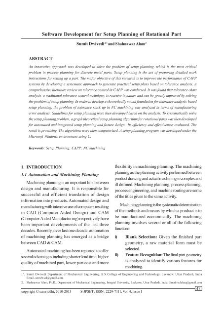
3. EXPERIMENT AND RESULT<br />
3.1 Input and output for rotational part<br />
15 ±0.01<br />
24 ± 0.01<br />
32 ± 0.02<br />
50 ± 0.02<br />
Fig.1. Input and output for rotational part<br />
58<br />
S-JPSET : ISSN : 2229-7111, Vol. 4, Issue 1<br />
copyright samriddhi, 2010-2013
Sumit Dwivedi and Shahnawaz Alam<br />
4. CONCLUSION<br />
In the present work and effort has been done<br />
towards the automation of the machining planning. The<br />
heuristic algorithm .A clamp for each locator has<br />
taken. The features, which are to be machined has<br />
not been selected for clamping.<br />
primary purpose of the work is to automate the setup<br />
REFERENCE<br />
planning and fixture design process to achieve<br />
[1] Halevi, G. and Weill, R.D. 1995. Principles of Process<br />
automatic machining planning.<br />
Planning: A logical approach. Chapman & Hall,<br />
Setup planning is the critical bridge between England.<br />
general process planning and detailed operation<br />
planning. It is also intimate upstream of fixture planning.<br />
Setup planning significantly affects the overall cost &<br />
[2] Mei, J., Zhang, H.C. and Oldham, W.J.B. A neural<br />
network approach for datum selection. Computers<br />
in Industry, 1995, 27, 53-64.<br />
quality of part machining. In the present work graph<br />
theoretic approach has been used for automated setup<br />
planning for rotational parts. The advantages of the<br />
[3] Huang, S.H. and Zhang, H. Tolerance analysis in<br />
setup planning for rotational parts. Journal of<br />
Manufacturing Systems, 1996, 15, 340-350.<br />
graph theoretic approach is that it is a mathematical<br />
[4] Kurian K. Thomas, Gray W. Fischer, “Integrating<br />
CAD/CAM soft ware for process planning<br />
approach & can be easily evaluated, modified &<br />
application”, Journal of Material Processing<br />
computerized. After selection of setups, a heuristic Technology, 61, 1996, PP.87-92.<br />
algorithm has been developed for selection of locating<br />
& clamping surfaces & locating & clamping positions<br />
for a given work piece. Thus the present work can<br />
[5] S.K.Ong and A.Y.C.Nee, “Automating setup<br />
planning in machining operation”, Journal of material<br />
processing technology 63, 1997, PP.151-156.<br />
be summarized as follows:<br />
1. Setups have been formed on the basis of both tool<br />
approach direction & tolerance relation between<br />
[6] Samul H.Huang, “Mathematical formulation for<br />
Automated Set up Planning”, Intelligent CAM<br />
Systems Laboratory, University of Toledo. 11)<br />
features. This approach gives more comprehensive [7] H.C.Wu and T.C.Chag, “Automated setup selection<br />
in feature based process planning” International<br />
setup plan.<br />
Journal of Production research, 1998, Vol.36, NO.3,<br />
2. Datum features have been selected on the basis of PP.695-712.<br />
tolerance requirement between features so that the<br />
specified tolerance requirement can be ensure while<br />
machining. A vertical & a cylindrical surface have<br />
[8] Wang HP, Wysk, RA, A knowledge-based approach<br />
for automated process planning, Int. J.Prod. Res.,<br />
26(6), 999-1014.<br />
been selected as a datum feature for machining<br />
rotational parts, for each setup. This approach<br />
ensures proper location of the part along the axis<br />
(x, y & z).<br />
[9] Shunmugam, M.S., Mahesh, P., Bhaskara Reddy S.V.,<br />
“A method of preliminary planning for rotational<br />
components with C-axis features using genetic<br />
algorithm”, Comput Ind, V 48, p.p. 199–217, 2000<br />
[10] Y.Zhang, W.HU , Y. Rong, David W.Yen, “Graph based<br />
3. Setup has been sequenced on the basis number of<br />
setup planning and tolerance decomposition for<br />
tolerance relation between features of the different<br />
computer aided fixture design”, International Journal<br />
setups, as well as number of features in a particular<br />
setup has been considered.<br />
of Production research, 2001, Vol. 39, No. 14, PP. 3109-<br />
3126.<br />
4. After selection of sequence of setup, position of<br />
locators & clamps has been discussed based on<br />
copyright © samriddhi, 2010-2013 S-JPSET : ISSN : 2229-7111, Vol. 4, Issue 1<br />
59
Software Development for Setup Planning of Rotational Part<br />
[11] Narsingh Deo, “Graph Theory: With applications to<br />
engineering and computer science”, PHI Learning<br />
Private Limited.<br />
[12] ISO 14649 -10:2003 Industrial automation systems<br />
and integration - Physical device control- Data model<br />
for computerized numerical controllers - Part 10:<br />
General process data, ISOTC184/SC 1, May 23, 2003.<br />
[13] Gologlu, Cevdet. Machine capability and fixturing<br />
constraints-imposed automatic machining set-ups<br />
generation. Journal of Materials Processing<br />
Technology, 2004, 148, 83–92.<br />
[14] Deb, S. 2005. Intelligent Computer-Aided Process<br />
Planning for Rotationally Symmetrical Parts Using<br />
Neural Network and Expert System. Ph.D. Thesis,<br />
University of Montreal, Canada.<br />
[15] ) Lan H, Liu R, Zhang C. A multi-agent-based intelligent<br />
STEP-NC controller for CNC machine tools.<br />
International Journal of Production Research<br />
2008;46(14): 3887–907.<br />
60<br />
S-JPSET : ISSN : 2229-7111, Vol. 4, Issue 1<br />
copyright © samriddhi, 2010-2013