UH Series - Mason Technology
UH Series - Mason Technology
UH Series - Mason Technology

You also want an ePaper? Increase the reach of your titles
YUMPU automatically turns print PDFs into web optimized ePapers that Google loves.
C221-E3490C<br />
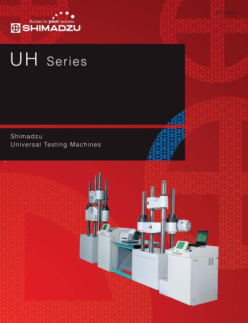
<strong>UH</strong> <strong>Series</strong><br />
Shimadzu<br />
Universal Testing Machines
Acquisition of ISO9001 certification<br />
High-precision force measurement<br />
Various measurement modes<br />
Automatic measurement
<strong>UH</strong> <strong>Series</strong><br />
Shimadzu Universal Testing Machines<br />
As global environmental problems become more and more<br />
serious, materials are required to provide light weight,<br />
high strength and reliability. The <strong>UH</strong> <strong>Series</strong> Shimadzu<br />
Universal Testing Machines are new universal testing<br />
machines that provide various functions enabling more<br />
accurate and simplified measurement of the strength<br />
required for various materials.<br />
The <strong>UH</strong> series enable high-precision<br />
force measurement conforming to<br />
the global standards.<br />
The <strong>UH</strong> series provide various<br />
automatic control programs as<br />
standard functions.<br />
After a specimen is mounted, all<br />
operations can be automatically<br />
performed.<br />
The <strong>UH</strong> series are high-quality<br />
products manufactured in the<br />
factory that acquired the ISO9001<br />
certification.<br />
Contents<br />
P 04 - Features of <strong>UH</strong>-I<br />
P 10 - Operation Unit<br />
P 16 - Specifications Measurement&Control Unit<br />
P 06 - Features of <strong>UH</strong>-FI<br />
P 12 - Software<br />
P 18 - Layout/Installation<br />
P 08 - Control Functions/Configuration<br />
P 14 - Specifications Loading Unit
The <strong>UH</strong>-I series support material strength<br />
tests by providing reliable data.<br />
4
<strong>UH</strong>-I<br />
Shimadzu<br />
Computer-controlled hydraulic servo system<br />
The functions of the <strong>UH</strong>-I series are greatly advanced,<br />
as compared with conventional testing machines.<br />
The large-sized LCD touch panel<br />
greatly simplifies operations and<br />
enhances visibility.<br />
The <strong>UH</strong>-I series provide the graphical interface<br />
that enables various functions<br />
to be operated on the one-touch panel.<br />
During a test, a S-S curve is plotted in real time.<br />
The <strong>UH</strong>-I series newly provide<br />
various automatic control programs<br />
as standard functions.<br />
The metal tensile test control program is provided as a<br />
standard function (conforming to JIS Z2241)<br />
The single test control, cycle test control, high-temperature<br />
tensile test control, stroke speed 3-step switching control<br />
programs are provided as standard functions.<br />
Through the fully-closed loop automatic load control,<br />
the <strong>UH</strong>-I series enable stable and accurate tests.<br />
Force auto-zero and auto-calibration<br />
functions<br />
The <strong>UH</strong>-I series greatly simplify operations by<br />
omitting troublesome adjuster knob operations.<br />
The non-revolving screw rod<br />
improves safety.<br />
A specimen can be safely mounted and<br />
dismounted.<br />
With various application testing<br />
equipment, the <strong>UH</strong>-I series are<br />
applicable to various tests.<br />
Various test jigs, displacement measuring<br />
equipment, atmosphere testing equipment,<br />
test control programs, etc.(See the catalog for<br />
optional accessories.)<br />
With connection to the optional data<br />
processing program,<br />
the <strong>UH</strong>-I series enable high-speed<br />
test data sampling.<br />
The <strong>UH</strong>-I series perform data sampling at a high<br />
speed (5 ms max.) to obtain a true value.<br />
The <strong>UH</strong>-I series can be connected to a personal computer<br />
through the personal computer's standard RS-232C serial<br />
interface. Also, they can be connected to a notebook<br />
computer, saving the required space. (The GP-IB or another<br />
special interface is not necessary.)<br />
5
The <strong>UH</strong>-FI series provide easy-to-operate<br />
front-opening hydraulic grips.<br />
6
<strong>UH</strong>-FI<br />
Shimadzu<br />
Computer-controlled hydraulic servo system<br />
With Highly-efficient, front-opening hydraulic grips<br />
The <strong>UH</strong>-I series advanced functions are further upgraded.<br />
Easy-to-operate front-opening hydraulic grips<br />
The front-opening hydraulic grips using the center hole hydraulic cylinder improves the efficiency in removing a<br />
specimen and scale, and ensures safe operation.<br />
Also, these grips enable even long specimens to be easily mounted.<br />
These grips can be enhanced to the highly-functional, labor-saving model that has the automatic grip face<br />
changing functions.<br />
The compression plate can be easily<br />
mounted anddismounted<br />
A wrench or other tool is not necessary.<br />
A specimen grip position index is<br />
provided<br />
With the specimen grip position index, the grips<br />
can easily and accurately grip a specimen.<br />
The grip face holder is equipped<br />
with a safety stopper<br />
The safety stopper prevents the right and left grip<br />
faces from coming into contact<br />
due to erroneous operation, so that the grip faces<br />
will not be damaged.<br />
The <strong>UH</strong>-FI series can be enhanced<br />
to a fully-automated tensile test<br />
system<br />
All operations including specimen dimension<br />
measurement, specimen feeding<br />
operation, test data processing and chart display<br />
can be automated.<br />
7
High precision control using closed<br />
[ Computer-controlled hydraulic servo system ]<br />
Measurement Control Unit<br />
Lower crosshead<br />
elevating switch<br />
Loading pump<br />
ON/OFF switch<br />
Operation unit<br />
Emergency stop switch<br />
Load control knob<br />
Control Functions<br />
(1) Constant-speed control<br />
Stroke/Force/Strain<br />
(2) Constant-speed control -><br />
Hold control<br />
Stroke/Force/Strain<br />
(3) Cycle test control<br />
NOTE 1)<br />
Stroke/force/strain cycle tests can be performed.<br />
Control value<br />
Control value<br />
Control<br />
value<br />
Max.<br />
point<br />
1st<br />
Hold control (0 to 10 hours)<br />
2nd<br />
Min.<br />
point<br />
Hold control (0 to 10 hours)<br />
Time<br />
Time<br />
Time<br />
(4) Stress test control (Metal tensile test control) (5) High-temperature tensile test control (6) Stroke speed 3-step switching control<br />
Metal tensile test control is performed according to each<br />
standard (ISO 6892, EN 10002, JIS Z2241, ASTM E8M, etc.).<br />
This control mode automatically performs tensile tests<br />
according to JIS G0567.<br />
Stroke control for metal tensile test conforming to JIS Z2441<br />
Stress<br />
Switching point 1<br />
Force<br />
Switching point<br />
Break<br />
Stroke<br />
Break<br />
Switching point 2<br />
Switching<br />
point 2<br />
Displacement<br />
Constant-speed<br />
stress control<br />
Constant-speed<br />
stress control<br />
Displacement<br />
3% of<br />
full-scale<br />
force<br />
Initial stroke control<br />
Constant-speed<br />
strain control<br />
Constant-speed<br />
stroke control<br />
Time<br />
Switching<br />
point 1<br />
Time<br />
Constant-speed stroke control Constant-speed stroke control Constant-speed stroke control<br />
NOTE 1) A optional oil cooling unit may be required depending on the installation conditions<br />
and operation conditions (for example, to perform hold control continuously for at least 30<br />
minutes) (See p. 17.)<br />
NOTE 2) Various control modes are optionally available. (See p. 17.)<br />
NOTE 3)Various cycle tests can be performed in the "Constant-speed control -> Hold<br />
control" modes by specifying the parameters repeatedly.<br />
8
loop system<br />
<strong>UH</strong> <strong>Series</strong> Configuration<br />
Universal<br />
testing machine<br />
Standard<br />
test jigs<br />
Standard<br />
control functions<br />
Loading unit<br />
Measurement<br />
control unit<br />
Hydraulic system<br />
Grip faces<br />
for tensile test<br />
Compression<br />
plate for<br />
compression test<br />
Single control<br />
Cycle control<br />
Stress test control<br />
(Metal tensile<br />
test control)<br />
High-temperature<br />
tensile test control<br />
Stroke speed 3-step<br />
switching control<br />
Application testing equipment (Option)<br />
Various jigs/devices<br />
Data processing/display<br />
/recording devices<br />
Measurement<br />
control functions<br />
Tensile test jig<br />
Compression test jig<br />
Bending test jig<br />
Atmosphere testing device<br />
Analog force indicator<br />
Analog recorder<br />
X-TP type or X-YTP type<br />
Simple data<br />
processing unit<br />
DATA LETTY 531<br />
Various control<br />
functions<br />
• Concrete test control<br />
• Pattern control<br />
• Display of force<br />
for specified<br />
elongation, etc.<br />
Displacement measuring device<br />
Windows XP/2000/Me/NT4.0/98/95<br />
Software TRAPEZIUM2<br />
9
The abundant functions improve<br />
Measurement Control Unit (Operation Unit)<br />
Large character display<br />
The large-sized force/stroke data display<br />
can be easily read. The display can be<br />
switched to the stress value display mode<br />
or displacement value display mode with a<br />
touch of a button.<br />
S-S curve display<br />
During a test, a S-S curve is displayed in<br />
real time.<br />
Testing machine operating status<br />
/test condition display<br />
Since the testing machine's operating<br />
status and test conditions can be checked<br />
at a glance, an erroneous setting or<br />
erroneous operation can be prevented.<br />
Operation keys<br />
For frequently-used control switches,<br />
highly-durable mold type switches are<br />
used.<br />
Test Condition Menu Screen<br />
The testing machine's functions can be visibly operated with<br />
the icon buttons. It can prevent erroneous operation, and<br />
improve the test efficiency.<br />
File Operation Screen<br />
The test condition changeover operation can be simplified<br />
by storing test conditions in a file of each test type.<br />
10
the test efficiency.<br />
Force Auto-calibration Function<br />
The electrical force calibration can be performed with a<br />
touch of a button, without the necessity of troublesome<br />
adjuster knob operations.<br />
Auto/Full-Auto Force Range Switching Function<br />
When a recorder is connected, the force range is<br />
automatically changed immediately before the force output<br />
signal exceeds the full-scale value.<br />
Auto-return Function<br />
This function automatically returns the ram of the testing<br />
machine to the origin with a touch of a button. When the<br />
auto-return function is used together with the break<br />
detecting function, the testing machine automatically<br />
returns to the origin after detection of a specimen break.<br />
PEAK/BREAK Value Display Function<br />
The force, stress and strokes values at the maximum<br />
force point and break point are displayed during a test.<br />
When a displacement meter is connected, the<br />
displacement value at each point can be also displayed.<br />
Break Detecting Function<br />
This function detects a specimen break to automatically<br />
stop the testing machine and return it to the origin.<br />
Cycle Count Function<br />
During a cycle test, the number of repeated load applied<br />
to the specimen is displayed. Also, this function can stop<br />
the test, or break the specimen in the preset cycle<br />
number.<br />
Bilingual Function<br />
Japanese or English can be selected on the LCD touch<br />
panel screen. The display language can be switched with a<br />
touch of a button on the screen.<br />
11
The high-speed data sampling obtains<br />
Test Control & Data Processing<br />
For Windows ® 95/98/NT4.0/2000/Me/XP <strong>UH</strong> <strong>Series</strong> Software<br />
Part No. 345-47313<br />
5 ms High-speed Sampling<br />
To monitor the change in the material completely, the <strong>UH</strong><br />
series perform data sampling at an interval of 5 ms max. (for<br />
100 seconds), enabling high-precision force measurement in<br />
the elastic region and break region. For normal sampling, the<br />
sampling interval can be set to 50 ms (max.), 100 ms or 150<br />
ms.<br />
High-speed sampling<br />
100 seconds (max.)<br />
Normal sampling<br />
The newest User Interface<br />
The TRAPEZIUM provides the easy-to-operate user interface, which is based on the global design incorporating the<br />
opinions of worldwide users and software experts.<br />
Wizard<br />
Graph<br />
Easy and flexible setting using wizard<br />
A curve can be traced with the picking function<br />
Menu Customize<br />
On-line Help<br />
Screen customize function<br />
Useful on-line help<br />
12
a true value.<br />
Software (Option)<br />
Test Data Protecting Security Function<br />
The TRAPEZIUM provides a security function for preventing test data from<br />
being erroneously deleted or overwritten. With the ID and password<br />
predetermined for the manager or operator, the system enables only the menu<br />
and buttons necessary for each person to be operated. Also, the TRAPEZIUM<br />
provides the log file function that automatically records operation contents.<br />
Security<br />
functions<br />
Overwrite prevention<br />
Password setting<br />
Record of operation contents<br />
Test data protection<br />
Link to General-purpose Software<br />
The TRAPEZIUM can be quickly linked to spreadsheet and word processing<br />
software. Test conditions, test results and sampling data can be exported in<br />
the "* .csv" format, and graphs can be exported in the "* .wmf" format.<br />
Link to spreadsheet and<br />
word processing software<br />
Test result export<br />
TRAPEZIUM2 is all-around software<br />
Tensile, compression, 3-point bending, 4-point bending, Concrete, Shear, Friction, Tensile cycle,<br />
Compression cycle, 3-point bending cycle, 4-point bending cycle, Creep and Relaxation Tests<br />
List of data processing items<br />
The circle indicates an available data processing item.<br />
Tensile Compression 3-point bending 4-point bending Cycle Concrete Control<br />
Elastic modulus (4 types)<br />
Upper yield point<br />
Lower yield point<br />
Yield strength point (2 points)<br />
Intermediate force (5 points)<br />
Intermediate displacement (5 points)<br />
Maximum force point<br />
Minimum force point<br />
Break point<br />
Joint elongation/reduction<br />
Energy<br />
Reciprocation energy<br />
Hysteresis<br />
n value, r value. Poisson's ratio<br />
Arbitrary calculation formula (10 formulae)<br />
(2 types)<br />
(Poisson's ratio)<br />
(1 type)<br />
(Arbitrary number of points)<br />
(Arbitrary number of points)<br />
English/Spanish/Chinese (Simplified/Traditional)/Korean/Portuguese/Japanese available (Other languages available on request)<br />
13
Loading Unit Standard Specifications<br />
Standard <strong>Series</strong><br />
SI unit<br />
Type<br />
Part No.<br />
<strong>UH</strong>-200kNI<br />
346-43051<br />
<strong>UH</strong>-300kNI<br />
346-43052<br />
<strong>UH</strong>-500kNI<br />
346-43053<br />
<strong>UH</strong>-F500kNI<br />
346-43070<br />
<strong>UH</strong>-600kNI<br />
346-43249<br />
Capacity<br />
Max. capacity<br />
200kN<br />
(20tf,45000Lbf)<br />
300kN<br />
(30tf,67500Lbf)<br />
500kN<br />
(50tf,112500Lbf)<br />
600kN<br />
(60tf,135000Lbf)<br />
Force range (6 steps)<br />
200/100/40/20/10/4kN 300/150/60/30/15/6kN<br />
500/250/100/50/25/10kN<br />
600/300/120/60/30/12kN<br />
Specifications<br />
Max. grip span (mm)<br />
800<br />
800<br />
900<br />
900<br />
1.Tensile test<br />
Grips for rod specimens (mm)<br />
(Option)<br />
ø8~40<br />
With liner<br />
ø8~40<br />
With liner<br />
ø12~50<br />
With liner<br />
ø12~30<br />
ø30~50<br />
ø12~50<br />
With liner<br />
Grips for flat plate specimens (Option)<br />
(mm)<br />
Max. compression plate span (mm)<br />
2.Compression test<br />
Compression plate size (mm)<br />
Max. support span (mm)<br />
3.Transverse<br />
/bending test<br />
(Option)<br />
4.Loading speed<br />
(60 Hz)<br />
5.Ram stroke<br />
6.Crossheadelevation<br />
speed(60 Hz)<br />
7.Post span<br />
Support diameter x Width (mm)<br />
Punch tip radius (mm)<br />
Punch width (mm)<br />
Motor capacity (3-phase)<br />
(mm)<br />
(Approx.)(mm/mim)<br />
Motor capacity (3-phase)<br />
(mm)<br />
0~35<br />
(50 in width)<br />
720<br />
ø100<br />
500<br />
30 x 130<br />
15<br />
130<br />
100 max.<br />
1.5kW<br />
200<br />
380<br />
400W<br />
500<br />
0~35<br />
(50 in width)<br />
720<br />
ø100<br />
500<br />
30 x 130<br />
15<br />
130<br />
100 max.<br />
1.5kW<br />
200<br />
380<br />
400W<br />
500<br />
0~45<br />
(60 in width)<br />
800<br />
ø120<br />
600<br />
50 x 160<br />
25<br />
160<br />
80 max.<br />
1.5kW<br />
250<br />
450<br />
750W<br />
650<br />
0~30,30~50<br />
(60 in width)<br />
800<br />
ø120<br />
600<br />
50 x 160<br />
25<br />
160<br />
80 max.<br />
1.5kW<br />
250<br />
250<br />
Hydraulic motor<br />
650<br />
0~45<br />
(60 in width)<br />
800<br />
ø120<br />
600<br />
50 x 160<br />
25<br />
160<br />
180 max.<br />
5.5kW<br />
250<br />
450<br />
750W<br />
650<br />
8.Effective table dimensions (Width x Depth) (mm)<br />
9.Power supply capacity<br />
(3-phase, 200/220 V, 50/60 Hz)<br />
(Approx.)<br />
500 x 500<br />
3.5kVA<br />
500 x 500<br />
3.5kVA<br />
650 x 650<br />
4kVA<br />
650 x 650<br />
6.6kVA<br />
650 x 650<br />
9kVA<br />
10. Recommended breaker capacity<br />
(3-phase, 200/220 V, 50/60 Hz)<br />
20A<br />
20A<br />
20A<br />
30A<br />
50A<br />
11.Testing<br />
machine size<br />
(Width x Depth<br />
x Height)<br />
Testing machine (mm)<br />
Measurement control unit (mm)<br />
780 x 500 x 2000<br />
700 x 800 x 1070<br />
780 x 500 x 2000<br />
700 x 800 x 1070<br />
960 x 650 x 2400<br />
700 x 800 x 1070<br />
1060 x 700 x 2900<br />
700 x 800 x 1070<br />
960 x 650 x 2400<br />
700 x 1000 x 1070<br />
12.Testing<br />
machine weight<br />
(Width x Depth<br />
x Height)<br />
Testing machine (kg)<br />
Measurement control unit (kg)<br />
900<br />
900<br />
125<br />
1700<br />
2600<br />
1700<br />
NOTE<br />
1) The <strong>UH</strong> series provide the above loading speeds when no specimen is mounted and the oil temperature is 20°C or a higher temperature.<br />
2) The hydraulic loading system is incorporated in the measurement control unit.<br />
(For the testing machines with 3000 kN or higher capacity, the hydraulic loading system is separately provided.)<br />
3) The standard testing machines provide force accuracy of within ±1.0% of the indicated value.<br />
With the optional high-precision type, the force accuracy is within ±0.5%.<br />
4) The transverse/bending test jigs are optionally available.<br />
5) For a different paint color, contact Shimadzu or a local distributor.<br />
6) In elasticity testing, one set of grip for rod specimens is included as standard equipment. Other types of grips are optional.<br />
Note: These standard grips are designed for use with specimens with a hardness of HRC40 or less. When using specimens harder than this,<br />
contact us and we will prepare high-hardness grips.<br />
14
Large-capacity <strong>Series</strong><br />
<strong>UH</strong>-1000kNI<br />
346-43055<br />
<strong>UH</strong>-F1000kNI<br />
346-43071<br />
<strong>UH</strong>-2000kNI<br />
346-43056<br />
<strong>UH</strong>-F2000kNI<br />
346-43072<br />
<strong>UH</strong>-3000kNI<br />
346-43057<br />
<strong>UH</strong>-F3000kNI<br />
346-43073<br />
<strong>UH</strong>-4000kNI<br />
346-43058<br />
<strong>UH</strong>-F4000kNI<br />
346-43074<br />
1000kN<br />
2000kN<br />
3000kN<br />
4000kN<br />
(100tf,225000Lbf)<br />
(200tf,450000Lbf)<br />
(300tf,675000Lbf)<br />
(400tf,9000000Lbf)<br />
1000/500/200/100/50/20kN<br />
2000/1000/400/200/100/40kN<br />
3000/1500/600/300/150/60kN<br />
4000/2000/800/400/200/80kN<br />
1000<br />
1100<br />
1200<br />
1400<br />
ø12~70<br />
ø12~40<br />
ø20~90<br />
ø20~55<br />
ø20~110<br />
ø20~55<br />
ø30~120<br />
ø20~60<br />
With liner<br />
With liner<br />
With liner<br />
With liner<br />
ø40~70<br />
ø55~90<br />
ø55~85<br />
ø60~90,ø90~120<br />
0~65<br />
0~35,35~70<br />
0~85<br />
0~45,45~90<br />
0~105<br />
0~55,55~110<br />
0~115<br />
0~60,60~120<br />
(70 in width)<br />
(70 in width)<br />
(90 in width)<br />
(90 in width)<br />
(110 in width)<br />
(110 in width)<br />
(120 in width)<br />
(120 in width)<br />
900<br />
900<br />
950<br />
950<br />
1000<br />
1000<br />
1150<br />
1150<br />
ø160<br />
ø160<br />
ø220<br />
ø220<br />
ø280<br />
ø280<br />
ø300<br />
ø300<br />
800<br />
800<br />
900<br />
900<br />
1000<br />
1000<br />
1000<br />
1000<br />
50 x 160<br />
50 x 160<br />
70 x 200<br />
70 x 200<br />
80 x 230<br />
80 x 230<br />
80 x 250<br />
80 x 250<br />
25<br />
25<br />
30, 40<br />
30, 40<br />
40, 50<br />
40, 50<br />
40, 50<br />
40, 50<br />
160<br />
160<br />
160<br />
160<br />
230<br />
230<br />
250<br />
250<br />
70 max.<br />
70 max.<br />
50 max.<br />
50 max.<br />
50 max.<br />
50 max.<br />
50 max.<br />
50 max.<br />
2.2kW<br />
2.2kW<br />
5.5kW<br />
5.5kW<br />
5.5kW<br />
5.5kW<br />
7.5kW<br />
7.5kW<br />
250<br />
250<br />
300<br />
300<br />
300<br />
300<br />
350<br />
350<br />
400<br />
200<br />
350<br />
350<br />
350<br />
350<br />
350<br />
350<br />
1.5kW<br />
Hydraulic motor<br />
1.5kW<br />
2.2kW<br />
2.2kW<br />
3.7kW<br />
3.7kW<br />
5.5kW<br />
750<br />
750<br />
850<br />
850<br />
1000<br />
1000<br />
1150<br />
1150<br />
750 x 750<br />
750 x 750<br />
850 x 850<br />
850 x 850<br />
1000 x 1000<br />
1000 x 1000<br />
1150 x 1150<br />
1150 x 1150<br />
6kVA<br />
8kVA<br />
10kVA<br />
13kVA<br />
11kVA<br />
15kVA<br />
16kVA<br />
18kVA<br />
30A<br />
50A<br />
50A<br />
75A<br />
60A<br />
75A<br />
100A<br />
100A<br />
1170 x 750 x 2800<br />
1320 x 800 x 3400<br />
1560 x 920 x 3400<br />
1560 x 920 x 4500<br />
1860 x 1100 x 3970<br />
1860 x 1100 x 5700<br />
2200 x 1400 x 4800<br />
2200 x 1400 x 5900<br />
700 x 800 x 1070<br />
700 x 800 x 1070<br />
700 x 1000 x 1070<br />
700 x 1000 x 1070<br />
700 x 800 x 1070<br />
700 x 800 x 1070<br />
700 x 800 x 1070<br />
700 x 800 x 1070<br />
3500<br />
6000<br />
125<br />
NOTE The large-capacity series are produced at customers' request. For details, contact Shimadzu or a local distributor.<br />
15
Measurement and Control Unit<br />
1. Loading method<br />
2. Force<br />
measurement<br />
Method<br />
Accuracy Standard type<br />
Computer-controlled electro-hydraulic servo system<br />
Cylinder internal pressure measurement with high-precision pressure cell<br />
Within ±1.0% of indicated value (when the force is 1/5 or more of the full scale for each force range)<br />
*1(Conforming to JIS B7721 Class 1, ISO 7500/1 Class 1, and ASTM E4)<br />
3. Force display<br />
Magnification<br />
Operation unit<br />
High-precisiontype<br />
(Option)<br />
Analog indicator (Option)<br />
Within ±0.5% of indicated value (when the forece is 1/5 or more of the full scale for each force range)<br />
*1 (Conforming to JIS B7721 Class 0.5, ISO 7500/1 Class 0, and ASTM E4)<br />
x1, x2, x5, x10, x20 and x50 (6 steps)<br />
Digital display Display resolution: 1/2000 (300 kN/600 kN/3000 kN: 1/3000)<br />
Display unit: N, kN, kgf, tf, lbf<br />
Analog display Scale plate diameter: 450 mm<br />
Min. scale: 1/1000 (300 kN/600 kN/3000 kN: 1/600)<br />
Digital display Display resolution: 1/2000 (300 kN/600 kN/3000 kN: 1/3000)<br />
4. Stroke measurement display<br />
Display unit: kN<br />
Measurement with optical encoder<br />
5. Automatic<br />
load control<br />
Method<br />
Test control functions<br />
Range<br />
Fully-closed loop automatic load control Display unit: mm, in<br />
Digital display (Display resolution: 0.1 mm)<br />
Single test control,Cycle test control (Triangular wave, Trapezoidal wave),Stress test control (Metal<br />
tensile test control), High-temperature tensile test control, Stroke speed 3-step switching control<br />
Ram stroke control Speed range: 0.5 mm/min(0.02 in /min) to Max. loading speed *2<br />
Control range: Ram return point to Max. ram stroke<br />
Force contro<br />
Speed range: 0.1 to 5.0 full-scale/min.<br />
Control range: 5 to 100% of full-scale force<br />
Strain control<br />
Speed range: 0.1 to 80% /min.<br />
Control range: 5 to 100% of full-scale elongation<br />
6. Input/output interface<br />
External analog input: 2 CH<br />
External analog output: 2 CH<br />
Recorder output: RS-232C interface<br />
Two displacement meter amplifiers can be incorporated. (Option)<br />
7. Standard functions<br />
Force auto-zero function, Force auto-calibration function,<br />
Break detecting function, Auto/Full-auto force range switching function, Auto-return function,<br />
Arbitrary stroke speed setting function, Cycle count function, PEAK/BREAK value display function,<br />
Stress value display function, Force value display function, Stroke value display function,<br />
Displacement meter displacement value display function, Test condition file function,<br />
Japanese/English display function, S-S curve display function, Manual load control function<br />
8. Safety devices<br />
Overload automatic stop function<br />
(When the force value exceeds 102% of the full-scale value, the loading pump automatically stops.)<br />
Control automatic stop function<br />
(When the control deviation exceeds ±10% of the full-scale value, the test automatically stops.)<br />
Emergency stop switch<br />
*1 Calibration is required after installation to provide conformance.<br />
*2 For the maximum loading speed, refer to the testing machine specifications.<br />
Conformity with CE mark regulation<br />
16
Standard Specifications<br />
Universal Testing Machines Extension <strong>Series</strong><br />
When the extension series of universal testing machines are used together with the application testing<br />
equipment, a wider range of tests can be performed.For details, refer to the catalogs for the application testing<br />
equipment and application testing system.<br />
Testing Machine Loading Unit with Extended Post/Screw Rod<br />
To mount application testing equipment such as the bending test jig, thermostatic chamber and high-temperature furnace to the loading unit, extended<br />
posts and screw rod may be required. Select the extension model depending on the occupied space of each testing equipment and the specimen size.<br />
Applicable testing machine Extension model S Extension model M Extension model L<br />
<strong>Series</strong><br />
name<br />
Capacity<br />
Standard grip<br />
span(mm)<br />
Extension<br />
length(mm)<br />
Allowable<br />
tensile force<br />
Part No.<br />
Extension<br />
length(mm)<br />
Allowable<br />
tensile force<br />
Part No.<br />
Extension<br />
length(mm)<br />
Allowable<br />
tensile force<br />
Part No.<br />
<strong>UH</strong>-I<br />
<strong>UH</strong>-FI<br />
NOTE<br />
200/300<br />
500<br />
600<br />
1000<br />
2000<br />
500<br />
1000<br />
2000<br />
800<br />
900<br />
900<br />
1000<br />
1100<br />
900<br />
1000<br />
1100<br />
*300<br />
*300<br />
*200<br />
*200<br />
*300<br />
*200<br />
*200<br />
Full force<br />
Full force<br />
Full force<br />
Full force<br />
320<br />
800<br />
1800<br />
343-01072-03<br />
343-01072-03<br />
343-01073-02<br />
343-01074-02<br />
343-02525-03<br />
343-02526-02<br />
343-02527-02<br />
*400<br />
500Top plate attached<br />
500Top plate attached<br />
500Top plate attached<br />
500Top plate attached<br />
500Top plate attached<br />
500Top plate attached<br />
500Top plate attached<br />
Full force<br />
400<br />
400<br />
Full force<br />
Full force<br />
250<br />
600<br />
1500<br />
343-01071-04 600Top plate attached<br />
343-01072-05 800Top plate attached<br />
343-01072-05 800Top plate attached<br />
343-01073-05 800Top plate attached<br />
343-01074-05 800Top plate attached<br />
343-02525-15 800Top plate attached<br />
343-02526-15 800Top plate attached<br />
343-02527-15 800Top plate attached<br />
1) In the above table, the * mark indicates the extension length required to mount the thermostatic chamber or furnace.<br />
2) The allowable tensile force is limited at the post extension part. The compression force will not be limited.<br />
200/250 343-01071-06<br />
300 343-01072-08<br />
300 343-01072-08<br />
700 343-01073-08<br />
1700 343-01074-08<br />
200 343-02525-18<br />
500 343-02526-18<br />
1300 343-02527-18<br />
Optional Oil Cooling Unit<br />
To perform hold control or an equivalent test continuously<br />
for 30 minutes or longer,the optional oil cooling unit may be<br />
required.<br />
<strong>Series</strong> name Capacity<br />
Part No.<br />
<strong>UH</strong>-I<br />
<strong>UH</strong>-FI<br />
200 · 300<br />
500<br />
600<br />
1000<br />
2000<br />
343-01585<br />
343-01585<br />
343-01585<br />
343-01585<br />
343-01585-01<br />
Measurement Control Unit Extension <strong>Series</strong><br />
To extend the automatic load control functions, the following control<br />
modes are available.<br />
Concrete test control function<br />
The stress speed is<br />
controlled according to<br />
the JIS A1108 concrete<br />
compression strength test<br />
method.<br />
Force<br />
LIMIT<br />
stress<br />
value<br />
1% of<br />
full-scale force<br />
Part No. 345-32722<br />
Break detection<br />
NOTE<br />
Conduct water supply/drain piping work to the position shown in the foundation<br />
reference drawing presented by Shimadzu Corporation.<br />
Constant-speed ram stroke control<br />
Stress<br />
speed<br />
control 1<br />
Stress<br />
speed<br />
control 2<br />
Time<br />
Ram return<br />
Display of force for specified elongation Part No. 345-32723<br />
This control mode conforms to the total elongation method for the JIS Z2241<br />
proof stress measurement.<br />
Force<br />
Specified<br />
elongation<br />
Pattern control function Part No. 345-32724<br />
This control mode is used to provide the load pattern to obtain the limit of the<br />
product strength from a single specimen.<br />
Stroke<br />
(Force)<br />
Specified elongation<br />
Elongation<br />
(%)<br />
Final force limit<br />
3rd force limit<br />
2nd force limit<br />
1st force limit<br />
0<br />
Limit change value<br />
Test end<br />
Time<br />
17
Layout/Installation<br />
The following figures show the standard layout of Shimadzu Universal<br />
Testing Machines. To change the layout depending on the conditions<br />
of the installation place or a change in system configuration, examine<br />
the layout referring to these figures.<br />
To install the universal testing machine, concrete foundation work is<br />
required. When purchasing this product, design and construct the<br />
foundation suitable for the conditions of the installation place (withstand<br />
strength of the ground, occupied space, etc.), referring to the foundation<br />
reference drawing presented by Shimadzu Corporation.<br />
Occupied space recommended for the standard layout<br />
* For the dimensions of the testing machine loading unit and<br />
measurement control unit of each type, see p. 14 and 15.<br />
Testing machine<br />
<strong>Series</strong> name Capacity<br />
Recommended occupied space<br />
(W x D x Hmm)<br />
Testing machine<br />
<strong>Series</strong> name Capacity<br />
Recommended occupied space<br />
(W x D x Hmm)<br />
<strong>UH</strong>-I<br />
200kN<br />
300kN<br />
500kN<br />
600kN<br />
2800 x 2350 x 2500<br />
2800 x 2350 x 2500<br />
3000 x 2350 x 3000<br />
3000 x 2550 x 3000<br />
<strong>UH</strong>-I<br />
2000kN<br />
3000kN<br />
4000kN<br />
4600 x 3500 x 4000<br />
5300 x 3900 x 5000<br />
5800 x 4300 x 6000<br />
1000kN<br />
3300 x 2400 x 3500<br />
Maintenance<br />
space Approx. 500<br />
Maintenance<br />
space Approx. 500<br />
Leakage oil return unit<br />
(in pit)<br />
Maintenance<br />
space Approx. 500<br />
Equipment width<br />
W<br />
Maintenance<br />
space Approx. 500<br />
Equipment<br />
depth<br />
Working space<br />
Approx. 1000<br />
D<br />
Maintenance<br />
space Approx. 500<br />
Pit cover<br />
(prepared by user)<br />
Maintenance<br />
space Approx. 500<br />
Equipment width<br />
Equipment<br />
depth<br />
D<br />
W<br />
Loading unit<br />
H<br />
Equipment height<br />
H<br />
Working space<br />
Approx. 1000<br />
Loading unit<br />
Equipment height<br />
Floor surface<br />
Floor surface<br />
Unit:mm<br />
Unit:mm<br />
18
1.Installation environment<br />
Avoid installing the <strong>UH</strong> series in the following harsh environments:<br />
In a place where a large temperature fluctuation is expected<br />
(Recommended temperature: +5°C to +40°C)<br />
In a place where high humidity is expected<br />
(Make sure no condensation occurs in the installation place.)<br />
In a dusty place<br />
In a place where the equipment is exposed to vibration (Recommended<br />
vibration amplitude: 5 μm or less)<br />
In a place contaminated by corrosive gas<br />
In a place where the equipment is directly exposed to vapor<br />
In a place where the equipment is directly exposed to sunlight<br />
2.Requirements for power supply<br />
Conduct electric wiring work to the position shown in the foundation<br />
reference drawing.<br />
Avoid using a power supply with large voltage fluctuations.<br />
(Recommended voltage fluctuation level: Within ±10%)<br />
If voltage fluctuations cannot be avoided, use a constant-voltage<br />
power supply.<br />
3.Cooling water<br />
To mount the optional oil cooling unit, conduct water supply/drain<br />
piping work to the position shown in the foundation reference<br />
drawing presented by Shimadzu Corporation.<br />
Testing machine<br />
<strong>Series</strong> name Capacity<br />
Recommended occupied space<br />
(W x D x Hmm)<br />
<strong>UH</strong>-FI 500kN<br />
3100 x 3400 x 3500<br />
Testing machine<br />
<strong>Series</strong> name Capacity<br />
1000kN<br />
2000kN<br />
<strong>UH</strong>-FI<br />
3000kN<br />
4000kN<br />
Recommended occupied space<br />
(W x D x Hmm)<br />
4500 x 4200 x 4300<br />
4600 x 4500 x 5400<br />
5000 x 4700 x 7100<br />
5500 x 5000 x 7500<br />
Hydraulic grip/crosshead elevation system<br />
Maintenance<br />
space Approx. 500<br />
Hydraulic grip/crosshead elevation system<br />
Maintenance<br />
space Approx. 500<br />
Hose stand<br />
Hose stand<br />
Leakage oil return unit<br />
(in pit)<br />
D<br />
W<br />
Pit cover<br />
(prepared by user)<br />
Equipment width<br />
W<br />
H<br />
H<br />
Equipment<br />
depth<br />
D<br />
Maintenance<br />
space Approx. 500<br />
Equipment width<br />
Maintenance<br />
space Approx. 500<br />
Working space<br />
Approx. 1000<br />
Loading unit<br />
Loading unit<br />
Equipment height<br />
Equipment height<br />
Equipment depth<br />
Maintenance<br />
space<br />
Approx. 500<br />
Maintenance<br />
space<br />
Approx. 500<br />
Working space<br />
Approx. 1000<br />
Floor surface<br />
Floor surface<br />
Unit:mm<br />
Unit:mm<br />
19
JQA-0376<br />
Founded in 1875, Shimadzu Corporation, a leader in the<br />
development of advanced technologies, has a distinguished<br />
history of innovation built on the foundation of contributing to<br />
society through science and technology. We maintain a global<br />
network of sales, service, technical support and applications<br />
centers on six continents, and have established long-term<br />
relationships with a host of highly trained distributors located<br />
in over 100 countries. For information about Shimadzu, and to<br />
contact your local office, please visit our Web site at<br />
www.shimadzu.com<br />
SHIMADZU CORPORATION. International Marketing Division<br />
3. Kanda-Nishikicho 1-chome, Chiyoda-ku, Tokyo 101-8448, Japan<br />
Phone: 81(3)3219-5641 Fax. 81(3)3219-5710<br />
URL http://www.shimadzu.com<br />
The contents of this brochure are subject to change without notice.<br />
Printed in Japan 4199-06603-20ATD