Catalog MV fuses - Schneider Electric
Catalog MV fuses - Schneider Electric
Catalog MV fuses - Schneider Electric

Create successful ePaper yourself
Turn your PDF publications into a flip-book with our unique Google optimized e-Paper software.
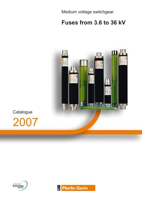
Medium voltage switchgear<br />
Fuses from 3.6 to 36 kV<br />
<strong>Catalog</strong>ue<br />
2007
0<br />
The Guiding System, the new way to create your<br />
electrical installations<br />
A comprehensive offer of products with consistent design<br />
The Guiding System is first and foremost a Merlin Gerin product<br />
offer covering all electrical distribution needs. However, what<br />
makes all the difference is that these products have been designed<br />
to operate togheter: mechanical and electrical compatibility,<br />
interoperability, modularity, communication.<br />
Thus the electrical installation is both optimised and more efficient:<br />
better continuity of supply, enhanced safety for people and<br />
equipment, guaranteed upgradeability, effective monitoring and<br />
control.<br />
Tools to simplify design and implementation<br />
With the Guiding System, you have a comprehensive range of tools<br />
- the Guiding Tools - that will help you increase your product<br />
knowledge and product utilisation. Of course this is in compliance<br />
with current standards and procedures.<br />
These tools include technical booklets and guides, design aid<br />
software, training courses, etc. and are regularly updated.<br />
For a genuine partnership with you<br />
Because each electrical installation is unique, there is no standard<br />
solution. With the Guiding System, the variety of combinations<br />
allows for genuine customisation solutions. You can create and<br />
implement electrical installations to meet your creative<br />
requirements and design knowledge.<br />
You and Merlin Gerin’s Guiding System form a genuine partnership.<br />
For more details on the Guiding System,<br />
consult www.merlin-gerin.com
0<br />
A consistent design of offers from<br />
Medium Voltage to Low Voltage<br />
All Merlin Gerin offers are designed according to<br />
electrical, mechanical and communication<br />
consistency rules.<br />
The products express this consistency by their<br />
overall design and shared ergonomics.<br />
<strong>Electric</strong>al consistency:<br />
Discrimination guarantees co-ordination between the operating<br />
characteristics of serial-connected circuit-breakers. Should a<br />
fault occurs downstream, only the circuit-breaker placed<br />
immediately upstream from the fault will trip.<br />
Each product complies with or enhances system performance at coordination<br />
level: breaking capacity, Isc, temperature rise, etc. for<br />
more safety, continuity of supply (discrimination) or economic<br />
optimisation (cascading).<br />
The leading edge technologies employed in Merlin Gerin’s<br />
Guiding System ensure high performance levels in discrimination<br />
and cascading of protection devices, electrodynamic withstand of<br />
switches and current distributors, heat loss of devices, distribution<br />
blocks and enclosures.<br />
Likewise, inter-product ElectroMagnetic Compatibilty (EMC) is<br />
guaranteed.<br />
Mechanical consistency:<br />
Each product adopts dimensional standards simplifying and<br />
optimising its use within the system.<br />
It shares the same accessories and auxiliaries and complies with<br />
global ergonomic choices (utilisation mode, operating mode, setting<br />
and configuration devices, tools, etc.) making its installation and<br />
operation within the system a simpler process.<br />
Direct connection of the Canalis KT busbar trunking on the<br />
Masterpact 3200 A circuit breaker.<br />
Communication consistency:<br />
Thanks to the use of standard Web technologies, you can offer<br />
your customers intelligent Merlin Gerin switchboards allowing<br />
easy access to information: follow-up of currents, voltages,<br />
powers, consumption history, etc.<br />
Each product complies with global choices in terms of<br />
communication protocols (Modbus, Ethernet, etc.) for simplified<br />
integration in the management, supervision and monitoring<br />
systems.<br />
Guiding Tools<br />
for more efficient design<br />
and implementation<br />
of your installations.
0<br />
SM6<br />
Medium voltage switchboard<br />
system from 1 to 36 kV<br />
Sepam<br />
Protection relays<br />
Masterpact<br />
Protection switchgear<br />
from 100 to 6300 A<br />
Trihal<br />
<strong>MV</strong>/LV dry cast resin<br />
transformer<br />
from 160 to 5000 kVA<br />
Evolis<br />
<strong>MV</strong> vacuum<br />
switchgear and<br />
components<br />
from 1 to 24 kV.<br />
The Technical guide<br />
These technical guides help you comply with<br />
installation standards and rules i.e.:<br />
The electrical installation guide, the<br />
protection guide, the switchboard<br />
implementation guide, the technical booklets<br />
and the co-ordination tables all form genuine<br />
reference tools for the design of highperformance<br />
electrical installations.<br />
For example, the LV protection co-ordination<br />
guide - discrimination and cascading -<br />
optimises choice of protection and<br />
connection devices while also increasing<br />
markedly continuity of supply in the<br />
installations.<br />
CAD software and tools<br />
The CAD software and tools enhance<br />
productivity and safety.<br />
They help you create your installations<br />
by simplifying product choice through<br />
easy browsing in the Guiding System<br />
offers.<br />
Last but not least, they optimise<br />
use of our products while also complying<br />
with standards and proper procedures.
0<br />
Compact<br />
Protection switchgear system<br />
from 100 to 630 A<br />
Multi 9<br />
Modular protection switchgear<br />
system up to 125 A<br />
Prisma Plus<br />
Functional system for electrical<br />
distribution switchboards<br />
up to 3200 A<br />
Pragma<br />
Enclosures for<br />
distribution<br />
switchboards<br />
up to 160 A<br />
Canalis<br />
Prefabricated Busbar<br />
Trunking<br />
from 25 to 4000 A<br />
PowerLogic<br />
Power<br />
management<br />
Training<br />
Training allows you to acquire the Merlin<br />
Gerin expertise (installation design, work<br />
with power on, etc.) for increased<br />
efficiency and a guarantee of improved<br />
customer service.<br />
The training catalogue includes beginner’s<br />
courses in electrical distribution,<br />
knowledge of <strong>MV</strong> and LV switchgear,<br />
operation and maintenance of<br />
installations, design of LV installations to<br />
give but a few examples.<br />
merlin-gerin.com<br />
This international site allows you to access<br />
all the Merlin Gerin products in just 2 clicks<br />
via comprehensive range data-sheets, with<br />
direct links to:<br />
b complete library: technical documents,<br />
catalogs, FAQs, brochures…<br />
b selection guides from the e-catalog<br />
b product discovery sites and their Flash<br />
animations.<br />
You will also find illustrated overviews,<br />
news to which you can subscribe, the list<br />
of country contacts…
This international site<br />
allows you to access all<br />
the Merlin Gerin products<br />
in just 2 clicks via<br />
comprehensive range<br />
data-sheets, with direct<br />
links to:<br />
b complete library:<br />
technical documents,<br />
catalogs, FAQs,<br />
brochures…<br />
b selection guides from<br />
the e-catalog.<br />
b product discovery sites<br />
and their Flash<br />
animations.<br />
You will also find<br />
illustrated overviews,<br />
news to which you can<br />
subscribe, the list of<br />
country contacts…<br />
These technical guides<br />
help you comply with<br />
installation standards<br />
and rules i.e.:<br />
the electrical installation<br />
guide, the protection<br />
guide, the switchboard<br />
implementation guide,<br />
the technical booklets<br />
and the co-ordination<br />
tables all form genuine<br />
reference tools for<br />
the design of high<br />
performance electrical<br />
installations.<br />
For example, the LV<br />
protection co-ordination<br />
guide - discrimination and<br />
cascading - optimises<br />
choice of protection and<br />
connection devices while<br />
also increasing markedly<br />
continuity of supply in the<br />
installations.
Medium voltage <strong>fuses</strong><br />
from 3.6 kV to 36 kV<br />
Contents<br />
Applications<br />
Fuse range selection 2<br />
Main characteristics 3<br />
Fusarc CF, Soléfuse, Tépéfuse, MGK<br />
Construction 5<br />
<strong>MV</strong> limiting <strong>fuses</strong> with thermal striker<br />
Construction 6<br />
Fusarc CF<br />
Characteristics and dimensions 7<br />
References and characteristics 8<br />
Fuse and limitation curves 9<br />
Soléfuse<br />
References and characteristics 10<br />
Fuse and limitation curves 11<br />
Tépéfuse, Fusarc CF<br />
Metering transformer protection 12<br />
MGK<br />
References, characteristics and curves 13<br />
Selection and usage guide<br />
General - Transformer protection 14<br />
Transformer protection - Selection table 15<br />
Motor protection 16<br />
Motor protection - Selection charts 17<br />
Capacitor bank protection<br />
Comments on substituting <strong>fuses</strong> 18<br />
Order form 19<br />
1
Presentation<br />
Applications<br />
Fuse range selection<br />
058579N<br />
Our Fusarc CF, Soléfuse, Tépéfuse and MGK <strong>fuses</strong> make up a broad, consistent<br />
and uniform range of high breaking capacity <strong>fuses</strong> and current limitors.<br />
They are all of combined type and are manufactured so that they can be installed<br />
both indoors and outdoors (depending on the type).<br />
058580N<br />
Public distribution<br />
Merlin Gerin <strong>fuses</strong> provide protection to medium voltage distribution devices<br />
(from 3 to 36 kV) from both the dynamic and thermal effects of short-circuit currents<br />
greater than the fuse’s minimum breaking current.<br />
Considering their low cost and their lack of required maintenance, medium voltage<br />
<strong>fuses</strong> are an excellent solution to protect various types of distribution devices:<br />
b Medium voltage current consumers (transformers, motors, capacitors, etc.)<br />
b Public and industrial electrical distribution networks.<br />
They offer dependable protection against major faults that can occur either<br />
on medium or low voltage circuits.<br />
This protection can be further enhanced by combining the <strong>fuses</strong> with low voltage<br />
protection systems or with an overcurrent relay.<br />
Selection table<br />
Depending on the equipment to be protected and its voltage rating, the table below<br />
gives the range of <strong>fuses</strong> which are best suited to the protection application.<br />
Motor protection<br />
Voltage<br />
(kV)<br />
Motors Power<br />
transformers<br />
Capacitors Voltage<br />
transformers<br />
3.6 Fusarc CF Fusarc CF Fusarc CF Fusarc CF<br />
MGK<br />
7.2 Fusarc CF Fusarc CF Fusarc CF Fusarc CF<br />
MGK Soléfuse Soléfuse<br />
12 Fusarc CF Fusarc CF Fusarc CF Tépéfuse<br />
Soléfuse Soléfuse Fusarc CF<br />
17.5 Fusarc CF Fusarc CF Tépéfuse<br />
Soléfuse Soléfuse Fusarc CF<br />
24 Fusarc CF Fusarc CF Tépéfuse<br />
Soléfuse Fusarc CF<br />
Soléfuse<br />
36 Fusarc CF Fusarc CF Tépéfuse<br />
Soléfuse Soléfuse Fusarc CF<br />
Soléfuse<br />
(UTE standard;<br />
transformer protection)<br />
MGK<br />
(UTE standard;<br />
motor protection)<br />
058578N<br />
Fusarc CF<br />
(DIN standard;<br />
transformer, motor and<br />
capacitor protection)<br />
Tépéfuse<br />
(UTE standard;<br />
voltage transformer protection)<br />
2
Presentation<br />
Main characteristics<br />
PE55711<br />
Key characteristics<br />
The most signifi cant features provided by our range of <strong>fuses</strong> are as follows:<br />
b High breaking capacity<br />
b High current limitation<br />
b Low I 2 t values<br />
b Dependable breaking of critical currents<br />
b Low breaking overvoltage<br />
b Low dissipated power<br />
b No maintenance or ageing<br />
b For indoor and outdoor applications<br />
b With a thermal striker<br />
b Low minimum breaking current values.<br />
Standards<br />
Our <strong>fuses</strong> are designed and manufactured according to the following standards:<br />
b IEC 60282-1, IEC 60787 (Fusarc CF, Soléfuse,Tépéfuse, MGK)<br />
b DIN 43625 (Fusarc CF)<br />
b VDE 0670-402 (Fusarc CF)<br />
b UTE C64200, C64210 (Soléfuse, Tépéfuse).<br />
Quality assurance system<br />
In addition to being tested in our own laboratories as well as in offi cial laboratories<br />
such as the CESI, Les Renardiers and Labein, with their own respective certificates,<br />
our <strong>fuses</strong> are manufactured according to quality guidelines within the framework<br />
of the ISO 9001 and ISO 14001 Quality System Certifi cation awarded by AENOR<br />
(IQ-NET) which provides an additional guarantee for Merlin Gerin products.<br />
Routine testing<br />
During manufacture, each fuse is subject to systematic routine testing, with the aim<br />
of checking its quality and conformity:<br />
b Dimensional control and weight control<br />
b Visual control of markings, labelling and external appearance<br />
b <strong>Electric</strong>al resistance measurement: a key point to ensure that <strong>fuses</strong> have<br />
the required performance levels at the end of the production process and to check<br />
that no damage has occurred during assembly.<br />
Measurement of the room temperature resistance of each fuse is therefore carried<br />
out in order to check that they are in line with values, according to their rated voltage<br />
and rated current.<br />
Certified quality: ISO 9001 and ISO 14001<br />
A major advantage<br />
<strong>Schneider</strong> <strong>Electric</strong> has a functional organisation whose main mission is to check<br />
quality and monitor compliance with standards in each of its production units.<br />
MESA, the only company in <strong>Schneider</strong> <strong>Electric</strong> that makes <strong>fuses</strong>, is certifi ed<br />
by AENOR (The Spanish Standards Association), and is certifi ed to ISO 9001<br />
and ISO 14001 (IQ-NET).<br />
Furthermore, Merlin Gerin annually carries out internal type-testing and breaking<br />
testing in order to comply with our annual quality assurance plan, which is available<br />
on request to our customers.<br />
b Seal testing: in order to test the sealing of our Fusarc CF <strong>fuses</strong>, they are immersed<br />
for 5 minutes in a hot water bath (80°C), in accordance with standard IEC 60282-1.<br />
3
Presentation<br />
Main characteristics<br />
DE55750<br />
Key definitions<br />
Un: rated voltage<br />
This is the highest voltage between phases (expressed in kV) for the network<br />
on which the fuse might be installed.<br />
In the medium voltage range, the preferred rated voltages have been set at:<br />
3.6 - 7.2 - 12 - 17.5 - 24 and 36 kV.<br />
Safe operating<br />
range<br />
In: rated current<br />
This is the current value that the fuse can withstand on a constant basis without<br />
any abnormal temperature rise (generally 65 Kelvin for the contacts).<br />
I3: minimum rated breaking current<br />
This is the minimum current value which causes the fuse to blow and break<br />
the current. For our <strong>fuses</strong>, these values are between 3 and 5 times the In value.<br />
Comment: it is not enough for a fuse to blow in order to interrupt the fl ow of current.<br />
For current values less than I3 , the fuse will blow, but may not break the current.<br />
Arcing continues until an external event interrupts the current. It is therefore<br />
essential to avoid using a fuse in the range between In and I3.<br />
Overcurrents in this range may irreversibly damage fuse elements, whilst still<br />
maintaining the risk of an arc which is not broken, and of them being destroyed.<br />
Figure 1 shows the operating ranges of combined type <strong>fuses</strong>.<br />
I2: critical currents (currents giving similar conditions to the maximum arcing<br />
energy). This current subjects the fuse to greater thermal and mechanical stresses.<br />
The value of I2 varies between 20 and 100 times the In value, depending on<br />
the design of the fuse element. If the fuse can break this current, it can also break<br />
currents between I3 and I1.<br />
Figure 1: definition of a fuse’s operating zone.<br />
I1: maximum rated breaking current<br />
This is the presumed fault current that the fuse can interrupt. This value is very high<br />
for our <strong>fuses</strong> ranging from 20 to 63 kA.<br />
Comment: it is necessary to ensure that the network short circuit current is at least<br />
equal to the I1 current of the fuse that is used.<br />
4
Fuses<br />
Fusarc CF, Soléfuse, Tépéfuse, MGK<br />
Construction<br />
DE55751EN<br />
Force (N)<br />
80<br />
70<br />
60<br />
50<br />
40<br />
30<br />
20<br />
10<br />
0<br />
0 5 10 15 20 23 Travel<br />
(mm)<br />
Figure 2: this graph shows the value<br />
of the force provided by the striker<br />
according to its length of travel.<br />
End contact caps (1)<br />
Together with the enclosure, they form an assembly which must remain intact<br />
before, during and after breaking the current. This is why they have to withstand<br />
mechanical stresses and sealing stresses due to overpressure caused by arcing.<br />
The stability of the internal components must also be ensured over time.<br />
Enclosure (2)<br />
This part of the fuse must withstand certain specifi c stresses (related to what<br />
has already been mentioned):<br />
b Thermal stresses: the enclosure has to withstand the rapid temperature rise<br />
that occurs when the arc is extinguished<br />
b <strong>Electric</strong>al stresses: the enclosure has to withstand the restoring of current after<br />
breaking<br />
b Mechanical stresses: the enclosure has to withstand the increase in pressure<br />
caused by the expansion of the sand when breaking occurs.<br />
Core (3)<br />
This is a cylinder surrounded by ceramic fins onto which the fuse element is wound.<br />
The striker control wire together with the latter are fi tted in the cyclinder. They are<br />
insulated from the fuse elements.<br />
Fuse element (4)<br />
This is the main component of the fuse. It is made from materials with very low<br />
resistance and which do not wear over time. Our fuse elements are carefully<br />
confi gured following a lot of testing, to enable us to achieve the required results.<br />
Extinction powder (5)<br />
The extinction powder is made up of high purity quartzite sand (over 99.7%),<br />
which is free from any metal compounds and moisture.<br />
When it vitrifi es, the sand absorbs the energy produced by the arc and forms<br />
an insulating compound called fulgurite with the fuse element.<br />
PE55712<br />
1 Contact caps<br />
2 Enclosure<br />
3 Core<br />
4 Fuse element<br />
5 Extinction powder<br />
6 Thermal striker<br />
Thermal striker (6)<br />
This is a mechanical device which indicates correct fuse operation.<br />
It also provides the energy required to actuate a combined breaking device.<br />
The striker is controlled by a heavy duty wire which, once the fuse element<br />
has blown, also melts and releases the striker. It is very important that the control<br />
wire does not cause premature tripping of the striker, nor must it interfere with<br />
the breaking process.<br />
The Merlin Gerin limiting fuse, with its thermal striker, is not only capable of indicating<br />
and breaking short circuits. It is also capable of this for prolonged overcurrents,<br />
and currents causing signifi cant temperature rises in the devices combined with<br />
the <strong>fuses</strong> and the <strong>fuses</strong> themselves.<br />
The thermal strikers installed in our <strong>fuses</strong> are of “medium type” and their force/travel<br />
characteristics (approximately 1 joule according to standard IEC-60282-1) are shown<br />
in fi gure 2.<br />
PE55713<br />
Figure 3: cross sectional diagram of a fuse<br />
5
Fuses<br />
<strong>MV</strong> limiting <strong>fuses</strong><br />
with thermal striker<br />
Construction<br />
PE55717<br />
All Merlin Gerin <strong>fuses</strong> (type Fusarc CF) are provided of a thermal protection device.<br />
In the case of permanent overcurrents lower than I3 and superior to the rated<br />
current (In), the fuse mechanical striker acts opening the device associated and<br />
avoiding any incidents due to overheatings.<br />
In this way, the fuse not only works as a current limiter but also as a temperature<br />
limiter when combined with an external breaking device.<br />
These types of <strong>fuses</strong>, which integrate a thermal striker, are fully compatible with<br />
standard Back UP type <strong>fuses</strong>.<br />
Figure 1.1 shows thermal protection action zone.<br />
Fusarc CF <strong>fuses</strong> installed in a CAS 36 cubicle<br />
Technical / economic / safety advantages:<br />
The use of a thermal protector in our <strong>fuses</strong> provides the following advantages:<br />
b Protecting the <strong>fuses</strong> and their environment from unacceptable temperature rises<br />
in installations equipped with a disconnecting switch with the possibility of automatic<br />
opening<br />
b Providing a response to unexpected operating conditions, to frequent or longlasting<br />
overloads, or to mistakes in selecting the fuse rating, or even concerning restricted<br />
ventilation conditions within the installation<br />
b Indicating and protecting against overloads caused by overcurrents below the<br />
minimum breaking current (I3) of the installed fuse and which can cause dangerous<br />
operating temperatures<br />
b Reducing operating costs due to destruction of equipment or excess costs caused<br />
by loss of quality of service (repair time, staff, etc.).<br />
This thermal protector safety feature, signifi cantly reduces the risk of damage<br />
and accidents in installations and therefore increases the power distribution quality<br />
of service.<br />
The characteristics of the thermal striker fuse (breaking capacity, fuse curves,<br />
limiting values, striker force, etc.) do not vary relative to our <strong>fuses</strong> without<br />
thermal protection.<br />
DE55754<br />
Thermal striker<br />
action zone<br />
Figure 1.1: thermal protection<br />
6
Fuses<br />
Fusarc CF<br />
Characteristics and dimensions<br />
DE55753<br />
Dimensions (mm)<br />
Figure 4<br />
Ø45<br />
33<br />
L*<br />
Striker<br />
* The following page gives the diameter and length<br />
of the fuse according to its rating.<br />
* For other dimensions, please contact our sales department.<br />
Ø*<br />
33<br />
Ø6<br />
23<br />
Fusarc CF<br />
This is <strong>Schneider</strong> <strong>Electric</strong>’s DIN standard fuse range.<br />
When designing this range, we paid particular attention to minimise power dissipation.<br />
It is increasingly common to use RMU units with SF6 gas as the insulating material.<br />
In view of these operating conditions, in which the fuse is inserted inside a<br />
hermetically sealed fuse chamber, with virtually no ventilation, these <strong>fuses</strong> avoid<br />
premature ageing of themselves and of the whole device which would otherwise<br />
be caused by a non-optimised fuse.<br />
The enclosure in the Fusarc CF range up to 100 A (rated current) is made from<br />
crystallised brown porcelain which withstands ultra-violet radiation and can therefore<br />
be installed both outdoors and indoors.<br />
Fuses with rated current values greater than 100 A have glass fi bre enclosures<br />
and are only for indoor installations.<br />
You will find the full list of the Fusarc CF range in the table given on the following page.<br />
With rated voltages ranging from 3 to 36 kV and rated currents of up to 250 A,<br />
they meet customers’ exact requirements in terms of switchgear short-circuit<br />
protection.<br />
Time/current fuse curves<br />
These curves show the virtual fusion or pre-arcing time, as a function of the value<br />
of the symmetrical component of the intended current. Careful selection and design<br />
of fuse elements, together with meticulous industrial control, provides Merlin Gerin<br />
customers with precise time-current curves, well above the tolerance limits provided<br />
for in standard IEC 60282-1.<br />
When designing our Fusarc CF <strong>fuses</strong>, we focused on a relatively high fusion current<br />
at 0.1 s in order to withstand transformer making currents and at the same time<br />
a low fusion current at 10 s in order to achieve quick breaking in the case of a fault.<br />
On page 10, we give the time/current characteristics of Fusarc CF <strong>fuses</strong>.<br />
Current limitation curves<br />
Merlin Gerin <strong>fuses</strong> are current limiting. Consequently, short circuit currents are<br />
limited without reaching their maximum value. These diagrams show the relationship<br />
between the presumed short-circuit current and the peak value of the current broken<br />
by the fuse. The intersection of these lines with straight lines for Imax symmetrical<br />
and Imax asymmetrical give the presumed breaking current, below which <strong>fuses</strong><br />
no longer have their limiting capacity.<br />
For example, as shown in the limitation curves on page 10, for a short-circuit<br />
whose presumed current is 5 kA, in an unprotected installation, the maximum current<br />
value would be 7 kA for symmetrical fl ow and 13 kA for an asymmetrical case.<br />
If we had used a Fusarc CF fuse with a rated current of 16 A, the maximum value<br />
reached would have been 1.5 kA.<br />
7
Fuses<br />
Fusarc CF<br />
References and characteristics<br />
Table no. 1<br />
Reference<br />
Rated<br />
voltage (kV)<br />
Operating<br />
voltage (kV)<br />
Rated<br />
current (A)<br />
Max. breaking<br />
current I1 (kA)<br />
Min. breaking<br />
current I3 (A)<br />
Cold resistance*<br />
(mΩ)<br />
Dissipated<br />
power (W)<br />
Length<br />
(mm)<br />
Diameter<br />
(mm)<br />
757372 AR 3.6 3/3.6 250 50 2.000 0.6 58 292 86 3.4<br />
51311 006 M0 4 20 762 20<br />
51006 500 M0 6.3 36 205 12<br />
51006 501 M0 10 34 102 14<br />
51006 502 M0 16 50 68.5 26<br />
50.5 1<br />
51006 503 M0 20 62 53.5 32<br />
51006 504 M0 25 91 36.4 35<br />
51006 505 M0 31.5 63 101 26 42 192<br />
51006 506 M0 7.2 3/7.2 40 135 18 46<br />
55 1.3<br />
51006 507 M0 50 180 11.7 44<br />
51006 508 M0 63 215 8.4 52<br />
51006 509 M0 80 280 6.4 68<br />
76 2.1<br />
51006 510 M0 100 380 5.5 85<br />
757352 BN 125 650 3.4 88<br />
757352 BP 160 50 1.000 2.2 87 292<br />
3.4<br />
86<br />
757352 BQ 200 1.400 1.8 95<br />
757374 BR 250 2.200 0.9 95 442 5<br />
51311 007 M0 4 20 1143 27<br />
51006 511 M0 6.3 36 319 16<br />
51006 512 M0 10 34 158 18<br />
51006 513 M0 16 50 106 37<br />
50.5 1.2<br />
51006 514 M0 20 62 82 42<br />
51006 515 M0 25 91 56 52<br />
51006 516 M0 31.5 63 101 40 59 292<br />
51006 517 M0 12 6/12 40 135 28 74<br />
55 1.8<br />
51006 518 M0 50 180 17.4 70<br />
51006 519 M0 63 215 13.8 82<br />
51006 520 M0 80 280 10 102<br />
76 3.2<br />
51006 521 M0 100 380 8 120<br />
757364 CN 125 650 5.3 143<br />
757354 CP 160 40 1.000 3.5 127 442 86 5<br />
757354 CQ 200 1.400 2.7 172<br />
51006 522 M0 10 34 203 23<br />
51006 523 M0 16 50 132 47 50.5 1.2<br />
51006 524 M0 25 91 71 72 292<br />
51006 525 M0 31.5 101 51 78<br />
51006 526 M0 40 135 35 90<br />
76 3.2<br />
51311 008 M0 4 20 1436 34<br />
51006 527 M0 6.3 40 36 402 21<br />
51006 528 M0 10 34 203 25<br />
51006 529 M0 17.5 10/17.5 16 50 132 46<br />
50.5 1.5<br />
51006 530 M0 20 62 103 52<br />
51006 531 M0 25 91 71 66<br />
51006 532 M0 31.5 101 51 74 367<br />
51006 533 M0 40 135 35 94<br />
55 2.2<br />
51006 534 M0 50 180 22 93<br />
51006 535 M0 63<br />
215 19.4 121 76 3.9<br />
31.5<br />
51006 536 M0 80 330 13.5 145<br />
51006 537 M0 100 450 11 192 86 4.6<br />
Weight<br />
(kg)<br />
* Resistances are given at ±10% for a temperature of 20°C. Fuses > 100 A rated current,<br />
are manufactured in glass fibre (for indoor use).<br />
8
Fuses<br />
Fusarc CF<br />
References and characteristics<br />
Table no. 1 (continued)<br />
Reference<br />
Rated<br />
voltage (kV)<br />
Operating<br />
voltage (kV)<br />
Rated<br />
current (A)<br />
Max. breaking<br />
current I1 (kA)<br />
Min. breaking<br />
current I3 (A)<br />
Cold resistance*<br />
(mΩ)<br />
Dissipated<br />
power (W)<br />
Length<br />
(mm)<br />
Diameter<br />
(mm)<br />
51108 807 M0 10 36 485 26 50.5 1.5<br />
51108 808 M0 16 50 158 58<br />
51108 813 M0 20 62 123 67 367<br />
55 2.2<br />
51108 814 M0 25 91 85 76<br />
51108 809 M0 31.5 101 61 93 76 3.9<br />
51108 810 M0 40 135 42 115<br />
51311 009 M0 4 40 20 1436 34<br />
51006 538 M0 6.3 36 485 25<br />
51006 539 M0 10 34 248 31<br />
50.5 1.7<br />
51006 540 M0 16 50 158 58<br />
442<br />
51006 541 M0 20 62 123 67<br />
51006 542 M0 25 91 85 79<br />
51006 543 M0 24 10/24 31.5 101 61 96<br />
51006 544 M0 40 135 42 119<br />
55 2.6<br />
51108 915 M0 6.3 38 484 26<br />
51108 916 M0 10 40 248 35<br />
51108 917 M0 16 60 158 64<br />
50.5 1.2<br />
51108 918 M0 20 73 123 84<br />
51108 919 M0 25 100 88 79 292<br />
51108 920 M0 31.5 112 61 90<br />
76 3.2<br />
51108 921 M0 40 31.5 164 45 120<br />
51108 922 M0 50 233 30 157 86 5<br />
51108 923 M0 63 247 23 177<br />
51006 545 M0 50 180 31.5 136<br />
51006 546 M0 63 215 22.8 144<br />
76 4.5<br />
442<br />
51006 547 M0 80 330 18 200<br />
51006 548 M0 100 450 13.5 240 86 5.7<br />
51311 010 M0 4 20 2109 51<br />
51006 549 M0 6.3 36 750 39<br />
51006 550 M0 10 34 380 50 50.5 1.9<br />
51006 551 M0 16 50 252 98<br />
51006 552 M0 20 62 197 120<br />
51006 553 M0 36 20/36 25 20 91 133 133 537 55 3.1<br />
51006 554 M0 31.5 101 103 171<br />
51006 555 M0 40 135 70 207<br />
76 5.4<br />
51006 556 M0 50 200 47 198<br />
51006 557 M0 63 250 35 240<br />
86 6.5<br />
Weight<br />
(kg)<br />
* Resistances are given at ±10% for a temperature of 20 °C. Fuses > 100 A rated current,<br />
are manufactured in glass fibre (for indoor use).<br />
9
Fuses<br />
Fusarc CF<br />
Fuse and limitation curves<br />
Time/current characteristics curves<br />
3.6 - 7.2 - 12 - 17.5 - 24 - 36 kV<br />
Time (s)<br />
DE55755<br />
1000<br />
86<br />
4<br />
4 A<br />
6.3 A<br />
10 A<br />
16 A<br />
20 A<br />
25 A<br />
31.5 A<br />
40 A<br />
50 A<br />
63 A<br />
80 A<br />
100 A<br />
125 A<br />
160 A<br />
200 A<br />
250 A<br />
2<br />
100<br />
8<br />
6<br />
4<br />
2<br />
10<br />
8<br />
6<br />
4<br />
2<br />
1<br />
8<br />
6<br />
4<br />
2<br />
0.1<br />
8<br />
6<br />
4<br />
2<br />
0.01<br />
10<br />
2 4 6 8 2 4 6 8 2 4 6 8<br />
100<br />
1000<br />
10000<br />
Current (A)<br />
The diagram shows the maximum limited broken current<br />
value as a function of the rms current value which could<br />
have occurred in the absence of a fuse.<br />
DE55756<br />
Current limitation curves 3.6 - 7.2 - 12 - 17.5 - 24 - 36 kV<br />
Maximum value of cut-off current (kA peak)<br />
100<br />
8<br />
6<br />
4<br />
2<br />
10<br />
8<br />
6<br />
4<br />
2<br />
Ia = 1.8 Ik 2<br />
Is = Ik 2<br />
250 A<br />
200 A<br />
160 A<br />
125 A<br />
100 A<br />
80 A<br />
63 A<br />
50 A<br />
40 A<br />
31.5 A<br />
25 A<br />
20 A<br />
16 A<br />
10 A<br />
6.3 A<br />
1<br />
8<br />
6<br />
4 A<br />
4<br />
2<br />
0.1<br />
6 8 2 4 6 8 2 4 6 8 2 4 6 8<br />
0.1<br />
1<br />
10<br />
100<br />
Rms value of the presumed broken current (kA)<br />
10
Fuses<br />
Soléfuse<br />
References and characteristics<br />
Table no. 2<br />
Reference<br />
Rated voltage<br />
(kV)<br />
Operating voltage<br />
(kV)<br />
The Soléfuse range of <strong>fuses</strong> is manufactured according to UTE standard C64200.<br />
The rated voltage varies from 7.2 to 36 kV. They can be supplied with or without<br />
a striker and their weight is of around 2 kg.<br />
They are mainly intended to protect power transformers and distribution networks,<br />
and are solely for indoor installations (glass fi bre enclosure).<br />
<strong>Electric</strong>al characteristics<br />
Rated current<br />
(A)<br />
Min. breaking current<br />
I3 (A)<br />
Max. breaking current<br />
I1 (kA)<br />
Cold resistance *<br />
(mΩ)<br />
757328 BC 6.3 31.5 158.6<br />
757328 BE 16 80 51.7<br />
757328 BH 7.2 3/7.2 31.5 157.5 50 24.5<br />
757328 BK 63 315 11.3<br />
757328 BN 125 625 4.8<br />
757328 CM 7.2/12 3/12 100 500 50 7.7<br />
757328 DL 7.2/17.5 3/17.5 80 400 40 15.1<br />
757328 EC 6.3 31.5 445.9<br />
757328 EE 16 80 93.2<br />
757328 EH 12/24 10/24 31.5 157.5 30 45.8<br />
757328 EJ 43 215 38.5<br />
757328 EK 63 315 18.9<br />
757331EC** 6.3 31.5 447.3<br />
757331EE** 16 80 147.4<br />
757331EH** 12/24 10/24 31.5 157.5 30 67.9<br />
757331EJ** 43 215 39<br />
757331EK** 63 315 19.3<br />
757328 FC 6.3 31.5 618.9<br />
757328 FD 10 50 252.9<br />
757328 FE 36 30/36 16 80 20 207.8<br />
757328 FF 20 100 133.2<br />
757328 FG 25 125 124<br />
757328 FH 31.5 157.5 93<br />
* Resistances are given at ±10% for a temperature of 20°C.<br />
** Fuses with a reference number starting by 757328 have a striker,<br />
those that start by 757331 do not.<br />
DE55752<br />
Dimensions (mm)<br />
Figure 5<br />
520<br />
Striker<br />
Ø6<br />
Ø55<br />
35<br />
450<br />
Weight: 2.3 kg<br />
23 max.<br />
11
Fuses<br />
Soléfuse<br />
Fuse and limitation curves<br />
Time/current characteristic curves<br />
7.2 - 12 - 17.5 - 24 - 36 kV<br />
Time (s)<br />
DE55757<br />
1000<br />
8<br />
6<br />
4<br />
6.3 A<br />
10 A<br />
16 A<br />
20 25 A<br />
31.5 A<br />
43 A<br />
63 A<br />
80 A<br />
100 A<br />
125 A<br />
2<br />
100<br />
86<br />
4<br />
2<br />
10 86<br />
4<br />
2<br />
1<br />
8<br />
6<br />
4<br />
2<br />
0.1 86<br />
4<br />
2<br />
0.01<br />
10<br />
2 4 6 8<br />
100<br />
2 4 6 8<br />
1000<br />
2 4 6 8<br />
10000<br />
Current (A)<br />
The diagram shows the maximum limited broken current<br />
value as a function of the rms current value which could<br />
have occurred in the absence of a fuse.<br />
DE55758<br />
Current limitation curves 7.2 - 12 - 17.5 - 24 - 36 kV<br />
Maximum value of cut-off current (kA peak)<br />
100<br />
8<br />
6<br />
4<br />
2<br />
10<br />
8<br />
6<br />
4<br />
2<br />
Ia = 1.8 Ik 2<br />
Is = Ik 2<br />
125 A<br />
100 A<br />
80 A<br />
63 A<br />
43 A<br />
31.5 A<br />
25 A<br />
20 A<br />
16 A<br />
10 A<br />
6.3 A<br />
1<br />
8<br />
6<br />
4<br />
2<br />
0.1<br />
0.1<br />
2 4 6 8 2 4 6 8 2 4 6 8<br />
1 10 100<br />
Rms value of the presumed broken current (kA)<br />
12
Fuses<br />
Tépéfuse, Fusarc CF<br />
(metering transformer protection)<br />
References, characteristics and curves<br />
We manufacture Tépéfuse and Fusarc CF type <strong>fuses</strong> intended for metering<br />
transformer protection which have the following references and characteristics:<br />
Characteristics<br />
Table no. 3<br />
Type Reference Rated Operating Rated Max. breaking Min. breaking Cold Length Diameter Weight<br />
voltage<br />
(kV)<br />
voltage<br />
(kV)<br />
current<br />
(A)<br />
current<br />
I1 (kA)<br />
current<br />
I3 (A)<br />
resistance *<br />
(mΩ) (mm) (mm) (kg)<br />
Tépéfuse 781825 A 12 < 12<br />
6.1<br />
0.3 40 40<br />
781825 B 24 13.8/24 11.6<br />
301 27.5 0.4<br />
Fusarc CF 51311 002 MO 7.2 3/7.2 2.5 1278 192 0.9<br />
51311 000 MO<br />
1 63 3834<br />
12 6/12<br />
51311 003 MO 2.5 1917<br />
292 1.2<br />
51311 011 MO 17.5 10/17.5 2.5 9.5 2407 367 50.5 1.5<br />
51311 001 MO<br />
1 40 4815<br />
24 10/24<br />
51311 004 MO 2.5 2407<br />
442 1.6<br />
51311 005 MO 36 20/36 2.5 20 3537 537 1.8<br />
* Resistances are given at ±10% for a temperature of 20°C.<br />
Tépéfuse <strong>fuses</strong> are only made in glass fibre when intended for indoor usage.<br />
Fuses for transformer protection are made without strikers, according to figures 6 and 7.<br />
Dimensions (mm)<br />
Fusarc CF (Figure 6)<br />
Fuse curve 7.2 - 12 - 24 - 36 kV<br />
Time (s)<br />
DE55759<br />
Ø 45 Ø 50.5<br />
33 L<br />
DE55765<br />
1 A (Fusarc CF)<br />
0.3 A (Tépéfuse)<br />
2.5 A (Fusarc CF)<br />
1000 86<br />
4<br />
DE55760<br />
Tépéfuse (Figure 7)<br />
331<br />
2<br />
Ø27.5<br />
100 86<br />
4<br />
15<br />
301<br />
2<br />
10 86<br />
4<br />
2<br />
1<br />
8<br />
6<br />
4<br />
2<br />
0.1 86<br />
4<br />
2<br />
0.01<br />
1<br />
2 4 6 8 2 4 6 8<br />
10 100<br />
Current (A)<br />
13
Fuses<br />
MGK<br />
References, characteristics and curves<br />
DE55761<br />
Dimensions (mm)<br />
Figure 8<br />
Ø 81<br />
Weight: 4.1 kg<br />
438<br />
Striker<br />
55<br />
MGK <strong>fuses</strong> are intended to protect medium voltage motors at 7.2 kV<br />
(indoor application).<br />
<strong>Electric</strong>al characteristics<br />
Table no. 4<br />
Reference<br />
Rated<br />
voltage<br />
(kV)<br />
Operating<br />
voltage<br />
(kV)<br />
Rated<br />
current<br />
(A)<br />
Min. breaking<br />
current<br />
I3 (A)<br />
Max. breaking<br />
current<br />
I1 (kA)<br />
Cold<br />
resistance *<br />
(mΩ)<br />
757314 100 360 50 6.4<br />
757315 125 570 50 4.6<br />
757316 7.2 y 7.2 160 900 50 2.4<br />
757317 200 1400 50 1.53<br />
757318 250 2200 50 0.95<br />
* Resistances are given at ±10% for a temperature of 20°C.<br />
Fuse curve 7.2 kV<br />
Time (s)<br />
DE55762<br />
1000<br />
8<br />
6<br />
4<br />
100 A<br />
125 A<br />
160 A<br />
200 A<br />
250 A<br />
2<br />
100<br />
86<br />
4<br />
2<br />
10 86<br />
4<br />
2<br />
1<br />
8<br />
6<br />
4<br />
2<br />
0.1 86<br />
4<br />
2<br />
The diagram shows the maximum limited broken current<br />
value as a function of the rms current value which could<br />
have occurred in the absence of a fuse.<br />
DE55763<br />
0.01<br />
10<br />
2 4 6 8<br />
100<br />
2 4 6 8<br />
1000<br />
2 4 6 8<br />
10000<br />
Current limitation curve 7.2 kV<br />
Maximum value of limited broken current (kA peak)<br />
100<br />
8<br />
6<br />
4<br />
2<br />
10<br />
8<br />
6<br />
Ia = 1.8 Ik 2<br />
Is = Ik 2<br />
Current (A)<br />
250 A<br />
200 A<br />
160 A<br />
125 A<br />
100 A<br />
4<br />
2<br />
1<br />
8<br />
6<br />
4<br />
2<br />
0.1<br />
0.1<br />
2 4 6 8<br />
2 4 6 8 2 4 6 8<br />
1 10 100<br />
Rms value of presumed broken current (kA)<br />
14
Fuses<br />
Selection and usage guide<br />
General<br />
Transformer protection<br />
DE55764<br />
I cc<br />
Short circuit<br />
current<br />
General<br />
According to their specifi c characteristics, the various types of <strong>fuses</strong> (Fusarc CF,<br />
Soléfuse, Tépéfuse and MGK) provide real protection for a wide variety of medium<br />
and high voltage equipment (transformers, motors, capacitors).<br />
It is of the utmost importance to always remember the following points:<br />
b Un of the fuse must be greater than or equal to the network voltage<br />
b I1 of a fuse must be greater than or equal to the network short circuit current<br />
b The characteristics of the equipment to be protected must always be taken into<br />
consideration.<br />
I 3<br />
I n<br />
(1)<br />
I n<br />
I<br />
Closing<br />
Transformer protection<br />
A transformer imposes three main stresses on a fuse. This is why the <strong>fuses</strong> must be<br />
capable of:<br />
b … Withstanding the peak start-up current which accompanies transformer<br />
closing<br />
The <strong>fuses</strong>’ fusion current at 0.1 s must be more than 12 times the transformer’s rated<br />
current.<br />
If(0.1 s) > 12 x In transfo.<br />
Fuse<br />
Transformer<br />
(1) In this current zone, any overloads must be eliminated<br />
by LV protection devices or by a <strong>MV</strong> switch equipped with<br />
an overcurrent relay.<br />
b … Breaking fault currents across the terminals of the transformer secondary<br />
A fuse intended to protect a transformer has to break its rated short circuit current<br />
(Isc) before it can damage the transformer.<br />
Isc > If(2 s)<br />
b … Withstanding the continuous operating current together with possible<br />
overloads<br />
In order to achieve this, the fuse’s rated current must be over 1.4 times<br />
the transformer’s rated current.<br />
In fuse > 1.4 In transfo.<br />
Choice of rating<br />
In order to correctly select the fuse’s rated current to protect a transformer,<br />
we have to know and take account of:<br />
b The transformer characteristics:<br />
v power (P in kVA)<br />
v short circuit voltage (Usc in %)<br />
v rated current.<br />
b The fuse characteristics:<br />
v time/current characteristics (If 0.1 s and If 2 s)<br />
v the minimum rated breaking current (I3).<br />
b The installation and operating conditions:<br />
v open air, cubicle or fuse chamber<br />
v presence or otherwise of permanent overload<br />
v short circuit current in the installation<br />
v indoor or outdoor usage.<br />
Comment: whether used in Merlin Gerin’s SM6, RM6, CAS 36 or in a device from another<br />
manufacturer, the equipment manufacturer’s own user’s instructions must be referred to<br />
when choosing the fuse.<br />
15
Fuses<br />
Selection and usage guide<br />
Transformer protection<br />
Selection table<br />
Fusarc CF <strong>fuses</strong> DIN standard for transformer protection (rating in A) (1) (2) (3)<br />
Table no. 6<br />
Operating<br />
voltage<br />
(kV)<br />
Rated<br />
voltage<br />
(kV)<br />
Transformer power<br />
(kVA)<br />
25 50 75 100 125 160 200 250 315 400 500 630 800 1000 1250 1600 2000<br />
16 25 31.5 40 50 63 63 80<br />
3 7.2 20 31.5 40 50 63 80 80 100 100 125 125 160 200 250<br />
25 40 50 63 80 100 100 125 160 160<br />
16 25 31.5 31.5 40 50 63 63 80<br />
5 7.2 10 20 31.5 40 40 50 63 80 80 100 100 125 125 160 200 250<br />
16 25 40 50 50 63 80 100 100 125 160 160<br />
6.3 16 20 25 31.5 40 40 50 63 63 80<br />
6 7.2 10 20 25 31.5 40 50 50 63 80 80 100 100 125 125 160 200 250<br />
25 31.5 40 50 63 63 80 100 100 125<br />
6.3 16 20 25 25 31.5 40 50 50 63 80<br />
6.6 7.2 10 20 25 31.5 31.5 40 50 63 63 80 100 100 125 125 160 200 250<br />
25 31.5 40 40 50 63 80 80 100 125<br />
16 20 25 31.5 31.5 40 50 63 63<br />
10 12 6.3 10 16 20 25 31.5 40 40 50 63 80 80 80 100 125 125 160<br />
16 20 25 31.5 40 50 50 63 80 100 100 100 125<br />
10 16 20 25 25 31.5 40 50 50 63<br />
11 12 6.3 10 16 20 25 31.5 31.5 40 50 63 63 80 80 100 125 125 160<br />
20 25 31.5 40 40 50 63 80 80 100 100 125<br />
6.3 10 16 16 20 25 25 31.5 40 50 50 63<br />
13.2 17.5 4 10 16 20 20 25 31.5 31.5 40 50 63 63 80 80 100<br />
25 25 31.5 40 40 50 63 80 80 100 100<br />
6.3 10 10 16 20 25 25 31.5 40 50 50 63<br />
13.8 17.5 4 10 16 16 20 25 31.5 31.5 40 50 63 63 80 80 100 100<br />
20 25 31.5 40 40 50 63 80 80 100 100<br />
10 16 16 25 31.5 40 40 50 63 63 80<br />
15 17.5 4 6.3 10 16 20 20 25 31.5 40 50 50 63 80 80 100 100 100<br />
10 16 20 25 25 31.5 40 50 63 63 80 100<br />
6.3 10 16 16 20 25 31.5 31.5 40 50 63<br />
20 24 6.3 10 10 16 20 20 25 31.5 40 40 50 63 63 80 80 100<br />
16 20 25 25 31.5 40 50 50 63 80 100 100<br />
10 10 16 20 25 25 31.5 40 40 50 63<br />
22 24 6.3 6.3 10 16 16 20 25 31.5 31.5 40 50 50 63 80 80 100<br />
10 20 25 31.5 40 40 50 63 63 80 100 100<br />
6.3 10 16 16 25 31.5 40 40 50<br />
25 36 4 6.3 10 10 16 20 20 25 31.5 40 50 50 63 63 63<br />
10 20 25 25 31.5 40 50 63 63<br />
6.3 10 16 16 25 31.5 31.5 40 50<br />
30 36 4 6.3 6.3 10 10 16 20 20 25 31.5 40 40 50 63 63 63<br />
10 16 20 25 25 31.5 40 50 50 63<br />
Soléfuse <strong>fuses</strong> UTE standard for transformer protection (rating in A) (1) (2) (3)<br />
Table no. 7<br />
Operating<br />
voltage<br />
(kV)<br />
Rated<br />
voltage<br />
(kV)<br />
Transformer power<br />
(kVA)<br />
25 50 100 125 160 200 250 315 400 500 630 800 1000 1250 1600<br />
3 7.2 16 16 31.5 63 63 63 80 100 100 125<br />
3.3 7.2 16 16 31.5 31.5 63 63 80 80 100 125<br />
4.16 7.2 6.3 16 31.5 31.5 31.5 63 63 80 80 100 125<br />
5.5 7.2 6.3 16 16 31.5 31.5 31.5 63 63 63 80 100 125<br />
6 7.2 6.3 16 16 31.5 31.5 31.5 63 63 63 80 100 100 125<br />
6.6 7.2 6.3 16 16 16 31.5 31.5 31.5 63 63 80 80 100 125<br />
10 12 6.3 6.3 16 16 16 31.5 31.5 31.5 43 43 63 80 80 100<br />
11 12 6.3 6.3 16 16 16 16 31.5 31.5 31.5 43 63 63 80 100<br />
13.8 17.5/24 6.3 6.3 16 16 16 16 16 31.5 31.5 31.5 43 63 63 80<br />
15 17.5/24 6.3 6.3 16 16 16 16 16 31.5 31.5 31.5 43 43 63 80 80<br />
20 24 6.3 6.3 6.3 6.3 16 16 16 16 31.5 31.5 43 43 43 63<br />
22 24 6.3 6.3 6.3 6.3 16 16 16 16 16 31.5 31.5 31.5 43 43 63<br />
30 36 6.3 6.3 6.3 16 16 16 16 16 31.5 31.5 31.5<br />
(1) Fuse ratings correspond to open air installation with a transformer overload of 30%. or to an indoor installation without transformer overload.<br />
(2) If the fuse is incorporated in a distribution switchboard. please refer to the selection table provided by the manufacturer of this device.<br />
(3) although the ratings shown in bold type are the most appropriate. the others also protect transformers in a satisfactory manner.<br />
16
Fuses<br />
Selection and usage guide<br />
Motor protection<br />
Fusarc CF selection<br />
for motor protection<br />
Table no. 8<br />
Maximum Start-up Start-up time (s)<br />
operating current 5 10 20<br />
voltage<br />
(kV) (A) Number of start-ups per hour<br />
6 12 6 12 6 12<br />
3.3 1410 250<br />
1290 250 250 250<br />
1140 250 250 250 250 250 250<br />
1030 250 250 250 250 250 250<br />
890 250 250 250 250 250 250<br />
790 200 250 250 250 250 250<br />
710 200 200 200 250 250 250<br />
640 200 200 200 200 200 250<br />
6.6 610 200 200 200 200 200 200<br />
540 160 160 160 200 200 200<br />
480 160 160 160 200 200 200<br />
440 160 160 160 160 160 200<br />
310 160 160 160 160 160 160<br />
280 125 160 160 160 160 160<br />
250 125 125 125 160 160 160<br />
240 125 125 125 125 125 160<br />
230 125 125 125 125 125 125<br />
210 100 125 125 125 125 125<br />
180 100 100 100 100 100 125<br />
11 170 100 100 100 100 100 100<br />
160 100 100 100 100 100 100<br />
148 80 100 100 100 100 100<br />
133 80 80 80 100 100 100<br />
120 80 80 80 80 80 100<br />
110 80 80 80 80 80 80<br />
98 63 80 80 80 80 80<br />
88 63 63 63 63 80 80<br />
83 63 63 63 63 63 80<br />
73 50 63 63 63 63 63<br />
67 50 50 50 63 63 63<br />
62 50 50 50 50 50 63<br />
57 50 50 50 50 50 50<br />
Motor protection<br />
When combined with a contactor, <strong>fuses</strong> provide a particularly effective protection<br />
system for an <strong>MV</strong> motor.<br />
The specifi c stresses that <strong>fuses</strong> have to withstand are due to:<br />
b The motor to be protected<br />
b The network on which it is placed.<br />
Stresses due to the motor<br />
b The start-up current (Id).<br />
b The start-up duration (Td).<br />
b The number of successive start-ups.<br />
b When the motor is energised, and throughout the start-up period, the impedance<br />
of a motor is such that it consumes a current Id which is significantly greater than<br />
the rated load current In. Normally, this current Id is around 6 times the rated current,<br />
(Id/In = 6).<br />
b The start-up duration Td depends on the type of load that is being driven by<br />
the motor. It is of around ten seconds.<br />
b We also have to take account of the possibility of several successive start-ups<br />
in choosing the fuse rating.<br />
Stresses related to the network<br />
b The rated voltage: the rated voltage for <strong>MV</strong> motors is at most equal to 11 kV.<br />
b The limited broken current: networks with <strong>MV</strong> motors are generally high installed<br />
power networks with very high short circuit currents.<br />
Choice of rating<br />
The fuse rating chosen depends on three parameters:<br />
b The start-up current<br />
b The duration<br />
b The start-up frequency.<br />
17
Fuses<br />
Selection and usage guide<br />
Motor protection<br />
Selection charts<br />
η = motor effi ciency<br />
Ua = rated motor voltage<br />
Id = start up current<br />
Td = start up time<br />
The three charts given below enable the fuse rating to be determined when we know<br />
the motor power (P in kW) and its rated voltage (in kV)<br />
Chart 1: this gives the rated current In (A) according to P (kW) and Un (kV).<br />
Chart 2: this gives the start-up current Id (A) according to In (A).<br />
Chart 3: this gives the appropriate rating according Id (A) and the start-up duration<br />
time Td (s).<br />
Comments<br />
b Chart 1 is plotted for a power factor of 0.92 and an efficiency of 0.94.<br />
For values different to this, use the following equation:<br />
In = ------------<br />
P<br />
-<br />
h 3Ua pf<br />
b Chart 3 is given in the case of 6 start-ups spread over an hour or 2 successive<br />
startups.<br />
For n successive start-ups (n > 6), multiply Td by — n . 6<br />
For p successive start-ups (p > 2), multiply Td by p — 2<br />
(see selection table).<br />
In the absence of any information, take Td = 10 s.<br />
b If the motor start-up is not direct, the rating obtained using the charts below may be<br />
less than the full load current of the motor. In this case, we have to choose a rating<br />
20% over the value of this current, to take account of the cubicle installation.<br />
Fuses with a rating chosen using these charts will satisfy fuse ageing tests according<br />
to recommendations in IEC 60644.<br />
DE55766<br />
Example<br />
A 1650 kW motor powered at 6.6 kV<br />
(point A, chart 1) has a current of 167 A (point B).<br />
The start-up current, 6 times greater<br />
than the rated current = 1000 A (point C, chart 2).<br />
For a start-up time of 10 s,<br />
chart 3 shows a rating of 250 A (point D).<br />
10<br />
In (A)<br />
100<br />
100<br />
3160A<br />
1 2<br />
P (kW)<br />
11kV<br />
10kV<br />
6.6kV<br />
1650 kW<br />
1000 A<br />
10000<br />
6kV<br />
5.5kV<br />
4.16kV<br />
A<br />
3.3kV<br />
100<br />
Td (s)<br />
B<br />
10<br />
167 A<br />
100<br />
x12<br />
x10<br />
x8<br />
x6<br />
x4<br />
C<br />
1000 A<br />
10000<br />
10 10<br />
50A<br />
63A<br />
80A<br />
100A<br />
125A<br />
1000<br />
2x200A<br />
250A<br />
200A D<br />
2x250A<br />
Id (A)<br />
100<br />
Td (s)<br />
10<br />
In (A)<br />
100<br />
3kV<br />
1000<br />
100<br />
P (kW)<br />
1000 10000 10<br />
100<br />
1000<br />
Id (A)<br />
10000<br />
18
Fuses<br />
Capacitor bank protection<br />
Comments on substituting <strong>fuses</strong><br />
Capacitor bank protection<br />
Fuses intended to protect capacitor banks have to withstand special voltages:<br />
b When the bank is energised, the inrush current is very high and can lead to premature<br />
ageing or fusion of the fuse element<br />
b In service, the presence of harmonics can lead to excessive temperature rise.<br />
Choice of rating<br />
A common rule applied to any switchgear in the presence of capacitor banks<br />
is to derate the rated current by 30 to 40% due to the harmonics which cause<br />
additional temperature rise.<br />
It is recommended to apply a coeffi cient of between 1.7 and 1.9 to the capacitive<br />
current in order to obtain the appropriate fuse rating, i.e. 1.7 or 1.9 times the rated<br />
current of the bank.<br />
As for transformers, it is necessary to know the rms inrush current value and<br />
its duration.<br />
Comments on substituting of <strong>fuses</strong><br />
In accordance with recommendation in IEC 60282-1 (Application guide):<br />
« it is recommended to replace all three <strong>fuses</strong> in a three-phase circuit when<br />
one of them has already blown, unless we are certain that there has been<br />
no over-current in the <strong>fuses</strong> which have not blown ».<br />
Moreover, in this guide, we can find several basic recommendations<br />
for the correct use of this type of fuse.<br />
It is important to take account of the fact that the striker only acts when all of<br />
the fuse elements have blown. However, if the striker has not been activated,<br />
this does not mean that the <strong>fuses</strong> have not been subject to an overcurrent.<br />
19
Fuses<br />
Order form<br />
Only one of the boxes (ticked X or filled<br />
by the needed value) have to be considered between each<br />
horizontal line.<br />
Fuses Quantity<br />
<strong>Electric</strong>al characteristics<br />
Rated voltage<br />
(kV)<br />
Operating voltage<br />
Rated current<br />
(kV)<br />
(A)<br />
Power Transformer Motor (kVA)<br />
Dimensions<br />
Fuse length<br />
Cap diameter<br />
(mm)<br />
(mm)<br />
Other characteristics<br />
Operating conditions<br />
Open air Cubicle Fuse chamber Other<br />
Standards<br />
Reference<br />
20
<strong>Schneider</strong> <strong>Electric</strong> Industries SAS<br />
89, boulevard Franklin Roosevelt<br />
F - 92500 Rueil-Malmaison (France)<br />
Tel.: +33 (0)1 41 29 85 00<br />
http://www.schneider-electric.com<br />
http://www.merlin-gerin.com<br />
As standards, specifications and designs change from time to time, please ask for confirmation<br />
of the information given in this publication.<br />
This document has been<br />
printed on ecological paper<br />
Production: <strong>Schneider</strong> <strong>Electric</strong>, Graphème<br />
Photos: <strong>Schneider</strong> <strong>Electric</strong><br />
Printing: Imprimerie du Pont de Claix/JPF - Made in France<br />
ART72747 © 2006 - <strong>Schneider</strong> <strong>Electric</strong> - Tous droits réservés<br />
AC0479EN<br />
12-2006