
Create successful ePaper yourself
Turn your PDF publications into a flip-book with our unique Google optimized e-Paper software.
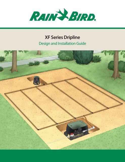
<strong>XF</strong> <strong>Series</strong> <strong>Dripline</strong><br />
Design and Installation Guide
Table of Contents<br />
Table of Contents<br />
Introduction.. . . . . . . . . . . . . . . . . . . . . . . . . . . . . . . . . . . . . . . . . . . . . . . . . . . . . . . . . . . . . . . . . 1<br />
About Rain Bird...............................................................1<br />
Step 1: Preparation for Design.................................................2<br />
Step 2: Determine the dripline specification. ..................................3<br />
Step 3: Determine the type of dripline layout, and lateral (row) spacing ........4<br />
Grid...................................................................4<br />
Lite .. . . . . . . . . . . . . . . . . . . . . . . . . . . . . . . . . . . . . . . . . . . . . . . . . . . . . . . . . . . . . . . . . . 5<br />
Lateral (Row) Spacing. ................................................6<br />
Step 4: Consider Maximum Lateral Run Lengths................................6<br />
Using Table 2 to Find Maximum Lateral Run Length.....................7<br />
Other Common Grid Layouts. .........................................8<br />
Step 5: Calculating Zone Water Requirements and Application Rates. ........ 10<br />
Zone Water Requirements .. . . . . . . . . . . . . . . . . . . . . . . . . . . . . . . . . . . . . . . . . . 10<br />
Application Rates.................................................... 10<br />
Step 6: Specifying Products in the Zone...................................... 11<br />
Control Zones.. . . . . . . . . . . . . . . . . . . . . . . . . . . . . . . . . . . . . . . . . . . . . . . . . . . . . . 11<br />
<strong>XF</strong> <strong>Series</strong> <strong>Dripline</strong>.................................................... 14<br />
<strong>XF</strong>-CHK <strong>Series</strong> <strong>Dripline</strong>............................................... 16<br />
Fittings. ............................................................ 18<br />
Tie-Down Stakes. ................................................... 19<br />
Air / Vacuum Relief Valves............................................ 19<br />
Manual Line Flushing Valve.. . . . . . . . . . . . . . . . . . . . . . . . . . . . . . . . . . . . . . . . . 20<br />
System Check Out & Test.. . . . . . . . . . . . . . . . . . . . . . . . . . . . . . . . . . . . . . . . . . . . . . . . . . . 20<br />
Preventative Maintenance. ................................................. 21<br />
Flushing. ........................................................... 21<br />
Winterizing. ........................................................ 21<br />
<strong>XF</strong> <strong>Series</strong> <strong>Dripline</strong> Design Guide
Introduction<br />
Introduction<br />
A low volume irrigation system typically applies water slowly, at low pressure, at or near the root zones of the plant<br />
material. Whether referred to as drip, micro-irrigation, or low volume, these systems feature emission devices that<br />
apply water in gallons per hour (GPH) as opposed to the gallons per minute (GPM) of a conventional overhead<br />
spray irrigation system.<br />
Low-volume irrigation can greatly reduce or eliminate water waste while promoting healthier plant growth because<br />
you can:<br />
• Match the water application to the specific need of the plant.<br />
• More closely match the application rate to the soil’s infiltration rate.<br />
• Apply water directly to the root zone to reduce overspray and evaporation.<br />
Low volume systems also reduce or eliminate runoff on walks and paved areas, and overspray onto windows, pavement,<br />
and walls. The Rain Bird ® Xerigation line of drip products offer a full range of water-savings choices for nonturfgrass<br />
landscape applications, including control zone components, dripline, distribution components, emission<br />
devices and tools.<br />
<strong>Dripline</strong> is a preferred method in many low volume irrigation applications. Rain Bird’s <strong>XF</strong> <strong>Series</strong> <strong>Dripline</strong> has inline<br />
emitters that provide pressure compensation for precise control of irrigation. <strong>XF</strong> <strong>Series</strong> dripline is made with<br />
advanced polymers that provide kink resistance and reduced coil memory for easier installation. With emitter flow<br />
rates of 0.6 and 0.9 GPH and emitter spacing at 12”, 18”, and 24”, the <strong>XF</strong> <strong>Series</strong> provides a full product line to meet<br />
the needs of any application.<br />
For complete performance and technical specifications, please see Rain Bird’s Landscape Irrigation Products Catalog<br />
or visit Rain Bird’s website at www.rainbird.com/drip. The website provides specifications and detail drawings in<br />
downloadable files.<br />
This guide covers the basics of design, installation, and maintenance of Rain Bird’s <strong>XF</strong> <strong>Series</strong> <strong>Dripline</strong>. Included are<br />
design steps, technical data, installation layouts, and design details to assist in the design of the more common<br />
dripline applications.<br />
About Rain Bird<br />
A privately held company founded in 1933, Rain Bird Corporation is the leading manufacturer and provider of irrigation<br />
products and services. Since its beginnings, Rain Bird has offered the industry’s broadest range of irrigation<br />
products for farms, golf courses, nurserys, sports arenas, commercial developments and homes in more than 130<br />
countries around the world. With the broadest product line in the industry, architects, designers, and contractors<br />
recognize Rain Bird as the industry leader in irrigation solutions.<br />
Rain Bird is committed to The Intelligent Use of Water. It is our legacy to design and manufacture only those<br />
products of the highest value, quality, and efficient application of water. We work for long-term, responsible partnerships<br />
with our customers and our suppliers. This is who we are, and this is how we wish to be perceived in the<br />
irrigation industry and our communities.<br />
<strong>XF</strong> <strong>Series</strong> <strong>Dripline</strong> Design Guide 1
Step 1: Preparation for Design<br />
<strong>XF</strong> <strong>Series</strong> <strong>Dripline</strong> is excellent for irrigating dense planting and flower beds, shrubs, trees, and ground cover.<br />
The slow and even flowing dripline provides a natural release of water to the plant life without runoff or overspray.<br />
When designed correctly, a dripline system combines an effective way to irrigate plants by providing water directly<br />
to the root zone while providing the most efficient use of water.<br />
Rain Bird offers two types of <strong>XF</strong> <strong>Series</strong> <strong>Dripline</strong>; <strong>XF</strong> and <strong>XF</strong>-CHK. Both types feature Rain Bird’s exclusive advanced<br />
polymer tubing that provides the most flexible and kink resistant dripline available. Both driplines also feature<br />
pressure compensation, resistance to chemicals, UV damage, and algae growth, and can be used with 17mm insert<br />
fittings. <strong>XF</strong>-CHK <strong>Dripline</strong> has the added feature of a check valve that can hold back up to 14 feet of head. <strong>XF</strong>-CHK’s<br />
hold back leads the industry and makes it the perfect solution for terrain with elevation changes such as slopes.<br />
Step 1 Preparation for Design<br />
●<br />
Designing a dripline system follows many of the same rules as a spray and rotor system. Point of water source connection,<br />
static and operating pressures, flow rates, and plant material to be irrigated are usually similar.<br />
A dripline system when properly designed will deliver full irrigation coverage to the planted area. A dripline system<br />
is normally divided into zones. A typical zone contains a water source, a control zone (valve, filter, and pressure<br />
regulator), and the dripline with connection fittings.<br />
During the preparation for design you will gather essential information to design the dripline system.<br />
• Obtain or draw a scaled plan of the site to be irrigated.<br />
• Identify all of the slopes on the plan.<br />
• Determine the types of plants to be irrigated (groundcover, shrubs, plants, and trees)<br />
• Identify the type of soil (sand, loam, or clay)<br />
• Identify the type of water from the water source (potable, non potable, well, pump, etc.)<br />
• Identify static and operating pressures, and volume available from the water source.<br />
2<br />
<strong>XF</strong> <strong>Series</strong> <strong>Dripline</strong> Design Guide
Step 2: Determine the dripline specification<br />
Step 2 Determine the dripline specification<br />
●<br />
The objective of a well designed dripline system is to create an even wetting pattern of water in the soil throughout<br />
the planting zone. There are four factors to consider for planting areas to create an even wetting pattern:<br />
• Soil types (Clay, Loam, Sand)<br />
• <strong>Dripline</strong> emitter flow rate (.6 GPH or .9 GPH)<br />
• <strong>Dripline</strong> emitter spacing (12”, 18”, or 24”)<br />
• Lateral (row) spacing of the dripline<br />
To determine the specification for the emitter flow rate and emitter spacing for the <strong>XF</strong> <strong>Series</strong> dripline (also can be<br />
used for LD dripline) go to Table 1 under Shrub and Ground Cover. Follow the column under the proper soil type for<br />
your application to find the emitter flow and emitter spacing. For example, if you have loam soil you would choose<br />
<strong>XF</strong> <strong>Series</strong> dripline with 0.9 GPH emitter flow and with 18" emitter spacing (each emitter will deliver 0.9 GPH and the<br />
emitters mounted inside the tubing are spaced 18" apart).<br />
Table 1 also provides a range for the lateral spacing of the dripline. For the example, loam soil recommends a lateral<br />
spacing of 18” – 24”. Lateral spacing will be discussed in Step 3 where it will show how to calculate a more precise<br />
spacing.<br />
Table 1: <strong>XF</strong> <strong>Series</strong> <strong>Dripline</strong> Row Spacing recommendation tables<br />
Shrub and Ground Cover<br />
Clay Soil Loam Soil Sandy Soil<br />
Emitter Flow 0.6 gph 0.9 gph 0.9 gph<br />
Emitter Spacing 24" 18" 12"<br />
<strong>XF</strong> <strong>Series</strong> <strong>Dripline</strong> Lateral Spacing 18" - 24" 18" - 24" 12" - 20"<br />
If you are not quite sure on the soil type, here is a test you can use by squeezing the soil in your hand:<br />
Clay – When dry it forms hard clumps. When damp it is flexible and can be molded into shapes.<br />
Loam – A moderate sand or dirt and very little clay. When dry it breaks easily. When wet it forms a lump.<br />
Sand – Soil particles are loose, sandy grains. When dry it will fall apart when you open your hand. When damp it will<br />
form a lump but it will crumble easily when touched.<br />
Soil Preparation<br />
<strong>Dripline</strong> relies on the soil to spread an even wetting pattern of water throughout the planting area. Preparation of<br />
the soil is important to achieve an even wetting pattern. The more homogeneous the soil in the planting area, the<br />
more uniform the water distribution. It is recommended that compacted soil be tilled to an 8” to 12” (20 – 30 cm)<br />
depth and then irrigate to field capacity prior to planting.<br />
<strong>XF</strong> <strong>Series</strong> <strong>Dripline</strong> Design Guide 3
Step 3: Determine the type of dripline layout, and lateral (row) spacing<br />
Step 3 Determine the type of dripline layout, and lateral (row) spacing<br />
●<br />
There are two types of layouts that are recommended; Grid and Lite. Both will provide appropriate irrigation, but<br />
the Grid layout has some benefits over the Lite layout.<br />
Grid<br />
The grid layout is primarily used for dense plantings. The layout uses supply and exhaust headers with rows of<br />
dripline connected at each end. The supply and exhaust header forms a continuous loop where all rows of dripline<br />
are being supplied from both ends.<br />
<strong>XF</strong> <strong>Series</strong> Grid Layout with End Feed<br />
Control Zone<br />
in Valve Box<br />
Inline Emitters<br />
<strong>XF</strong> <strong>Series</strong> <strong>Dripline</strong><br />
Laterals<br />
Wetted Area<br />
Air Relief Valve<br />
Kit in Valve Box<br />
Lateral lines<br />
Flush Valve<br />
Compression or<br />
Insert Fittings<br />
Lateral spacing<br />
<strong>Dripline</strong> Lateral Run Length<br />
From Water Source<br />
Design Considerations:<br />
PVC, polyethylene<br />
tubing, or dripline<br />
header<br />
• Headers should be spaced 2” – 4” from hardscapes or other planting zones.<br />
• Headers may be PVC, polyethylene tubing, or dripline.<br />
• Lateral spacing is a design consideration and can be calculated as shown on page 6 in Example 1: How to<br />
Calculate Equal Lateral (Row) Spacing.<br />
• The lateral run length should not exceed the maximum lateral length shown in Table 2 on page 10.<br />
• Installations using dripline without a check valve should use an air/vacuum relief valve at a high point in the<br />
system to avoid back siphoning material into the emitters.<br />
• Manual flush should be installed at a low point in the exhaust header.<br />
Benefits of the Grid layout<br />
• A better distribution of flow ensures water is being delivered downstream of any break in the laterals. Also,<br />
repair of line breaks are easier.<br />
• A better solution for larger planting zones.<br />
4<br />
<strong>XF</strong> <strong>Series</strong> <strong>Dripline</strong> Design Guide
Step 3: Determine the type of dripline layout, and lateral (row) spacing<br />
Lite<br />
The Lite layout is one continuous loop that weaves back and forth throughout the zone in evenly spaced laterals<br />
(rows).<br />
<strong>XF</strong> <strong>Series</strong> Lite Layout with End Feed<br />
Air Relief Valve<br />
Kit in Valve Box<br />
Flush Valve<br />
Inline Emitters<br />
Control Zone<br />
in Valve Box<br />
Wetted<br />
Area<br />
Lateral spacing<br />
<strong>XF</strong> <strong>Series</strong> <strong>Dripline</strong><br />
From Water Source<br />
Insert or<br />
Compression<br />
Fitting<br />
Design Considerations:<br />
• Space the tubing 2” – 4” from hardscapes and other planting zones.<br />
• Lateral spacing is a design consideration and can be calculated as shown on page 6 in Example 1: How to<br />
Calculate Equal Lateral (Row) Spacing.<br />
• Because water is split into two separate paths that meet in the middle, the total continuous loop length of<br />
dripline should not exceed the twice the maximum lateral run length, which will be considered in Step 4.<br />
• Installations using dripline without a check valve should use an air/vacuum relief valve at a high point in the<br />
system to avoid back siphoning material into the emitters.<br />
• Manual flush should be installed at the mid point of the Lite layout.<br />
Benefits of the Lite layout<br />
• The fastest and easiest method with no supply or exhaust headers.<br />
<strong>XF</strong> <strong>Series</strong> <strong>Dripline</strong> Design Guide 5
Step 3: Determine the type of dripline layout, and lateral (row) spacing<br />
Lateral (Row) Spacing<br />
A range of lateral row spacing (Ex. 18” – 24”, loam soil) was provided in Table 1. But to calculate equal lateral row<br />
spacing for the design application, you need to know the width of the application and then use the calculation as<br />
shown in Example 1.<br />
Example 1: How to Calculate Equal Lateral (Row) Spacing<br />
• Application width = 8’ (this would normally<br />
come from your scaled plan gathered in<br />
Step 1).<br />
• Convert into inches: 8’ x 12” = 96”<br />
• It is recommended to space dripline 2” from<br />
hardscapes and 4” from separate planting<br />
zones. In this example there are hardscapes<br />
on each side of the planting zone. Remove<br />
the hardscape spacing on each side from<br />
the total width: 96” – 4” = 92”<br />
• From the previous example, the range of<br />
lateral row spacing from Table 1 is<br />
18” – 24”. Use the low end of the range (in<br />
this case 18”) and calculate the number<br />
of spaces between rows: 92” ÷ 18” = 5.1.<br />
Round to get whole spaces. Round up if the<br />
decimal is 0.5 or higher, round down if it is<br />
less than 0.5. In this case you should round<br />
down to 5 whole spaces between rows.<br />
• Calculate the equal lateral row spacing:<br />
92” ÷ 5 = 18.4”<br />
• Calculate the number of dripline rows by<br />
adding 1 to the number of spaces between<br />
rows: 5 + 1 = 6 dripline rows.<br />
18.4”<br />
Application Width<br />
8 feet<br />
96 inches<br />
18.4” 18.4”<br />
18.4” 18.4”<br />
<strong>XF</strong> <strong>Series</strong> <strong>Dripline</strong><br />
2”<br />
from<br />
hardscape<br />
Step 4 Consider Maximum Lateral Run Lengths<br />
●<br />
The maximum lateral run length is an important design consideration in a dripline system. The maximum lateral<br />
run length increases with higher inlet pressures to the dripline. For a given inlet pressure, the maximum lateral<br />
run length is the longest length of dripline that the manufacturer has determined will provide the rated emitter<br />
flow rate. It takes into account pressure losses for the flow rate from emitters in the lateral run and the friction loss<br />
through the tubing. Lengths of lateral runs above this maximum length will cause some emitters at the end of the<br />
runs to have lower flow rates. This may cause plants to receive less than the appropriate watering requirements.<br />
Therefore it is important that the longest lateral run in the dripline design not exceed the maximum lateral run<br />
length for the given inlet pressure of the system.<br />
The maximum lateral run length may also be important when you have longer planting zones like medians, where<br />
you can reduce the number of zones by using longer laterals. The center feed grid system on page 11 is a good<br />
layout for these applications.<br />
6<br />
<strong>XF</strong> <strong>Series</strong> <strong>Dripline</strong> Design Guide
Step 4: Consider Maximum Lateral Run Lengths<br />
The maximum lateral run length is determined by the inlet pressure to the dripline, the number of emitters in the<br />
run, the emitter flow rate, and the lowest pressure that the emitter performs without reducing its rated flow. This can<br />
be a somewhat complicated calculation, but it has been made simple with the information provided in Table 2.<br />
Using Table 2 to Find Maximum Lateral Run Length<br />
You need to know the operating pressure from Step 1 and the dripline specification from Step 2 to determine the<br />
maximum lateral run length. First, take the operating pressure from Step 1 and use the operating pressure or 45<br />
psi, which ever is lower. Now go to Table 2 and using that pressure and the emitter spacing and emitter flow rate<br />
from your Step 2 dripline specification, find the maximum lateral run length. The pressure is found on the left side<br />
column of the table, the emitter spacing is in the row across the top of the table, and the emitter flow rate is in the<br />
row on the bottom of the table. For your application, find where these three intersect to determine the maximum<br />
lateral run length. For example, an inlet pressure of 40 psi using <strong>XF</strong> <strong>Series</strong> dripline with 0.9 GPH emitter flow rate and<br />
18” emitter spacing yields a maximum lateral run length of 428 feet.<br />
Table 2: <strong>XF</strong> <strong>Series</strong> <strong>Dripline</strong> (both <strong>XF</strong> and <strong>XF</strong>-CHK) - Maximum Length of a Single Lateral (feet)<br />
<strong>XF</strong> <strong>Series</strong> <strong>Dripline</strong> - Maximum Length of a Single Lateral (feet)<br />
<strong>XF</strong> <strong>Series</strong> Emitter Spacing<br />
Inlet Pressure (psi)<br />
12" 18" 24"<br />
15 255’ 194’ 357’ 273’ 448’ 343’<br />
20 291’ 220’ 408’ 313’ 514’ 394’<br />
25 325’ 249’ 458’ 351’ 577’ 443’<br />
30 350’ 266’ 494’ 378’ 622’ 478’<br />
35 371’ 285’ 525’ 402’ 661’ 508’<br />
40 396’ 302’ 560’ 428’ 705’ 541’<br />
45 415’ 318’ 587’ 449’ 739’ 567’<br />
50 434’ 333’ 614’ 470’ 775’ 594’<br />
55 451’ 346’ 639’ 488’ 807’ 619’<br />
Emitter Flow Rate (GPH) 0.6 0.9 0.6 0.9 0.6 0.9<br />
<strong>XF</strong> <strong>Series</strong> <strong>Dripline</strong> - Maximum Length of a Single Lateral (meters)<br />
<strong>XF</strong> <strong>Series</strong> Emitter Spacing<br />
Inlet Pressure (bar)<br />
30.5 cm 45.7 cm 61.0 cm<br />
1.0 78m 59m 109m 83m 137m 105m<br />
1.4 89m 67m 124m 95m 157m 120m<br />
1.7 99m 76m 140m 107m 176m 135m<br />
2.1 107m 81m 151m 115m 190m 146m<br />
2.4 113m 87m 160m 123m 201m 155m<br />
2.8 121m 92m 171m 131m 215m 165m<br />
3.1 126m 97m 179m 137m 225m 173m<br />
3.4 132m 101m 187m 143m 236m 181m<br />
3.8 137m 105m 195m 149m 246m 189m<br />
Emitter Flow Rate (LPH) 2.3 3.5 2.3 3.5 2.3 3.5<br />
Occasionally, plants within the <strong>XF</strong> <strong>Series</strong> <strong>Dripline</strong> watering grid will require supplemental irrigation. Supplemental<br />
connections are normally done with a self piercing barb connector into the dripline with ¼” tubing feeding a Xeri-<br />
Bug or PC Module emitter that irrigates the plant. If you have supplemental connections, the rule of thumb is to<br />
reduce 2 feet from the maximum lateral run for every 1 GPH of flow to the supplemental emitters.<br />
<strong>XF</strong> <strong>Series</strong> <strong>Dripline</strong> Design Guide 7
Other Common Grid Layouts<br />
Other Common Grid Layouts<br />
Manual Line Flushing<br />
Center Feed Layout<br />
• Where layout flexibility exists, it is recommended<br />
that Center Feed layouts be used.<br />
This allows for the most even flow of water<br />
through the zone.<br />
• Center Feed layouts also potentially allow<br />
you to increase the size of the zone by<br />
providing lateral runs on both sides of the<br />
header.<br />
• Center Feed layouts are an excellent<br />
option for median strips, road sides, and<br />
other homogenous planting zones.<br />
PVC or Poly<br />
Exhaust Header<br />
Insert or<br />
Compression Fittings<br />
Control Zone<br />
PVC or Poly<br />
Supply Header<br />
Area Perimeter<br />
Air Relief Valve<br />
Perimeter Laterals<br />
2” to 4” from edge<br />
Manual Line Flushing<br />
Branching Out or Joining Row Layouts<br />
• When branching out from a supply header with <strong>XF</strong> <strong>Series</strong> dripline, maximum lateral run length should be<br />
considered. Add up all the “branched out” dripline and check it against the maximum lateral run length listed<br />
in Table 2.<br />
• When joining lateral rows from a supply header, check only the longest lateral against the maximum lateral<br />
run length listed in Table 2.<br />
Supply Supply Header Header<br />
Supply Supply Header Header<br />
Branching Out<br />
with <strong>XF</strong> <strong>Series</strong><br />
Laterals<br />
Joining Rows<br />
with <strong>XF</strong> <strong>Series</strong><br />
Laterals<br />
Total Total the the combined<br />
length length of these of these <strong>XF</strong> <strong>Series</strong> <strong>XF</strong> <strong>Series</strong><br />
<strong>Dripline</strong> <strong>Dripline</strong> laterals laterals and and<br />
compare compare it against it against the the<br />
maximum lateral lateral length length<br />
allowed allowed in Table in Table 2. 2.<br />
Check Check longest longest lateral lateral<br />
against against Table Table 2 for 2 for<br />
maximum lateral lateral<br />
length. length.<br />
Exhaust Exhaust Header Header<br />
Exhaust Exhaust Header Header<br />
8<br />
<strong>XF</strong> <strong>Series</strong> <strong>Dripline</strong> Design Guide
Other Common Grid Layouts<br />
Elevation Changes - Slope Layout<br />
The design of the dripline system should account<br />
for the slopes, berms, banks, or depressions on the<br />
site since runoff may occur with slopes of 3% or<br />
greater. <strong>XF</strong>–CHK <strong>Series</strong> dripline is recommended<br />
for slope layouts as it provides a check valve that<br />
will hold back water keeping the lines full when the<br />
system is turned off. As you go up a slope, water<br />
exerts 0.43 psi pressure on the lowest lateral run for<br />
every 1 foot of elevation change. The <strong>XF</strong>–CHK has a<br />
check valve with the highest hold back pressure in<br />
the industry, able to handle a 14 foot vertical elevation<br />
change. This assures that after the system<br />
shuts down, the emitters will not continue to drain<br />
leading to puddling and runoff.<br />
• <strong>Dripline</strong> laterals should run perpendicular to<br />
the slope whenever possible.<br />
Top of Slope<br />
Top Separated from Toe<br />
Top 2/3<br />
Normal<br />
Spacing<br />
Toe of Slope<br />
Bottom 1/3<br />
spacing<br />
plus 25%<br />
• Lateral row spacing should be normal spacing<br />
(as per the calculation in Step 3, page 9)<br />
within the top two-thirds of the slope.<br />
• Lateral row spacing should be 25% greater<br />
within the bottom one-third of the slope.<br />
• For more than 14 feet of elevation change,<br />
either split the slope into separate zones or<br />
install an inline check valve in the supply and<br />
exhaust header.<br />
Trees – Double Loop layout<br />
When watering trees it is important that the tree<br />
rootball receives adequate water, while allowing<br />
for the tree’s needs as it grows. When trees<br />
are transplanted, the soil in the rootball and the<br />
native soil where it is being planted are usually<br />
different. Therefore the dripline layout needs<br />
to ensure that both soils are being irrigated because<br />
water will not migrate across soil types.<br />
• A double loop layout is recommended for<br />
trees. The first loop should be close to the<br />
rootball, while the second outside loop<br />
should be in line with the tree’s canopy<br />
when it has matured.<br />
Insert Cross<br />
Insert Tee<br />
<strong>XF</strong> <strong>Series</strong> <strong>Dripline</strong> Design Guide 9
Step 5: Calculating Zone Water Requirements and Application Rates<br />
Step 5 Calculating Zone Water Requirements and Application Rates<br />
●<br />
Zone Water Requirements<br />
After the dripline layout design is complete, you will need to identify total zone flow. This is used to help determine<br />
mainline, supply and exhaust header, and control zone (valve, filter, & regulator) selection.<br />
• Calculating zone water requirements can be done by adding up the total dripline line in the zone. Convert<br />
the total dripline to hundreds of feet (650 feet would be 6.5 in hundreds of feet).<br />
• Multiply total dripline in hundreds of feet by the flow per 100 feet for your specified dripline. This can be<br />
found in Table 3. To read the table, select the emitter flow rate in the row across the top (0.6 GPH or 0.9 GPH)<br />
and then select the emitter spacing in the left column (12”, 18”, or 24”). Follow emitter flow rate down and<br />
emitter spacing across to find the flow per 100 feet for the <strong>XF</strong> <strong>Series</strong> dripline specified.<br />
• For example, for a zone that has 650 feet of 0.9 GPH emitters and 18” emitter spacing, the calculation would<br />
be 6.50 x 1.02 gpm = 6.6 gpm for the zone.<br />
• Supply lines and headers should be sized to provide the flow to the zone without exceeding 5 feet per second<br />
velocity. This can be done using the zone water requirement and referencing information on the appropriate<br />
piping located at www.rainbird.com/reference or in the back reference section in the Rain Bird catalog.<br />
Table 3 - <strong>XF</strong> <strong>Series</strong> <strong>Dripline</strong> Flow (per 100 feet)<br />
Emitter Spacing 0.6 GPH Emitter 0.9 GPH Emitter<br />
12" 61.0 GPH 1.02 GPM 92.0 GPH 1.53 GPM<br />
18" 41.0 GPH 0.68 GPM 61.0 GPH 1.02 GPM<br />
24" 31.0 GPH 0.51 GPM 46.0 GPH 0.77 GPM<br />
Application Rates<br />
The application rate is the rate that the <strong>XF</strong> <strong>Series</strong> <strong>Dripline</strong> applies water to the soil. This is used to determine run<br />
times for the zone based on the plants watering requirements. Table 4 is provided to make it easy to determine application<br />
rates for every model of <strong>XF</strong> <strong>Series</strong> <strong>Dripline</strong> (also LD <strong>Dripline</strong>) when using common row spacing (12” – 24”).<br />
The table is divided into two sections, a 0.6 GPH emitter flow section and a 0.9 GPH emitter flow section. Go to the<br />
section for the specified emitter flow rate and find in the left hand column the specified emitter spacing. Now find<br />
the lateral row spacing across the top of the table. Follow the lateral row spacing column down and the emitter<br />
spacing row across until the two meet. This is the application rate in inches per hour. For example, a 0.6 GPH emitter<br />
flow rate with 18” emitter spacing and 18” lateral row spacing has an application rate of 0.43 inches per hour.<br />
Table 4 - <strong>XF</strong> <strong>Series</strong> <strong>Dripline</strong> Application Rate (inches per hour)<br />
Lateral Row Spacing<br />
Emitter Spacing 12" 13" 14" 15" 16" 17" 18" 19" 20" 22" 24"<br />
0.6 GPH Emitter Flow (in inches per hour)<br />
12" 0.96 0.89 0.83 0.77 0.72 0.68 0.64 0.61 0.58 0.53 0.48<br />
18" 0.64 0.59 0.55 0.51 0.48 0.45 0.43 0.4 0.39 0.35 0.32<br />
24" 0.48 0.44 0.41 0.39 0.36 0.34 0.32 0.3 0.29 0.26 0.24<br />
0.9 GPH Emitter Flow (in inches per hour)<br />
12" 1.44 1.33 1.24 1.16 1.08 1.02 0.96 0.91 0.87 0.79 0.72<br />
18" 0.96 0.89 0.83 0.77 0.72 0.68 0.64 0.61 0.58 0.53 0.48<br />
24" 0.72 0.67 0.62 0.58 0.54 0.51 0.48 0.46 0.43 0.39 0.36<br />
10<br />
<strong>XF</strong> <strong>Series</strong> <strong>Dripline</strong> Design Guide
Step 6: Specifying Products in the Zone<br />
For designs that are not in Table 4, use the following calculation.<br />
Application Rate (inches per hour)<br />
231.1 x Emitter Flow Rate (GPH)<br />
<strong>Dripline</strong> Lateral Row Spacing (inches) x Emitter Spacing (inches)<br />
Example:<br />
Emitter Flow Rate = 0.9 GPH<br />
Emitter Spacing = 18”<br />
<strong>Dripline</strong> Lateral Row Spacing = 18.4”<br />
Calculation:<br />
231.1 x 0.9 GPH<br />
18.4 inches x 18 inches<br />
= 0.63 inches per hour<br />
Step 6 Specifying Products in the Zone<br />
●<br />
After completing the dripline layout design, you’ll need to determine the other remaining products that will be in<br />
the zone. The products that make up a dripline line zone are normally the control zone (an assembled unit that<br />
provides a valve, filter, and regulator), fittings that connect the dripline, and flush and air relief valves that allow for<br />
flushing water or bleeding off trapped air.<br />
Control Zones<br />
A control zone provides the proper water flow to a zone, filtration to assure contaminents are removed that can<br />
plug emitters, and pressure regulation for optimum performance of the dripline system. With the broadest product<br />
line in the industry and easy installation and maintenance that will save time, Rain Bird control zones are the choice<br />
for any project. Features and benefits include:<br />
• Durable and reliable low, medium, and high flow valves. Rain Bird's low flow valve leads the industry handling<br />
flows down to 0.2 gpm without weeping. See video at www.rainbird.com/lowflow.<br />
• 200 mesh high capacity stainless steel filters that will catch grit and debris that could clog emitters causing a<br />
reduction in water flow that could damage plants.<br />
• Filters that are simple to remove from the body and are easily cleaned under a faucet or in a pail of<br />
clean water.<br />
• Back flush self cleaning filters that purge the debris from the filter during the start up of the system (Model<br />
number ends with a BF).<br />
• Commercial high capacity filter that has a maintenance indicator that tells you when it needs cleaning.<br />
• Pressure regulators that reduce operating pressure to 30 psi or 40 psi.<br />
• Compact size with the filter and regulator combined in the same housing to reduce parts and potential leaking<br />
problems. Compact size makes the control zone easier to install and it can allow for fitting more control<br />
zones in a valve box.<br />
<strong>XF</strong> <strong>Series</strong> <strong>Dripline</strong> Design Guide 11
Control Zones<br />
The Control Zone Pyramid (shown below) provides an easy to use selection guide for identifying the proper control<br />
zone for your application.<br />
• Category 1 - Residential/Light Commercial Low Flow: 0.2 – 5 gpm, 30 psi pressure regulation<br />
• Category 2 - Residential/Light Commercial Medium Flow: 3 – 15 gpm, 40 psi pressure regulation<br />
• Category 3 - Commercial Medium Plus: 3 – 20 gpm, 40 psi pressure regulation<br />
• Category 4 - Commercial High Flows: 15 – 40 gpm, 40 psi pressure regulation<br />
Control Zone Pyramid<br />
CATEGORY 4<br />
XCZ-150-COM<br />
Commerical High Flow: 15–40 gpm<br />
CATEGORY 3<br />
XCZ-100-B-COM<br />
Commercial Medium Plus: 3–20 gpm<br />
CATEGORY 2<br />
XCZ-100-PRF XCZ-100-PRF-BF XACZ-100-PRF XACZ-100-PRF-BF<br />
Residential/Light Commercial Medium Flow: 3–15 gpm<br />
CATEGORY 1<br />
XCZ-075-PRF XCZ-075-PRF-BF XCZ-LF-100-PRF XACZ-075-PRF XACZ-075-PRF-BF<br />
Residential/Light Commercial Low Flow: 0.2–5 gpm<br />
12<br />
<strong>XF</strong> <strong>Series</strong> <strong>Dripline</strong> Design Guide
Control Zones<br />
When selecting a control zone for your design, start by considering both the pressure needed for the longest lateral<br />
run in your layout and the zone water requirements.<br />
• Take the longest lateral run in your design and go to Table 2 on page 10. Using the specified dripline, find<br />
the emitter spacing (12”, 18”, and 24”) shown in the top row and the emitter flow rate (0.6 or 0.9) shown in the<br />
bottom row to narrow the selection to one column. Within the column, find the length that is just greater<br />
than your longest lateral run. At this length, follow the row across to the left to find the inlet pressure. This<br />
is the minimum inlet pressure to support the flow performance for the longest lateral run. For example, if<br />
your longest lateral run is 280’ for a specified dripline using 0.9 GPH emitters and 12” spacing, the minimum<br />
inlet pressure would be 35 psi. Therefore the regulated pressure supplied through the control zone should<br />
provide 35 psi or greater pressure.<br />
• Take the pressure that you just found in Table 2 ( 35 psi for the example) and the zone water requirements<br />
from your Step 5 calculation (6.6 gpm for the example), and refer to the control zone information on page<br />
12 to select the appropriate control zone. Identify the category of control zones that will meet your pressure<br />
regulation and flow requirements for the design. For the example, 35 psi pressure and 6.6 gpm flow would<br />
narrow the selection to category 2 and 3. Both category 2 and 3 show control zones that have 40 psi regulators<br />
and flow rates up to 15 gpm and 20 gpm respectively.<br />
• Now that you have identified the control zones that will provide the pressure and flow rate performance<br />
needed in your design, you can now evaluate the different features of the control zones in the category to<br />
select the right control zone for your application.<br />
• The Commercial Control Zones have a large capacity filter with a maintenance indicator that changes from<br />
green to red when it requires cleaning.<br />
• Control Zones whose model number ends with BF have back flush self cleaning filters that purge the debris<br />
from the filter every watering cycle.<br />
• Control Zones whose model number start with XACZ have low flow anti-siphon valves that have an atmospheric<br />
vacuum breaker for backflow prevention.<br />
• It is recommended that for low flows less than 3 gpm, control zones using Rain Bird’s low flow valve in category<br />
1 be used. This low flow valve is designed to eliminate weeping at low flow rates. View a video on this<br />
valve at www.rainbird.com/lowflow.<br />
Filters are an integral component in a dripline system. <strong>Dripline</strong> systems should not be designed without proper<br />
filtration. Filtration is required to eliminate contaminants in the water that could plug the small drip outlets on the<br />
emitters. All Rain Bird control zones come with a 200 mesh stainless steel filter, more than adequate to handle filtration<br />
requirement of the <strong>XF</strong> <strong>Series</strong> dripline.<br />
For more information on Rain Bird control zones, consult the website at www.rainbird.com/drip/products/control.<br />
You can point and click on a control zone in the pyramid for detailed information. Otherwise refer to a Rain Bird<br />
product catalog.<br />
<strong>XF</strong> <strong>Series</strong> <strong>Dripline</strong> Design Guide 13
<strong>XF</strong> <strong>Series</strong> <strong>Dripline</strong><br />
<strong>XF</strong> <strong>Series</strong> <strong>Dripline</strong><br />
Made with advanced polymers, the <strong>XF</strong> <strong>Series</strong> dripline is the most flexible dripline available. The <strong>XF</strong> <strong>Series</strong> provides<br />
kink resistance and reduced coil memory making installations easier and faster. With easier installations that save<br />
you time along with superior performance with no kinking problems, <strong>XF</strong> <strong>Series</strong> is the choice for all dripline projects.<br />
Applications:<br />
• Surface installations<br />
• Planting & flower beds, trees, and shrubs<br />
• Narrow, curved, and tight areas.<br />
• All irrigation surfaces except slopes<br />
Specifications:<br />
• Pressure Range: 8.5 to 60 psi (0.7 to 4.1 bar)<br />
• Flow Rates: 0.6 and 0.9 gph (2.3 l/h and 3.5 l/h)<br />
• Emitter Spacing: 12”, 18”, or 24”<br />
• Required Filtration: 120 mesh<br />
• Dual-layered tubing (brown over black) provides<br />
unmatched resistance to chemicals, UV damage,<br />
and algae growth.<br />
• Use with 17 mm insert fittings or Easy Fit compression<br />
fittings<br />
<strong>XF</strong> <strong>Series</strong> <strong>Dripline</strong><br />
<strong>XF</strong> <strong>Series</strong> <strong>Dripline</strong> Offers Improved<br />
Flexibility for Kink Resistance and<br />
Easy Installation<br />
Dimensions:<br />
• OD: 0.634” (16.1 mm)<br />
• ID: 0.536” (13.6 mm)<br />
• Wall Thickness: 0.049” (1.2 mm)<br />
How To Specify<br />
<strong>XF</strong>D - 09 - 12 - 100<br />
Model<br />
<strong>XF</strong><br />
<strong>Dripline</strong><br />
Length of Tubing<br />
100 = 100’ (30.5 m)<br />
250 = 250’ (76.2 m)<br />
500 = 500’ (152.4 m)<br />
Emitter Spacing<br />
12 = 12” (30.5 cm)<br />
18 = 18” (45.7 cm)<br />
24 = 24” (61.0 cm)<br />
Flow Rate<br />
06 = .61 gph (2.3 l/h)<br />
09 = .92 gph (3.5 l/h)<br />
14<br />
<strong>XF</strong> <strong>Series</strong> <strong>Dripline</strong> Design Guide
<strong>XF</strong> <strong>Series</strong> <strong>Dripline</strong><br />
<strong>XF</strong> <strong>Series</strong> <strong>Dripline</strong> Models<br />
<strong>XF</strong> <strong>Series</strong> <strong>Dripline</strong> Models<br />
METRIC<br />
Model Flow<br />
gph<br />
Spacing<br />
in.<br />
Coil Length<br />
ft.<br />
<strong>XF</strong>D-06-12-100 0.60 12 100<br />
<strong>XF</strong>D-06-12-250 0.60 12 250<br />
<strong>XF</strong>D-06-12-500 0.60 12 500<br />
<strong>XF</strong>D-06-18-100 0.60 18 100<br />
<strong>XF</strong>D-06-18-250 0.60 18 250<br />
<strong>XF</strong>D-06-18-500 0.60 18 500<br />
<strong>XF</strong>D-06-24-100 0.60 24 100<br />
<strong>XF</strong>D-06-24-250 0.60 24 250<br />
<strong>XF</strong>D-06-24-500 0.60 24 500<br />
<strong>XF</strong>D-09-12-100 0.90 12 100<br />
<strong>XF</strong>D-09-12-250 0.90 12 250<br />
<strong>XF</strong>D-09-12-500 0.90 12 500<br />
<strong>XF</strong>D-09-18-100 0.90 18 100<br />
<strong>XF</strong>D-09-18-250 0.90 18 250<br />
<strong>XF</strong>D-09-18-500 0.90 18 500<br />
<strong>XF</strong>D-09-24-100 0.90 24 100<br />
<strong>XF</strong>D-09-24-250 0.90 24 250<br />
<strong>XF</strong>D-09-24-500 0.90 24 500<br />
Model Flow<br />
l/h<br />
Spacing<br />
cm<br />
Coil Length<br />
m<br />
<strong>XF</strong>D-06-12-100 2.30 30.5 30.5<br />
<strong>XF</strong>D-06-12-250 2.30 30.5 76.5<br />
<strong>XF</strong>D-06-12-500 2.30 30.5 152.9<br />
<strong>XF</strong>D-06-18-100 2.30 45.7 30.5<br />
<strong>XF</strong>D-06-18-250 2.30 45.7 76.5<br />
<strong>XF</strong>D-06-18-500 2.30 45.7 152.9<br />
<strong>XF</strong>D-06-24-100 2.30 61.0 30.5<br />
<strong>XF</strong>D-06-24-250 2.30 61.0 76.5<br />
<strong>XF</strong>D-06-24-500 2.30 61.0 152.9<br />
<strong>XF</strong>D-09-12-100 3.50 30.5 30.5<br />
<strong>XF</strong>D-09-12-250 3.50 30.5 76.5<br />
<strong>XF</strong>D-09-12-500 3.50 30.5 152.9<br />
<strong>XF</strong>D-09-18-100 3.50 45.7 30.5<br />
<strong>XF</strong>D-09-18-250 3.50 45.7 76.5<br />
<strong>XF</strong>D-09-18-500 3.50 45.7 152.9<br />
<strong>XF</strong>D-09-24-100 3.50 61.0 30.5<br />
<strong>XF</strong>D-09-24-250 3.50 61.0 76.5<br />
<strong>XF</strong>D-09-24-500 3.50 61.0 152.9<br />
<strong>XF</strong> <strong>Series</strong> <strong>Dripline</strong> Maximum Lateral Lengths (Feet)<br />
Inlet Pressure Maximum Lateral Length (feet)<br />
psi 12” Spacing 18” Spacing 24” Spacing<br />
Nominal Flow (gph): Nominal Flow (gph): Nominal Flow (gph):<br />
.6 .9 .6 .9 .6 .9<br />
15 255 194 357 273 448 343<br />
20 291 220 408 313 514 394<br />
25 325 249 458 351 577 443<br />
30 350 266 494 378 622 478<br />
35 371 285 525 402 661 508<br />
40 396 302 560 428 705 541<br />
45 415 318 587 449 739 567<br />
50 434 333 614 470 775 594<br />
55 451 346 639 488 807 619<br />
<strong>XF</strong> <strong>Series</strong> <strong>Dripline</strong> Maximum Lateral Lengths (Meters)<br />
METRIC<br />
Inlet Pressure Maximum Lateral Length (Meters)<br />
bar 30.5 cm 45.7 cm 61.0 cm<br />
Nominal Flow (l/h): Nominal Flow (l/h): Nominal Flow (l/h):<br />
2.3 3.5 2.3 3.5 2.3 3.5<br />
1.0 78 59 109 83 137 105<br />
1.4 89 67 124 95 157 120<br />
1.7 99 76 140 107 176 135<br />
2.1 107 81 151 115 190 146<br />
2.4 113 87 160 123 201 155<br />
2.8 121 92 171 131 215 165<br />
3.1 126 97 179 137 225 173<br />
3.4 132 101 187 143 236 181<br />
3.8 137 105 194 148 245 188<br />
<strong>XF</strong> <strong>Series</strong> <strong>Dripline</strong> Design Guide 15
<strong>XF</strong>-CHK <strong>Series</strong> <strong>Dripline</strong><br />
<strong>XF</strong>-CHK <strong>Series</strong> <strong>Dripline</strong><br />
The <strong>XF</strong>-CHK <strong>Series</strong> dripline has the same great features as <strong>XF</strong> <strong>Series</strong> dripline, plus the added feature of a check valve.<br />
<strong>XF</strong>-CHK is recommended for use on slopes, banks, depressions, or other areas with an elevation change. The check<br />
valve holds back water keeping the dripline filled after the system is turned off. <strong>XF</strong>-CHK <strong>Series</strong> dripline has an industry<br />
leading hold back pressure of 6 psi, which will handle a 14’ elevation change without leaking. This avoids runoff<br />
and puddling of water at the bottom of slopes.<br />
Applications:<br />
• Surface installations<br />
• Planting & flower beds, trees, and shrubs<br />
• Narrow, curved, and tight areas.<br />
• All irrigation surfaces including slopes<br />
Specifications:<br />
• Pressure Range: 8.5 to 60 psi (0.7 to 4.1 bar)<br />
• Flow Rates: 0.6 and 0.9 gph (2.3 l/h and 3.5 l/h)<br />
• Emitter Spacing: 12”, 18”, or 24”<br />
• Required Filtration: 120 mesh<br />
• Dual-layered tubing (brown over black) provides<br />
unmatched resistance to chemicals, UV damage,<br />
and algae growth.<br />
• Use with 17 mm insert fittings or Easy Fit compression<br />
fittings<br />
<strong>XF</strong>-CHK <strong>Series</strong> <strong>Dripline</strong><br />
<strong>XF</strong>-CHK <strong>Series</strong> <strong>Dripline</strong> Offers<br />
Improved Flexibility for Kink<br />
Resistance and Easy Installation<br />
Dimensions:<br />
• OD: 0.634” (16.1 mm)<br />
• ID: 0.536” (13.6 mm)<br />
• Wall Thickness: 0.049” (1.2 mm)<br />
How To Specify<br />
<strong>XF</strong>CHK - 09 - 12 - 100<br />
Model<br />
<strong>XF</strong><br />
<strong>Dripline</strong><br />
Length of Tubing<br />
100 = 100’ (30.5 m)<br />
250 = 250’ (76.2 m)<br />
500 = 500’ (152.4 m)<br />
Emitter Spacing<br />
12 = 12” (30.5 cm)<br />
18 = 18” (45.7 cm)<br />
24 = 24” (61.0 cm)<br />
Flow Rate<br />
06 = .61 gph (2.3 l/h)<br />
09 = .92 gph (3.5 l/h)<br />
16<br />
<strong>XF</strong> <strong>Series</strong> <strong>Dripline</strong> Design Guide
<strong>XF</strong>-CHK <strong>Series</strong> <strong>Dripline</strong><br />
<strong>XF</strong>-CHK <strong>Series</strong> <strong>Dripline</strong> Models<br />
<strong>XF</strong>-CHK <strong>Series</strong> <strong>Dripline</strong> Models<br />
METRIC<br />
Model Flow<br />
gph<br />
Spacing<br />
in.<br />
Coil Length<br />
ft.<br />
<strong>XF</strong>CHK-06-12-100 0.60 12 100<br />
<strong>XF</strong>CHK-06-12-250 0.60 12 250<br />
<strong>XF</strong>CHK-06-12-500 0.60 12 500<br />
<strong>XF</strong>CHK-06-18-100 0.60 18 100<br />
<strong>XF</strong>CHK-06-18-250 0.60 18 250<br />
<strong>XF</strong>CHK-06-18-500 0.60 18 500<br />
<strong>XF</strong>CHK-06-24-100 0.60 24 100<br />
<strong>XF</strong>CHK-06-24-250 0.60 24 250<br />
<strong>XF</strong>CHK-06-24-500 0.60 24 500<br />
<strong>XF</strong>CHK-09-12-100 0.90 12 100<br />
<strong>XF</strong>CHK-09-12-250 0.90 12 250<br />
<strong>XF</strong>CHK-09-12-500 0.90 12 500<br />
<strong>XF</strong>CHK-09-18-100 0.90 18 100<br />
<strong>XF</strong>CHK-09-18-250 0.90 18 250<br />
<strong>XF</strong>CHK-09-18-500 0.90 18 500<br />
<strong>XF</strong>CHK-09-24-100 0.90 24 100<br />
<strong>XF</strong>CHK-09-24-250 0.90 24 250<br />
<strong>XF</strong>CHK-09-24-500 0.90 24 500<br />
Model Flow<br />
l/h<br />
Spacing<br />
cm<br />
Coil Length<br />
m<br />
<strong>XF</strong>CHK-06-12-100 2.30 30.5 30.5<br />
<strong>XF</strong>CHK-06-12-250 2.30 30.5 76.5<br />
<strong>XF</strong>CHK-06-12-500 2.30 30.5 152.9<br />
<strong>XF</strong>CHK-06-18-100 2.30 45.7 30.5<br />
<strong>XF</strong>CHK-06-18-250 2.30 45.7 76.5<br />
<strong>XF</strong>CHK-06-18-500 2.30 45.7 152.9<br />
<strong>XF</strong>CHK-06-24-100 2.30 61.0 30.5<br />
<strong>XF</strong>CHK-06-24-250 2.30 61.0 76.5<br />
<strong>XF</strong>CHK-06-24-500 2.30 61.0 152.9<br />
<strong>XF</strong>CHK-09-12-100 3.50 30.5 30.5<br />
<strong>XF</strong>CHK-09-12-250 3.50 30.5 76.5<br />
<strong>XF</strong>CHK-09-12-500 3.50 30.5 152.9<br />
<strong>XF</strong>CHK-09-18-100 3.50 45.7 30.5<br />
<strong>XF</strong>CHK-09-18-250 3.50 45.7 76.5<br />
<strong>XF</strong>CHK-09-18-500 3.50 45.7 152.9<br />
<strong>XF</strong>CHK-09-24-100 3.50 61.0 30.5<br />
<strong>XF</strong>CHK-09-24-250 3.50 61.0 76.5<br />
<strong>XF</strong>CHK-09-24-500 3.50 61.0 152.9<br />
<strong>XF</strong>-CHK <strong>Series</strong> <strong>Dripline</strong> Maximum Lateral Lengths (Feet)<br />
Inlet Pressure Maximum Lateral Length (feet)<br />
psi 12” Spacing 18” Spacing 24” Spacing<br />
Nominal Flow (gph): Nominal Flow (gph): Nominal Flow (gph):<br />
.6 .9 .6 .9 .6 .9<br />
15 255 194 357 273 448 343<br />
20 291 220 408 313 514 394<br />
25 325 249 458 351 577 443<br />
30 350 266 494 378 622 478<br />
35 371 285 525 402 661 508<br />
40 396 302 560 428 705 541<br />
45 415 318 587 449 739 567<br />
50 434 333 614 470 775 594<br />
55 451 346 639 488 807 619<br />
<strong>XF</strong>-CHK <strong>Series</strong> <strong>Dripline</strong> Maximum Lateral Lengths (Meters)<br />
METRIC<br />
Inlet Pressure Maximum Lateral Length (Meters)<br />
bar 30.5 cm 45.7 cm 61.0 cm<br />
Nominal Flow (l/h): Nominal Flow (l/h): Nominal Flow (l/h):<br />
2.3 3.5 2.3 3.5 2.3 3.5<br />
1.0 78 59 109 83 137 105<br />
1.4 89 67 124 95 157 120<br />
1.7 99 76 140 107 176 135<br />
2.1 107 81 151 115 190 146<br />
2.4 113 87 160 123 201 155<br />
2.8 121 92 171 131 215 165<br />
3.1 126 97 179 137 225 173<br />
3.4 132 101 187 143 236 181<br />
3.8 137 105 194 148 245 188<br />
<strong>XF</strong> <strong>Series</strong> <strong>Dripline</strong> Design Guide 17
Fittings<br />
Fittings<br />
The design for a dripline system will use fittings for various connections. If you choose a Grid layout, you may need<br />
a transition fitting from the supply piping to the <strong>XF</strong> <strong>Series</strong> <strong>Dripline</strong>. Within the dripline grid there will be fittings to<br />
connect lateral rows to the header. If you are using a Lite layout, you will also use a transition fitting from the supply<br />
piping, as well as a fitting at the end or midpoint of the zone so that a flush point can be installed.<br />
Rain Bird offers a full line of fittings in two types; 17 mm insert fittings are designed for use with <strong>XF</strong> <strong>Series</strong> dripline.<br />
Rain Bird’s Easy Fit compression fittings handle <strong>XF</strong> <strong>Series</strong> and other dripline and tubing sizes from 16mm to 18mm OD.<br />
Rain Bird 17 mm insert fittings have a barbed end that is raised and sharp providing a strong connection. This fitting<br />
is rated for operating pressures up to 50 psi without using clamps. If operating pressures exceed 50 psi, a clamp is<br />
recommended. To install, the fittings are pressed into the tubing with no need for special tools. It is important that<br />
you do not heat the polyethylene tube before inserting to make installation easier, as it will weaken the connection<br />
and can damage the tubing. For the full line of insert fittings, refer to our website at www.rainbird.com/drip/fittings<br />
or consult a Rain Bird product catalog.<br />
<strong>XF</strong>D-TFA-075<br />
<strong>XF</strong>D-CROSS<br />
<strong>XF</strong>D-TMA-050<br />
<strong>XF</strong>D-COUP<br />
<strong>XF</strong>D-LDL-COUP<br />
<strong>XF</strong>D-TEE<br />
<strong>XF</strong>D-FA-075<br />
<strong>XF</strong>D-MA-050<br />
<strong>XF</strong>D-MA-075<br />
<strong>XF</strong>D-ELBOW<br />
<strong>XF</strong>D-inpvc<br />
Rain Bird patented Easy Fit compression fittings go together with half the force as insert fittings and can be used on<br />
dripline and tubing with diameters from 16 to 18 mm OD. This provides the versatility to eliminate the inventory of<br />
over 160 combinations of connections. The Easy Fit compression fittings provide a stronger connection and can be<br />
used with operating pressures up to 60 psi. For the full line of Easy Fit fittings, refer to our website at www.rainbird.<br />
com/drip/fittings or consult a Rain Bird product catalog.<br />
MDCFCOUP<br />
MDCFTEE<br />
MDCF75FHT<br />
MDCF75FPT<br />
MDCF50MPT<br />
MDCFPCAP<br />
MDCFCAP<br />
MDCFEL<br />
MDCF75MPT<br />
MDCF50FPT<br />
18<br />
<strong>XF</strong> <strong>Series</strong> <strong>Dripline</strong> Design Guide
Tie-Down Stakes, Air / Vacuum Relief Valves<br />
Tie-Down Stakes<br />
<strong>XF</strong> <strong>Series</strong> tie-down stakes (TDS-050) are used to hold<br />
dripline in place. Designed with notch sides for better<br />
hold down strength, they are made of long lasting corrosion<br />
resistant 12-gauge galvanized steel. Use stakes<br />
to hold dripline on-surface or under a mulch cover.<br />
For best results, stagger stakes every 3 feet in sand, 4<br />
feet in loam, and 5 feet in clay. At fittings where there<br />
is a change of direction such as tees or elbows, use<br />
tie-down stakes close to the fitting on each leg of the<br />
change of direction.<br />
TDS-050<br />
w/bend<br />
Air / Vacuum Relief Valves<br />
Air/Vacuum Relief Valves are used for two reasons:<br />
• To freely allow air into a zone after shutdown.<br />
This ensures a vacuum doesn’t draw debris into<br />
the dripline.<br />
• To ensure a means of releasing air from the<br />
dripline when the zone is turned on, thus eliminating<br />
air pockets and speeding up dripline<br />
operation.<br />
Install Air/Vacuum Relief Valves correctly by:<br />
• Locating at the highest point(s) of the dripline<br />
zone.<br />
• Install the valve in an exhaust header or a line<br />
that runs perpendicular to the lateral rows to<br />
ensure all rows of the dripline can take advantage<br />
of the air/vacuum relief valve.<br />
Air / Vacuum Relief Valves are not necessary when using<br />
<strong>XF</strong>-CHK <strong>Series</strong> dripline. <strong>XF</strong>-CHK uses a check valve<br />
in the emitter that controls back siphoning debris<br />
into the emitter and holds 6 psi of water to avoid air<br />
pockets from forming.<br />
AR Valve Kit<br />
<strong>XF</strong> <strong>Series</strong> <strong>Dripline</strong> Design Guide 19
Manual Line Flushing Valve, System Check Out & Test<br />
Manual Line Flush Point<br />
A manual flush is used when flushing lines in the<br />
system or when emptying the system when preparing<br />
for winter.<br />
• Install the manual flush at a low point in the<br />
exhaust header of a Grid layout, or at the<br />
midpoint of a Lite layout.<br />
• Install a flush port with a threaded plug or a<br />
manual flushing valve in a valve box with a<br />
gravel sump adequate to drain approximately<br />
one gallon of water.<br />
• Manual flush points are normally installed as<br />
far away from the water source as possible.<br />
FINISH GRADE/TOP OF MULCH<br />
7 INCH VA LVE BOX<br />
RAIN BIRD SEB-7XB<br />
LANDSCAPE DRIPLINE TUBING<br />
RAIN BIRD LANDSCAPE DRIPLINE<br />
<strong>XF</strong>-XX-XX<br />
FLUSH PLUG<br />
RAIN BIRD MDFCAP<br />
MULTI-DIAMETER COUPLING<br />
RAIN BIRD MDCF-COUP<br />
BRICK (1 OF 2)<br />
3-INCH MINIMUM DEPTH OF<br />
3/4-INCH WASHED GRAVEL<br />
NOTES:<br />
1.<br />
ALLOW A SMALL AMOUNT OF TUBING PLAY INSIDE<br />
THE VA LV E BOX IN ORDER TO DIRECT FLUSHED<br />
WATER OUTSIDE VA LVE BOX<br />
D<br />
LANDSCAPE DRIPLINE FLUSH POINT<br />
N.T.S. POTABLE SYSTEM<br />
7-14-08<br />
System Check Out & Test<br />
It is important that after a zone is installed that it be tested to ensure it is operating properly. Walk along the<br />
dripline to make sure each emitter is functioning and there are no breaks. Test the pressure as far away from the<br />
water source as possible to verify that the rest of the zone is at acceptable pressures. If readings are lower than<br />
they should be, a line break, clogged filter, clogged pressure regulating valve, or reduced line pressure are possible<br />
causes. Checking the flow of each zone with a flow meter can also be a good test to verify water supply.<br />
20<br />
<strong>XF</strong> <strong>Series</strong> <strong>Dripline</strong> Design Guide
Preventative Maintenance<br />
Preventative Maintenance<br />
Inspect and clean filters every 1 - 2 months or as needed based on the site conditions. Walk around the site doing a<br />
visual check for signs of plant stress that may indicate a line break or a clogged emitter.<br />
Flushing<br />
It is recommended that you flush the system 2 times each irrigation season until the water flowing out of the flush<br />
valve is visibly clean. Systems with non potable or hard water sources may need to be flushed more frequently.<br />
Debris or suspended matter in the water could indicate breaks in the lines or a filter failure.<br />
Flushing is also recommended anytime the system has been repaired.<br />
Winterizing<br />
Winterizing an irrigation system involves removing enough water to ensure that components are not damaged<br />
due to freezing weather.<br />
If compressed air is used to blowout the lines:<br />
• <strong>XF</strong> <strong>Series</strong> <strong>Dripline</strong> fittings are rated to 50 psi, so the air pressure must be adjusted to below this pressure. It is<br />
air volume, not pressure that is effective when blowing out lines.<br />
• The pressure regulating valve that is part of the control zone and is installed in the valve box regulates water,<br />
not air pressure.<br />
• With all drain ports open, compressed air should be applied until no water is seen exiting the ports.<br />
• All drain ports should be left open.<br />
If compressed air is not used to blowout the lines:<br />
• A drain port should be installed at all low points in the zone. These ports may be a tee or elbow with a<br />
threaded plug or a manual flush valve.<br />
• If the zone is in a grid or closed loop system, the headers may contain a significant amount of water because<br />
they are either blank <strong>XF</strong> <strong>Series</strong> tubing, PVC, or poly pipe. It is important to provide drain ports for these components.<br />
• If the zone has laterals that dead-end and are not connected to an exhaust header, the lateral ends should be<br />
opened to drain at the lowest point(s).<br />
• Follow manufacturer instructions for automatic zone valves.<br />
<strong>XF</strong> <strong>Series</strong> <strong>Dripline</strong> Design Guide 21
The Intelligent Use of Water.<br />
LEADERSHIP • EDUCATION • PARTNERSHIPS • PRODUCTS<br />
At Rain Bird, we believe it is our responsibility to<br />
develop products and technologies that use water<br />
efficiently. Our commitment also extends to<br />
education, training and services for our industry<br />
and our communities.<br />
The need to conserve water has never been greater.<br />
We want to do even more, and with your help, we<br />
can. Visit www.rainbird.com for more information<br />
about The Intelligent Use of Water. <br />
Rain Bird Corporation<br />
6991 E. Southpoint Road<br />
Tucson, AZ 85756<br />
Phone: (520) 741-6100<br />
Fax: (520) 741-6522<br />
Rain Bird Technical Services<br />
(800) RAINBIRD (1-800-724-6247)<br />
(U.S. and Canada)<br />
Rain Bird Corporation<br />
970 West Sierra Madre Avenue<br />
Azusa, CA 91702<br />
Phone: (626) 812-3400<br />
Fax: (626) 812-3411<br />
Specification Hotline<br />
800-458-3005 (U.S. and Canada)<br />
Rain Bird International, Inc.<br />
P.O. Box 37<br />
Glendora, CA 91740-0037<br />
Phone: (626) 963-9311<br />
Fax: (626) 852-7343<br />
www.rainbird.com<br />
® Registered Trademark of Rain Bird Corporation<br />
© 2009 Rain Bird Corporation 1/09<br />
D39846