Owner's Manual - FIMCO Industries
Owner's Manual - FIMCO Industries
Owner's Manual - FIMCO Industries

Create successful ePaper yourself
Turn your PDF publications into a flip-book with our unique Google optimized e-Paper software.
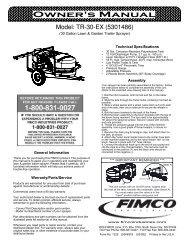
<strong>Owner's</strong> <strong>Manual</strong><br />
Model: ATVBK-710 (5301271)<br />
(7-Nozzle Deluxe Boom Assembly w/Brackets & Connecting Fittings)<br />
(Tank NOT Included with Boom Kit)<br />
Technical Specifications<br />
• 7-Nozzle Boom Assembly (Diaphragm/Check Valve Nozzles)<br />
• 140" Spray Coverage<br />
• Corrosion-Resistant Nozzles<br />
Assembly<br />
Remove the parts to the boom assembly from the carton. Refer<br />
to the parts list and exploded view drawing to help identify all the<br />
components.<br />
General Information<br />
Thank you for purchasing this product. The purpose of this<br />
manual is to assist you in operating and maintaining your boom<br />
kit. Please read it carefully, as it furnishes information which<br />
will help you achieve years of trouble-free operation.<br />
Warranty/Parts/Service<br />
For home usage, products are warranted for one year from date<br />
of purchase against manufacturer or workmanship defects.<br />
Commercial users have a 90 day warranty.<br />
1. Attach the tank to the brackets loosely as shown in the<br />
exploded view.<br />
2. Place the sprayer onto the carrier rack of the ATV. Use the u-<br />
bolts and hardware to secure the tank mount to the rack.<br />
3. Connect the boom mounting brackets to the tank mounting<br />
brackets with hardware provided as shown. Note these brackets<br />
will be located about 16 1/4" apart on most ATV's. Now tighten<br />
all bolts and nuts.<br />
4. Center the center section of the boom onto your boom<br />
mounts, and secure in place with the hardware provided. Be<br />
sure that the outer booms will fold 'backwards'. The boom should<br />
be about 17"-19" above the ground.<br />
5. Attach the nozzle harness assembly to the boom. The<br />
threaded part of the nozzles are to be inserted through the<br />
hoses, and secured with the brass hex nuts provided. The end<br />
boom members should fold towards the rear of the sprayer.<br />
Your authorized dealer is the best source of replacement parts<br />
and service. To obtain prompt, efficient service, always<br />
remember to give the following information...<br />
- Correct Part Description and/or part number.<br />
- Model number/Serial number of your sprayer.<br />
Part descriptions and part numbers can be obtained from the<br />
illustrated parts list section(s) of this manual.<br />
Whenever you need parts or repair service, contact your<br />
distributor/dealer first. For warranty work, always take your<br />
original sales slip, or other evidence of purchase date, to your<br />
distributor/dealer.<br />
www.fimcoindustries.com<br />
1000 <strong>FIMCO</strong> Lane, P.O. Box 1700, North Sioux City, SD 57049<br />
Toll Free Phone: 800-831-0027 : Toll Free Fax: 800-494-0440<br />
Form No. 754 [5004580 (03/13)] Printed in the U.S.A.
Speed in M.P.H.<br />
(Miles per Hour)<br />
1.0<br />
2.0<br />
3.0<br />
4.0<br />
5.0<br />
6.0<br />
7.0<br />
8.0<br />
9.0<br />
10.0<br />
(Assembly)<br />
6. Route your boom feeder hose from the manifold, to the<br />
back end of the sprayer. Join the hose to the tee barb,<br />
then clamp in place with a hose clamp.<br />
7. An additional set of plumbing fittings are included with<br />
your boom kit. These may or may not be used. Fig. A<br />
shows how these fittings will attach to your sprayer,<br />
providing your sprayer has the 12V pump mounted on the<br />
"top" of your tank. If your sprayer has the manifold<br />
assembly attached to the outlet side of the pump, as<br />
shown, you probably will need to utilize these fittings.<br />
For a top-mounted pump attachment to the tank, a 13/16"<br />
diameter hole must be drilled through the top of the tank<br />
for the grommet which has the bypass hose routed<br />
through it. After threading the fittings together, locate the<br />
place on your tank for the hole so that the hose can be<br />
inserted without causing kinks.<br />
CAUTION: Never use a metal object or other sharp<br />
item for cleaning a nozzle tip. It is better to use a<br />
nozzle brush (NOT wire brush) or compressed air for<br />
tip cleaning.<br />
Testing the Sprayer<br />
NOTE:<br />
It is VERY important for you to test your sprayer with<br />
plain water before actual spraying is attempted. This<br />
will enable you to check the sprayer for leaks, without<br />
the possibility of losing any expensive chemicals.<br />
Add water to the tank & drive to the starting place for<br />
spraying. When you are ready to spray, turn the boom<br />
valve to the "on" position. This will start solution spraying<br />
from the tips of the boom. The pressure will decrease<br />
slightly when the boom is spraying. Adjust the pressure by<br />
turning the "ON/OFF" valve lever on the bypass line valve.<br />
Read the operating instructions and Initially begin spraying<br />
by closing the 'bypass' valve (this is the center ON/OFF<br />
valve located at the center port of your manifold assembly)<br />
and opening the boom line valve (this is the 'other' valve on<br />
the manifold). This will enable the air in the line to be<br />
eliminated (purged) through all the tips, while building<br />
pressure. When everything tests all right (no leaks, & good<br />
pressure), add the desired chemicals to the mixture and<br />
water combination and start your spraying operation.<br />
Adjust the pressure and spray as you did in the testing<br />
procedure.<br />
Conditions of weather and terrain must be considered<br />
when setting the sprayer. Do not spray on windy days.<br />
Protective clothing must be worn in some cases.<br />
Be sure to read the chemical label(s) correctly!<br />
Time Required in seconds to travel a distance of:<br />
100 Ft.<br />
68 sec.<br />
34<br />
23<br />
17<br />
14<br />
11<br />
9.7<br />
8.5<br />
7.6<br />
Speed Chart<br />
200 Ft.<br />
136 sec.<br />
68<br />
45<br />
34<br />
27<br />
23<br />
19<br />
17<br />
15<br />
6.8 14<br />
300 Ft.<br />
205 sec.<br />
102<br />
68<br />
51<br />
41<br />
34<br />
29<br />
26<br />
23<br />
20<br />
Calibration<br />
Chemical labels may show application rates in gallons<br />
per acre, gallons per 1000 square feet, or gallons per 100<br />
square feet. You will note that the tip chart shows all 3 of<br />
these rating systems.<br />
Once you know how much you are going to spray, then<br />
determine (from the tip chart) the spraying pressure<br />
(PSI), and the spraying speed (MPH).<br />
Determining the proper speed of the pulling vehicle can<br />
be done by marking off 100, 200, & 300 feet. The speed<br />
chart indicates the number of seconds it takes to travel<br />
the distances. Set the throttle and with a running start,<br />
travel the distances. Adjust the throttle until you travel the<br />
distances in the number of seconds indicated by the<br />
speed chart. Once you have reached the throttle setting<br />
needed, mark the throttle location so you can stop and go<br />
again, returning to the same speed.<br />
Add water and proper amount of chemical to the tank and<br />
drive to the starting place for spraying.<br />
After Spraying<br />
After use, fill the sprayer tank part way with water. Start<br />
the sprayer, and allow the clear water to be pumped<br />
through the plumbing system and out through the spray<br />
nozzles.<br />
Refill the tank about half full with plain water and use<br />
<strong>FIMCO</strong> Tank Neutralizer and Cleaner, and repeat cleaning<br />
instructions above.<br />
Flush the entire sprayer with the neutralizing/cleaning<br />
agent, then flush out one more time with plain water.<br />
Follow the chemical manufacturer's disposal instructions of<br />
all wash or rinsing water.<br />
For the boom, (if applicable) remove the tips and screens<br />
from the nozzle assemblies. Wash these items out<br />
thoroughly. Blow the orifice clean and dry. If the orifice<br />
remains clogged, clean it with a fine bristle (NOT WIRE)<br />
brush, or with a toothpick. Do not damage the orifice.<br />
Water rinse and dry the tips before storing.<br />
WARNING: Some chemicals will damage the pump<br />
valves if allowed to soak untreated for a length of<br />
time! ALWAYS flush the pump as instructed after each<br />
use.<br />
Winter Storage<br />
Drain all water out of your sprayer, paying special attention<br />
to the pump, handgun, and valve(s). These items are<br />
especially prone to damage from chemicals and freezing<br />
weather.<br />
The sprayer should be winterized before storage by<br />
pumping a solution of RV antifreeze through the entire<br />
plumbing system. This antifreeze solution should remain in<br />
the plumbing system during the winter months. When<br />
spring time comes and you are preparing your sprayer for<br />
the spray season, rinse the entire plumbing system out,<br />
clearing the lines of the antifreeze solution. Proper care<br />
and maintenance will prolong the life of your sprayer.<br />
Page 2
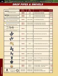
Exploded View/Parts List:<br />
ATVBK-710 (5301271)<br />
3<br />
13<br />
8<br />
3<br />
14<br />
10<br />
24<br />
11<br />
12<br />
2 7<br />
2<br />
26<br />
9<br />
9<br />
see page 4 for the<br />
Boom Assembly Parts Callout<br />
15<br />
25.8<br />
15<br />
5<br />
25.6<br />
23<br />
25.9<br />
21<br />
(Existing) Pump<br />
25.7<br />
20<br />
17<br />
19<br />
25.3 25.5<br />
1<br />
25.2<br />
4<br />
25.4<br />
25.1<br />
With your pump mounted on the 'side' of your tank,<br />
this will be your plumbing configuration/setup.<br />
Item<br />
No<br />
Part<br />
Number<br />
Qty<br />
Description<br />
1 5006209 2 Poly Knurled Swivel Nut, 3/4" FGHT<br />
2 5006259 6 3/8"-16 Hex Whiz (Flange) Locknut<br />
3 5006307 8 5/16"-18 Hex Whiz (Flange) Locknut<br />
4 5016066 2 Garden Hose Washer<br />
5 5020122 1 Hose, 1/2"-1 Brd. x 48"<br />
6 5020490 1 Hose, 3/8"-1 Brd. x 7 1/4"<br />
7 5034065 2 Round U-Bolt, 5/16"-18 x 1 1/2" x 2 3/16"<br />
8 5034220 2 Round U-Bolt, 5/16"-18 x 1 5/16" x 1 3/4"<br />
9 5034482 4 Carriage Bolt, 3/8"-16 x 1"<br />
10 5034524 2 Carriage Bolt, 3/8"-16 x 1 1/4"<br />
11 5034531 4 5/16"-18 x 5/8" Flange Lock Screw<br />
12 5038665 2 Boom Mounting Bracket<br />
13 5038667 1 Tank Mounting Plate (L.H.) (ATV)<br />
14 5038725 1 Tank Mounting Plate (R.H.) (ATV)<br />
15 5051114 2 Hose Clamp (3/8"-1/2")<br />
16 5051144 1 Hose Clamp (3/8")<br />
17 5075018 1 Grommet<br />
18 5075022 1 Grommet (5/8" I.D.)<br />
19 5100359 1 Poly Bypass "J" Hose (3.8/2.1 - 25 Gal.)<br />
20 5117314 1 #10-24 x 3" Truss Head Machine Screw<br />
21 5127192 1 Manifold Spacer (3.8gpm)<br />
22 5149034 1 Poly Swivel, 3/8" Hose Barb<br />
23 5167031 1 Gauge, Liquid-Filled, 0-100 PSI<br />
24 5274770 1 Deluxe Boom Assembly<br />
25 5275516 1 Manifold Assembly<br />
25.1 5010430 1 Port Kit Elbow, 1/2" FNPT<br />
25.2 5143405 1 Manifold w/Mounting Tab<br />
25.3 5143188 2 Nylon Shut-Off Valve (3/4" GHT)<br />
25.4 5016066 2 Garden Hose Washer<br />
25.5 5149034 1 Poly Swivel, 3/8" Hose Barb<br />
25.6 5149035 1 Poly Swivel, 1/2" Hose Barb<br />
25.7 5006209 2 Poly Knurled Swivel Nut, 3/4" FGHT<br />
25.8 5010236 1 Poly Elbow, 1/2" FNPT x 1/2" FNPT<br />
25.9 5041073 1 Poly Reducing Bushing, 1/2" MNPT x 1/4" FNPT<br />
26 5277765 1 7-Nozzle Harness Assembly (QJD Nozzles)<br />
Page 3
1.9<br />
LH Elbow<br />
1.6<br />
1.11<br />
1.12<br />
1.4<br />
1.1<br />
1.10<br />
1.10 1.2 Typ. 4xs<br />
Deluxe Boom Assembly<br />
2.1<br />
2.5.2<br />
2.5.3<br />
2.5.6<br />
2.5.1<br />
2.5.4<br />
2.5.5<br />
TEE<br />
2.6.1<br />
2.6.4<br />
2.6.5<br />
2.1<br />
2.6.2<br />
2.6.3<br />
2.6.6<br />
1.11<br />
1.3<br />
2.2<br />
2.7.1<br />
2.7.4<br />
2.7.5<br />
1.12<br />
2.4<br />
2.7.2 2.2<br />
2.7.3<br />
2.7.6<br />
1.11<br />
1.8<br />
1.5<br />
2.1<br />
1.2<br />
1.12<br />
1.3<br />
1.4<br />
1.11<br />
1.12<br />
1.11<br />
2.1<br />
2.1<br />
1.7<br />
RH Elbow<br />
1.9<br />
DETAIL LH Elbow<br />
DETAIL TEE<br />
DETAIL RH Elbow<br />
Item<br />
No<br />
Part Number Qty Description<br />
1 5274770 1 Deluxe Boom Assembly<br />
1.1<br />
1.2<br />
5006092<br />
5006259<br />
4<br />
5<br />
3/8"-16 Hex Locknut<br />
3/8"-16 Hex Whiz (Flange) Locknut<br />
1.3 5006345 4 3/8"-16 Flange Locknut (Grade F)<br />
1.4 5019228 2 Extension Spring<br />
1.5 5274518 1 Center Boom Weldment<br />
1.6 5274519 1 Outer Boom Weldment (L.H.)<br />
1.7 5274520 1 Outer Boom Weldment (R.H.)<br />
1.8 5038651 1 Boom Holder Bracket<br />
1.9 5003526 2 Rubber Edge Trim<br />
1.10<br />
1.11<br />
5016030<br />
5034482<br />
8<br />
5<br />
Flatwasher, 3/8"<br />
Carriage Bolt, 3/8"-16 x 1"<br />
1.12 5034524 4 Carriage Bolt, 3/8"-16 x 1 1/4"<br />
2 5277765 1 7-Nozzle Harness Assembly (QJ Noz.)<br />
2.1 5020416 5 Hose, 1/2"-1 Brd. x 19 3/8"<br />
2.2 5020144 2 Hose, 1/2"-1 Brd. x 10"<br />
2.3 5051114 14 Hose Clamp (3/8"-1/2")<br />
2.4 5086026 1 Poly Hose Tee, 1/2" HB<br />
2.5 5277714 1 (LH) Single Deluxe Nozzle Assembly<br />
Item<br />
No<br />
Part Number Qty Description<br />
2.5.1 5002489 1 Quick TeeJet Nozzle, 1/2" Single - Left<br />
2.5.2<br />
2.5.3<br />
5006087<br />
5016157<br />
1<br />
1<br />
Locknut, Brass<br />
Seat Washer (QJ Caps)<br />
2.5.4<br />
2.5.5<br />
5116019<br />
5046219<br />
1<br />
1<br />
Nozzle Strainer, Red (50 Mesh)<br />
Quick TeeJet Cap ONLY (Yellow)<br />
2.5.6 AIXR11002VP 1 Air-Induction XR Flat Spray Tip<br />
2.6 5277716 5 Double Deluxe Nozzle Assembly<br />
2.6.1 5002491 1 Quick TeeJet Nozzle, 1/2" Double<br />
2.6.2 5006087 1 Locknut, Brass<br />
2.6.3 5016157 1 Seat Washer (QJ Caps)<br />
2.6.4<br />
2.6.5<br />
5116019<br />
5046219<br />
1<br />
1<br />
Nozzle Strainer, Red (50 Mesh)<br />
Quick TeeJet Cap ONLY (Yellow)<br />
2.6.6 AIXR11002VP 1 Air-Induction XR Flat Spray Tip<br />
2.7 5277715 1 (RH) Single Deluxe Nozzle Assembly<br />
2.7.1 5002490 1 Quick TeeJet Nozzle, 1/2" Single - Right<br />
2.7.2<br />
2.7.3<br />
5006087<br />
5016157<br />
1<br />
1<br />
Locknut, Brass<br />
Seat Washer (QJ Caps)<br />
2.7.4<br />
2.7.5<br />
5116019<br />
5046219<br />
1<br />
1<br />
Nozzle Strainer, Red (50 Mesh)<br />
Quick TeeJet Cap ONLY (Yellow)<br />
2.7.6 AIXR11002VP 1 Air-Induction XR Flat Spray Tip<br />
Figure A<br />
Tip<br />
Number<br />
AIXR11002VP<br />
Tip<br />
Number<br />
AIXR11002VP<br />
Spray Tip Rate Chart<br />
Gallons Per Acre - Based on Water<br />
Spray PressureCapacity<br />
Height (psi) (GPM) 1 2 3 4<br />
MPH MPH MPH MPH MPH<br />
5<br />
MPH<br />
6 8<br />
MPH<br />
15<br />
18"<br />
30<br />
20<br />
0.12 35.6 17.8 11.8 8.9 7.1 5.9 4.5<br />
0.14 41.6 20.8 13.8 10.4 8.3 6.9 5.2<br />
0.17 50.4 25.2 16.8 12.6 10.1 8.4 6.3<br />
40 0.20 59.6 29.8 19.8 14.9 11.9 9.9 7.4<br />
Gallons Per 1000 Sq. Ft. - Based on Water<br />
Spray PressureCapacity<br />
Height (psi) (GPM) 2 3 4 5<br />
MPH MPH MPH MPH<br />
15 0.12 .41 .27 .20 .16<br />
18"<br />
30<br />
0.14<br />
0.17<br />
.48<br />
.58<br />
.32<br />
.39<br />
.24<br />
.29<br />
.19<br />
.23<br />
40 0.20 .68 .45 .34 .27<br />
Manifold Assembly<br />
A 13/16" dia. hole will need<br />
to be drilled through your<br />
tank, approximately here, for<br />
the grommet/bypass hose<br />
4<br />
22<br />
1<br />
16<br />
This grommet is to<br />
be placed through<br />
the hole you drill<br />
through your tank.<br />
6<br />
18<br />
With your pump mounted on the 'top' of your tank,<br />
this is how your bypass line will be configured.<br />
Page 4
Misc. Information<br />
Typical Spray Pattern<br />
(7-Nozzle Boom)<br />
110°<br />
Deluxe Boom Diaphragm Nozzle Attachment to Boom Member<br />
5006087<br />
Boom Member<br />
Diaphragm Nozzle Assembly<br />
Nozzle Assembly Installed onto Boom<br />
Spacer<br />
Manifold<br />
Screw<br />
Manifold Spacer Attachment<br />
NOTE:<br />
To install the manifold spacer, remove one screw holding the pump to<br />
the tank (upper left location as you're looking at the pump) and place<br />
the spacer between the manifold and the pump's foot. Replace original<br />
screw with the long machine screw, feeding it through the slot in the<br />
manifold and through the spacer, thus securing the manifold. This screw<br />
will be 2-1/2" long for the 2.1gpm pump, and 3" long for the 3.8gpm pump.<br />
This does not apply to units that use a 1.0 gpm pump.<br />
Page 5