Baseload LNG Production in Stavanger - Linde Engineering
Baseload LNG Production in Stavanger - Linde Engineering
Baseload LNG Production in Stavanger - Linde Engineering

Create successful ePaper yourself
Turn your PDF publications into a flip-book with our unique Google optimized e-Paper software.
14<br />
With the <strong>Stavanger</strong> project, for the first time a<br />
sta<strong>in</strong>less steel MCHE for <strong>LNG</strong> liquefaction service<br />
was put <strong>in</strong>to operation. Based on historical and<br />
market reasons, alum<strong>in</strong>ium was the state of the<br />
art material for the application of a CWHE <strong>in</strong><br />
natural gas bus<strong>in</strong>ess.<br />
Even though alum<strong>in</strong>ium is the state of the art<br />
material, sta<strong>in</strong>less steel can provide some benefits.<br />
Among those benefits are factors such as<br />
higher design pressures and temperatures, higher<br />
material strength values and less or no tube<br />
leakage. Especially for off-shore and mar<strong>in</strong>e<br />
service sta<strong>in</strong>less steel is by far better <strong>in</strong> fatigue<br />
resistance. As per L<strong>in</strong>de´s experience it is not<br />
recommendable to use alum<strong>in</strong>ium <strong>in</strong> any part<br />
of a heat exchanger for such applications.<br />
Further, the transition jo<strong>in</strong>ts from alum<strong>in</strong>ium to<br />
steel pip<strong>in</strong>g becomes obsolete. External loads<br />
imposed from structural attachments such as<br />
platforms or pipe racks can be accommodated<br />
easily. Inspections on the heat exchanger and<br />
ma<strong>in</strong>tenance on the surround<strong>in</strong>g <strong>in</strong>stallation can<br />
be executed by local staff without special alum<strong>in</strong>ium<br />
know-how.<br />
The <strong>Stavanger</strong> CWHE is fully made of sta<strong>in</strong>less<br />
steel, <strong>in</strong>clud<strong>in</strong>g all its <strong>in</strong>ternals. With a total<br />
weight of 120 metric tons and a heat<strong>in</strong>g area<br />
of about the size of a football field and tubes as<br />
long as the distance from Berl<strong>in</strong> to Copenhagen<br />
the MCHE ranges <strong>in</strong> the medium scale of world<br />
class MCHEs <strong>in</strong> <strong>LNG</strong> bus<strong>in</strong>ess. However, due to its<br />
unique material selection it can be considered as<br />
one of a k<strong>in</strong>d.<br />
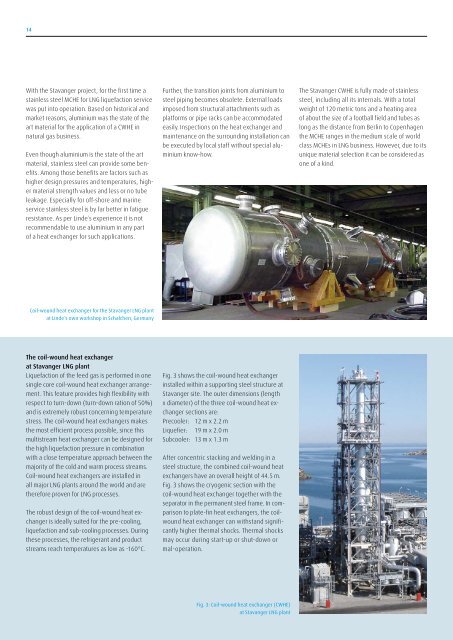
Coil-wound heat exchanger for the <strong>Stavanger</strong> <strong>LNG</strong> plant<br />
at L<strong>in</strong>de´s own workshop <strong>in</strong> Schalchen, Germany<br />
The coil-wound heat exchanger<br />
at <strong>Stavanger</strong> <strong>LNG</strong> plant<br />
Liquefaction of the feed gas is performed <strong>in</strong> one<br />
s<strong>in</strong>gle core coil-wound heat exchanger arrangement.<br />
This feature provides high flexibility with<br />
respect to turn-down (turn-down ration of 50%)<br />
and is extremely robust concern<strong>in</strong>g temperature<br />
stress. The coil-wound heat exchangers makes<br />
the most efficient process possible, s<strong>in</strong>ce this<br />
multistream heat exchanger can be designed for<br />
the high liquefaction pressure <strong>in</strong> comb<strong>in</strong>ation<br />
with a close temperature approach between the<br />
majority of the cold and warm process streams.<br />
Coil-wound heat exchangers are <strong>in</strong>stalled <strong>in</strong><br />
all major <strong>LNG</strong> plants around the world and are<br />
therefore proven for <strong>LNG</strong> processes.<br />
The robust design of the coil-wound heat exchanger<br />
is ideally suited for the pre-cool<strong>in</strong>g,<br />
liquefaction and sub-cool<strong>in</strong>g processes. Dur<strong>in</strong>g<br />
these processes, the refrigerant and product<br />
streams reach temperatures as low as -160°C.<br />
Fig. 3 shows the coil-wound heat exchanger<br />
<strong>in</strong>stalled with<strong>in</strong> a support<strong>in</strong>g steel structure at<br />
<strong>Stavanger</strong> site. The outer dimensions (length<br />
x diameter) of the three coil-wound heat exchanger<br />
sections are:<br />
Precooler: 12 m x 2.2 m<br />
Liquefier: 19 m x 2.0 m<br />
Subcooler: 13 m x 1.3 m<br />
After concentric stack<strong>in</strong>g and weld<strong>in</strong>g <strong>in</strong> a<br />
steel structure, the comb<strong>in</strong>ed coil-wound heat<br />
exchangers have an overall height of 44.5 m.<br />
Fig. 3 shows the cryogenic section with the<br />
coil-wound heat exchanger together with the<br />
separator <strong>in</strong> the permanent steel frame. In comparison<br />
to plate-f<strong>in</strong> heat exchangers, the coilwound<br />
heat exchanger can withstand significantly<br />
higher thermal shocks. Thermal shocks<br />
may occur dur<strong>in</strong>g start-up or shut-down or<br />
mal-operation.<br />
Fig. 3: Coil-wound heat exchanger (CWHE)<br />
at <strong>Stavanger</strong> <strong>LNG</strong> plant