Baseload LNG Production in Stavanger - Linde Engineering
Baseload LNG Production in Stavanger - Linde Engineering
Baseload LNG Production in Stavanger - Linde Engineering

You also want an ePaper? Increase the reach of your titles
YUMPU automatically turns print PDFs into web optimized ePapers that Google loves.
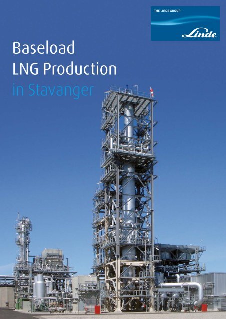
<strong>Baseload</strong><br />
<strong>LNG</strong> <strong>Production</strong><br />
<strong>in</strong> <strong>Stavanger</strong>
2<br />
Contents.<br />
3 Introduction<br />
4 Small to mid-scale <strong>LNG</strong> plants to monetize natural gas<br />
4 Small to mid-scale <strong>LNG</strong> plants versus world-scale <strong>LNG</strong> plants<br />
Safety and standards<br />
Plot space, location and <strong>in</strong>frastructure<br />
Modularization<br />
Project execution schedule for mid-scale <strong>LNG</strong> plants<br />
6 The basics<br />
8 Design features with respect<br />
to safety, emission and noise requirements<br />
10 Plant features<br />
Overall process<br />
Natural gas treatment<br />
Natural gas liquefaction<br />
<strong>LNG</strong> storage and load<strong>in</strong>g system<br />
Coil-wound heat exchanger<br />
17 Project execution<br />
18 L<strong>in</strong>de along the <strong>LNG</strong> value cha<strong>in</strong><br />
<strong>LNG</strong> receiv<strong>in</strong>g term<strong>in</strong>al <strong>in</strong> Nynäshamn, Sweden<br />
Ship unload<strong>in</strong>g station (jetty)<br />
<strong>LNG</strong> storage tank<br />
Trailer load<strong>in</strong>g station<br />
<strong>Production</strong> process<br />
23 Clos<strong>in</strong>g remarks<br />
24 Contact
3<br />
Introduction.<br />
As a lead<strong>in</strong>g eng<strong>in</strong>eer<strong>in</strong>g and <strong>in</strong>dustrial gases company, L<strong>in</strong>de<br />
are ideally positioned to capitalise on the dynamic natural gas<br />
market <strong>in</strong> several ways. As an eng<strong>in</strong>eer<strong>in</strong>g company, we design<br />
and build natural gas process<strong>in</strong>g and liquefaction plants. And as<br />
a gases company, we can distribute and market the product and<br />
– if so desired by the customer – also operate the plant.<br />
One of our most recent references for <strong>LNG</strong> baseload<br />
production with an annual capacity of<br />
300,000 tons of <strong>LNG</strong> is a plant built at the<br />
Norwegian wast cost near the city of Starvanger,<br />
started-up for commercial production <strong>in</strong> 2010.<br />
Thanks to L<strong>in</strong>de’s proprietary, most energyefficient<br />
liquefaction process, this new plant is<br />
cutt<strong>in</strong>g emission levels significantly compared<br />
with similar plants of this scale.<br />
The plant owner Skangass is a jo<strong>in</strong>t venture<br />
between the energy company LYSE Gass AS and<br />
the f<strong>in</strong>ancial <strong>in</strong>vestor Celsius Invest. Through its<br />
market<strong>in</strong>g company Nordic <strong>LNG</strong> AS, it will ma<strong>in</strong>ly<br />
target the Scand<strong>in</strong>avian and Baltic markets.<br />
Its customers will <strong>in</strong>clude the L<strong>in</strong>de subsidiary<br />
AGA Gas AB. Under the terms of the agreement<br />
between L<strong>in</strong>de´s Gases Division and Skangass,<br />
AGA will buy a significant amount of <strong>LNG</strong> from<br />
the new plant yearly and market it itself.<br />
With a <strong>LNG</strong> production capacity of 900 TPD or 0.3 MTPA the plant<br />
represents a new category of <strong>LNG</strong> plant types. This category<br />
of Small to Mid-Scale <strong>LNG</strong> plants shows the same reliability,<br />
robustness and safety features as world-scale <strong>LNG</strong> plants, while<br />
<strong>in</strong>tegration <strong>in</strong> exist<strong>in</strong>g sites is much less complex with moderate<br />
CAPEX and shorter project execution time.<br />
The plant is operated <strong>in</strong> base load mode and employs<br />
<strong>in</strong>termediate storage of the <strong>LNG</strong> product<br />
<strong>in</strong> an <strong>in</strong>sulated tank before it is loaded to road<br />
tankers or <strong>LNG</strong> carrier ships. The trucks carry the<br />
<strong>LNG</strong> over long distances to satellite stations <strong>in</strong><br />
various cities of Norway. After revaporization<br />
of the <strong>LNG</strong> the natural gas is f<strong>in</strong>ally distributed<br />
to a variety of <strong>in</strong>dustrial and private consumers.<br />
Another part of the <strong>LNG</strong> is transported by<br />
<strong>LNG</strong> carrier ship to the Nynäshamn <strong>LNG</strong> receiv<strong>in</strong>g<br />
term<strong>in</strong>al <strong>in</strong> Sweden. There it is regasified <strong>in</strong><br />
submerged combustion vaporizers and directly<br />
routed to a nearby ref<strong>in</strong>ery. A smaller quantity of<br />
the <strong>LNG</strong> received <strong>in</strong> this term<strong>in</strong>al is loaded <strong>in</strong>to<br />
road trucks for transport to remote locations <strong>in</strong><br />
Sweden.<br />
As <strong>LNG</strong> is considered the most environmentally<br />
friendly hydrocarbon fuel, it is expected that this<br />
domestic natural gas <strong>in</strong>itiative creates new gas<br />
markets and provides a great improvement<br />
to the energy supply situation <strong>in</strong> Sweden. This<br />
paper describes the <strong>Stavanger</strong> <strong>LNG</strong> facilities<br />
from gas treatment, liquefaction with a s<strong>in</strong>gle<br />
mixed refrigerant cycle <strong>in</strong> a coil-wound heat<br />
exchanger, through storage, to unload<strong>in</strong>g and<br />
distribution of the <strong>LNG</strong> to various consumers <strong>in</strong><br />
Norway and Sweden.
4<br />
Small to mid-scale <strong>LNG</strong> plants<br />
to monetize natural gas.<br />
Today, about 80 large <strong>LNG</strong> tra<strong>in</strong>s worldwide produce<br />
<strong>LNG</strong> for the world market. Plants currently<br />
under construction typically have tra<strong>in</strong> sizes <strong>in</strong><br />
excess of 4.0 million tons of <strong>LNG</strong> per year (worldscale<br />
<strong>LNG</strong>). The latest world-scale <strong>LNG</strong> tra<strong>in</strong>s<br />
have <strong>LNG</strong> production capacities of 7.8 million<br />
tons <strong>LNG</strong> per year cont<strong>in</strong>u<strong>in</strong>g the <strong>in</strong>dustry’s<br />
trend towards ever bigger tra<strong>in</strong>s.<br />
At the same time, the number of reservoirs support<strong>in</strong>g<br />
such large tra<strong>in</strong>s is limited. Additionally,<br />
such reservoirs may be difficult to access for various<br />
reasons such as remoteness, geological or<br />
political obstacles. Access<strong>in</strong>g those reservoirs<br />
requires more resources, capabilities and balance<br />
sheet strength than ever before.<br />
The above mentioned circumstances have prompted<br />
some market players to evaluate mid-scale <strong>LNG</strong><br />
technologies and opportunities, which means a<br />
tra<strong>in</strong> capacity between approx. 300.000 and<br />
1.000.000 tons of <strong>LNG</strong> per year. The <strong>Stavanger</strong><br />
<strong>LNG</strong> plant with an annual capacity of 300,000<br />
tons of <strong>LNG</strong> utilizes a L<strong>in</strong>de patented s<strong>in</strong>gle<br />
mixed refrigerant processes, which is considered<br />
the most appropriate process technology for a<br />
base load <strong>LNG</strong> service of this size. Other processes<br />
available, such as s<strong>in</strong>gle or double nitrogen<br />
expander processes, would require up to 80%<br />
more power and towards the upper end of the<br />
above-mentioned range have significant higher<br />
equipment count and have therefore not been<br />
considered for the <strong>Stavanger</strong> <strong>LNG</strong> plant project.<br />
Small to mid-scale <strong>LNG</strong> plants versus<br />
world-scale <strong>LNG</strong> plants.<br />
Safety and standards<br />
Mid-size <strong>LNG</strong> technology does not compromise<br />
on safety, reliability, robustness and efficiency.<br />
Applied processes and equipment are well-proven<br />
<strong>in</strong> base load service, comply with API standards<br />
and generally accepted safety philosophies<br />
and are derived from world-scale <strong>LNG</strong> projects.<br />
However, based on standard <strong>in</strong>dustry risk acceptance<br />
criteria, necessary safety distances <strong>in</strong>side<br />
of mid-scale <strong>LNG</strong> plants are significantly lower<br />
than those of world-scale <strong>LNG</strong> plants. A comparison<br />
between an executed 0.3 and 4.3 million tpa<br />
<strong>LNG</strong> plant <strong>in</strong>clud<strong>in</strong>g respective calculations of<br />
risk contours result <strong>in</strong> safety distances from the<br />
centre of the process plant to the nearest possible<br />
location of the plant fence of about 250 m<br />
and 750 m for a world-scale <strong>LNG</strong> plant respectively.<br />
One ma<strong>in</strong> reason for the differences is the<br />
significantly <strong>in</strong>creased amount of hydrocarbon<br />
<strong>in</strong>ventory <strong>in</strong> world-scale <strong>LNG</strong> plants as a result<br />
of the <strong>in</strong>creased mixed refrigerant cycle <strong>in</strong>ventory<br />
and larger tank sizes.<br />
Increased hydrocarbon <strong>in</strong>ventory raises the potential<br />
fire and explosion loads which, <strong>in</strong> turn,<br />
tighten the requirements regard<strong>in</strong>g the so called<br />
design accidental loads (DAL) for the plant equipment<br />
and bulk material. This either leads to <strong>in</strong>creased<br />
<strong>in</strong>vestment cost for re<strong>in</strong>forcement of the<br />
equipment or to <strong>in</strong>creased plot space requirements<br />
to br<strong>in</strong>g down the degree of congestion.<br />
Plot space, location and <strong>in</strong>frastructure<br />
Plot space requirements of mid-scale <strong>LNG</strong> plants<br />
differ significantly from world-scale <strong>LNG</strong> plants.<br />
A mid-scale <strong>LNG</strong> plant <strong>in</strong>clud<strong>in</strong>g build<strong>in</strong>gs, flare,<br />
<strong>LNG</strong> tank and utilities requires a plot space <strong>in</strong> the<br />
magnitude of 50.000 m 2 , while world-scale <strong>LNG</strong><br />
plants require <strong>in</strong> excess of ten times more plot<br />
space. Generally spoken world-scale <strong>LNG</strong> plants<br />
do not benefit from economies of scale regard<strong>in</strong>g<br />
plot space, but may even require proportionally<br />
larger plot spaces than expected based on<br />
the sheer scale <strong>in</strong> capacity and equipment. There<br />
are several reasons for this tendency.<br />
Firstly, a world-scale <strong>LNG</strong> plant <strong>in</strong> most cases<br />
requires a dedicated power generation system.<br />
Although the ma<strong>in</strong> refrigerant cycle compressors<br />
are often mechanically driven by gas turb<strong>in</strong>es,<br />
the large amount of smaller size mach<strong>in</strong>ery<br />
which is driven by electrical motors constitutes<br />
such high demand on electrical power that it<br />
cannot be supported from exist<strong>in</strong>g electrical <strong>in</strong>frastructure.<br />
In contrast, mid-scale <strong>LNG</strong> plants<br />
are often connected to the electrical network<br />
and no dedicated power generation system is<br />
required, especially if the ma<strong>in</strong> refrigerant<br />
compressor is directly driven by a gas turb<strong>in</strong>e.<br />
Depend<strong>in</strong>g on the boundary conditions, mid-size<br />
<strong>LNG</strong> plants up to a capacity of 500.000 to<br />
700.000 tpa may use the electrical network to<br />
electrically drive the ma<strong>in</strong> refrigerant compressor.<br />
Furthermore, mid-scale <strong>LNG</strong> plants are often<br />
fed with pre-treated feed gas from exist<strong>in</strong>g pipel<strong>in</strong>es<br />
systems. As a consequence, all or most plot<br />
space requirements for pre-treatment facilities,<br />
as well as condensate stabilization and fractionation<br />
units are elim<strong>in</strong>ated. In such cases where<br />
small quantities of natural gas liquids are removed,<br />
for example to adjust the heat<strong>in</strong>g value<br />
or achieve a methane number of the produced<br />
<strong>LNG</strong>, removed hydrocarbons are preferably used<br />
as fuel for the turb<strong>in</strong>e or hot oil system and no<br />
condensate or LPG tanks are required.<br />
Construction of a mid-scale <strong>LNG</strong> plant also requires<br />
significantly less area for lay down and<br />
work camps. The sheer size of the work force <strong>in</strong><br />
a world-scale <strong>LNG</strong> project (typically exceed<strong>in</strong>g<br />
several thousand men <strong>in</strong> peak times) itself poses<br />
one of the major challenges, especially s<strong>in</strong>ce<br />
most world-scale <strong>LNG</strong> plants are located <strong>in</strong> remote<br />
areas. Most of the world-scale <strong>LNG</strong> projects<br />
are greenfield projects for which a complete <strong>in</strong>frastructure<br />
<strong>in</strong>cl. park<strong>in</strong>g, access streets, adm<strong>in</strong>istration<br />
build<strong>in</strong>gs and also all utilities <strong>in</strong>clud<strong>in</strong>g<br />
the power plant must be established. In mid-scale<br />
<strong>LNG</strong> projects, the requirements for lay down areas
5<br />
and work camps are moderate <strong>in</strong> comparison and<br />
<strong>in</strong> many cases a significant part of the work force<br />
recruits are from the region.In summary, plot area,<br />
work force and camp size as well as explosion<br />
loads and build<strong>in</strong>g heights are lower for<br />
mid-scale <strong>LNG</strong> plants. These factors, especially<br />
at the lower end of the capacity range, allow the<br />
<strong>LNG</strong> plant to be located <strong>in</strong> <strong>in</strong>dustrial zones and<br />
thereby also benefit from exist<strong>in</strong>g <strong>in</strong>frastructure.<br />
Some sites which are typically considered as a<br />
mid-scale <strong>LNG</strong> location such as ref<strong>in</strong>ery sites,<br />
iron ore, bauxite or conta<strong>in</strong>er term<strong>in</strong>als may<br />
even offer wharf and jetty <strong>in</strong>frastructure. All the<br />
above can reduce overall mid-scale <strong>LNG</strong> project<br />
costs significantly.<br />
Modularization<br />
Module sizes and weights are considerably smaller<br />
for mid-scale <strong>LNG</strong> plants where even the tallest<br />
modules would not exceed a footpr<strong>in</strong>t of<br />
20 m x 20 m and weights would not exceed<br />
1,000 metric tons. Such sizes and weights can<br />
be easily lifted without be<strong>in</strong>g limited to only a<br />
few available special cranes, as would be the<br />
case for bigger modules be<strong>in</strong>g applied for world<br />
-scale <strong>LNG</strong> plants. Furthermore, sites are more<br />
accessible with smaller modules and it is likely<br />
that modules can be hauled <strong>in</strong> without dedicated<br />
new port <strong>in</strong>vestment <strong>in</strong> the case of mid–scale<br />
<strong>LNG</strong> plant modules. Last, but not least, a larger<br />
pool of potential module yards is available around<br />
the world for moderately sized modules. Some<br />
of the more complex and heavier modules of<br />
world –scale <strong>LNG</strong> plant s can only be built by a<br />
handful of yards.<br />
Project execution schedule<br />
Prior to commencement of any significant plant<br />
eng<strong>in</strong>eer<strong>in</strong>g activities, item s such as exploration<br />
on a world-scale <strong>LNG</strong> plant, appraisal and environmental<br />
approval activities as well as the development<br />
of field <strong>in</strong>frastructure may take many<br />
years. Plant eng<strong>in</strong>eer<strong>in</strong>g activities prior to a f<strong>in</strong>al<br />
<strong>in</strong>vestment decision (FID) <strong>in</strong> world-scale <strong>LNG</strong>, <strong>in</strong><br />
most cases, <strong>in</strong>volve a pre-FEED and a FEED study.<br />
The latter already <strong>in</strong>cludes a significant level of<br />
detail eng<strong>in</strong>eer<strong>in</strong>g activities, <strong>in</strong>clud<strong>in</strong>g a 30%<br />
plant model as a basis for a reasonably precise<br />
cost estimate. This need for detailed eng<strong>in</strong>eer<strong>in</strong>g<br />
is to a large extent driven by the sheer size<br />
and complexity of world-scale <strong>LNG</strong> projects. It<br />
typically takes two years to complete pre-FEED<br />
and FEED activities prior to any f<strong>in</strong>al <strong>in</strong>vestment<br />
decision.<br />
Mid-scale <strong>LNG</strong> projects, compared to world-scale<br />
<strong>LNG</strong> projects, are fast track projects. Secur<strong>in</strong>g<br />
off-take rights from exist<strong>in</strong>g natural gas pipel<strong>in</strong>e<br />
systems prior to start<strong>in</strong>g serious plant eng<strong>in</strong>eer<strong>in</strong>g<br />
activities takes comparatively little time.<br />
Mid-scale <strong>LNG</strong> projects <strong>in</strong> most cases can be tendered<br />
without upfront pre-FEED and FEED.<br />
Based on a high-quality basis of design there are<br />
contractors available to quote a firm price for eng<strong>in</strong>eer<strong>in</strong>g,<br />
procurement and erection (EPC) of a<br />
mid-scale <strong>LNG</strong> plant. All <strong>in</strong> all it may take around<br />
fifteen months to properly prepare for f<strong>in</strong>al <strong>in</strong>vestment<br />
decision from commencement of plant<br />
eng<strong>in</strong>eer<strong>in</strong>g activities. Construction activities of<br />
mid-scale <strong>LNG</strong> projects will take <strong>in</strong> the order of<br />
one and a half years less than construction activities<br />
of world-scale <strong>LNG</strong> projects. Mid-scale <strong>LNG</strong><br />
projects from commencement of first plant eng<strong>in</strong>eer<strong>in</strong>g<br />
activities can be expected to produce first<br />
<strong>LNG</strong> at l east two years earlier than a world-scale<br />
<strong>LNG</strong> plant. Tak<strong>in</strong>g <strong>in</strong>to account the entire project<br />
development phase mid-scale <strong>LNG</strong> projects, <strong>in</strong><br />
many cases, will produce first <strong>LNG</strong> four to five<br />
years earlier than world-scale <strong>LNG</strong> projects.<br />
Small to mid-scale <strong>LNG</strong> plants do not compromise<br />
on safety, reliability, robustness and efficiency<br />
<strong>in</strong> comparison to world-scale <strong>LNG</strong> facilities, while<br />
execution risks and time as well as capital requirements<br />
are significantly lower.
6<br />
The Basics.<br />
Basic data process design<br />
The design of the plant is based on state-ofthe-art<br />
natural gas liquefaction technology.<br />
Design basis<br />
The <strong>Stavanger</strong> <strong>LNG</strong> plant consists of natural gas<br />
treatment, gas liquefaction, <strong>LNG</strong> tank and load<strong>in</strong>g<br />
facilities as well as utilities. The liquefaction<br />
process is based on a most efficient s<strong>in</strong>gle mixed<br />
refrigerant cycle.<br />
The <strong>LNG</strong> production capacity of the plant is 900<br />
tpd with an expected on-stream time of 330 days<br />
per year. Design hourly liquefaction capacity is<br />
37 t/h with a storage capacity of 30,000 m³ of<br />
<strong>LNG</strong>, which is the equivalent of approx. 12 days<br />
production. The capacity of the <strong>LNG</strong> send-out<br />
and distribution system meets the requirement<br />
of load<strong>in</strong>g 25 - 100 m³/h by truck and 150 -<br />
1.000 m³/h by ship (dependent on ship size).<br />
Feed gas composition<br />
Composition (mole %):<br />
– Nitrogen 0.65<br />
– Methane 88.22<br />
– Ethane 8.43<br />
– Propane 0.55<br />
– Butanes 0.05<br />
– Pentanes 0.00<br />
In addition, CO 2 as well as traces of H 2 S and<br />
sulfur are present <strong>in</strong> the feed gas. The feed<br />
gas operat<strong>in</strong>g pressure is 120 bar g.<br />
<strong>LNG</strong> specification<br />
Composition (mole %):<br />
– Nitrogen max 1.0<br />
Ambient site conditions<br />
The average ambient temperature ranges from<br />
30°C <strong>in</strong> the warmest to -15°C <strong>in</strong> the coldest month.<br />
The design temperature for air-cool<strong>in</strong>g is 13.2°C.<br />
Utilities<br />
Instrument air, nitrogen and dem<strong>in</strong>eralized water<br />
are produced with<strong>in</strong> the <strong>LNG</strong> plant. Electric power,<br />
potable water and fire water are supplied from<br />
outside Battery Limit.<br />
The tank return gas as well as vapour return from<br />
<strong>LNG</strong> load<strong>in</strong>g is utilized as fuel gas. The fuel gas is<br />
used for flare pilots and fired heater of the hot<br />
oil unit. Not used fuel gas is sent as tail gas to the<br />
local gas grid at Battery Limit.<br />
The hot oil system provides the process heat for<br />
the plant at two temperature levels. Two cycles<br />
are <strong>in</strong>troduced, a medium temperature cycle for<br />
regeneration of the am<strong>in</strong>e and a high temperature<br />
cycle for heat<strong>in</strong>g of regeneration gas for the<br />
driers.<br />
Process features<br />
The ma<strong>in</strong> process and utility units are illustrated<br />
<strong>in</strong> the block diagram <strong>in</strong> Fig 1. The mixed refrigerant<br />
cycle liquefaction process requires the components<br />
nitrogen, ethylene, propane, butane,<br />
and a portion of the compressed tank return gas<br />
(L<strong>in</strong>de patent). Refrigerant nitrogen and purge<br />
nitrogen are identical and both generated <strong>in</strong> a<br />
nitrogen package.<br />
The liquefaction process is based on a<br />
most efficient s<strong>in</strong>gle mixed refrigerant<br />
cycle, which conta<strong>in</strong>s the components
7<br />
Sour gas<br />
Tail gas<br />
Fuel gas<br />
Refrigeration<br />
system<br />
Tank return gas<br />
(fuel gas)<br />
compression<br />
Purified<br />
feed gas<br />
Dry<br />
feed gas<br />
Vap. refr.<br />
Liqu. refr.<br />
<strong>LNG</strong><br />
Feed gas<br />
Let down station/<br />
feed meter<strong>in</strong>g<br />
station<br />
CO2<br />
removal<br />
Drier<br />
station<br />
NG<br />
liquefaction<br />
<strong>LNG</strong><br />
storage<br />
<strong>LNG</strong> ship<br />
load<strong>in</strong>g station<br />
(jetty)<br />
Waste water<br />
<strong>LNG</strong> truck<br />
load<strong>in</strong>g station<br />
(load<strong>in</strong>g bay)<br />
Waste water<br />
Fig1: Block diagram of the <strong>Stavanger</strong> <strong>LNG</strong> plant<br />
nitrogen, ethylene, propane, butane and<br />
a portion of the compressed tank return gas<br />
(L<strong>in</strong>de patent). This process has a superb<br />
efficiency and is easy to operate.
8<br />
Design features with respect<br />
to safety, emission and noise requirements.<br />
High material requirements<br />
The feed gas pressure at battery limit is 180 bar<br />
(209 barg design pressure), which allows very<br />
efficient natural gas liquefaction, but on the<br />
other hand poses very high demands on equipment<br />
and material selection.<br />
Low emission requirement<br />
The diagram shows the challeng<strong>in</strong>g low emission<br />
requirements which had to be followed for<br />
the <strong>Stavanger</strong> <strong>LNG</strong> plant project due to the str<strong>in</strong>gent<br />
permitt<strong>in</strong>g standard regime <strong>in</strong> Norway.<br />
Special care has to be taken on tightness and<br />
safe operation. Usually small/mid-scale <strong>LNG</strong><br />
plants use plate-f<strong>in</strong> heat exchangers for liquefaction.<br />
For the <strong>Stavanger</strong> coil-wound heat exchanger,<br />
L<strong>in</strong>de Eng<strong>in</strong>eer<strong>in</strong>g selected sta<strong>in</strong>less<br />
steel as material, due to the follow<strong>in</strong>g features:<br />
– Allowable stress is a factor 2 to alum<strong>in</strong>um<br />
– Elongation at fracture is 5 times higher<br />
– Extremely robust and flexible <strong>in</strong> operation<br />
High permitt<strong>in</strong>g standard regime <strong>in</strong> Norway<br />
All electric drive<br />
Smokeless flare<br />
High efficient process<br />
and equipment<br />
is sav<strong>in</strong>g energy<br />
LOW EMISSIONS<br />
Feed gas dur<strong>in</strong>g<br />
start-up routed to gas<br />
grid <strong>in</strong>tead of flar<strong>in</strong>g<br />
No cont<strong>in</strong>uous am<strong>in</strong>e<br />
purge from the CO 2<br />
wash unit<br />
Tank and ship return<br />
gas is sent to a low<br />
pressure gas grid<br />
Autothermal H 2 S<br />
conversion without<br />
additional fuel gas
9<br />
Ferry term<strong>in</strong>al ~200 m<br />
Industrial park ~500 m<br />
Residential area ~1.000 m<br />
<strong>Stavanger</strong> <strong>LNG</strong> plant site location<br />
Noise requirements<br />
Due to the nearby settlement the <strong>Stavanger</strong> <strong>LNG</strong><br />
plant must fulfill the challeng<strong>in</strong>g noise requirement<br />
of 53 db at battery limit. In order to fulfill<br />
this str<strong>in</strong>gent requirement the follow<strong>in</strong>g features<br />
were applied:<br />
– Low noise fans and air-coolers<br />
– Air-coolers partly housed-<strong>in</strong><br />
– Cycle compressor <strong>in</strong>side a noise hood<br />
– Majority of pip<strong>in</strong>g and equipment is sound<br />
<strong>in</strong>sulated<br />
– Control Valves are low noise trims<br />
– High demand to noise reduction at all<br />
equipment<br />
High standard permitt<strong>in</strong>g regime <strong>in</strong> Norway<br />
Beside the high standard permitt<strong>in</strong>g regime <strong>in</strong><br />
Norway the <strong>Stavanger</strong> <strong>LNG</strong> project was fac<strong>in</strong>g<br />
further challenges through the follow<strong>in</strong>g facts:<br />
– Located on old ref<strong>in</strong>ery site with<strong>in</strong> <strong>in</strong>dustrial<br />
zone<br />
– Limited available plot space of 68 m x 47 m<br />
– Challeng<strong>in</strong>g environment with nearby traffic,<br />
<strong>in</strong>dustrial and residential build<strong>in</strong>gs<br />
– Numerous residence reservations / objections<br />
managed and overcome by L<strong>in</strong>de and the client
10<br />
Plant features.<br />
Overall process<br />
The plant consists of natural gas treatment and<br />
liquefaction, <strong>LNG</strong> storage tank, one <strong>LNG</strong> ship<br />
load<strong>in</strong>g and one truck fill<strong>in</strong>g station. The natural<br />
gas is cooled, liquefied and subcooled <strong>in</strong> a coilwound<br />
heat exchanger by a most efficient s<strong>in</strong>gle<br />
mixed refrigerant cycle. This cycle provides cold<br />
temperatures by Joule-Thomson expansion and<br />
liquid vaporization of the mixed refrigerant with<strong>in</strong><br />
the shell of the CWHE. The refrigerant cycle is<br />
recompressed <strong>in</strong> an electric motor driven <strong>in</strong>tegrally<br />
geared turbo compressor.<br />
Natural gas liquefaction<br />
After CO 2 and H 2 O removal, the natural gas is<br />
routed to the cold part of the process, which<br />
features three coil-wound heat exchanger bundles<br />
<strong>in</strong>tegrated <strong>in</strong> one shell (“rocket”), as well<br />
as several separation vessels. The natural gas<br />
is first cooled <strong>in</strong> the feed gas precooler. The<br />
purified gas is condensed <strong>in</strong> a feed gas liquefier<br />
and subcooled <strong>in</strong> a feed gas subcooler (fig. 2).<br />
Natural gas treatment<br />
Natural gas is received from Karstø natural gas<br />
process<strong>in</strong>g plant with a pressure of 120 bara and<br />
a temperature of 10°C. The feed gas is routed to<br />
the am<strong>in</strong>e wash unit (L<strong>in</strong>de design) for removal<br />
of CO 2 . The sweet feed gas leav<strong>in</strong>g the CO 2 wash<br />
column is routed to the drier station. The aMDEA<br />
CO 2 wash unit is a L<strong>in</strong>de designed unit customized<br />
to the high feed gas pressure of 110 bar.<br />
Fig 2: L<strong>in</strong>de patented natural gas liquefaction process LIMUM ®<br />
<strong>LNG</strong><br />
Advanced s<strong>in</strong>gle flow<br />
MR1<br />
NG
11<br />
<strong>LNG</strong> truck load<strong>in</strong>g station with 30,000 m³ <strong>LNG</strong> storage tank<br />
at <strong>Stavanger</strong> <strong>LNG</strong> plant<br />
Refrigerant system<br />
The refrigerant gas stream is withdrawn from the<br />
shell side of the precool<strong>in</strong>g section of the cryogenic<br />
coil-wound heat exchanger. The refrigerant<br />
is slightly super-heated. It passes the cycle<br />
compressor suction drum and is compressed <strong>in</strong><br />
the first stage of the refrigerant cycle compressor.<br />
It is cooled aga<strong>in</strong>st air <strong>in</strong> the <strong>in</strong>ter- and aftercooler<br />
result<strong>in</strong>g <strong>in</strong> partial condensation. The<br />
result<strong>in</strong>g liquid is separated <strong>in</strong> the cycle compressor<br />
<strong>in</strong>termediate discharge drums.<br />
The liquid from the medium pressure discharge<br />
drum is routed to the cryogenic heat exchanger,<br />
where it is subcooled and used for the precool<strong>in</strong>g<br />
of the natural gas after expansion <strong>in</strong> a Joule-<br />
Thomson valve.<br />
The cycle gas from the high pressure drum is<br />
cooled to the same temperature, partly condensed<br />
and fed to the cold refrigerant separator.<br />
The liquid from this separator is subcooled <strong>in</strong> the<br />
cryogenic heat exchanger to a low temperature<br />
so that it can be used efficiently as a refrigerant<br />
after expansion <strong>in</strong> a Joule-Thomson valve.<br />
The vapor from the cold refrigerant separator is<br />
condensed and subcooled <strong>in</strong> the cryogenic heat<br />
exchanger to a sufficiently low temperature. This<br />
process step provides the f<strong>in</strong>al cold for the natural<br />
gas subcool<strong>in</strong>g after throttl<strong>in</strong>g <strong>in</strong> a Joule-<br />
Thomson valve. After expansion to the lower<br />
pressure, the cycle gas streams are warmed up<br />
and vaporized <strong>in</strong> the common shell side of the<br />
cryogenic heat exchangers and returned jo<strong>in</strong>tly<br />
to the suction side of the first stage of the refrigerant<br />
cycle compressor.<br />
<strong>LNG</strong> storage and load<strong>in</strong>g system<br />
Ma<strong>in</strong> purpose of the <strong>LNG</strong> storage and load<strong>in</strong>g<br />
unit is the <strong>in</strong>termediate storage of <strong>LNG</strong> prior to<br />
load<strong>in</strong>g <strong>in</strong>to <strong>LNG</strong> carriers at the jetty and/or to<br />
<strong>LNG</strong> trucks at the truck load<strong>in</strong>g bay. The 30.000 m 3<br />
<strong>LNG</strong> storage is designed as full conta<strong>in</strong>ment tank<br />
for <strong>LNG</strong> storage at atmospheric pressure. <strong>LNG</strong><br />
vapor generated dur<strong>in</strong>g zero ship load<strong>in</strong>g, max.<br />
ship load<strong>in</strong>g, zero truck load<strong>in</strong>g and max. truck<br />
load<strong>in</strong>g are routed via the <strong>LNG</strong> storage tank to<br />
the tank return gas compressors. Excess vapors,<br />
dur<strong>in</strong>g load<strong>in</strong>g of ships with <strong>in</strong>creased tank temperatures<br />
at start of <strong>LNG</strong> load<strong>in</strong>g are sent to the<br />
flare system.<br />
Approx. 90% of the <strong>LNG</strong> production is exported<br />
by ship and 10% is exported by truck at the truck<br />
load<strong>in</strong>g bay. The tank is filled cont<strong>in</strong>uously dur<strong>in</strong>g<br />
operation of the liquefaction system at a fill<strong>in</strong>g<br />
rate of 83 m 3 /h respectively 37.500 kg/h.
12<br />
<strong>LNG</strong> ship load<strong>in</strong>g facility of the<br />
<strong>Stavanger</strong> <strong>LNG</strong> plant<br />
<strong>LNG</strong> ship load<strong>in</strong>g<br />
For <strong>LNG</strong> ship load<strong>in</strong>g the <strong>LNG</strong> is pumped to the<br />
<strong>LNG</strong> carriers by means of one of 2 x 100 % ship<br />
load<strong>in</strong>g pumps, which are <strong>in</strong>stalled <strong>in</strong>side the<br />
<strong>LNG</strong> tank. The <strong>LNG</strong> from the <strong>LNG</strong> ship load<strong>in</strong>g<br />
pumps is routed via the <strong>LNG</strong> ship load<strong>in</strong>g l<strong>in</strong>e<br />
and the load<strong>in</strong>g hoses to the manifold of the <strong>LNG</strong><br />
carrier at the jetty. The send out rates of the <strong>LNG</strong><br />
ship load<strong>in</strong>g pump can be up to 1.000 m 3 /h<br />
depend<strong>in</strong>g on the size of the <strong>LNG</strong> carrier. The<br />
flow rates are controlled by the variable speed<br />
of the electric motor.<br />
Dur<strong>in</strong>g no ship load<strong>in</strong>g operation, the <strong>LNG</strong> ship<br />
load<strong>in</strong>g l<strong>in</strong>e is kept cold by cont<strong>in</strong>uously circulat<strong>in</strong>g<br />
<strong>LNG</strong> by means of one <strong>LNG</strong> truck load<strong>in</strong>g pump<br />
via a recirculation l<strong>in</strong>e and <strong>LNG</strong> load<strong>in</strong>g l<strong>in</strong>e back<br />
to the <strong>LNG</strong> storage tank. This is done to keep the<br />
load<strong>in</strong>g system cold and gas free at all times, to<br />
allow immediate start up of ship load<strong>in</strong>g after<br />
arrival of a <strong>LNG</strong> carrier.<br />
<strong>LNG</strong> truck load<strong>in</strong>g<br />
Dur<strong>in</strong>g <strong>LNG</strong> truck load<strong>in</strong>g the <strong>LNG</strong> is pumped<br />
to the <strong>LNG</strong> truck by means of the <strong>LNG</strong> truck<br />
load<strong>in</strong>g pumps, which are <strong>in</strong>stalled <strong>in</strong> the <strong>LNG</strong><br />
tank.<br />
The <strong>LNG</strong> from the <strong>LNG</strong> truck load<strong>in</strong>g pumps is<br />
routed via the <strong>LNG</strong> truck load<strong>in</strong>g l<strong>in</strong>e and load<strong>in</strong>g<br />
hose to the <strong>LNG</strong> truck at the <strong>LNG</strong> truck load<strong>in</strong>g<br />
bay. Dur<strong>in</strong>g load<strong>in</strong>g of <strong>LNG</strong> trucks the normal rate<br />
per pump is 65 m³/h. Both <strong>LNG</strong> truck load<strong>in</strong>g<br />
pumps can be used simultaneously. The truck<br />
load<strong>in</strong>g bay is designed to load 10 <strong>LNG</strong> trucks<br />
with a capacity of 50-58 m 3 with<strong>in</strong> 12 hours<br />
(daylight) around the year. This is equivalent to<br />
the export of 10 % of the <strong>LNG</strong> net production<br />
rate via the <strong>LNG</strong> trucks. Truck loads are metered<br />
by a weigh bridge.<br />
Fuel system<br />
The net flash/boil-off and displacement gas<br />
from the <strong>LNG</strong> storage tank is compressed <strong>in</strong> the<br />
tank return gas compressor to 12 bar a. Part of<br />
the tank return gas is routed to the fired hot oil<br />
heater as fuel gas. About 2000 m³/h are sent<br />
to the local grid as sales gas. For start-up, feed<br />
gas may also be used as fuel gas. It is expanded<br />
to fuel gas pressure and warmed up by the<br />
start-up fuel gas heater.<br />
Hot oil unit<br />
The hot oil system provides the process heat for<br />
the plant at two temperature levels. Two cycles<br />
are <strong>in</strong>troduced, a medium temperature cycle for<br />
regeneration of the am<strong>in</strong>e and a high temperature<br />
cycle for the heat<strong>in</strong>g of the regeneration<br />
gas for the driers. The heat for both cycles is<br />
provided by a hot oil heater, which is fired with<br />
fuel gas. The hot oil is heated to 260°C to supply<br />
heat for the regeneration gas heat<strong>in</strong>g. To<br />
allow for start-up dur<strong>in</strong>g w<strong>in</strong>ter conditions, the<br />
system is heat traced.
13<br />
Coil-wound heat exchanger.<br />
A special feature of the cryogenic section of<br />
the plant is the coil-wound heat exchanger<br />
designed and built by L<strong>in</strong>de.<br />
The coil-wound heat exchanger (CWHE) can be<br />
considered as the heart of the <strong>LNG</strong> plant. Its purpose<br />
is to liquefy the dried and cleaned natural<br />
gas (NG). This is realized by pre-cool<strong>in</strong>g, liquefy<strong>in</strong>g<br />
and sub-cool<strong>in</strong>g natural gas <strong>in</strong> a three stage<br />
heat exchanger. The L<strong>in</strong>de proprietary coil-wound<br />
heat exchanger technology perfectly fulfils the<br />
requirements for such equipment.<br />
With its history go<strong>in</strong>g back as far as to the time<br />
when Carl von L<strong>in</strong>de for the first time successfully<br />
liquefied air on an <strong>in</strong>dustrial scale, L<strong>in</strong>de is<br />
now look<strong>in</strong>g back on more than thousand coilwound<br />
heat exchangers successfully manufactured<br />
and brought to operation. CWHE’s are<br />
robust, compact and reliable and serve a wide<br />
field of applications with a large range of temperature,<br />
pressure and can be designed and<br />
fabricated <strong>in</strong> various materials. They are suitable<br />
for s<strong>in</strong>gle as well as two phase streams and can<br />
accommodate several process streams <strong>in</strong> one<br />
exchanger. Each CWHE is specifically tailor made<br />
for the thermal & hydraulic performance requirements.<br />
Heat<strong>in</strong>g surfaces up to 40,000 square<br />
metres can be <strong>in</strong>stalled <strong>in</strong> heat exchangers bundles<br />
with diameters up to 5.5 metres and a total<br />
weight of 250 tons <strong>in</strong> the L<strong>in</strong>de own fabrication<br />
facility. Larger units are feasible and are assembled<br />
<strong>in</strong> yards close to the coast.<br />
In general a CWHE comprises multiple layers of<br />
tubes particularly selected for the anticipated<br />
service, which are wound helically around a centre<br />
pipe. For the reason of perfect tightness, the<br />
bundle tubes are welded to the tube sheet and<br />
for highest process efficiency the bundle is covered<br />
by an additional <strong>in</strong>ner shell, the so called<br />
shroud. A highly developed distribution system<br />
above the bundle makes sure that for fall<strong>in</strong>g film<br />
evaporation, the <strong>in</strong>stalled heat<strong>in</strong>g surface is<br />
used most efficiently. The proprietary suspension<br />
system allows the L<strong>in</strong>de CWHE to cope with<br />
large temperature differences and changes as<br />
well as sharp pressure drops dur<strong>in</strong>g operation.<br />
In particular dur<strong>in</strong>g start-ups, shut downs and<br />
operational upset conditions L<strong>in</strong>de CWHE are<br />
well known as a very robust equipment without<br />
any k<strong>in</strong>d of bundle sagg<strong>in</strong>g. Temperature elements<br />
as well as laser-optic measurement devices<br />
<strong>in</strong>stalled dur<strong>in</strong>g bundle w<strong>in</strong>d<strong>in</strong>g provide<br />
the relevant data for optimum process control.<br />
After assembly with the pre-fabricated pressure<br />
vessel shell, the complete CWHE is not only<br />
subject to pressure test<strong>in</strong>g, but also extensive<br />
tightness test<strong>in</strong>g with pure helium to ensure<br />
highest quality. L<strong>in</strong>de coil-wound heat exchangers<br />
are 100% self-dra<strong>in</strong><strong>in</strong>g which reduces possible<br />
corrosion defects, accumulation of process<br />
impurities and defrost time.<br />
<strong>Stavanger</strong> coil-wound heat exchanger ready for delivery<br />
at L<strong>in</strong>de´s own workshop <strong>in</strong> Schalchen, Germany
14<br />
With the <strong>Stavanger</strong> project, for the first time a<br />
sta<strong>in</strong>less steel MCHE for <strong>LNG</strong> liquefaction service<br />
was put <strong>in</strong>to operation. Based on historical and<br />
market reasons, alum<strong>in</strong>ium was the state of the<br />
art material for the application of a CWHE <strong>in</strong><br />
natural gas bus<strong>in</strong>ess.<br />
Even though alum<strong>in</strong>ium is the state of the art<br />
material, sta<strong>in</strong>less steel can provide some benefits.<br />
Among those benefits are factors such as<br />
higher design pressures and temperatures, higher<br />
material strength values and less or no tube<br />
leakage. Especially for off-shore and mar<strong>in</strong>e<br />
service sta<strong>in</strong>less steel is by far better <strong>in</strong> fatigue<br />
resistance. As per L<strong>in</strong>de´s experience it is not<br />
recommendable to use alum<strong>in</strong>ium <strong>in</strong> any part<br />
of a heat exchanger for such applications.<br />
Further, the transition jo<strong>in</strong>ts from alum<strong>in</strong>ium to<br />
steel pip<strong>in</strong>g becomes obsolete. External loads<br />
imposed from structural attachments such as<br />
platforms or pipe racks can be accommodated<br />
easily. Inspections on the heat exchanger and<br />
ma<strong>in</strong>tenance on the surround<strong>in</strong>g <strong>in</strong>stallation can<br />
be executed by local staff without special alum<strong>in</strong>ium<br />
know-how.<br />
The <strong>Stavanger</strong> CWHE is fully made of sta<strong>in</strong>less<br />
steel, <strong>in</strong>clud<strong>in</strong>g all its <strong>in</strong>ternals. With a total<br />
weight of 120 metric tons and a heat<strong>in</strong>g area<br />
of about the size of a football field and tubes as<br />
long as the distance from Berl<strong>in</strong> to Copenhagen<br />
the MCHE ranges <strong>in</strong> the medium scale of world<br />
class MCHEs <strong>in</strong> <strong>LNG</strong> bus<strong>in</strong>ess. However, due to its<br />
unique material selection it can be considered as<br />
one of a k<strong>in</strong>d.<br />
Coil-wound heat exchanger for the <strong>Stavanger</strong> <strong>LNG</strong> plant<br />
at L<strong>in</strong>de´s own workshop <strong>in</strong> Schalchen, Germany<br />
The coil-wound heat exchanger<br />
at <strong>Stavanger</strong> <strong>LNG</strong> plant<br />
Liquefaction of the feed gas is performed <strong>in</strong> one<br />
s<strong>in</strong>gle core coil-wound heat exchanger arrangement.<br />
This feature provides high flexibility with<br />
respect to turn-down (turn-down ration of 50%)<br />
and is extremely robust concern<strong>in</strong>g temperature<br />
stress. The coil-wound heat exchangers makes<br />
the most efficient process possible, s<strong>in</strong>ce this<br />
multistream heat exchanger can be designed for<br />
the high liquefaction pressure <strong>in</strong> comb<strong>in</strong>ation<br />
with a close temperature approach between the<br />
majority of the cold and warm process streams.<br />
Coil-wound heat exchangers are <strong>in</strong>stalled <strong>in</strong><br />
all major <strong>LNG</strong> plants around the world and are<br />
therefore proven for <strong>LNG</strong> processes.<br />
The robust design of the coil-wound heat exchanger<br />
is ideally suited for the pre-cool<strong>in</strong>g,<br />
liquefaction and sub-cool<strong>in</strong>g processes. Dur<strong>in</strong>g<br />
these processes, the refrigerant and product<br />
streams reach temperatures as low as -160°C.<br />
Fig. 3 shows the coil-wound heat exchanger<br />
<strong>in</strong>stalled with<strong>in</strong> a support<strong>in</strong>g steel structure at<br />
<strong>Stavanger</strong> site. The outer dimensions (length<br />
x diameter) of the three coil-wound heat exchanger<br />
sections are:<br />
Precooler: 12 m x 2.2 m<br />
Liquefier: 19 m x 2.0 m<br />
Subcooler: 13 m x 1.3 m<br />
After concentric stack<strong>in</strong>g and weld<strong>in</strong>g <strong>in</strong> a<br />
steel structure, the comb<strong>in</strong>ed coil-wound heat<br />
exchangers have an overall height of 44.5 m.<br />
Fig. 3 shows the cryogenic section with the<br />
coil-wound heat exchanger together with the<br />
separator <strong>in</strong> the permanent steel frame. In comparison<br />
to plate-f<strong>in</strong> heat exchangers, the coilwound<br />
heat exchanger can withstand significantly<br />
higher thermal shocks. Thermal shocks<br />
may occur dur<strong>in</strong>g start-up or shut-down or<br />
mal-operation.<br />
Fig. 3: Coil-wound heat exchanger (CWHE)<br />
at <strong>Stavanger</strong> <strong>LNG</strong> plant
15<br />
Temperature measurement by optical fibers<br />
The load dependent temperature profile <strong>in</strong> coil- wound heat exchangers<br />
is a desired quantity to further ref<strong>in</strong>e and improve the design. With knowledge<br />
of the temperature profile, p<strong>in</strong>ch po<strong>in</strong>ts can be analyzed and optimized<br />
and energy consumption can be reduced. A fiber based l<strong>in</strong>ear temperature<br />
measurement system was built <strong>in</strong>to the coil-wound heat exchanger<br />
to measure this data. The fiber measurement system allows<br />
remote operational assistance with measurement data backup from<br />
L<strong>in</strong>de head office <strong>in</strong> Pullach/Germany.<br />
Temperature profile measured by optical fibers<br />
<strong>in</strong> liquefier section of coil-wound heat exchanger<br />
at <strong>Stavanger</strong> <strong>LNG</strong> plant<br />
Temperature is probably the quantity that is<br />
measured most <strong>in</strong> <strong>LNG</strong> plants. Thermocouples or<br />
thermistors are ma<strong>in</strong>ly applied to pip<strong>in</strong>g, vessels<br />
and mach<strong>in</strong>ery. When look<strong>in</strong>g at the ma<strong>in</strong> heat<br />
exchanger, special knowledge for <strong>in</strong>stallation of<br />
temperature measurements has been developed<br />
<strong>in</strong> the past. The aim was to ga<strong>in</strong> <strong>in</strong>sight <strong>in</strong>to<br />
temperature distribution and thus liquid distribution<br />
<strong>in</strong>side the bundles of the coil wound heat<br />
exchanger (CWHE). However, more detailed<br />
<strong>in</strong>formation is coupled to number of measurement<br />
po<strong>in</strong>ts and thus to <strong>in</strong>stallation effort.<br />
The <strong>Stavanger</strong> CWHE has been equipped with a<br />
new approach to measure temperature, which is<br />
based on optical fibers. The fiber optic distributed<br />
temperature sens<strong>in</strong>g (DTS) technique is an<br />
<strong>in</strong>novative way to obta<strong>in</strong> thousands of temperature<br />
measurements with comparatively low<br />
effort. A s<strong>in</strong>gle optical fiber can replace many<br />
po<strong>in</strong>t sensors because temperature is measured<br />
along the fiber with a local resolution of down to<br />
half a meter. By co-<strong>in</strong>stallation of the fiber with<br />
the tubes dur<strong>in</strong>g fabrication of the CWHE a huge<br />
amount of s<strong>in</strong>gle measurement po<strong>in</strong>ts is accessible<br />
from <strong>in</strong>side the bundle of the CWHE.
16<br />
Briefly, the measurement pr<strong>in</strong>ciple is based on<br />
the Raman-effect as a result of laser-light transmitted<br />
through the fiber and scatter<strong>in</strong>g of spectral<br />
components <strong>in</strong> backward direction. This<br />
components travel to the start<strong>in</strong>g po<strong>in</strong>t of the<br />
fiber where they are filtered and detected. The<br />
<strong>in</strong>tensities of these spectral components are<br />
related to the temperature at the orig<strong>in</strong> of this<br />
scatter<strong>in</strong>g process. Because the velocity of light<br />
propagation <strong>in</strong> the optical fiber is well known,<br />
the location can be determ<strong>in</strong>ed from the timeof-flight<br />
of the return<strong>in</strong>g backscattered light.<br />
The DTS system enables more than 4000 s<strong>in</strong>gle<br />
measurement po<strong>in</strong>ts from the bundles of the<br />
<strong>Stavanger</strong> CWHE, which is a huge number compared<br />
to the few s<strong>in</strong>gle po<strong>in</strong>t measurements<br />
used previously. Dur<strong>in</strong>g start-up of the <strong>LNG</strong><br />
plant, the system has already proven its usefulness<br />
and successfully demonstrated its capabilities<br />
even at the low temperatures of natural gas<br />
liquefaction.<br />
In the figure, the shell-side temperature distribution<br />
<strong>in</strong> the liquefier bundle dur<strong>in</strong>g cool-down<br />
is shown <strong>in</strong> form of a longitud<strong>in</strong>al section. S<strong>in</strong>ce<br />
full 3D temperature data is available, also cross<br />
sections or iso-surfaces of temperature can be<br />
generated to visualize radial or axial distribution,<br />
p<strong>in</strong>ch po<strong>in</strong>ts or other effects.<br />
This is truly a step change <strong>in</strong> process measurement.<br />
The wealth of <strong>in</strong>formation from this <strong>in</strong>novative<br />
measurement technique not only supports<br />
R&D and eng<strong>in</strong>eer<strong>in</strong>g for improvement of<br />
CWHEs but will also support our customers with<br />
valuable real-time data for optimiz<strong>in</strong>g energy<br />
efficiency or detect<strong>in</strong>g critical states, e.g. <strong>in</strong><br />
<strong>LNG</strong>-FPSO.<br />
Fibre optic temperature<br />
measurement <strong>in</strong> <strong>LNG</strong> heat exchangers<br />
In August 2009, the world’s first coil-wound heat<br />
exchanger made completely of sta<strong>in</strong>less steel<br />
for the liquefaction of natural gas (to be used <strong>in</strong><br />
<strong>Stavanger</strong>, Norway) was delivered on time to the<br />
customer. This heat exchanger employs new<br />
temperature measur<strong>in</strong>g technology us<strong>in</strong>g fibre<br />
optics (glass fibres).<br />
These are capable of measur<strong>in</strong>g temperatures<br />
throughout the entire CWHE, along both the<br />
length and diameter. The <strong>in</strong>formation is graphically<br />
displayed us<strong>in</strong>g special software. With this<br />
technology, it is possible to detect temperature<br />
changes and, <strong>in</strong>directly, the distribution of liquid<br />
cool<strong>in</strong>g agent at the edge of the CWHE. It is now<br />
possible, for the first time, to compare the theory<br />
with empirical data.<br />
The pr<strong>in</strong>ciple of measur<strong>in</strong>g temperatures us<strong>in</strong>g<br />
fibre optics has been known for some time and<br />
is based on the “Raman effect”. The monochromatic<br />
laser light that runs through the glass<br />
fibres is scattered on the SiO 2 lattice both elastically<br />
(i.e. with no change <strong>in</strong> colour) and also<br />
<strong>in</strong>elastically. The <strong>in</strong>elastic light scatter<strong>in</strong>g produces<br />
two signals which are respectively red<br />
and blue-shifted from the laser wavelength,<br />
referred to as Stokes and anti-Stokes l<strong>in</strong>es.<br />
However, the idea of us<strong>in</strong>g this pr<strong>in</strong>ciple <strong>in</strong> a<br />
coil-wound heat exchanger is new. The ma<strong>in</strong><br />
advantages over the previous system are expected<br />
to be the improved control options. The<br />
new system will also provide important <strong>in</strong>formation<br />
regard<strong>in</strong>g the efficiency and functionality<br />
of the cool<strong>in</strong>g agent distributor.<br />
The idea was implemented by <strong>in</strong>stall<strong>in</strong>g glass<br />
fibres with an overall length of approximately<br />
2,400 metres <strong>in</strong> the <strong>Stavanger</strong> heat exchanger.<br />
“The most difficult th<strong>in</strong>g was to avoid bend<strong>in</strong>g<br />
the glass fibres (d=0.2 mm) dur<strong>in</strong>g the manufactur<strong>in</strong>g<br />
of the heat exchanger and to avoid damag<strong>in</strong>g<br />
them dur<strong>in</strong>g the weld<strong>in</strong>g work which was<br />
carried out <strong>in</strong> the follow<strong>in</strong>g months. The outstand<strong>in</strong>g<br />
cooperation of everyone <strong>in</strong>volved, <strong>in</strong><br />
particular the care and quality awareness demonstrated<br />
by the L<strong>in</strong>de manufactur<strong>in</strong>g employees<br />
dur<strong>in</strong>g production, was the key to success of<br />
this project”, said Gerhard Dägl<strong>in</strong>g, the Project<br />
Leader responsible for <strong>in</strong>stall<strong>in</strong>g the optical<br />
fibres.<br />
Press release of the optical fibers<br />
measur<strong>in</strong>g pr<strong>in</strong>ciple
17<br />
<strong>Stavanger</strong> <strong>LNG</strong> plant<br />
Project execution.<br />
L<strong>in</strong>de Eng<strong>in</strong>eer<strong>in</strong>g successfully delivered to the<br />
client a fully operational base load <strong>LNG</strong> plant.<br />
The overall scope of work was to realize through<br />
all phases of project execution the implementation<br />
of a <strong>LNG</strong> production plant <strong>in</strong> Risavika near<br />
<strong>Stavanger</strong> <strong>in</strong> Norway, accord<strong>in</strong>g to Norwegian/<br />
European Standard NS EN 1473. The <strong>LNG</strong> plant<br />
was built on a 300 m x 100 m plot, which was<br />
partly reclaimed from sea. The scope of work<br />
consisted of the complete <strong>LNG</strong> plant started-up<br />
for commercial production with all tests passed<br />
successfully.<br />
The client provided the atmospheric <strong>LNG</strong> tank<br />
with a total capacity of 30,000 m³ and the <strong>LNG</strong><br />
jetty as an open berth structure with concrete<br />
beams and slabs and a load<strong>in</strong>g platform area of<br />
40 m x 20 m. L<strong>in</strong>de’s scope covered the whole<br />
process equipment for the <strong>LNG</strong> tank <strong>in</strong>clud<strong>in</strong>g<br />
the removable electric motor driven <strong>LNG</strong> Load<strong>in</strong>g<br />
Pumps and the mar<strong>in</strong>e load<strong>in</strong>g arm for the<br />
jetty with a capacity up to 10,000 m³/h (typical<br />
ship tank volume).<br />
The plant achieved the status “commission<strong>in</strong>g<br />
completed and <strong>in</strong> all respect ready for <strong>LNG</strong> production”<br />
<strong>in</strong> August 2010, 1 month ahead of<br />
schedule.<br />
This ahead of time completion was a result of<br />
the early def<strong>in</strong>ition of handover systems and<br />
pressure/electrical/<strong>in</strong>strumentation test packs<br />
dur<strong>in</strong>g the eng<strong>in</strong>eer<strong>in</strong>g phase, which allowed a<br />
prioritised pre-manufactur<strong>in</strong>g of pip<strong>in</strong>g, sequential<br />
pip<strong>in</strong>g <strong>in</strong>stallation and pressure test<strong>in</strong>g,<br />
followed by a staggered mechanical completion<br />
of subsystems .<br />
The construction phase was supported by the<br />
“<strong>in</strong>tegrated completion management system<br />
(ICM)”, a newly developed and for the <strong>Stavanger</strong><br />
project customized software package which allowed<br />
the detailed follow up and exact progress<br />
measur<strong>in</strong>g of all relevant construction activities.
18<br />
L<strong>in</strong>de along the <strong>LNG</strong> value cha<strong>in</strong>.<br />
Under the terms of the agreement between<br />
the L<strong>in</strong>de Gases Division and the owner of the<br />
<strong>Stavanger</strong> <strong>LNG</strong> plant Skangass, L<strong>in</strong>de Gases<br />
Division <strong>in</strong> Sweden (AGA) will buy a significant<br />
volume of <strong>LNG</strong> from the new plant each year.<br />
A part of the <strong>Stavanger</strong> <strong>LNG</strong> product is transported<br />
by vessel to the Nynäshamn <strong>LNG</strong> receiv<strong>in</strong>g<br />
term<strong>in</strong>al <strong>in</strong> Sweden. It is partly regasified <strong>in</strong><br />
submerged combustion vaporizers and routed<br />
to a nearby ref<strong>in</strong>ery. A smaller quantity of the<br />
<strong>LNG</strong> received <strong>in</strong> this term<strong>in</strong>al is loaded <strong>in</strong>to <strong>LNG</strong><br />
trucks for road transport to remote locations <strong>in</strong><br />
Sweden.<br />
<strong>LNG</strong> receiv<strong>in</strong>g term<strong>in</strong>al <strong>in</strong> Nynäshamn/<br />
Sweden<br />
L<strong>in</strong>de’s subsidiary, Cryo AB from Gothenburg,<br />
has built this mid-scale <strong>LNG</strong> term<strong>in</strong>al <strong>in</strong> Sweden<br />
with a 20,000 m 3 full conta<strong>in</strong>ment <strong>LNG</strong> storage<br />
tank, which is the first term<strong>in</strong>al <strong>in</strong> the country.<br />
L<strong>in</strong>de’s sister company AGA Sweden is the owner<br />
and operator of this term<strong>in</strong>al. AGA is engaged<br />
<strong>in</strong> the value cha<strong>in</strong> of small-scale <strong>LNG</strong>, by shipp<strong>in</strong>g<br />
it from the <strong>LNG</strong> plant at <strong>Stavanger</strong> to the<br />
term<strong>in</strong>al, before distribut<strong>in</strong>g it by truck to the<br />
end clients.<br />
CRYO AB has designed and manufactured more<br />
than 60 flat bottom tanks for cryogenic service,<br />
mostly for air gases, <strong>in</strong> Europe and South America.<br />
In addition, cryogenic equipment for natural<br />
gas has been delivered to a number of projects.<br />
Construction site of the <strong>LNG</strong> receiv<strong>in</strong>g term<strong>in</strong>al<br />
Nynäshamn , Sweden
19<br />
<strong>LNG</strong> receiv<strong>in</strong>g term<strong>in</strong>al ma<strong>in</strong> operations<br />
Fig. 4 shows a sketch of the <strong>LNG</strong> receiv<strong>in</strong>g term<strong>in</strong>al.<br />
Its purpose is to perform the follow<strong>in</strong>g tasks:<br />
– Receive, Liquefied Natural Gas<br />
from ships<br />
– <strong>LNG</strong> storage<br />
– Handle BOG (Boil Off Gas)<br />
– Supply pressurized and gasified NG (GNG)<br />
to Nynäs ref<strong>in</strong>ery<br />
– Discharge <strong>LNG</strong> to trailers<br />
Ship unload<strong>in</strong>g station (jetty)<br />
The term<strong>in</strong>al receives <strong>LNG</strong> from <strong>LNG</strong> carriers on a<br />
regularly basis. The <strong>LNG</strong> is unloaded by means of<br />
<strong>LNG</strong> pumps on board of the carrier. <strong>LNG</strong> is pumped<br />
to a load<strong>in</strong>g arm at the Jetty station and further<br />
to the <strong>LNG</strong> storage tank through an <strong>in</strong>sulated<br />
pipe. The normal load<strong>in</strong>g of the <strong>LNG</strong> ship load<strong>in</strong>g<br />
pump is 1000 m³/h. Only one of two pumps is <strong>in</strong><br />
operation, the other is <strong>in</strong> stand-by.<br />
From the <strong>LNG</strong> storage tank vapor is routed back<br />
to the carrier via another <strong>in</strong>sulated pipe and a<br />
separate load<strong>in</strong>g (gas return) arm. The vapor<br />
return l<strong>in</strong>e relieves displacement gas <strong>in</strong> the<br />
storage tank caused by the “piston effect” from<br />
the rais<strong>in</strong>g liquid level. The vapor is transferred<br />
to the carrier where it counteracts the (vacuum)<br />
“piston” effect from the s<strong>in</strong>k<strong>in</strong>g liquid level.<br />
<strong>LNG</strong> storage tank<br />
The <strong>LNG</strong> Storage Tank at the Term<strong>in</strong>al has a work<strong>in</strong>g<br />
capacity of 20,000 m 3 and is a “full conta<strong>in</strong>ment<br />
tank” with operat<strong>in</strong>g pressures slightly<br />
above atmospheric pressure. Two <strong>LNG</strong> pumps<br />
are submerged <strong>in</strong> the liquid. <strong>LNG</strong> is pumped<br />
either to the re-condenser, to <strong>LNG</strong> trailers and/<br />
or to the booster pumps for ref<strong>in</strong>ery gas supply.<br />
Internal pump recirculation and cont<strong>in</strong>uous cool<strong>in</strong>g<br />
of external pip<strong>in</strong>g are also important tasks<br />
for the <strong>LNG</strong> pumps.<br />
On top of the <strong>LNG</strong> storage capacity, the storage<br />
tank, by its vapor space, also accommodates a<br />
great gas buffer<strong>in</strong>g capacity. This gas buffer<strong>in</strong>g<br />
capacity is used to collect and even out pressure<br />
sw<strong>in</strong>gs <strong>in</strong> the entire “uncompressed” gas volume<br />
of the term<strong>in</strong>al. This <strong>in</strong>cludes discharge gas from<br />
safety, and thermal relief valves. All such gas<br />
sources are connected to the storage tank vapor<br />
space via a ma<strong>in</strong> blow-off l<strong>in</strong>e.<br />
Fig. 4: Process overview of the <strong>LNG</strong> receiv<strong>in</strong>g term<strong>in</strong>al<br />
<strong>in</strong> Nynäshamn/Sweden<br />
Steam<br />
Gas cooler<br />
Vaporizer<br />
Re-condenser<br />
GNG<br />
to Nynäshamn<br />
Buffer tank<br />
BOG compressor<br />
Booster<br />
pumps<br />
GNG<br />
to Nynäshamn<br />
Flare<br />
Gas return<br />
<strong>LNG</strong> to term<strong>in</strong>al<br />
<strong>LNG</strong> to trailers<br />
Trailer gas return<br />
<strong>LNG</strong> ship<br />
Storage<br />
tank<br />
Trailer
20<br />
Truck unload<strong>in</strong>g at <strong>LNG</strong> satellite station<br />
Trailer load<strong>in</strong>g station<br />
Dur<strong>in</strong>g load<strong>in</strong>g of <strong>LNG</strong> trucks the normal load<strong>in</strong>g<br />
rate per pump is 65 m³/h. Both <strong>LNG</strong> truck load<strong>in</strong>g<br />
pumps can be used simultaneously. The expected<br />
total time for fill<strong>in</strong>g a trailer is close to<br />
one hour, <strong>in</strong>clud<strong>in</strong>g time for connection and<br />
disconnection. The actual fill<strong>in</strong>g time is 45 m<strong>in</strong>.<br />
At simultaneous fill<strong>in</strong>g of two trailers, the total<br />
<strong>LNG</strong> flow rate is 150 m 3 /h. Thus, with the two<br />
fill<strong>in</strong>g stations operat<strong>in</strong>g <strong>in</strong> parallel, theoretically<br />
some fifty trailers could be filled every 24 hours.<br />
Boil-off gas system<br />
Two boil-off compressors, each with 100 % capacity,<br />
are <strong>in</strong>stalled at the term<strong>in</strong>al. The ma<strong>in</strong><br />
task is to evacuate excessive boil-off and displacement<br />
gases <strong>in</strong> order to keep the pressure<br />
<strong>in</strong> the storage tank with<strong>in</strong> acceptable limits.<br />
The compressed gases are diverted to the recondenser.<br />
Re-condenser and <strong>LNG</strong> buffer tank<br />
In order to enhance the flexibility of the term<strong>in</strong>al<br />
output, a recondenser with buffer tank is<br />
<strong>in</strong>stalled. The recondenser converts the compressed<br />
boil-off gas to <strong>LNG</strong>. The <strong>LNG</strong> is delivered<br />
to the ref<strong>in</strong>ery gas system or to trailers. The<br />
buffer tank <strong>in</strong>creases the amount of converted<br />
BOG s<strong>in</strong>ce <strong>LNG</strong> can be stored at occasions with<br />
low consumption, e.g. between trailer fill<strong>in</strong>g<br />
when the ref<strong>in</strong>ery is down.
21<br />
Ref<strong>in</strong>ery gas system<br />
The ref<strong>in</strong>ery gas system pressurizes and vaporizes<br />
<strong>LNG</strong>. The gas is delivered to the adjacent<br />
Nynäs ref<strong>in</strong>ery at the required pressure and<br />
temperature, also leav<strong>in</strong>g a control marg<strong>in</strong> to<br />
the ref<strong>in</strong>ery process. In order to maximize the<br />
BOG condensation, the <strong>LNG</strong> is taken from the<br />
buffer tank whenever <strong>LNG</strong> is available. If not,<br />
<strong>LNG</strong> is taken directly from the storage tank.<br />
Pressurization is done by means of booster<br />
pumps located under the buffer tank. Vaporization<br />
and heat<strong>in</strong>g to acceptable temperature is<br />
carried out by means of steam heated “water<br />
bath” vaporizers. From the vaporizers, the gasified<br />
natural gas (GNG) is routed further to the<br />
ref<strong>in</strong>ery.<br />
<strong>Production</strong> process<br />
In order to avoid operational <strong>in</strong>terruptions, systems<br />
and components are redundant as far as<br />
reasonable. Basically all critical equipment has<br />
2 x 100 % capacity. In some cases the 100 %<br />
load does however not <strong>in</strong>clude special, seldom<br />
occurr<strong>in</strong>g comb<strong>in</strong>ations of operation. There are<br />
also two trailer fill stations, however not primarily<br />
as a backup measure. Critical <strong>in</strong>struments<br />
have a “2/3” arrangement, mean<strong>in</strong>g that the<br />
<strong>in</strong>strument has three sensors and one of these<br />
may fail without caus<strong>in</strong>g an <strong>in</strong>strument failure.<br />
<strong>LNG</strong> ship load<strong>in</strong>g arm <strong>in</strong>stalled<br />
on the jetty of the <strong>Stavanger</strong> <strong>LNG</strong> plant
22<br />
Plant overall operational philosophy<br />
The term<strong>in</strong>al is designed for unmanned operation.<br />
Control and supervision may well be performed<br />
from a remote control room. Alarms will<br />
be transferred to operators on duty, directly via<br />
SMS or from the remote control room. All safety<br />
functions will be controlled by the PLC at the<br />
term<strong>in</strong>al. The functions <strong>in</strong> the remote control<br />
room will also be available at the local control<br />
room <strong>in</strong> the service build<strong>in</strong>g.<br />
The trailer fill<strong>in</strong>g process will be operated by the<br />
truck driver. The trailer fill<strong>in</strong>g procedure has<br />
automatic functions for fast and reliable service.<br />
At ship unload<strong>in</strong>g, the jetty has to be attended<br />
by at least two operators. The operator will be<br />
<strong>in</strong> contact with the ship and the remote control<br />
room dur<strong>in</strong>g the whole unload<strong>in</strong>g process. Before<br />
unload<strong>in</strong>g from the ship, the operator will<br />
have to <strong>in</strong>spect the equipment <strong>in</strong>volved <strong>in</strong> the<br />
operation l<strong>in</strong>es, valves and <strong>in</strong>struments.<br />
Environmental aspects have been considered<br />
when design<strong>in</strong>g the term<strong>in</strong>al <strong>in</strong>clud<strong>in</strong>g design<br />
of process control. Emissions of NG to the environment<br />
are almost totally elim<strong>in</strong>ated and emissions<br />
of combustion gases (flar<strong>in</strong>g) will only<br />
take place at rare occasions and only as a measure<br />
to avoid release of unburned combustible<br />
gas.<br />
Term<strong>in</strong>al layout and safety considerations<br />
The term<strong>in</strong>al will be divided <strong>in</strong>to four separate<br />
areas; jetty area, tank area, process area and<br />
tank fill<strong>in</strong>g area. This layout, based on the condition<br />
of the surround<strong>in</strong>gs, provides <strong>in</strong>creased<br />
security s<strong>in</strong>ce a potentially hazardous event <strong>in</strong><br />
one of the areas is not likely to affect the other<br />
areas.<br />
All steel structures, pip<strong>in</strong>g systems and other<br />
metal parts and equipment are connected to a<br />
common equipotent bound<strong>in</strong>g system. A zone<br />
classification will prevent the existence of ignition<br />
sources at the term<strong>in</strong>al.<br />
Additional precautions dur<strong>in</strong>g ship unload<strong>in</strong>g<br />
If any problems occur dur<strong>in</strong>g ship unload<strong>in</strong>g,<br />
pump<strong>in</strong>g will cease immediately and valves to<br />
isolate the transfer pipel<strong>in</strong>e will close <strong>in</strong> a predeterm<strong>in</strong>ed<br />
sequence. This sequence follows<br />
recommendations by SIGTTO, Society of International<br />
Gas Tanker and Term<strong>in</strong>al Operation. It is<br />
controlled by equipment on the tanker and on<br />
shore. The emergency shut down, ESD, procedure<br />
can be <strong>in</strong>itiated either from the ship or from<br />
the shore.<br />
<strong>LNG</strong> truck load<strong>in</strong>g station of the <strong>Stavanger</strong> <strong>LNG</strong> plant
23<br />
Clos<strong>in</strong>g remarks.<br />
Small and mid-scale <strong>LNG</strong> technology will enable<br />
<strong>in</strong>dustrial users, such as ref<strong>in</strong>eries and<br />
power plants, <strong>in</strong> stranded markets to switch to<br />
cost efficient and environmental friendly gas.<br />
The demand for natural gas <strong>in</strong> Norway and<br />
Sweden is projected to <strong>in</strong>crease <strong>in</strong> the near<br />
future. The <strong>Stavanger</strong> <strong>LNG</strong> plant <strong>in</strong> connection<br />
with the Nynäshamn <strong>LNG</strong> receiv<strong>in</strong>g term<strong>in</strong>al<br />
will open a new era <strong>in</strong> meet<strong>in</strong>g the <strong>in</strong>creas<strong>in</strong>g<br />
demand <strong>in</strong> this area.<br />
With the <strong>in</strong>troduction of such <strong>LNG</strong> plants, comb<strong>in</strong>ed<br />
with the respective transport and regasification<br />
<strong>in</strong>frastructure, natural gas markets can<br />
be dynamically developed. It is evident that natural<br />
gas, as a cleaner fuel, will play an <strong>in</strong>creas<strong>in</strong>gly<br />
important role <strong>in</strong> the primary energy mix.<br />
With the <strong>LNG</strong> from <strong>Stavanger</strong> plant, a high degree<br />
of flexibility <strong>in</strong> the energy supply will be<br />
made available to the benefit of all natural gas<br />
consumers with fluctuat<strong>in</strong>g or peak demand<br />
profiles.<br />
The <strong>Stavanger</strong> <strong>LNG</strong> plant provides a means to<br />
commercialize <strong>in</strong>digenous natural gas resources.<br />
This, <strong>in</strong> return, supports the local economy and<br />
provides additional labor.<br />
Furthermore the <strong>Stavanger</strong> <strong>LNG</strong> plant provides<br />
a “rubber tire pipel<strong>in</strong>e” to small natural gas consumers<br />
<strong>in</strong> Norway and Sweden. The transport of<br />
<strong>LNG</strong> via tanker trucks makes the distribution of<br />
natural gas to <strong>in</strong>termediate-sized consumers<br />
also possible.<br />
Mid-scale <strong>LNG</strong> plants are an economically <strong>in</strong>terest<strong>in</strong>g<br />
alternative to world-scale <strong>LNG</strong> plants.<br />
While export schemes appear to require plant<br />
capacities above 500.000 tpa, merchant <strong>LNG</strong><br />
schemes appear economically attractive already<br />
at smaller capacities. Mid-scale <strong>LNG</strong> plants, by<br />
virtue of their moderate size and complexity,<br />
have the potential to be located <strong>in</strong> <strong>in</strong>dustrialized<br />
areas which allows <strong>in</strong>vestment <strong>in</strong> <strong>in</strong>frastructure<br />
to be kept at reasonable levels. Capital requirements<br />
and execution risks are significantly lower<br />
than <strong>in</strong> world-scale <strong>LNG</strong> projects. Moderate size<br />
and complexity allows companies lack<strong>in</strong>g the<br />
resources of an <strong>in</strong>ternational oil & gas major to<br />
develop and even fully control an <strong>LNG</strong> project<br />
while enjoy<strong>in</strong>g an equal amount of off-take,<br />
level of safety, quality, reliability and a comparable<br />
efficiency as <strong>in</strong> a m<strong>in</strong>ority sharehold<strong>in</strong>g of a<br />
world-scale <strong>LNG</strong> project. Moreover, mid-scale<br />
<strong>LNG</strong> offers a unique opportunity to monetize<br />
local or regional gas surpluses of moderate size<br />
<strong>in</strong> a fast track fashion.<br />
Some of the target regions are not connected<br />
to major gas pipel<strong>in</strong>es, s<strong>in</strong>ce the <strong>in</strong>itial gas consumption<br />
rate would not justify such a large<br />
<strong>in</strong>vestment. Therefore, the <strong>LNG</strong> supply will <strong>in</strong>itiate<br />
the penetration of these regional markets<br />
with environmentally friendly fuel.<br />
With the <strong>in</strong>troduction of such small to midscale<br />
<strong>LNG</strong> plant types comb<strong>in</strong>ed with the<br />
respective transport <strong>in</strong>frastructure, natural<br />
gas markets can be dynamically <strong>in</strong>troduced<br />
and developed.
Design<strong>in</strong>g processes – construct<strong>in</strong>g plants.<br />
L<strong>in</strong>de´s Eng<strong>in</strong>eer<strong>in</strong>g Division cont<strong>in</strong>uously develops extensive process eng<strong>in</strong>eer<strong>in</strong>g know-how <strong>in</strong> the plann<strong>in</strong>g,<br />
project management and construction of turnkey <strong>in</strong>dustrial plants.<br />
The range of products comprises:<br />
− Petrochemical plants<br />
− <strong>LNG</strong> and natural gas process<strong>in</strong>g plants<br />
− Synthesis gas plants<br />
− Hydrogen plants<br />
− Gas process<strong>in</strong>g plants<br />
− Adsorption plants<br />
− Air separation plants<br />
− Cryogenic plants<br />
− Biotechnological plants<br />
− Furnaces for petrochemical plants and ref<strong>in</strong>eries<br />
L<strong>in</strong>de and its subsidiaries manufacture:<br />
− Packaged units, cold boxes<br />
− Coil-wound heat exchangers<br />
− Plate-f<strong>in</strong> heat exchangers<br />
− Cryogenic standard tanks<br />
− Air heated vaporizers<br />
− Spiral-welded alum<strong>in</strong>ium pipes<br />
More than 3,800 plants worldwide document the lead<strong>in</strong>g position of the Eng<strong>in</strong>eer<strong>in</strong>g Division <strong>in</strong> <strong>in</strong>ternational<br />
plant construction.<br />
Eng<strong>in</strong>eer<strong>in</strong>g Division<br />
Schalchen Plant<br />
Tachert<strong>in</strong>g, Germany<br />
Phone +49.8621.85-0<br />
Fax +49.8621.85-6620<br />
plantcomponents@l<strong>in</strong>de-le.com<br />
L<strong>in</strong>de-KCA-Dresden GmbH<br />
Dresden, Germany<br />
Phone +49.351.250-30<br />
Fax +49.351.250-4800<br />
lkca.dresden@l<strong>in</strong>de-kca.com<br />
Selas-L<strong>in</strong>de GmbH<br />
Pullach, Germany<br />
Phone +49.89.7447-470<br />
Fax +49.89.7447-4717<br />
selas-l<strong>in</strong>de@l<strong>in</strong>de-le.com<br />
Cryostar SAS<br />
Hés<strong>in</strong>gue, France<br />
Phone +33.389.70-2727<br />
Fax +33.389.70-2777<br />
<strong>in</strong>fo@cryostar.com<br />
L<strong>in</strong>de CryoPlants Ltd.<br />
Aldershot, Great Brita<strong>in</strong><br />
Phone +44.1.252.3313-51<br />
Fax +44.1.252.3430-62<br />
<strong>in</strong>fo@l<strong>in</strong>de-lcl.com<br />
L<strong>in</strong>de Impianti Italia S.p.A.<br />
Rome, Italy<br />
Phone +39.066.5613-1<br />
Fax +39.066.5613-200<br />
r.tikovsky@l<strong>in</strong>deimpianti.it<br />
L<strong>in</strong>de Kryotechnik AG<br />
Pfungen, Switzerland<br />
Phone +41.52.3040-555<br />
Fax +41.52.3040-550<br />
<strong>in</strong>fo@l<strong>in</strong>de-kryotechnik.ch<br />
CRYO AB<br />
Gothenburg, Sweden<br />
Phone +46.3164-6800<br />
Fax +46.3164-2220<br />
gunnar.lenneras@cryo.aga.com<br />
L<strong>in</strong>de Process Plants, Inc.<br />
Tulsa, OK, U.S.A.<br />
Phone +1.918.4771-200<br />
Fax +1.918.4771-100<br />
sales@lppusa.com<br />
Selas Fluid Process<strong>in</strong>g Corp.<br />
Blue Bell, PA, U.S.A.<br />
Phone +1.610.834-0300<br />
Fax +1.610.834-0473<br />
sales@selasfluid.com<br />
L<strong>in</strong>de Engenharia do Brasil Ltda.<br />
Rio de Janeiro, Brazil<br />
Phone +55.21.3545-2255<br />
Fax +55.21.3545-2257<br />
jaime.basurto@l<strong>in</strong>de.com<br />
L<strong>in</strong>de Process Plants (Pty.) Ltd.<br />
Johannesburg, South Africa<br />
Phone +27.11.490-0513<br />
Fax +27.11.490-0412<br />
l<strong>in</strong>depp@global.co.za<br />
L<strong>in</strong>de-KCA Russia Branch<br />
Moscow, Russia<br />
Phone +7.495.987-1223<br />
Fax +7.795.987-1224<br />
lkca.moskau@l<strong>in</strong>de-kca.com<br />
L<strong>in</strong>de Arabian Contract<strong>in</strong>g Co. Ltd.<br />
Riyadh, K<strong>in</strong>gdom of Saudi Arabia<br />
Phone +966.1.419-1193<br />
Fax +966.1.419-1384<br />
l<strong>in</strong>de-ksa@l<strong>in</strong>de-le.com<br />
L<strong>in</strong>de Arabian Contract<strong>in</strong>g Co. Ltd.<br />
Alkhobar, K<strong>in</strong>gdom of Saudi Arabia<br />
Phone +966.3.887-0133<br />
Fax +966.3.887-1191<br />
ahmed.al.ghamdi@l<strong>in</strong>de-le.com<br />
L<strong>in</strong>de Eng<strong>in</strong>eer<strong>in</strong>g Middle East LLC<br />
Abu Dhabi, United Arab Emirates<br />
Phone +971.2.6981-400<br />
Fax +971.2.6981-499<br />
leme@l<strong>in</strong>de.com<br />
L<strong>in</strong>de Eng<strong>in</strong>eer<strong>in</strong>g India Pvt. Ltd.<br />
Vadodara, Gujarat, India<br />
Phone +91.265.3056-789<br />
Fax +91.265.2335-213<br />
sales@l<strong>in</strong>de-le.com<br />
L<strong>in</strong>de Eng<strong>in</strong>eer<strong>in</strong>g Far East, Ltd.<br />
Seoul, South Korea<br />
Phone +82.2789-6697<br />
Fax +82.2789-6698<br />
hanyong.lee@l<strong>in</strong>de.com<br />
L<strong>in</strong>de Eng<strong>in</strong>eer<strong>in</strong>g Division<br />
Bangkok, Thailand<br />
Phone +66.2751-9200<br />
Fax +66.2751-9201<br />
anuwat.krongkrachang@l<strong>in</strong>de.com<br />
L<strong>in</strong>de Eng<strong>in</strong>eer<strong>in</strong>g Co. Ltd.<br />
Dalian, P.R. of Ch<strong>in</strong>a<br />
Phone +86.411.3953-8819<br />
Fax +86.411.3953-8899<br />
dalian.led@l<strong>in</strong>deled.com<br />
L<strong>in</strong>de Eng<strong>in</strong>eer<strong>in</strong>g Co. Ltd.<br />
Hangzhou, P.R. of Ch<strong>in</strong>a<br />
Phone +86.571.87858-222<br />
Fax +86.571.87858-200<br />
hangzhou.leh@l<strong>in</strong>deleh.com<br />
L<strong>in</strong>de Eng<strong>in</strong>eer<strong>in</strong>g Division<br />
Beij<strong>in</strong>g Representative Office<br />
Beij<strong>in</strong>g, P.R. of Ch<strong>in</strong>a<br />
Phone +86.10.6437-7014<br />
Fax +86.10.6437-6718<br />
l<strong>in</strong>dech<strong>in</strong>a@vip.163.com<br />
L<strong>in</strong>de Eng<strong>in</strong>eer<strong>in</strong>g Taiwan Ltd.<br />
Taipei, Taiwan<br />
Phone +886.2.2786-3131<br />
Fax +886.2.2652-5871<br />
bernhard.puerzer@l<strong>in</strong>de-le.com<br />
L<strong>in</strong>de AG<br />
Eng<strong>in</strong>eer<strong>in</strong>g Division, Head office, Dr.-Carl-von-L<strong>in</strong>de-Str. 6-14, 82049 Pullach, Germany<br />
Phone +49.89.7445-0, Fax +49.89.7445-4908, E-Mail: <strong>in</strong>fo@l<strong>in</strong>de-le.com, www.l<strong>in</strong>de.com<br />
<strong>LNG</strong>/3.3.e/11