HP iPAQ hx4700 Series Pocket PC End-of-Life Disassembly ...
HP iPAQ hx4700 Series Pocket PC End-of-Life Disassembly ...
HP iPAQ hx4700 Series Pocket PC End-of-Life Disassembly ...

Create successful ePaper yourself
Turn your PDF publications into a flip-book with our unique Google optimized e-Paper software.
<strong>HP</strong>-00007-01, Appendix 3 13-Oct-2004<br />
Appendix 3 Product <strong>End</strong>-<strong>of</strong>-<strong>Life</strong> <strong>Disassembly</strong> instructions<br />
Product Identification:<br />
Marketing Name / Model Description<br />
<strong>HP</strong> <strong>iPAQ</strong> <strong>hx4700</strong> <strong>Series</strong> <strong>Pocket</strong> <strong>PC</strong> Handheld Device<br />
Purpose: The document is intended for use by end-<strong>of</strong>-life recyclers or treatment facilities. It provides the<br />
basic instructions for the disassembly <strong>of</strong> <strong>HP</strong> products to remove components and materials requiring<br />
selective treatment.<br />
1.0 Items Requiring Selective Treatment<br />
1.1 Items listed below are classified as requiring selective treatment.<br />
1.2 Enter the quantity <strong>of</strong> items contained within the product which require selective treatment in<br />
the right column, as applicable.<br />
Item Description Notes Quantity <strong>of</strong><br />
items included<br />
in product.<br />
Printed Circuit Boards (<strong>PC</strong>B) or Printed<br />
Circuit Assemblies (<strong>PC</strong>A)<br />
With a surface greater than 10<br />
square cm<br />
Batteries All types including standard<br />
alkaline and lithium coin or button<br />
style batteries<br />
Mercury containing components For example, mercury in lamps,<br />
display backlights, scanner lamps,<br />
switches, batteries<br />
Liquid Crystal Displays (LCD) with a<br />
surface greater than 100 square cm<br />
Includes background illuminated<br />
displays with gas discharge lamps<br />
Cathode Ray Tubes (CRT) 0<br />
Capacitors / condensers (Containing<br />
<strong>PC</strong>B / <strong>PC</strong>T)<br />
Electrolytic Capacitors / Condensers<br />
measuring greater than 2.5 cm in<br />
diameter or height<br />
Gas Discharge Lamps 0<br />
Plastics containing Brominated Flame<br />
Retardants<br />
Components and parts containing toner<br />
and ink, including liquids, semi-liquids<br />
(gel/paste) and toner<br />
Components and waste containing<br />
asbestos<br />
Components, parts and materials<br />
containing refractory ceramic fibers<br />
0Components, parts and materials<br />
containing radioactive substances<br />
Declaration limited to case<br />
plastics only.<br />
Include the cartridges, print<br />
heads, tubes, vent chambers, and<br />
service stations.<br />
1<br />
2<br />
0<br />
0<br />
0<br />
0<br />
0<br />
0<br />
0<br />
0<br />
0<br />
Page 1
<strong>HP</strong>-00007-01, Appendix 3 13-Oct-2004<br />
2.0 Tools Required<br />
List the type and size <strong>of</strong> the tools that would typically be used to disassemble the product to a<br />
point where components and materials requiring selective treatment can be removed.<br />
1 2 3 4<br />
Item Tool Description Tool Size (if applicable)<br />
1 Philip Screw Driver 000X40<br />
2 Torex Screw Driver T6X40<br />
3 Special Made Plastic Stick<br />
4 Tweezers<br />
3.0 Product <strong>Disassembly</strong> Process<br />
3.1 List the basic steps that should typically be followed to remove components and materials<br />
requiring selective treatment:<br />
Step Description Time Required<br />
(Second)<br />
1 Remove the stylus, SD card, Mini-SD card, SIM card, battery cover and<br />
battery.<br />
35<br />
2 Remove the 5 screws. 35<br />
3 Separate housing and bezel, remove the vibrator. 30<br />
4 Disconnect all the F<strong>PC</strong>s and cables from the connectors <strong>of</strong> M/B. 80<br />
5 Remove the 3 screws on M/B. 25<br />
6 Remove the screws on speaker carrier and remove the carrier 30<br />
7 I. Remove the M/B from the bezel. Remove the button cell<br />
battery for selective treatment.<br />
55<br />
II. Remove the 4 screws with Philip screwdriver.<br />
III. Remove keypad carrier.<br />
8. Remove the Keypad BD from the bezel. 15<br />
9. Remove the backup battery cover to take out the backup battery. 15<br />
3.2 OPTIONAL: Depending upon the complexity <strong>of</strong> the disassembly process, a graphic<br />
depicting the locations <strong>of</strong> items contained within the product which require selective<br />
treatment (with descriptions and arrows identifying locations) can be inserted below:<br />
Page 2
<strong>HP</strong>-00007-01, Appendix 3 13-Oct-2004<br />
Battery Switch<br />
1<br />
WLAN Cap<br />
3<br />
1<br />
2<br />
Battery Lock<br />
4<br />
2<br />
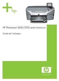
1.Unlock battery lock.<br />
2.Press battery switch and pull down to release<br />
battery.<br />
1. Remove the screws follow the sequence<br />
shown with screwdriver (T6).<br />
Torque: 1.2±0.2kgf-cm<br />
2. Remove the WLAN Cap from housing with<br />
plastic stick.<br />
Please follow the sequence as left shown when<br />
removing the screws.<br />
Use the plastic stick to separate the housing.<br />
Insert and gently twist into the gap between upper<br />
and lower case with the FLAT side <strong>of</strong> the tool.<br />
Please start from left then right side.<br />
Page 3
<strong>HP</strong>-00007-01, Appendix 3 13-Oct-2004<br />
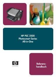
LCD F<strong>PC</strong><br />
Touch Pad F<strong>PC</strong> Button Cell Battery<br />
Rubbers<br />
Left Side<br />
1. Remove the screw (72H00338-00 ) with Philip<br />
screwdriver.<br />
Torque: 0.8±0.2kgf-cm<br />
2. Take out the tape and WLAN cable from<br />
WLAN board with tweezers gentlely.<br />
3. Remove the WLAN board from the connector<br />
<strong>of</strong> M/B with plastic stick.<br />
4. Remove the WLAN cable from the connector<br />
<strong>of</strong> Main BD with tweezers.<br />
1. Remove the LCD F<strong>PC</strong> and Touch Pad F<strong>PC</strong><br />
from the connectors <strong>of</strong> Main BD with tweezers<br />
gently.<br />
2. Remove the two screws (72H00401-00) with<br />
Philip screwdriver.<br />
Torque: 0.8±0.2kgf-cm<br />
3. Remove the M/B from the Bezel. Please<br />
watch out the audio jack under the process.<br />
4. Remove the button cell battery for selective<br />
treatment.<br />
1. Remove the LCM by release the hooks;<br />
please start from the left side then right side.<br />
It is not allowed to pull the<br />
LCM F<strong>PC</strong> under the process.<br />
2. Remove the rubbers (76H00639-00) on left<br />
side hooks <strong>of</strong> the bezel.<br />
Page 4
<strong>HP</strong>-00007-01, Appendix 3 13-Oct-2004<br />
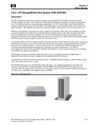
Disassemble the touch pad from the bezel.<br />
Page 5