LEAK MONITORS AND LEAK DETECTORS - Yellow Jacket
LEAK MONITORS AND LEAK DETECTORS - Yellow Jacket
LEAK MONITORS AND LEAK DETECTORS - Yellow Jacket

Create successful ePaper yourself
Turn your PDF publications into a flip-book with our unique Google optimized e-Paper software.
RECOVERY<br />
MACHINES<br />
VACUUM PUMP<br />
SYSTEMS<br />
VACUUM <strong>AND</strong><br />
CHARGING HOSES<br />
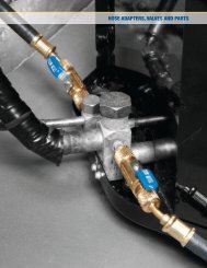
HOSE ADAPTERS,<br />
VALVES <strong>AND</strong> PARTS<br />
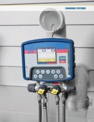
CHARGING<br />
SYSTEMS<br />
GAUGES<br />
ELECTRONIC<br />
INSTRUMENTS<br />
HEATING<br />
INSTRUMENTS<br />
<strong>LEAK</strong> <strong>MONITORS</strong><br />
<strong>AND</strong> <strong>DETECTORS</strong><br />
SYSTEM TOOLS<br />
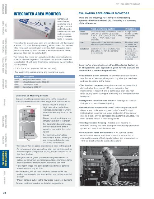
INTEGRATED AREA MONITOR<br />
Sensor and<br />
controller are<br />
combined into a<br />
single, compact<br />
unit that can be<br />
hard wired into any<br />
outlet or power<br />
supply to detect<br />
leaks in the area.<br />
The unit emits a continuous siren and constant red LED illumination<br />
at about 1000 ppm. This early warning allows time to find the leak<br />
while refrigerant concentration is still low. With adjustable delay,<br />
the monitor waits up to 15 minutes to avoid false alarms before<br />
signaling. Siren can be switched off.<br />
Two voltage-free relays can activate ventilation or remote alarms,<br />
or report to control systems. The monitor can also be connected<br />
to dedicated 16-unit panel (indefinitely expandable by connecting<br />
control panels).<br />
• 3.4" x 5.8" x 2.4" (86 mm x 147 mm x 61 mm)<br />
• For use in living spaces, marine and mechanical rooms<br />
UPC# Description<br />
68050 Integrated area monitor 115V<br />
68051 Integrated area monitor 220/240V<br />
68052 Control panel 115V<br />
68053 Control panel 220/240V<br />
Guidelines on Mounting Sensors<br />
Sensors must be powered according to the instruction<br />
manual and be within the cable length from the control unit.<br />
Ceiling<br />
Improper<br />
location in<br />
boiler room<br />
8" - 12"<br />
(20-30cm)<br />
16" - 20"<br />
(40.6-50.8cm)<br />
Floor<br />
• Do not mount in areas of<br />
high heat, direct solar heat,<br />
wetness, dampness or where<br />
condensation may form on the<br />
sensor<br />
• Do not mount to piping or any<br />
structure subject to vibration<br />
• For perimeter detection, place<br />
sensors around the area in<br />
question to monitor the entire<br />
space<br />
• For point detection, place<br />
sensor(s) at a point where you<br />
are concerned about a leak,<br />
i.e. at the compressor<br />
• For heavier than air gases, place sensors close to the ground<br />
• To help prevent false alarms from stray gas particles such as<br />
Volatile Organic Compounds (VOCs), mount sensors 16" to<br />
20" from the fl oor<br />
• For lighter than air gases, place sensors high on the walls or<br />
ceiling, but convenient for maintenance. Note: Ammonia is lighter<br />
than air at normal temperature but heavier in a cold room<br />
• Take room shape into consideration and mount sensors<br />
downstream of any air fl ow<br />
• In hot rooms, hot air rises to form a barrier below the<br />
ceiling and prevents gas from getting to a ceiling-mounted<br />
sensor<br />
• Mount sensors out of traffi c fl ow areas to prevent bumping<br />
Contact customer service for detailed suggestions.<br />
YELLOW JACKET HVAC&R<br />
EVALUATING REFRIGERANT <strong>MONITORS</strong><br />
There are two major types of refrigerant monitoring<br />
systems – Fixed and infrared (IR). Following is a summary<br />
of the differences:<br />
Fixed Monitoring System<br />
IR Systems<br />
Gases Measures a broad band of most common A single sensor<br />
Measured CFCs, HFCs, and HCFCs, such as: , must be used for<br />
R-11, R-12, R-13, R-22, R-113, R-134a, each specific<br />
R-407C, R-410A, R500, R-502<br />
refrigerant<br />
and R-507<br />
Cost Less than $500 per sensor to measure $1000 and more<br />
a broad range of refrigerants<br />
per sensor for<br />
each refrigerant<br />
Installation Controllers mount on any flat surface Plumbing tube<br />
and cable is run from the controller is used to reach<br />
to the sensor(s)<br />
sensing points.<br />
An additional<br />
tube for exhaust<br />
is required<br />
Once you’ve chosen between a Fixed Monitoring System or<br />
an IR System for your application, you’ll have to evaluate the<br />
features that a monitor might include.<br />
• Flexibility in size of controls – Controllers available for one,<br />
two, four or six sensors allow you to buy what you need now<br />
and plan to expand in the future<br />
• Two levels of response – A system can emit an intermittent<br />
alarm at a low level, about 100 ppm, indicating that<br />
maintenance is required, and a continuous siren at a high<br />
level, usually about 1000 ppm indicating that immediate action<br />
is required<br />
• Designed to minimize false alarms – Waiting until “certain”<br />
that gas is in the air before signaling<br />
• Individualized response by “zone” – Relay expander panel<br />
allows a four or six sensor system to be “zoned” for fast,<br />
individualized response in a larger application. If one sensor<br />
detects a leak, only its corresponding system is activated. The<br />
other sensors remain in monitoring mode<br />
• Sturdy protective housing – Coated steel housing for<br />
controller circuitry and ABS casing for sensors help protect the<br />
system and keep it maintenance-free<br />
• Protection in harsh environments – An optional vented<br />
environmental sensor enclosure protects a sensor that is<br />
mounted in an area of high condensation, low temperature to<br />
-40°F or direct airfl ow to avoid a false alarm<br />
78