AWB 02 009 Iss 1 - Repair and Maintenance Techniques for Wiring ...
AWB 02 009 Iss 1 - Repair and Maintenance Techniques for Wiring ...
AWB 02 009 Iss 1 - Repair and Maintenance Techniques for Wiring ...

Create successful ePaper yourself
Turn your PDF publications into a flip-book with our unique Google optimized e-Paper software.
AIRWORTHINESS BULLETIN<br />
<strong>AWB</strong> <strong>02</strong>-<strong>009</strong> <strong>Iss</strong>ue : 1<br />
<strong>Repair</strong> <strong>and</strong> <strong>Maintenance</strong> <strong>Techniques</strong> <strong>for</strong><br />
<strong>Wiring</strong> Systems Date : 29 July 2005<br />
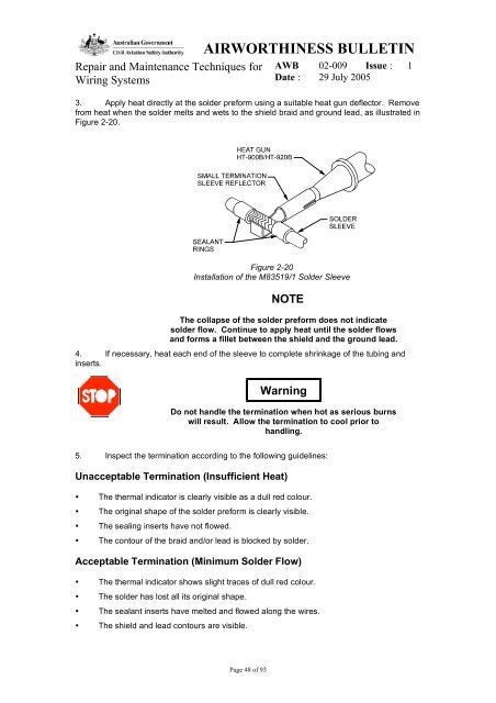
3. Apply heat directly at the solder pre<strong>for</strong>m using a suitable heat gun deflector. Remove<br />
from heat when the solder melts <strong>and</strong> wets to the shield braid <strong>and</strong> ground lead, as illustrated in<br />
Figure 2-20.<br />
Figure 2-20<br />
Installation of the M83519/1 Solder Sleeve<br />
NOTE<br />
The collapse of the solder pre<strong>for</strong>m does not indicate<br />
solder flow. Continue to apply heat until the solder flows<br />
<strong>and</strong> <strong>for</strong>ms a fillet between the shield <strong>and</strong> the ground lead.<br />
4. If necessary, heat each end of the sleeve to complete shrinkage of the tubing <strong>and</strong><br />
inserts.<br />
Warning<br />
Do not h<strong>and</strong>le the termination when hot as serious burns<br />
will result. Allow the termination to cool prior to<br />
h<strong>and</strong>ling.<br />
5. Inspect the termination according to the following guidelines:<br />
Unacceptable Termination (Insufficient Heat)<br />
• The thermal indicator is clearly visible as a dull red colour.<br />
• The original shape of the solder pre<strong>for</strong>m is clearly visible.<br />
• The sealing inserts have not flowed.<br />
• The contour of the braid <strong>and</strong>/or lead is blocked by solder.<br />
Acceptable Termination (Minimum Solder Flow)<br />
• The thermal indicator shows slight traces of dull red colour.<br />
• The solder has lost all its original shape.<br />
• The sealant inserts have melted <strong>and</strong> flowed along the wires.<br />
• The shield <strong>and</strong> lead contours are visible.<br />
Page 48 of 93