Installation Instructions RSR Bonneville Gear Indicator - RB Racing
Installation Instructions RSR Bonneville Gear Indicator - RB Racing
Installation Instructions RSR Bonneville Gear Indicator - RB Racing

You also want an ePaper? Increase the reach of your titles
YUMPU automatically turns print PDFs into web optimized ePapers that Google loves.
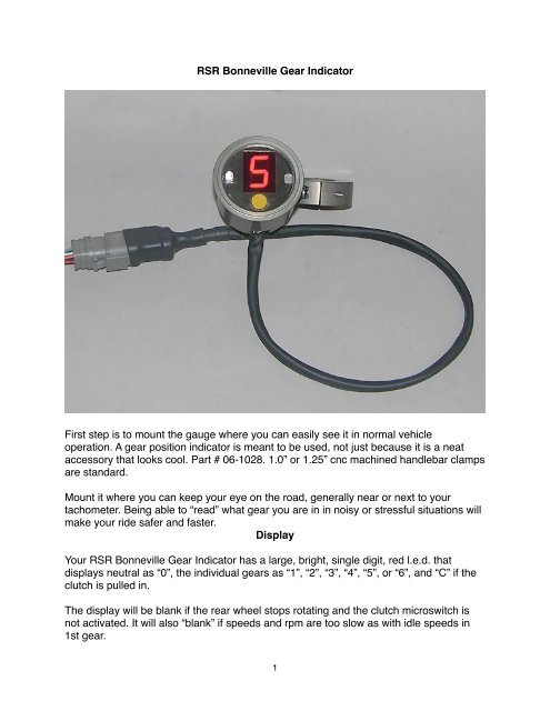
<strong>RSR</strong> <strong>Bonneville</strong> <strong>Gear</strong> <strong>Indicator</strong><br />
First step is to mount the gauge where you can easily see it in normal vehicle<br />
operation. A gear position indicator is meant to be used, not just because it is a neat<br />
accessory that looks cool. Part # 06-1028. 1.0” or 1.25” cnc machined handlebar clamps<br />
are standard.<br />
Mount it where you can keep your eye on the road, generally near or next to your<br />
tachometer. Being able to “read” what gear you are in in noisy or stressful situations will<br />
make your ride safer and faster.<br />
Display<br />
Your <strong>RSR</strong> <strong>Bonneville</strong> <strong>Gear</strong> <strong>Indicator</strong> has a large, bright, single digit, red l.e.d. that<br />
displays neutral as “0”, the individual gears as “1”, “2”, “3”, “4”, “5”, or “6”, and “C” if the<br />
clutch is pulled in.<br />
The display will be blank if the rear wheel stops rotating and the clutch microswitch is<br />
not activated. It will also “blank” if speeds and rpm are too slow as with idle speeds in<br />
1st gear.<br />
1
“L” will be displayed if you wish to reprogram the indicator. Simply hold down the button<br />
on the display before you “key on” and continue to hold the button down until “L” is<br />
displayed. Release the button and the unit can be programmed.<br />
Mounting<br />
The gauge is cnc machined billet enclosure with a back mounted 5/16” x 18 buttonhead<br />
cap screw. A total of four to seven wires are used to hook up the <strong>RSR</strong> <strong>Bonneville</strong> <strong>Gear</strong><br />
<strong>Indicator</strong>.<br />
Wiring...Four to Seven Wires<br />
1. Black Wire: Battery negative. Main ground system for the display. Use eyelet<br />
provided. Crimp black wire to eyelet and attach to battery negative terminal.<br />
2. Orange Wire : “Green” l.e.d. light. +12V Dc signal. Light will activate on +12V event.<br />
This is optional and does not need to be hooked up.<br />
2
3. ECU Connections on EFI Models:<br />
a. Light Blue Wire: Scotchlock to White/Green Stripe speed signal from transmission<br />
speed sensor leading to ECU. Split covering ECU harness to access the wire.Use<br />
non-adhesive harness wrap provided to cover Scotchlock on ecu harness. Wrap from<br />
“top” down and secure bottom of wrap with a plastic wire tie.<br />
3
For earlier models without a transmission speed sensor we offer a rear wheel sensor<br />
that “reads” the bolt heads on the rear wheel pulley.<br />
b. Pink Wire: Engine Speed signal. Scotchlock Pink wire to ECM Black Wire (Crank<br />
Sensor Negative signal) and use harness wrap to cover. Secure wrap with a plastic<br />
wire tie.<br />
c. Red Wire: +12V Dc switched power. When ignition or key “on” gauge is powered up.<br />
Typically this is Scotchlocked to the main power relay (Yellow Green Stripe). Use<br />
harness wrap to cover. Wrap from “top” down and secure bottom of wrap with a<br />
plastic wire tie.<br />
4. White Wire: “Neutral” signal. Signal is a ground event i.e. neutral switch on<br />
transmissions “ground” to activate neutral indicator lights. Neutral Switch is Tan wire on<br />
most later model bikes located in fairing or front instrument wiring. Scotchlock White<br />
wire to Tan Wire.<br />
5. Yellow Wire : “Clutch” activation signal. Signal is a ground event i.e. when clutch is<br />
pulled in a microswitch grounds the signal. Scotchlock Yellow Wire to Clutch grounding<br />
wire (Black/Red Stripe) in wire bundle leading from clutch lever. On vehicles without a<br />
switch <strong>RB</strong> <strong>Racing</strong> offers an an optional microswitch. For Harleys it is bolted below the<br />
clutch lever.<br />
Programming the <strong>RSR</strong> <strong>Bonneville</strong> <strong>Gear</strong> <strong>Indicator</strong><br />
The vehicle will have to be placed in neutral, started, and allowed to reach a stable<br />
operating temperature. The programming sequence requires that the vehicle be run<br />
through each gear. If you can securely place the motorcycle on a center stand where<br />
the vehicle can be shifted into all gears this is the best method. It can be also be<br />
programmed in actual on-road operation.<br />
On initial +12V activation the <strong>Gear</strong> <strong>Indicator</strong> will be ready to “learn”. The display will<br />
alternately slowly flash a “5” then “6”. You need to tell the display whether you have a<br />
five or six speed transmission.<br />
Simply push and hold the button “down” when the number matching your transmission<br />
appears. The number will stop flashing as you hold down the button. When the number<br />
you chose ( “5” or “6”) begins flashing quickly, release the button and the number “1” will<br />
slowly flash.<br />
The <strong>RSR</strong> <strong>Bonneville</strong> <strong>Gear</strong> <strong>Indicator</strong> now knows whether your transmission has five or<br />
six gears. With the “1” slowly flashing, you are ready to program first gear.<br />
The following sequence will be repeated for each of the five or six gears:<br />
4
1. Put the motorcycle in 1st gear and release the clutch.<br />
2. Wait for the wheel to begin rotating and insure the vehicle is a safe and stable.<br />
3. Press and hold the button “down”. Do not release the button.<br />
4. The number of the gear you are programming will stop flashing as you hold down the<br />
button.<br />
5. When the display begins to quickly flash again it has learned that gear. Now release<br />
the button.<br />
6. The display will now begin slowly flashing the next “gear number”...in the case “2”.<br />
7. Put the motorcycle into second gear and repeat the process above i.e. hold the<br />
button down, the number “2” will stop flashing and release the button when “2” begins<br />
quickly flashing.<br />
8. When the last gear (5th or 6th) has been programmed the process is finished.<br />
9. If you make a mistake before you finish the last gear you can simply turn the engine<br />
off and start the process over.<br />
Setting Automatic Display Night Dimming<br />
5
During daylight operation the display needs to be at full brightness. At night the display<br />
needs to be dimmed to avoid a blinding distraction.<br />
You set the point at which the display dims from full brightness in the following steps:<br />
1. In light conditions where it is not yet completely dark but is in transition such as at<br />
dawn, nightfall, or in a dimly lit situation, turn on the ignition and place the<br />
transmission in neutral. The display will show a “0” indicating the bike is in neutral.<br />
2. Press and hold down the programming button for one second until the display begins<br />
to flash. Be careful not to cover the photo cell window (wavy lines). Release the<br />
button.<br />
3. Now the display will switch to dim whenever these or “darker” conditions are present.<br />
Reprogramming/ Resetting the <strong>RSR</strong> <strong>Bonneville</strong> <strong>Gear</strong> <strong>Indicator</strong><br />
6
To force a new learning situation for whatever reason or perhaps when you move the<br />
gear indicator to another bike, simply hold the button down before you power up the<br />
display.<br />
Continue to hold the button down until “L” is displayed, then release the button. You may<br />
now follow the normal steps listed on page 5 to program the <strong>RSR</strong> <strong>Bonneville</strong> <strong>Gear</strong><br />
<strong>Indicator</strong>.<br />
__________________________________________<br />
It is wise to check the wiring diagram for your bike before you connect the <strong>Gear</strong><br />
<strong>Indicator</strong>. The tach signal is compatible with most OEM and aftermarket ECM/ECU or<br />
ignition systems.<br />
7