Precision Products Aircraft Circuit Breakers - Sensata
Precision Products Aircraft Circuit Breakers - Sensata
Precision Products Aircraft Circuit Breakers - Sensata
- No tags were found...

Create successful ePaper yourself
Turn your PDF publications into a flip-book with our unique Google optimized e-Paper software.
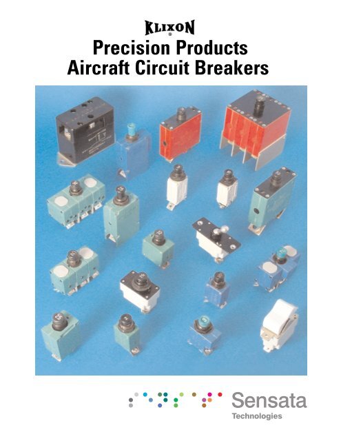
I N N O V A T I V SEO L U T I O N ISN S E N S O R S A N D C O N T R O L S<strong>Precision</strong> <strong>Products</strong><strong>Aircraft</strong> <strong>Circuit</strong> <strong>Breakers</strong>
Condensed <strong>Aircraft</strong> <strong>Circuit</strong> Breaker GuideCIRCUITBREAKERTYPENUMBERFAULTINTERRUPTINGCAPACITYAMPS @VOLTS& CYCLESREMARKSTYPICAL APPLICATIONS2TC3TC5TC6TC9TC2TC493TC76752-126752-1006752-305727472777270727120TC23SB6000 @ 28 VDC2500 @ 120 VAC, 400 Hz6000 @ 28 VDC2000 @ 120 VAC, 400 Hz4000 @ 28 VDC2000 @ 115 VAC, 400 Hz2000 @ 120 VAC, 400 Hz2000 @ 120 VAC, 400 Hz6000 @ 28 VDC2500 @ 120 VAC, 400 Hz6000 @ 30 VDC3500 @ 120 VAC, 400 Hz6000 @ 30 VDC120 VAC, 400 Hz2000 @ 28 VDC500 @ 125 VAC, 400 Hz2000 @ 28 VDC500 @ 120 VAC, 400 Hz4000 @ 30 VDC3500 @ 120 VAC, 400 Hz2000 @ 30 VDC1000 @ 120 VAC, 400 Hz––Subminiature,ambient compensated 1 poleauxiliary switch availableAmbient compensatedSubminiature,ambient compensated, 3 poleDual Safety 2TCLightweight, high performance,non-ambient temperaturecompensated1 Pole – 6752-121 Pole – 6752-1003 Pole – 6752-305Quick acting, subminiatureauxiliary switch availableWide calibrationversion of 7274Toggle or push buttonRocker switch typePush button<strong>Aircraft</strong> power distribution<strong>Aircraft</strong>, avionics, and electrical systems<strong>Aircraft</strong> power distribution<strong>Aircraft</strong> power distribution<strong>Aircraft</strong>, avionics, and electrical systems<strong>Aircraft</strong> power distributionground support<strong>Aircraft</strong> power distribution,Avionics, ground support, missile systemsProtection of wire, motors, solenoids,transformers in electronics<strong>Aircraft</strong> power distributionCombination circuit switching & protectionlight aircraft, electronics, vehiclesCommercial and military simulators*Note: For FAA/PMA approved devices, go to www.klixon.comFor more information contact our product manager:Tel: (508) 236-3573For more information on circuit breakers contact:Tel: (508) 236-3536Website address: www.sensata.com
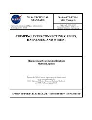
Characteristics2TC14 / 3TC142TC143TC14Panel Mounting.125±.005 Dia.Panel Mounting.125±.005 Dia..031.078.375 OFMOUNTING KEYCL.75055 AMPRATINGSHOWN.562MAX..375±.005.485±.005 Dia..031.078.375 OFMOUNTING KEYCL1.100MAX.35.781MAX.35 AMPRATINGSHOWN.375±.005.485±.005 Dia..04715/32-32UNS-2A.25015/32-32UNS-2A.2501.030MAX. 1.218.0471.030MAX. 1.218.704#8-32 UNC.704#8-32 UNCCalibration: 1-25 ampsCalibration: 15-35 ampsTEMPo C+25-54+121MIN ULTTRIP115%115%85%MAX ULTTRIP138%165%145%TRIP TIME - SECONDS200%4-167-352-13500%.4-1.6.6-3.0.25-1.01000%.10-.40.15-.70.06-.25TEMPo C+25-54+121MIN ULTTRIP115%115%85%MAX ULTTRIP138%165%145%TRIP TIME - SECONDS200%4-206-352-15500%.40-1.7.55-3.0.25-1.01000%.10-.40.15-.70.06-.25Vibration*....................... 10 G’s minimum, 50 - 500 HzMechanical Shock.......... 50 G’sAcceleration................... 10 G’sWeight............................. 2TC14 - 24 gm max.3TC14 - 36 gm max.Interrupt Current1-20 amps: 6000 amps at 28 VDC25 amps: 1625 amps at 28 VDC1-15 amps: 2500 amps at 120 VAC, 400 Hz20 amps: 2000 amps at 120 VAC, 400 Hz25 amps: 1800 amps at 120 VAC, 400 HzEndurance2500 cycles 120 VAC, 400 Hz Inductive5000 cycles 120 VAC, 400 Hz Resistive2500 cycles 30 VDC Inductive5000 cycles 30 VDC Resistive10,000 cycles Mechanical, no load* Other vibration levels available. Contact factory for details.<strong>Sensata</strong>Number2TC14-12TC14-22TC14-2 1 ⁄22TC14-32TC14-42TC14-52TC14-7 1 ⁄22TC14-102TC14-152TC14-202TC14-25VoltageDrop (max.)**1.100.700.500.400.450.350.300.280.250.250.20**Max. voltage drop at nominal rated current.<strong>Sensata</strong>Number3TC14-153TC14-203TC14-253TC14-303TC14-35VoltageDrop (max.)**0.250.250.250.250.251000Approximate Time-Current Curves - 2TC and 3TC <strong>Circuit</strong> <strong>Breakers</strong>-54 o C MAXIMUM TRIP CURVE% Rated Current100+121 o C MINIMUM TRIP CURVE+25 o C TRIP BAND165%138%115%85%0.01 0.1 1 10 100 1000Trip Time in Seconds
Three Phase TC Series <strong>Circuit</strong> <strong>Breakers</strong>Miniature Ambient CompensatedFeatures• One phase trips all• Protective shields between eachphase’s terminals• Pads increase mounting stability• Also includes identical featuresas 2TC and 3TC6TC9TCOverviewThe 6TC and 9TC circuit breakersprovide ambient compensatedcircuit protection in a lightweight,subminiature package size. Thethree phase design integrateseach individual phase to provideovercurrent protection in theevent of simultaneous orunbalanced overloads, includingshort circuit conditions.CoordinationThe 6TC and 9TC are compatiblewith their single phase 2TC and3TC cousins. The 6TC and 9TCare available in ratings from 1-35amps, with military and variouscommercial approvals on moststyles.Ambient TemperatureCompensationThe 6TC and 9TC are ambientcompensated circuit breakers. Thisallows usage of smaller gauge wire.The 6TC and 9TC can operateover a temperature range of-54 o C to 121 o C, however, careshould be taken to understand thespecification limits at elevatedambient temperatures.Options*• Longer push buttons• High vibration• Metric mounting thread• Metric terminal thread• Dust boot†• Auxiliary switch device available††* Contact factory for details† Part Number 14500-1 fits 15/32 bushingPart Number 14500-5 fits 7/16 bushing†† 6TC DeviceTrip FreeThe complete line of TC seriescircuit breakers is trip free. Thecircuit breaker cannot be maintainedclosed during an overload,even with the actuator buttonheld closed.High Short <strong>Circuit</strong> CapacityFor its miniature size, the 6/9TCseries offers unusually highcurrent interrupting capacity.Overloads up to 2000 amps at120 VAC, 400 Hz can be safelyinterrupted without affectingcalibration or operatingperformance in the standard6/9TC series.QualificationsMS14154 6TC2MS14154L 6TC37MS14154V 6TC63MS14153 9TC2European standardsSAE standardsAll U.S. aircraft OEM’sMost European aircraft OEM’s
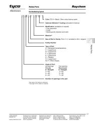
Characteristics6/9TC6TC14 Panel Mounting 9TC14Panel Mounting.125±.005 Dia. .125±.005 Dia.1.8405 AMP RATING SHOWN2.41535 AMP RATING SHOWN5.375±.005.485±.005 Dia.351.100MAX..375±.005.485±.005 Dia.15/32 .32UNS 2A 15/32 .32.047.047UNS 2A.250 .2501.030MAX1.2181.3501.030MAX.1.218.500.624.7651.100MAX.#8-32 UNC.802.765#8-32 UNCCalibration: 2-20 ampsTEMPo C+25-54+90+121MIN ULTTRIP110%110%100%90%MAX ULTTRIP145%165%145%145%TRIP TIME - SECONDS200%4-206-403-203-20500%.40-2.0.55-3.5.33-1.7.33-1.71000%.10-.53.15-.80.08-.40.08-40† Single phase max. ult. trip values apply with other two phases carrying 100% ofrated current.Calibration: 1, 15-35 ampsTEMPo C+25-54+90+121MIN ULTTRIP110%110%100%90%MAX ULTTRIP145%165%145%145%TRIP TIME - SECONDS200%4-206-403-203-20500%.40-2.0.55-3.5.33-1.7.33-1.71000%.10-.53.15-.80.08-.40.08-40† Single phase max. ult. trip values apply with other two phases carrying 100% ofrated current.Vibration* ................................Mechanical Shock ...................Acceleration ............................Weight .....................................10 G’s minimum, 50-500 Hz50 G’s10 G’s6TC14 - 65 gm max.9TC14 - 110 gm max.Interrupt Current2-20 amps: 2000 amps at 120 VAC, 400 Hz1, 15-35 amps: 2000 amps at 120 VAC, 400 HzEndurance2500 cycles ................................... 120 VAC, 400 Hz Inductive5000 cycles ................................... 120 VAC, 400 Hz Resistive5000 cycles ................................... Mechanical, no load* Other vibration levels available. Contact factory for details.<strong>Sensata</strong>Number6TC14-26TC14-2 1 ⁄26TC14-36TC14-46TC14-56TC14-7 1 ⁄26TC14-106TC14-156TC14-20Voltage Drop(max.)0.700.500.400.370.35.192.176.176.176** Max voltage drop at nominal rated current.(25 amp 6TC pending qualification.)<strong>Sensata</strong>Number9TC14-19TC14-159TC14-209TC14-259TC14-309TC14-35Voltage Drop(max.)**1.100.250.250.250.250.25% Rated Current1000100Approximate Time-Current Curves - 6TC and 9TC <strong>Circuit</strong> <strong>Breakers</strong>+90 o C MINIMUM TRIP CURVE-54 o C MAXIMUM TRIP CURVE+25 o C TRIP BAND.01 0.1 1.0 10 100 1000Trip Time in Seconds165%145%110%100%
2TC49 Series“Dual Safety” <strong>Circuit</strong> <strong>Breakers</strong>Features• Extension of 2TC series• Redundant protection in hard faultcatastrophic conditions• Separable link feature• Case color distinguishes 2TC49 from 2TC series• Uses less space and weighs less than othercircuit breaker packages• Rating 2 1 ⁄2 -15 amps2TC49“Dual Safety” <strong>Circuit</strong> BreakerOverviewThe 2TC49 “Dual Safety” circuitbreaker represents a refinementin electrical control and circuitprotection. The 2TC dual safetycircuit breaker incorporates afusible element in a standard 2TC(MS 3320) package size toprovide redundant protection inhard fault conditions.“Hard Fault” TrippingThe 2TC dual safety circuitbreaker operates identically to astandard circuit breaker under allnormal conditions, includingshort circuit. In the event ofcircumstances which disable theinternal circuit breakermechanisms, such that the deviceis able to carry current but unableto clear an overload via its normalmeans, the dual safety elementacts as a built in fuse to provideredundant circuit protection.The key part in the dual safetydesign is a two part currentcarrying element joined by aspecial alloy. The geometry andmaterial of the element determineits heating properties. Theelements heating properties areslower than the bimetal sensorbut faster than the smoke curveof the wire the rating is designedto protect. In the case where thestandard mechanism is disabledor cannot operate normally, theseparable element “fuses” open,interrupting the current.The benefits of the dual safetydesign result in calibratedovercurrent protection (basedon fuse times) and specified postfuse dielectric properties forsystem and human protection.
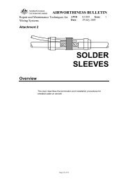
Characteristics2TC49.562.083.073CENTER LINE OF MOUNTINGKEY .370-.380.250.055.040.400 DIA..3901.312 1.030 MAX.1.218.036.0265.781.71947 o –43 o .281.219.531.4695 AMPRATING SHOWNCASE COLORBLUE5 AMP RATINGSHOWNBREAKER IN CLOSEDPOSITION7/16-32NS-2A THREAD#8-32 UNCPanel Mounting.125±.005 Dia..375±.005BREAKER IN OPEN POSITION.250.750 MAX.BLACK.445±.005 Dia.Link Separation CharacteristicsMaximum circuit breaker link separation times for locked contactcondition as a function of overloadAmp RatingTempo C+25-54+1212 1 ⁄2357 1 ⁄210400%–––69.060.0Min ULTTrip115%115%90%500%––95.028.035.0Calibration: 2 1 ⁄2–15 amps% Overload Rated Current600%34.034.036.014.020.0Max ULTTrip138%165%138%“Dual Safety” 2TC49700%20.020.018.08.012.0Time (seconds)200%5-207-403-13800%13.013.010.04.07.0900%9.09.06.03.54.0Trip Time – Seconds500%.5-2.0.6-3.0.33-1.11000%6.06.03.52.02.51000%.12-.53.16-.8.07-.3Vibration* ..................................Mechanical Shock .....................Acceleration ..............................Weight .......................................10 G’s minimum, 50-500 Hz50 G’s10 G’s2TC49 - 25 gm max.Post-short circuit dielectric ......................................1125 VAC Min (1mA)Post-link separation dielectric .......................................... 900 VAC (1mA)Interrupt Current2 1 ⁄2 - 15 amps: 6000 amps at 28 VDC2 1 ⁄2 amps: 2800 amps at 120 VAC, 400 Hz3 - 15 amps: 2500 amps at 120 VAC, 400 HzEndurance2500 cycles ................................ 120 VAC, 400 Hz Inductive5000 cycles ................................ 120 VAC, 400 Hz Resistive2500 cycles ................................ 30 VDC, Inductive5000 cycles ................................ 30 VDC, Resistive10,000 cycles ............................. Mechanical, no load* Other vibration levels available. Contact factory for details.<strong>Sensata</strong>Number2TC49-2 1 ⁄22TC49-32TC49-52TC49-7 1 ⁄22TC49-10Voltage Drop(max.)**0.700.550.350.300.28** Max. voltage drop at nominalrated currentApproximate Time-Current Curves - 2TC49 <strong>Circuit</strong> <strong>Breakers</strong>1000-54 o C MAXIMUM TRIP CURVE% Rated Current+121 o C MINIMUM TRIP CURVE+25 o C TRIP BAND165%138%115%90%1000.01 0.1 1 10 100 1000Trip Time in Seconds
Characteristics5TCOptional Aux. Switch.059.260Panel Mountingø .492 ±.005ø .138 ±.00550 AMP RATINGSHOWN1.653 MAX.1.2991.9202.170 MAX.1.102 MAX.1.575.768 MAX. .622 MAX.50.375 ±.005.378.827Calibration: 20-50 AmpsTemp o C+23-54+70+125Min. ULT.Trip110%110%105%90%Max. ULT.Trip145%165%145%145%200%2-1870 sec. max.1.5 sec. min.1.5 sec. min.Trip Time - Seconds500%.15 - 2.5.15 - 2.5.15 - 2.5.15 - 2.51000%.045 - .6.045 - .6.045 - .6.045 - .6The above calibration chart is representative of a standard commercial device. <strong>Sensata</strong> offers specific variants with similarperformance dependant on military or customer specifications. Temperatures are ±5 o C.Interrupting Capacity20-50 amps......4000 amps at 28 VDC20-50 amps..... 2000 amps at 115 VAC,400 HzEndurance2500 cycles...........115 VAC, 400 Hz,Inductive2500 cycles...........28 VDC, Inductive2500 cycles...........28 VDC, Resistive5000 cycles...........Mechanical, no loadPerformanceVibration .....................................Mechanical Shock ........................Acceleration .................................WeightStandard Device .....................Auxiliary Device .....................10 G’s minimum, 80-500 Hz50 G’s10 G’s53 grams (w/o hw), 58 grams (w/hw)55 grams (w/o hw), 59 grams (w/hw)Amp Rating20253550Voltage Drop (max)*0.1500.1500.1500.120* Max. voltage drop at nominal rated current% Rated Current2010521Approximate Time-Current Curves - 5TC <strong>Circuit</strong> <strong>Breakers</strong>+125 o C MINIMUM TRIP CURVE+23 o C TRIP BAND -54 o C MAXIMUM TRIP CURVE.01 .1 1 10 100 1000Trip Time in Seconds
6752 Series <strong>Circuit</strong> <strong>Breakers</strong>Ambient Compensated Single & Three Phase High Short <strong>Circuit</strong> CapacityFeatures• Useable on large electrical systems – 6000 amperesinterrupting capacity• <strong>Circuit</strong> protection unaffected by temperaturefluctuation – ambient compensated from-65 o F to +250 o F• Only faulted line circuits opened – coordination ofratings ensures that branch circuit breakers tripfirst under fault conditions• Long trouble-free operation – 20,000 operating cycles• Military approved• High amp devices available (65A & 90A)6752-126752-300OverviewThe Klixon 6752-12 and -300series thermal-magnetic circuitbreakers are ambient compensatedand trip-free. They are designedand manufactured to meet themore stringent military standardsof today’s jet aircraft, specificallyMIL-DTL-22715.The higher short circuit capacity,vibration resistance and longercycling life of the 6752-12 and-300 series exceed previousmilitary standards. In addition,the 6752-12 and -300 seriesprovide ambient compensation,fault coordination of all ratings,and an option for auxiliary circuits.High Short <strong>Circuit</strong> CapacityA deionizing grid and magneticassist enable the 6752-12 and-300 series to successfullyinterrupt four fault currents of6000 amperes – two at sea leveland two at 60,000 feet – on either a120 VAC , 400 Hz system or a 30 VDCsystem.Ambient TemperatureCompensationSubstantially unaffected byambient temperature, the 6752-12and -300 series circuit breakersmaintain their performance capabilitiesby means of a thermalcompensator in the temperaturerange of -54 o C to+121 o C.CoordinationThe 6752-12 and -300 seriesbreaker ratings are coordinatedso any rating will trip beforeanother rating, twice its capacity,in the event of a fault. Thisresults in improved over-allequipment performance, sinceonly the smallest faulted circuitis removed while larger circuitsremain in operation.Auxiliary <strong>Circuit</strong>The 6752-12 and -300 series areavailable with auxiliary switch.For part numbers and characteristics,please consult the factory.MIL Qualification<strong>Sensata</strong>Number MS Number6752-12-2 1 ⁄26752-12-56752-12-7 1 ⁄26752-12-106752-12-156752-12-206752-12-256752-12-356752-12-50MS 24571-2 MS 24571-2VMS 24571-5 MS 24571-5VMS 24571-7 MS 24571-7VMS 24571-10 MS 24571-10VMS 24571-15 MS 24571-15VMS 24571-20 MS 24571-20VMS 24571-25 MS 24571-25VMS 24571-35 MS 24571-35VMS 24571-50 MS 24571-50VWhen ordering MS 24571-XX(V) style breaker by<strong>Sensata</strong> part number, designator must includeS.R. 12507-356Example: 6752-12-2 1 ⁄2 is S.R. 12507-356
CharacteristicsEnvelope Dimensions#6-32 UNC SCREWS.750 MAX.4X R .0902.189 MAX.1.083.911.9011.8171.807.460MIN.6–32UNC–2BSELF-LOCKING NUT(2 REQ’D)(.312 MIN DEPTH)2.560MAX.(CLOSED POSITION).115.0352.3571.930MAX..7356752-100.427 MS35308-303.250 – 28UNF-2B INTEGRAL.395 .250 – 28UNF-2A X .500L ALL-METAL LOCKING NUTCAP SCREW WITH (2 REQ’D)FLAT WASHER(2 REQ’D)DETAIL.060 min.47 o43 o1.470Performance CharacteristicsVibration* .....................................Mechanical Shock .....................Acceleration ................................Weight ...........................................Interrupt Current120 VAC, 400 Hz: 3500 amps28 VDC: 6000 ampsEndurance5000 cycles .................................. 120 VAC, 400 Hz Resistive5000 cycles .................................. 120 VAC, 400 Hz Inductive5000 cycles .................................. 28 VDC, 400 Hz Resistive2500 cycles .................................. 28 VDC, 400 Hz Inductive5000 cycles .................................. no load* Other vibration levels available. Contact factory for details.10 G’s minimum, 50-2000 Hz30 G’s10 G’s0.25 lbs (114 gm) max.6752-100 CalibrationTempo C+25-40+70Min ULTTrip105%125%70%Max ULTTrip138%165%125%200%15-6515-6515-65Trip Time – Seconds400%2-102-102-101000%1.41.41.410,000Approximate Time-Current Curves – 6752-100 <strong>Circuit</strong> <strong>Breakers</strong>% Rated Current1000100UPPER LIMITAT –40 o C165%138%105%70%100.01 .01 1 10 100 1000Trip Time in SecondsLOWER LIMITAT 70 o C
3TC7 SeriesSingle Phase, Non Ambient Compensated, High Short <strong>Circuit</strong> Interrupting CapacityFeatures• Lightweight• Miniature size• High interrupting capacity• High vibration resistance• Available in 5-35 amperes3TC7OverviewDetailed Performance DataThe Klixon 3TC7 style circuitbreaker is a lightweight, highperformance, non ambienttemperature compensated circuitbreaker that is well suited foraircraft, avionics and electricalsystems. The 3TC7 series featuresa trip free design that preventsthe circuit breaker from beingclosed manually on overloads.The 3TC7 interrupting a 6,000Acircuit at 30 VDC, or 3,500A circuitat 120 VAC, 400 Hz.The Klixon trademark continues toset the standard for lightweightconfigurations and offers theendurance and reliability requiredby exacting military specifications.The 3TC7 is currently available in5-35 amperes.Interrupting CapacityEnduranceVibrationMechanical ShockAccelerationWeightOperating Altitude<strong>Sensata</strong> Number3TC7-53TC7-7 1 ⁄23TC7-103TC7-153TC7-203TC7-253TC7-303TC7-35MS Number6000 Amperes at 30VC120 VAC, 400 Hz Inductive120 VAC, 400 Hz Resistive30 VDC, Inductive30 VDC, ResistiveMechanical, no load10 G’s30 G’s peak10 G’s39 gm65,000 ftMS25244-5MS25244-7 1 ⁄2MS25244-10MS25244-15MS25244-20MS25244-25MS25244-30MS25244-35Amp Rating57 1 ⁄21015202530353500 Amperes at120 VAC, 400 Hz2,500 Cycles5,000 Cycles2,500 Cycles5,000 Cycles5,000 CyclesVoltage Drop.25.25.25.25.25.25.25.25
Characteristics3TC71.094MAX.35 AMP RATING SHOWN.07835.750 MAX..375 OF MOUNTING KEY CBREAKER IN CLOSED POSITIONBREAKER IN OPEN POSITIONø .330MS25082-C21BLACKWHITE.240MS35338-136BLACK.1201.741.491.86MAX..704MS51957-41Calibration+25 o C-40 o C+71 o CMin Ult Trip115%148%70%Max Ult Trip138%178%114%200%15 - 55 sec--400%2.0 - 7.0 sec--600%1.0 - 3.5 sec--1000Approximate Time-Current Curve 3TC7 <strong>Circuit</strong> <strong>Breakers</strong>% Rated Current100115%138%100.1 1 10 100 1000Trip Time in Seconds
7274 Series <strong>Circuit</strong> <strong>Breakers</strong>Low Amperage, High PerformanceFeatures• Uses minimum space• Light weight• Ratings: 1/2 – 20 amperes• Military approved7274-27274-4 7274-11 and 7274-69OverviewThe 7274 series are small, lightweight, low amperage devices thatare specifically designed toprotect aircraft / aerospace cablesuch as flat ribbon, fusedmulti-conductor tape and printedcircuit conductors now being usedin lighter weight powerdistribution systems and componentsin airborne vehicles andequipment.The 7274 series features a tripfreeindicating-type reset button.Also, a “wiping action” contactdesign assures low voltage drop,faster trip time and high reliabilityin low voltage applications. Theyare available in standard ratingsfrom 1/2 – 20 amps.A water resistant panel seal*designed to fit over the pushbutton actuator is available forapplications that require this typeof protection.OptionsLong push buttonsAuxiliary switchWaterproof panel sealHigh vibration* Part number 14500-1 fits 7274-11 and other typeswith 15/32” mounting bushing.14500-5 fits 7274-2 (7/16”).<strong>Sensata</strong> Number7274-2- 1 ⁄27274-2- 3 ⁄47274-2-17274-2-1 1 ⁄27274-2-27274-2-2 1 ⁄27274-2-37274-2-47274-2-57274-2-7 1 ⁄27274-2-107274-2-157274-2-20MS NumberMS 26574- 1 ⁄2MS 26574- 3 ⁄4MS 26574-1MS 26574-1 1 ⁄2MS 26574-2MS 26574-2 1 ⁄2MS 26574-3MS 26574-4MS 26574-5MS 26574-7 1 ⁄2MS 26574-10N/AN/A<strong>Sensata</strong> Number7274-4- 1 ⁄27274-4- 3 ⁄47274-4-17274-4-1 1 ⁄27274-4-27274-4-2 1 ⁄27274-4-37274-4-47274-4-57274-4-7 1 ⁄27274-4-107274-4-157274-4-20<strong>Sensata</strong> Number7274-11- 1 ⁄27274-11- 3 ⁄47274-11-17274-11-1 1 ⁄27274-11-27274-11-2 1 ⁄27274-11-37274-11-47274-11-57274-11-7 1 ⁄27274-11-107274-11-157274-11-20MS NumberMS 22073- 1 ⁄2MS 22073- 3 ⁄4MS 22073-1MS 22073-1 1 ⁄2MS 22073-2MS 22073-2 1 ⁄2MS 22073-3MS 22073-4MS 22073-5MS 22073-7 1 ⁄2MS 22073-10N/AN/A<strong>Sensata</strong> Number7274-69- 1 ⁄27274-69- 3 ⁄47274-69-17274-69-1 1 ⁄27274-69-27274-69-2 1 ⁄27274-69-37274-69-47274-69-57274-69-7 1 ⁄27274-69-107274-69-157274-69-207274-70 Qualified to MS 26547L for ratings 1/2 amp to 10 amp.MS NumberMS 26574- 1 ⁄2AMS 26574- 3 ⁄4AMS 26574-1AMS 26574-1 1 ⁄2AMS 26574-2AMS 26574-2 1 ⁄2AMS 26574-3AMS 26574-4AMS 26574-5AMS 26574-7 1 ⁄2AMS 26574-10AN/AN/AMS NumberMS 22073- 1 ⁄2VMS 22073- 3 ⁄4VMS 22073-1VMS 22073-1 1 ⁄2VMS 22073-2VMS 22073-2 1 ⁄2VMS 22073-3VMS 22073-4VMS 22073-5VMS 22073-7 1 ⁄2VMS 22073-10VN/AN/A
Characteristics72747274-2 and 7274-4 7274-11 and 7274-69Panel Mounting.7503.562.562PUSH PULL BUTTON POSITION WITHCIRCUIT BREAKER TRIPPED (OFF).213.359 .277 MAX.1.3021.115.10045 o .5933 AMP RATING SHOWN.440.445.032.191.744.419.388KEYWAY WASHER DETAIL#6–32 UNC SCREWS.110.0787/16-32NS-2 THREADMOUNTING NUTLOCK WASHERKEYWAY WASHERBACK-UP NUTLOCK WASHERPHILLIPS RECESSPAN HEAD SCREWAUXILIARY TERMINAL 7274-4 ONLY.125±.005 Dia..375±.005.050 DIAHOLE.445±.005 Dia..75033 AMP RATING SHOWN.032.718.472.203.562.390.078.093KEYWAY WASHER DETAIL.410PUSH PULL BUTTON POSITION WITHDIA..100CIRCUIT BREAKER TRIPPED (OFF).480.25515/32-32NS-2 THREAD.250MOUNTING NUT.191LOCK WASHER1.707KEYWAY WASHER1.450PHILLIPS RECESSPAN HEAD SCREWLOCK WASHER45 o .703#8–32 UNC SCREWSPanel Mounting.125±.005 Dia..375±.005.485±.005 Dia.Vibration* .....................................Mechanical Shock ........................Acceleration .................................Weight ..........................................Interrupt Current1/2 - 5 amps: unlimited at 28 VDC7 1 ⁄2 - 15 amps: 2000 amps at 28 VDC1/2 - 1 1 ⁄2 amps: 800 amps at 120 VAC, 400 Hz2 - 5 amps: 800 amps at 120 VAC, 400 Hz7 1 ⁄2 - 20 amps: 500 amps at 120 VAC, 400 HzEndurance2500 cycles ................................. 120 VAC, 400 Hz Inductive5000 cycles ................................. 120 VAC, 400 Hz Resistive2500 cycles ................................. 30 VDC, Inductive5000 cycles ................................. 30 VDC, Resistive5000 cycles ................................. Mechanical, no load* Other vibration levels available. Contact factory for details.100010 G’s minimum, 50-500 Hz35 G’s10 G’s minimum7274-2: 28 gm max.7274-4: 28 gm max.7274-11: 33 gm max.7274-69: 33 gm max.Calibration: 1/2–20 ampsTempo C+25-55+71Approximate Time-Current Curves 7274 <strong>Circuit</strong> <strong>Breakers</strong>Min ULTTrip115%135%90%Max ULTTrip150%180%130%<strong>Sensata</strong> Number7274-XX- 1 ⁄27274-XX- 3 ⁄47274-XX-17274-XX-1 1 ⁄27274-XX-27274-XX-2 1 ⁄27274-XX-37274-XX-47274-XX-57274-XX-7 1 ⁄27274-XX-107274-XX-157274-XX-20200%2-20––Trip Time – Seconds500%.16-1.2––Voltage Drop(Max.)**2.001.451.100.750.750.700.550.450.350.300.280.250.25**Max voltage drop at nominal rated current.UPPER LIMIT AT -55 o C1000%.046-.8––% Rated Current100LOWER LIMIT AT 71 o C180%150%115%90%100.01 0.1 1 10 100 1000Trip Time in Seconds
7277 Series <strong>Circuit</strong> <strong>Breakers</strong>Low Amperage, General ApplicationFeaturesThe 7277 series is designed for applications that do notrequire the tighter performance characteristics andapprovals of our military circuit breakers.• Small size• Light weight• Inexpensive• Auxiliary switch• Longer push buttons7277-27277-1OverviewThe 7277 series circuit breaker isphysically and electrically identicalto the 7274-2 style circuit breaker,with the exception that the 7277series has wider calibration limits.Originally developed as an alternativeto slow blow fuses, the tripfree 7277 is used extensively asprimary electrical circuit protectionon general aviation aircraft.The wider calibration limits of the7277 has also resulted inapplications including protectionfor data processing andtelecommunications equipment,computers, flight simulators,construction, material handlingand other industrial,electronicequipment.For use on trainer / simulatorapplications where all breakersare operated on low amperecontrol current, different ampererating inserts (amp ratings on topof push button) can be ordered.Use TI part number 27515.(Refer to 7274-2 and 7274-4dimensions on previous page.)Code System<strong>Sensata</strong>Number7277-2- 1 ⁄27277-2- 3 ⁄47277-2-17277-2-1 1 ⁄27277-2-27277-2-2 1 ⁄27277-2-37277-2-47277-2-57277-2-7 1 ⁄27277-2-107277-2-157277-2-207277 – 2 – 5Basic typeDerivative7277 –1: Aux. switch versionOrdering InformationAmpereRating1/23/411 1 ⁄222 1 ⁄23457 1 ⁄2101520**Max voltage drop at nominal rated current.Ampere rating(i.e., 5 = 5 amps,7 1 ⁄2 = 7 1 ⁄2 amps)Max. Drop**(volts)2.001.451.100.750.700.500.330.300.250.200.150.150.15% Rated Current1000100Calibration: 1/2–20 amps*Tempo C+25Min ULTTrip110%Max ULTTrip150%200%2-35Trip Time – Seconds500%.15-1.701000%.028-.55* Performance characteristics and dimensions are equivalent to 7274 which arefound on page 19.Approximate Time-Current Curves 7277 <strong>Circuit</strong> <strong>Breakers</strong>.01 .1 1 10 100 1000Trip Time in Seconds150%115%
20TC Series <strong>Circuit</strong> <strong>Breakers</strong>Rocker Actuated Switch TypeFeatures• Versatile rocker actuator – snap-on,switch type in various styles andcolors for panel mounting• Provides dual function – “ON/OFF”circuit switching and protection20TC2OverviewThe Klixon 20TC series circuitbreaker offers the advantages ofintegrating an on/off switch and acircuit protector in a trim,compact package. The snap-onactuators are available on requestin a variety of colors, styles andindication markings. They aredesigned to provide a stylishconsole appearance to the panelsof light aircraft, pleasure boats,home appliances, office reproducingand calculating machines, anddata processing equipment.Several different types ofactuators are available. Thetranslucent actuator permits quickidentification of the actuatorposition under low ambientlighting conditions by emitting asoft glow from a light source, suchas an edge lighted panel. Coloredactuators will be hot letterstamped in white. White andtranslucent actuators will bestamped in black.The growing demand for a highlystylized and aesthetic panelappearance has generated theneed for the 20TC. The basicmechanism has been proven forreliability in a wide variety ofapplications.Envelope Drawings.750 MAX..420.3751.6201.375 MAX.#6-32 NC-2 B (2 PLACES).250 OPERATING DISTANCE.655 MINPANELOPENING1.200 MIN.PANEL OPENING1.173#8-32 UNC-2A RD HEAD SCREWAND SPLIT L’ WASHER1.642Rocker Button Options(SR12507-156-X)-1-2-3-4-5-6-7-8-9-10-11-13-16-18-19-20-21-22-23-25-26-27-28-29-30-33-34-35Note: Performance Characteristics similar to 7270/7271 devices on page 22 and 23.PUSH ON / LNDG LITEPUSH ON / NAV LITEPUSH ON / ANTI COLLPUSH ON / PITOT HEATPUSH ON / BOOST PUMPPUSH ON / GLIDE SLOPEPUSH ON MKR BCNPUSH ON / STROBE LITEOFFOFF“SR TO INVERT MARKING”PUSH ON / ROT BCNPUSH ON / ELEV TRIMPUSH ON / RADIO MASTERPUSH ON / LDG LITEON / OFFOFF“COLORED BOX”OFFON /OFFOFF / ONPUSH ON / LOW BOOSTPUSH ON / HIGH BOOSTPUSH ON / WX RADARPUSH ON / PROP DE ICEPUSH ON / STBY VACNO ACTUATORON / OFFCode System20TC2 – A A – 5Basic typeSee dimensionaldrawingActuator StyleA = SerratedActuator ColorA = White(Serrated& Smooth)Ampere Rating3 =5 =7 1 ⁄2 =10 =15 =20 =25 =30 =35 =3 amps5 amps7 1 ⁄2 amps10 amps15 amps20 amps25 amps30 amps35 amps
7270 & 7271 Series <strong>Circuit</strong> <strong>Breakers</strong>Miniature <strong>Aircraft</strong>Features7271-8• Trip free• Snap-acting thermal element• Simplicity of design• High rupture capacity – 3500 amps,120 VAC, 400 Hz, 4000 amps, 30VDC7270-77271-3• Light weight• Small size7270-1OverviewQualificationsThe Klixon 7270/7271 seriescircuit breakers were designed toutilize less space behind the panelspace while protecting wire andcable in aircraft and groundsupport equipment on either120 VAC, 400 Hz or 30 VDCsystems. The units are availablewith neck mounting (7270-1 and7271-8) or standard cover plate(7270-7 and 7271-3). In each ofthese Klixon circuit breakers, thebi-metallic element assuresuniform current distributionthroughout its responsive area.This design reduces current densityat the critical areas, resultingin an element having a muchhigher interrupting capability thanconventional design. Inherentlyresistant to shock and vibration,the Klixon disc element is capableof precise calibration settings andwill retain the initial calibrationwithin close tolerances throughoutthe service life of the breaker.Both circuit breakers haveconventional actuator action; i.e.,the toggle actuator on the 7270moves to the OFF position for tripindication and the button of the7271 pops out. A standard blackbutton with a white collar is used.<strong>Sensata</strong>Number7270-1-37270-1-57270-1-7 1 ⁄27270-1-107270-1-157270-1-207270-1-257270-1-307270-1-357270-7-37270-7-57270-7-7 1 ⁄2Optional Covers#6-32 NC-2ASELF-LOCKING NUT#6-32 NC-2ASELF-LOCKING NUTMS NumberN/AMS 24509-A-5MS 24509-A-7 1 ⁄2MS 24509-A-10MS 24509-A-15N/AN/AN/AN/AN/AMS 24509-B-5MS 24509-B-7 1 ⁄2<strong>Sensata</strong>Number7270-7-107270-7-157270-7-207270-7-257270-7-307270-7-357271-3-37271-3-57271-3-7 1 ⁄27271-3-107271-3-157271-3-20.313 .484.313 .484MS NumberMS 24509-B-10MS 24509-B-15N/AN/AN/AN/AN/AMS 24510-B-5MS 24510-B-7 1 ⁄2MS 24510-B-10MS 24510-B-15N/A7270-7.188 .750 MAX.7271-3.188 .750 MAX.<strong>Sensata</strong>Number7271-3-257271-3-307271-3-357271-8-37271-8-57271-8-7 1 ⁄27271-8-107271-8-157271-8-207271-8-257271-8-307271-8-352.1882.188MS NumberN/AN/AN/AN/AMS 24510-A-5MS 24510-A-7 1 ⁄2MS 24510 A-10MS 24510-A-15N/AN/AN/AN/A
Characteristics7270/72717270-155 o ±7 o .609BREAKER IN“ON” POSITIONWASHERBREAKER IN “OFF”(OR TRIPPED) POSITION.250.8441.3135AMP RATINGMOUNTING NUTWASHER KEYWAY15/32-32NS-2A THREAD7271-8.7181.375.3755.750 MAX.BREAKER IN “OFF”(OR TRIPPED) POSITION.468-32NS-2A THREAD.100 DIA.5 AMP RATING SHOWNBREAKER IN“ON” POSITION.59345 o .906.750.375.375.375.093DIA.#8-32 UNCSCREWS.094.188THE CONFIGURATION AND SIZE OF ALL7270/7271 SERIES CIRCUIT BREAKERS, FROMTHE TOP PLATE DOWN, ARE THE SAME.DIMENSIONS IN INCHES45.531.806.843 1.3131.218#8-32 UNC SCREWS1.375Calibration: 3-35 ampsTempo C+25-40+71Min ULTTrip115%138%80%Max ULTTrip145%175%125%Rating3 amps5 amps71/2-35––200%40-12040-10010-70––Trip Time – Seconds400%3-263-22.75-7.0––600%1-121-10.25-2.5––Vibration* .....................................Mechanical Shock .....................Acceleration ................................Weight ..........................................Interrupt Current4000 amps, 30 VDC3500 amps, 120 VAC, 400 HzEndurance200 cycles ................................... 30 VDC Inductive5000 cycles ................................. 120 VAC, 400 Hz Inductive5000 cycles ................................. 120 VAC, 400 Hz Resistive5000 cycles ................................. 30 VAC, 400 Hz Resistive10,000 cycles .............................. Mechanical, no load* Other vibration levels available. Contact factory for details.10 G’s minimum, 50-500 Hz30 G’s10 G’s7270-1 – 39 gm max.7271-8 – 39 gm max.<strong>Sensata</strong>Number7270’s7270-x-37270-x-57270-x-7 1 ⁄27270-x-107270-x-157270-x-207270-x-257270-x-307270-x-35<strong>Sensata</strong>Number7271’s7270-x-37270-x-57270-x-7 1 ⁄27270-x-107270-x-157270-x-207270-x-257270-x-307270-x-35**Max voltage drop at nominal rated current.Voltage Drop(Max.)**0.750.650.50.50.50.50.50.50.51000Approximate Time-Current Curves 7270 and 7271 <strong>Circuit</strong> <strong>Breakers</strong>UPPER LIMIT AT -40 o C% Rated Current100LOWER LIMIT AT 71 o C175%145%115%80%100.01 0.1 1 10 100 1000Trip Time in Seconds
3SB Series Simulator <strong>Circuit</strong> <strong>Breakers</strong>Features• Low amperage / fast trip response• High performance• Packaged in Military Standard configuration• Tactile feel equivalent to industryaccepted aircraft circuit breakers• Lower total system cost3SB23SB4OverviewThe 3SB Series Simulator <strong>Circuit</strong>Breaker has been developed bythe <strong>Precision</strong> <strong>Products</strong> Group of<strong>Sensata</strong> Technologies to meet thegrowing needs of the commercialand military simulator industry.With more and more training nowbeing conducted on simulatorsdue to the high operational costsof live training, the realism andcomplexity of tomorrow’ssimulators will require a circuitbreaker that can provide the same“look and feel” of industryaccepted circuit breakers,creating a superior trainingenvironment.3SB electromechanical devicesprovide fast trip response withlow current draw at 28 VDC, andare packaged in a standardMS26574 style thermal circuitbreaker configuration foradaptability to aircraft cockpitpanel mounting. This fasttrip/low current performanceprovides the opportunity forsystem level savings by enablingthe designer to potentially downsize the system power source.This eliminates expensive I/Oboards or other electronics whilealso reducing the amount ofcabling required.Changes in training schemesnormally entail system rewiringto reconfigure the simulator,which becomes labor intensiveand costly. With theincorporation of the 3SB device,training changes can easily beachieved through systemsoftware, without the time andcost associated with rewiring.<strong>Sensata</strong>’s simulator circuit breakersalso provide the same tactile feelas standard MIL qualifiedbreakers to achieve superiortraining realism.Klixon circuit breakers offer theflexibility of ordering replaceableampere rating inserts. They areattached to the top of the pushbutton actuator, to match thecurrent rating used in the actualaircraft. These inserts can berotated within the push button tomeet your cockpit configurationneeds. An optional auxiliaryswitch for remote indications,along with a variety ofconnection alternatives, are alsoavailable.
Characteristics3SB3SB23SB4.750.7503.5623.5623 AMP RATINGSHOWN.100BREAKER INCLOSED POSITIONBREAKER IN OPEN POSITIONBLACK.3953 AMP RATINGSHOWN.100BREAKER INCLOSED POSITIONBREAKER IN OPEN POSITION.395BLACK.216.359WHITEBLACK.191 .451.277 MAX..216.359WHITEBLACK.191 .451.277 MAX.1.3021.115T EXAS I NSTRUMENTSMADE IN U.S.A.1.420MAX.1.3021.115T EXAS I NSTRUMENTSMADE IN U.S.A.1.420MAX.45 o .296.593ACCEPTSMS 51957-25SCREW ORSOLDER CONNECTION45 o .296.593ACCEPTSMS 51957-25SCREW ORSOLDERCONNECTIONØ .050 HOLE(2 PLACES)AUXILIARY TERMINALOR SOLDER CONNECTIONOpen and Reset Force ...Calibration @ 25 o C .........Endurance ..........................Vibration..............................Shock ...................................Acceleration ......................Weight .................................5 lbs. max.200 mA max. current draw @28 VDC, 3 sec. max trip time5000 mechanical cycles, no load1000 electrical trip cycles, minimumat 28 VDC5 G’s maximum 50-500 Hz5 G’s maximum5 G’s maximum30 grams maximumDummy <strong>Circuit</strong> <strong>Breakers</strong><strong>Sensata</strong> Technologies has developed a derivative of our7274 style circuit breaker expressly for applications insimulators, trainers and cockpit mock-ups.7274-63D: Dummy breaker. Non-functional 7274-2 style7274-64PS: Physical sample. 7274-2 style with operationalpush button. Can measure continuity acrossterminals.7274-65PS: Physical sample. 7274-11 style with operationalpush button. Can measure continuity acrossterminals.Part Numbering Code3SB 2 - 1 - XBasic Device SeriesCalibrationRequirementsPhysical Characteristics2 = Standard device4 = Auxiliary switch21 = Standard device w/cover22 = Standard device w/green push button24 = Auxiliary switch w/green push button41 = Auxiliary switch w/coverAmpere Rating InsertsN = No InsertB = Blank InsertD = “D” Rating InsertAMP = Amp Rating (i.e., “5”)
APD Series <strong>Circuit</strong> <strong>Breakers</strong>Arc Fault Protection DeviceFeatures• Small and lightweight• Current ratings 1-25 amperes• Detects arcs over considerable distances• Senses small arc currents in presence of large current loads• Insensitive to RFI/EMI and cross talk signals• Differentiates between normal load current and arc current• Immune to load start up transients• Retrofitable – fits into existing panel designsOverviewThe Arc Fault <strong>Circuit</strong> <strong>Breakers</strong>eries has been developed by<strong>Sensata</strong> Technologies to meet theevolving needs of the aerospaceindustry. Traditional circuitbreakers were only designed todetect over-current (I 2 t)conditions. However, manyserious electrical incidents arecaused by low level arc faultconditions resulting fromdamaged or aging wire whichpresent generation circuitbreakers are not designed todetect or protect against.<strong>Sensata</strong> recognizes the evolvingrequirements of the aerospaceindustry and the need forsupplemental arc fault protection.<strong>Sensata</strong> developed a small,lightweight package configurationbased around proven Klixon®commercial and mil-spec circuitbreaker designs, integrating thetraditional over-current trip featuresof today’s circuit breakerswith new supplemental arc faultdetection and protection features.shut down for motor, fan, strobelight, or fluorescent light.The two arc fault catalog pagesrepresent the first generation ofarc fault circuit breakers that willbe used in the commercialaerospace market. The firstgeneration design is based uponthe industry need to support120VAC, 400 Hz aircraftapplications.Future design considerations forthe arc fault circuit breakersunder development by <strong>Sensata</strong>comprehend and include:• Arc fault trip indication• 28VDC• Operating temperature rangeexpansion• Single phase 30–100A• Three–phase development• Ground fault detection• Variable voltage andfrequency optionsAmbient TemperatureCompensationThe arc fault series of circuitbreakers are based on the designof our existing ambient compensatedcircuit breakers productfamily permitting systemdesigners to specify smallergauge wire where the circuitbreaker and wiring are exposedto different ambienttemperatures. The arc faultcircuit breakers can operate overa temperature range of-54 o C to 71 o C however, careshould be taken to understandthe specification limits at elevatedambient temperatures.Trip FreeThe complete line of arc faultseries circuit breakers is tripfree. The circuit breaker cannotbe maintained closed during anoverload, even when the actuatoris held closed.High Short <strong>Circuit</strong> CapacityThe arc fault series of circuitbreakers offers unusually highshort circuit current interruptingcapacity. Depending on thedevice, overloads of up to3500 amps at 120VAC, 400 Hzcan be safely interrupted.OptionsLonger push buttonsHigh vibrationRandom vibration capabilityU.S. terminals (offset/inline)Metric mounting threads
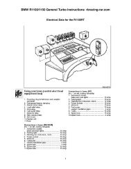
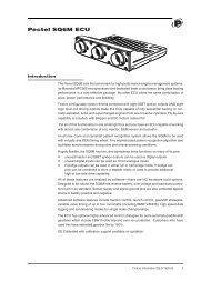
SENSATA TECHNOLOGIESCharacteristicsArc Fault1.200MAX5 AMP RATING SHOWN515/32ø .3951.2191.3121.030 MAX.284.704NEUTRAL LEAD LENGTH& CONNECTION TBD.800 MAXCalibration: 1-25 ampsTEMPo C+25-54+121MIN ULTTRIP115%115%85%MAX ULTTRIP138%165%145%TRIP TIME - SECONDS200%4-167-352-13500%.4-1.6.6-3.0.25-1.0Vibration*....................... 10 G’s minimum, 50 - 500 HzMechanical Shock.......... 50 G’sAcceleration................... 10 G’sWeight............................ 42 gm maxInterrupt Current1-20 amps: 6000 amps at 28 VDC25 amps: 1625 amps at 28 VDC1-15 amps: 2500 amps at 120 VAC, 400 Hz20 amps: 2000 amps at 120 VAC, 400 Hz25 amps: 1800 amps at 120 VAC, 400 HzEndurance2500 cycles 120 VAC, 400 Hz Inductive5000 cycles 120 VAC, 400 Hz Resistive2500 cycles 30 VDC Inductive5000 cycles 30 VDC Resistive10,000 cycles Mechanical, no load* Other vibration levels available. Contact factory for details.1000%.10-.40.15-.70.06-.25Performance:Discrimination (resistance to nuisance trips)Devices manufactured by <strong>Sensata</strong> have demonstrated successon start up, bus transfer, and shut down for motor, fan,strobe light, and fluorescent light.Detail performance per test document 76508Phase to Phase and Phase to Ground 400 Hz, 120/205VACGuillotine Arc Test:Guillotine Arc Current .......Less than 700% RC rmsSteady State Load ..............None to rated currentMaximum Arcing Cycles ....EightArcing Time Duration .........Less than 100msLoose Terminal Arc DetectionSteady State Load ..............Less than 40% RC rmsTripping Time: ....................Less than 2 minutesVibration Source .................Eccentric motor vibratory tableWet Arc DetectionMIL-STD-2223 Method 3005, wire per MIL-W-81381/111000Approximate Time-Current Curves – APD <strong>Circuit</strong> <strong>Breakers</strong>-54 o C MAXIMUM TRIP CURVE% Rated Current100+121 o C MINIMUM TRIP CURVE+25 o C TRIP BAND165%138%115%85%0.01 0.1 1 10 100 1000Trip Time in Seconds
Cross ReferenceQPL approved <strong>Aircraft</strong> <strong>Circuit</strong> <strong>Breakers</strong> specifications have been or are in the process of being converted to SAEindustry standard. The specification requirements and part marking remains as per the original military slashsheet. The only difference is the SAE industry designation for the military slash sheet.AS Number<strong>Sensata</strong> NumberAS Number<strong>Sensata</strong> NumberAS Number<strong>Sensata</strong> NumberAS 33201AS 33201LAS 33201VAS 14105AS 14105LAS 14153AS 14154AS 14154L2TC22TC272TC633TC23TC279TC26TC26TC37AS 14154VAS 22073AS 22073VAS 26574AS 25244AS 25244(P)6TC637274-117274-697274-23TC73TC8AS 26574AAS 26574LAS 24509AAS 24509BAS 24510AAS 24510B7274-47274-707270-17270-77271-87271-3Commercial <strong>Aircraft</strong> <strong>Circuit</strong> Breaker Cross ReferenceBoeing Basic Specification<strong>Sensata</strong>StyleAirbus Basic Specification<strong>Sensata</strong>StyleLockheed Basic Specification<strong>Sensata</strong>StyleBACC18UBACC18WBACC18ZBACC18AABACC18ACBACC18ADBACC18AE10-60806-XX10-60806-XXXXBoeing (DPD)5D0001NoneNone7274-217276-132TC62TC146TC62TC479TC66752-3046752-3117274-627274-557276-115NSA931303NSA931304NSA931320NSA931321NSA931322NSA931323NSA931324NSA931325E0730-005E0731-005E0732-005E0733-0056752-126752-3052TC505TC506TC5015TC502TC646TC642TC656TC655TC6515TC65LS10158LS10159S2TC20, 3TC202TC26/3TC266TC20, 9TC206TC26/9TC26For FAA/PMA part availability go to www.sensata.comEuropean NormsEN2495EN2592EN2794EN2995EN2996EN3661EN3662EN3773EN3774
Simplified Glossary of <strong>Circuit</strong> Breaker Terms<strong>Circuit</strong> breaker– A devicedesigned to carry a specific valueof current and automatically opena circuit upon overloads orshort circuits.Thermal circuit breaker –A circuit breaker that senses acurrent overload based on thermalheating of the sensing element.Time-current curve – An approximategraph showing the minimumand maximum time a specificbreaker will take to trip on variousdegrees of overload.Ambient compensation –A feature of some thermal breakersthat limits or eliminates thermalderating due to ambienttemperature.Minimum ultimate trip – Currentrating at which a breaker will nottrip within a certain period (usually1 hour) at a specified temperature.Maximum ultimate trip – Currentrating at which a breaker must tripwithin a certain period (usually 1hour) at a specified temperature.Thermal derating – Tendency of abreaker to trip at lower currentlevels due to higher ambienttemperatures, and to trip at higherlevels due to lower ambienttemperatures.Trip-free – Feature of certainbreakers that makes it impossible tohold the breaker closed against anoverload.Manual reset – Method ofaccomplishing reclosure aftercircuit interruption has occurred.Indicating, non-indicating –Whether or not breaker givesprominent visual indication ofopening, such as exposing a whiteband around button, or movingtoggle to off position.Manual trip – Ability of breakerto be opened manually.Auxiliary circuit – An integrallyhoused, electrically independentswitch linked mechanically tooperate with the main circuitbreaker contacts.Voltage drop – The voltagedecrease across the breaker due tointernal resistance of the device.WARRANTY<strong>Sensata</strong> Technologies warrants its circuit breakersagainst faulty workmanship or the use ofdefective materials for a period of 18 monthsfrom date of manufacture. This warrantyapplies only to products purchased directlyfrom <strong>Sensata</strong> Technologies or through an authorized<strong>Sensata</strong> Technologies distributor. During thewarranty period, any circuit breaker found by<strong>Sensata</strong> Technologies, in its sole judgement, to bedefective, will be repaired or replaced, at theoption of <strong>Sensata</strong> Technologies. Under no circumstancesdoes <strong>Sensata</strong> Technologies responsibilityor liability extend to incidental or consequentialdamages whatsoever.The foregoing is in lieu of all warrantiesexpress, implied or statutory, including, but notlimited to, any implied warranty of merchantabilityand fitness for a purpose and of anyother warranty obligation on the part of<strong>Sensata</strong> Technologies.Important Notice: <strong>Sensata</strong> Technologies (<strong>Sensata</strong>) reserves the right to make changes to or discontinue any product orservice identified in this publication without notice. <strong>Sensata</strong> advises its customers to obtain the latest version of the relevantinformation to verify, before placing any orders, that the information being relied upon is current. <strong>Sensata</strong> assumes no responsibilityfor infringement of patents or rights of others based on <strong>Sensata</strong> applications assistance or product specificationssince <strong>Sensata</strong> does not possess full access concerning the use or application of customers’ products. <strong>Sensata</strong> also assumesno responsibility for customers’ product designs.
KansasNew YorkAuthorized DistributorsUnited KingdomHollandFranceCaliforniaGeorgiaIsraelItalySingaporeAuthorized U.S. Distributors of All <strong>Products</strong>NameMain OfficePhoneFaxWeb SitePeerless ElectronicsFlame EnterprisesTPS AviationLynbrook, NYCanoga Park, CAHayward, CA(800) 285-2121(516) 593-2121(800) 854-2255(818) 700-2905(510) 475-1010(516) 593-2179(818) 700-9168(510) 475-8817www.peerlesselectronics.comwww.flamecorp.comAvio DiepenAtlanta, GA(770) 996-6430(770) 996-8430www.avio-diepen.comWesco <strong>Aircraft</strong>Wichita, KS(800) 544-4070www.airtechnics.comOther Distributors and Sales AgentsNameMain OfficePhoneFaxWeb SiteJB ControlsAvio DiepenCharcroft Electronics LtdOdem ElectronicsPatton Air<strong>Precision</strong> TechnologiesParis, FranceHollandEnglandIsraelItalySingapore33 1 56 47 04 0431 172 449759+44 (0) 1591 610408972 3 966 034039 331 792 6586 65 27 34 57333 1 56 47 04 0531 172 449789972 3 966 034539 331 796 5526 65 27 38 898jboher@jbcontrols.comavio-diepen@avio-diepen.comsales@charcroft.comwww.odem.co.ilprovest@logic.itpretech@singnet.com.sgwww.sensata.com