P.00-15 - Outlander-Forum
P.00-15 - Outlander-Forum
P.00-15 - Outlander-Forum

Create successful ePaper yourself
Turn your PDF publications into a flip-book with our unique Google optimized e-Paper software.
00-1<br />
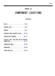
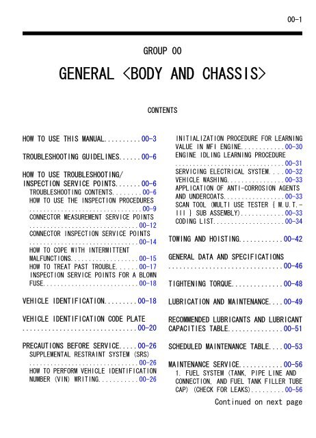
GROUP 00<br />
GENERAL <br />
CONTENTS<br />
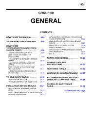
HOW TO USE THIS MANUAL..........00-3<br />
TROUBLESHOOTING GUIDELINES......00-6<br />
HOW TO USE TROUBLESHOOTING/<br />
INSPECTION SERVICE POINTS.......00-6<br />
TROUBLESHOOTING CONTENTS........00-6<br />
HOW TO USE THE INSPECTION PROCEDURES<br />
................................00-9<br />
CONNECTOR MEASUREMENT SERVICE POINTS<br />
...............................00-12<br />
CONNECTOR INSPECTION SERVICE POINTS<br />
...............................00-14<br />
HOW TO COPE WITH INTERMITTENT<br />
MALFUNCTIONS...................00-<strong>15</strong><br />
HOW TO TREAT PAST TROUBLE......00-17<br />
INSPECTION SERVICE POINTS FOR A BLOWN<br />
FUSE...........................00-18<br />
VEHICLE IDENTIFICATION.........00-18<br />
VEHICLE IDENTIFICATION CODE PLATE<br />
...............................00-20<br />
PRECAUTIONS BEFORE SERVICE.....00-26<br />
SUPPLEMENTAL RESTRAINT SYSTEM (SRS)<br />
...............................00-26<br />
HOW TO PERFORM VEHICLE IDENTIFICATION<br />
NUMBER (VIN) WRITING...........00-26<br />
INITIALIZATION PROCEDURE FOR LEARNING<br />
VALUE IN MFI ENGINE............00-30<br />
ENGINE IDLING LEARNING PROCEDURE<br />
...............................00-31<br />
SERVICING ELECTRICAL SYSTEM....00-32<br />
VEHICLE WASHING................00-33<br />
APPLICATION OF ANTI-CORROSION AGENTS<br />
AND UNDERCOATS.................00-33<br />
SCAN TOOL (MULTI USE TESTER { M.U.T.-<br />
III } SUB ASSEMBLY)............00-33<br />
CODING LIST....................00-34<br />
TOWING AND HOISTING............00-42<br />
GENERAL DATA AND SPECIFICATIONS<br />
...............................00-46<br />
TIGHTENING TORQUE..............00-48<br />
LUBRICATION AND MAINTENANCE....00-49<br />
RECOMMENDED LUBRICANTS AND LUBRICANT<br />
CAPACITIES TABLE...............00-51<br />
SCHEDULED MAINTENANCE TABLE....00-53<br />
MAINTENANCE SERVICE............00-56<br />
1. FUEL SYSTEM (TANK, PIPE LINE AND<br />
CONNECTION, AND FUEL TANK FILLER TUBE<br />
CAP) (CHECK FOR LEAKS).........00-56<br />
Continued on next page
00-2<br />
2. FUEL HOSES (CHECK CONDITION)<br />
...............................00-56<br />
3. AIR CLEANER ELEMENT (REPLACE)<br />
...............................00-56<br />
4. EVAPORATIVE EMISSION SYSTEM<br />
(EXCEPT EVAPORATIVE EMISSION<br />
CANISTER) (CHECK FOR CLOGGING)<br />
...............................00-57<br />
5. SPARK PLUGS (REPLACE).......00-57<br />
6. INTAKE AND EXHAUST VALVE CLEARANCE<br />
(INSPECT AND<br />
ADJUST)........................00-57<br />
7. TIMING BELT (REPLACE).......00-58<br />
8. DRIVE BELT (FOR GENERATOR, WATER<br />
PUMP, POWER STEERING OIL PUMP) (CHECK<br />
CONDITION).....................00-58<br />
9. EXHAUST SYSTEM (CONNECTIONS<br />
PORTION OF MUFFLER, MUFFLER PIPES AND<br />
CONVERTER HEAT SHIELDS) (CHECK AND<br />
SERVICE AS REQUIRED)...........00-61<br />
10. ENGINE OIL (CHANGE)........00-62<br />
11. ENGINE OIL FILTER (REPLACE)<br />
...............................00-63<br />
12. TRANSMISSION FLUID.........00-64<br />
13. TRANSFER OIL...............00-67<br />
14. ENGINE COOLANT (CHANGE)....00-67<br />
<strong>15</strong>. COOLANT HOSES (RADIATOR HOSE,<br />
HEATER HOSE) (INSPECT).........00-69<br />
16. DISC BRAKE PADS (INSPECT FOR WEAR)<br />
...............................00-69<br />
17. BRAKE HOSES (CHECK FOR<br />
DETERIORATION OR LEAKS)........00-69<br />
18. BALL JOINT AND STEERING LINKAGE<br />
SEALS (INSPECT FOR GREASE LEAKS AND<br />
DAMAGE)........................00-69<br />
19. DRIVE SHAFT BOOTS (INSPECT FOR<br />
GREASE LEAKS AND DAMAGE).......00-70<br />
20. SUSPENSION SYSTEM (INSPECT FOR<br />
LOOSENESS AND DAMAGE)..........00-70<br />
21. REAR AXLE OIL (CHECK OIL LEVEL)<br />
...............................00-70<br />
22. TIRES (ROTATE).............00-71<br />
23. AIR FILTER (REPLACE).......00-71<br />
MAIN SEALANT AND ADHESIVE TABLE<br />
...............................00-71
GENERAL <br />
HOW TO USE THIS MANUAL<br />
00-3<br />
HOW TO USE THIS MANUAL<br />
MAINTENANCE, REPAIR AND SERVICING<br />
EXPLANATIONS<br />
This manual provides explanations, etc. concerning<br />
procedures for the inspection, maintenance, repair<br />
and servicing of the subject model. Unless otherwise<br />
specified, each service procedure covers all models.<br />
Procedures covering specific models are identified by<br />
the model codes, or similar designation (engine type,<br />
transaxle type, etc.). A description of these<br />
designations is covered in this manual under<br />
"VEHICLE IDENTIFICATION."<br />
ON-VEHICLE SERVICE<br />
The "ON-VEHICLE SERVICE" section has<br />
procedures for performing inspections and<br />
adjustments of particularly important components.<br />
These procedures are done with regard to<br />
maintenance and servicing, but other inspections<br />
(looseness, play, cracking, damage, etc.) must also<br />
be performed.<br />
SERVICE PROCEDURES<br />
The service steps are arranged in numerical order.<br />
Attention to be paid in performing vehicle service are<br />
described in detail in SERVICE POINTS.<br />
DEFINITION OF TERMS<br />
STANDARD VALUE<br />
Indicates the value used as the standard for judging<br />
whether or not a part or adjustment is correct.<br />
LIMIT<br />
Shows the maximum or minimum value for judging<br />
whether or not a part or adjustment is acceptable.<br />
REFERENCE VALUE<br />
Indicates the adjustment value prior to starting the<br />
work (presented in order to facilitate assembly and<br />
adjustment procedures, and so they can be<br />
completed in a shorter time).<br />
M10001000001USA0000010001<br />
DANGER, WARNING, AND CAUTION<br />
DANGER, WARNING, and CAUTION call special<br />
attention to a necessary action or to an action that<br />
must be avoided. The differences among DANGER,<br />
WARNING, and CAUTION are as follows:<br />
⦆If a DANGER is not followed, the result is severe<br />
bodily harm or even death.<br />
⦆If a WARNING is not followed, the result could be<br />
bodily injury.<br />
⦆If a CAUTION is not followed, the result could be<br />
damage to the vehicle, vehicle components or<br />
service equipment.<br />
TIGHTENING TORQUE INDICATION<br />
The tightening torque indicates a median and its<br />
tolerance by a unit of N·m (in-lb) or N·m (ft-lb). For<br />
fasteners with no assigned torque value, refer to P.<br />
00-48.<br />
SPECIAL TOOL NOTE<br />
Only MMC special tool part numbers are called out in<br />
the repair sections of this manual. Please refer to the<br />
special tool cross-reference chart located at the<br />
beginning of each group, for the special tool number<br />
that is available in your market.<br />
ABBREVIATIONS<br />
The following abbreviations are used in this manual<br />
for classification of model types:<br />
NOTE:<br />
⦆A/T: Automatic transaxle, or models equipped with<br />
automatic transaxle.<br />
⦆MFI: Multiport fuel injection, or engines equipped<br />
with multiport fuel injection.<br />
⦆FWD: 2-wheel drive vehicles.<br />
⦆AWD: 4-wheel drive vehicles.<br />
⦆A/C: Air conditioning.<br />
⦆3.0L Engine: 2.998 liter 6B31 engine, or a model<br />
equipped with such an engine.<br />
⦆PCM: Powertrain control module<br />
⦆SWS: Simplified wiring system<br />
⦆Keyless Operation System (KOS): Free-hand<br />
Advanced Security Transmitter (F.A.S.T.-key)
00-4<br />
GENERAL <br />
HOW TO USE THIS MANUAL<br />
EXPLANATION OF MANUAL CONTENTS<br />
Denotes tightening torque.<br />
If there is no indication of<br />
tightening torque, refer to<br />
tightening torque.<br />
Indicates the<br />
section title.<br />
Indicates the<br />
group title.<br />
Indicates the<br />
group number.<br />
Indicates the page number.<br />
Indicates procedures to be performed before<br />
the work in that section is started, and<br />
procedures to be performed after the work<br />
in that section is finished.<br />
Mark N<br />
denotes non-reusable part.<br />
Component diagram<br />
A diagram of the component parts is provided<br />
near the front of each section in order<br />
to give the reader a better understanding of<br />
the installed condition of component parts.<br />
Repair kit or parts sets are shown.<br />
(Only very frequently used parts are shown.)<br />
Brake caliper kit Pad set Shim kit Seal and boot kit<br />
Maintenance and servicing procedures<br />
The numbers provided within the diagram indicate the<br />
sequence for maintenance and servicing procedures.<br />
Removal steps :<br />
The part designation number corresponds to<br />
the number in the illustration to indicate removal<br />
steps.<br />
Disassembly steps :<br />
The part designation number corresponds to<br />
the number in the illustration to indicate disassembly<br />
steps.<br />
Installation steps :<br />
Specified in case installation is impossible in<br />
reverse order of removal steps. Omitted if<br />
installation is possible in reverse order of<br />
removal steps.<br />
Assembly steps :<br />
Specified in case installation is impossible in<br />
reverse order of removal steps. Omitted if<br />
assembly is possible in reverse order of<br />
disassembly steps.<br />
ZC6012870000
GENERAL <br />
HOW TO USE THIS MANUAL<br />
00-5<br />
Classifications of major maintenance / service points<br />
When there are major points relative to maintenance and servicing procedures (such as essential maintenance<br />
and service points, maintenance and service standard values, information regarding the use of special tools, etc.).<br />
These are arranged together as major maintenance and service points and explained in detail.<br />
: Indicates that there are essential points for removal or disassembly.<br />
>>A
00-6<br />
GENERAL <br />
TROUBLESHOOTING GUIDELINES<br />
TROUBLESHOOTING GUIDELINES<br />
VERIFY THE COMPLAINT<br />
⦆Make sure the customer's complaint and the service<br />
writer's work order description are understood<br />
before starting work.<br />
⦆Make sure the correct operation of the system is<br />
understood. Read the service manual description to<br />
verify normal system operation.<br />
⦆Operate the system to see the symptoms. Look for<br />
other symptoms that were not reported by the<br />
customer, or on the work order, that may be related<br />
to the problem.<br />
DETERMINE POSSIBLE CAUSES<br />
Compare the confirmed symptoms to the diagnostic<br />
symptom indexes to find the right diagnosis<br />
procedure.<br />
If the confirmed symptoms cannot be found on any<br />
symptom index, determine other possible causes.<br />
⦆Analyze the system diagrams and list all possible<br />
causes for the problem symptoms.<br />
⦆Rank all these possible causes in order of<br />
probability, based on how much of the system they<br />
cover, how likely they are to be the cause, and how<br />
easy they will be to check. Be sure to take<br />
experience into account. Consider the causes of<br />
similar problems seen in the past. The list of causes<br />
should be ranked in order from general to specific,<br />
from most-likely to least-likely, and from easy-tocheck<br />
to hard-to-check.<br />
FIND THE PROBLEM<br />
After the symptoms have been confirmed, and<br />
probable causes have been identified, the next step<br />
M10001000088USA0000010001<br />
is to make step-by-step checks of the suspected<br />
system components, junctions, and links in logical<br />
order.<br />
Use the diagnostic procedures in the service manual<br />
whenever possible. Follow these procedures carefully<br />
to avoid missing an important step in the diagnosis<br />
sequence. It might be the skipped step that leads to<br />
the solution of the problem.<br />
If the service manual doesn't have step-by-step<br />
procedures to help diagnose the problem, make a<br />
series of checks based on the ranked list of probable<br />
causes. Troubleshooting checks should be made in<br />
the order that the list of causes was ranked:<br />
⦆general to specific<br />
⦆most-likely to least-likely<br />
⦆easy-to-check to hard-to-check<br />
REPAIR THE PROBLEM<br />
When the step-by-step troubleshooting checks find a<br />
fault, perform the proper repairs. Make sure to fix the<br />
root cause of the problem, not just the symptom. Just<br />
fixing the symptom, without fixing the root cause, will<br />
cause the symptom to eventually return.<br />
VERIFY THE REPAIR<br />
After repairs are made, recheck the operation of the<br />
system to confirm that the problem is eliminated. Be<br />
sure to check the system thoroughly. Sometimes new<br />
problems are revealed after repairs have been made.<br />
HOW TO USE TROUBLESHOOTING/INSPECTION SERVICE POINTS<br />
TROUBLESHOOTING CONTENTS<br />
M10001000133USA0000010001<br />
The SRS-ECU adopts the rollover specification<br />
that the curtain airbag and seat belt pre-tensioner<br />
operate at the occurrence of rollover. Therefore,<br />
do not tilt the vehicle to the right and left with the<br />
IG ON or tilt the SRS-ECU to the right and left with<br />
the IG ON and the harness installed.<br />
During diagnosis, a diagnostic trouble code<br />
associated with other system may be set when the
GENERAL <br />
HOW TO USE TROUBLESHOOTING/INSPECTION SERVICE POINTS<br />
00-7<br />
ignition switch is turned "ON" with connector(s)<br />
disconnected. On completion, confirm all<br />
systems for diagnostic trouble code(s). If<br />
diagnostic trouble code(s) are set, erase them all.<br />
Since the radiator fan rotates during CAN bus line<br />
diagnostics, make sure that no one is servicing<br />
the engine compartment before diagnosing the<br />
CAN bus line. Since the CAN communication<br />
stops when diagnosing the CAN bus line, the<br />
ETACS-ECU detects the time-out of the engine<br />
control module, and activates the radiator fan to<br />
prevent overheating as fail-safe.<br />
Troubleshooting of electronic control systems for<br />
which scan tool MB991958 can be used follows the<br />
basic outline described below. Even in systems for<br />
which scan tool MB991958 cannot be used, some of<br />
these systems still follow this outline.<br />
1. STANDARD FLOW OF DIAGNOSTIC TROUBLESHOOTING<br />
Troubleshooting sections are based on the diagnostic required, the details of such differences or additions<br />
flow as below. If the diagnostic flow is different from will also be listed.<br />
that given below, or if additional explanation is<br />
Diagnostic method<br />
Gathering information<br />
from the customer.<br />
Reoccurs<br />
Check trouble symptom.<br />
Does not reoccur<br />
CAN bus diagnosis*<br />
1<br />
NG<br />
CAN bus diagnosis chart*<br />
2<br />
OK<br />
Read the diagnosis code.<br />
Diagnosis code<br />
displayed.<br />
(Current trouble)*<br />
3<br />
Diagnosis code<br />
displayed.<br />
(Current trouble)*<br />
3<br />
Read the diagnosis code.<br />
No diagnosis<br />
code or<br />
communication<br />
with scan tool<br />
MB991958 not<br />
possible<br />
Diagnosis code<br />
displayed.<br />
(Past trouble)*<br />
How to treat past<br />
4<br />
trouble*<br />
After taking note of the<br />
malfunction code, erase the<br />
diagnosis code memory.<br />
Recheck trouble symptom.<br />
Diagnosis code<br />
displayed.<br />
(Past trouble)*<br />
How to treat past<br />
4<br />
trouble*<br />
No diagnosis<br />
code.<br />
Read the diagnosis codes.<br />
Diagnosis code<br />
displayed.<br />
Coding data check* 6 0000<br />
3 3<br />
No diagnosis<br />
code.<br />
Refer to the INSPECTION CHA<br />
FOR T ROUBLE SYMP TOMS<br />
(Refer to applica ble group) .<br />
RT<br />
Refer to the INSPECTION CHA<br />
FOR DI AGNOSIS CODES<br />
(Refer to applica ble group) .<br />
RT<br />
INTERMITTENT MALFUNCTIONS *<br />
5<br />
ZC604018<br />
⦆ * 1 : For how to diagnose CAN bus lines, refer to<br />
GROUP 54D P.54D-10.<br />
⦆ * 2 : For the CAN bus diagnosis chart, refer to<br />
GROUP 54D P.54D-17.
00-8<br />
GENERAL <br />
HOW TO USE TROUBLESHOOTING/INSPECTION SERVICE POINTS<br />
⦆ * 3 : When scan tool MB991958 detects a diagnostic<br />
trouble code, its display informs users whether a<br />
mechanical problem currently exists or whether it<br />
existed before. The message for the former state<br />
identifies it as an "Active" and the message for the<br />
latter identifies it as a "Stored".<br />
⦆ * 4 : For how to treat past trouble, refer to P.<br />
00-17.<br />
⦆ * 5 : For how to cope with intermittent malfunctions,<br />
refer to <strong>P.00</strong>-<strong>15</strong>.<br />
⦆ * 6 : For coding data, refer to <strong>P.00</strong>-34.<br />
2. SYSTEM OPERATION AND SYMPTOM<br />
VERIFICATION TESTS<br />
If verification of the symptom(s) is difficult, procedures<br />
for checking operation and verifying symptoms are<br />
shown.<br />
3. DIAGNOSTIC FUNCTION<br />
The following trouble code diagnosis are shown.<br />
⦆How to read diagnostic trouble codes<br />
⦆How to erase diagnostic trouble codes<br />
⦆Input inspection service points<br />
4. DIAGNOSTIC TROUBLE CODE CHART<br />
If the scan tool displays a diagnostic trouble code, find<br />
the applicable inspection procedure according to this<br />
chart.<br />
5. SYMPTOM CHART<br />
If there are symptoms, even though the scan tools<br />
show that no DTCs are set, inspection procedures for<br />
each symptom will be found by using this chart.<br />
6. DIAGNOSTIC TROUBLE CODE<br />
PROCEDURES<br />
Indicates the inspection procedures corresponding to<br />
each diagnostic trouble code. (Refer to <strong>P.00</strong>-9).<br />
7. SYMPTOM PROCEDURES<br />
Indicates the inspection procedures corresponding to<br />
each symptom listed in the Symptom Chart. (Refer<br />
to <strong>P.00</strong>-9).<br />
8. SERVICE DATA REFERENCE TABLE<br />
Inspection items and normal judgment values have<br />
been provided in this chart as reference information.<br />
9. CHECK AT ECU TERMINALS<br />
Terminal numbers for the ECU connectors, inspection<br />
items, and standard values have been provided in this<br />
chart as reference information.<br />
1.Connect a needle-nosed wire probe to a voltmeter<br />
probe.<br />
Short-circuiting the positive (+) probe between a<br />
connector terminal and ground could damage the<br />
vehicle wiring, the sensor, the ECU, or all three.<br />
Use care to prevent this!<br />
2.Insert the needle-nosed wire probe into each of the<br />
ECU connector terminals from the wire side, and<br />
measure the voltage while referring to the check<br />
chart.<br />
NOTE: Measure voltage with the ECU connectors<br />
connected.You may find it convenient to pull out<br />
the ECU to make it easier to reach the connector<br />
terminals.Checks don't have to be carried out in<br />
the order given in the chart.<br />
3.If voltage readings differ from normal condition<br />
values, check related sensors, actuators, and<br />
wiring. Replace or repair as needed.<br />
4.After repair or replacement, recheck with the<br />
voltmeter to confirm that the repair has corrected<br />
the problem.<br />
TERMINAL RESISTANCE AND CONTINUITY<br />
CHECKS<br />
1.Turn the ignition switch to the "LOCK" (OFF)<br />
position.<br />
2.Disconnect the ECU connector.<br />
If resistance and continuity checks are performed<br />
on the wrong terminals, damage to the vehicle<br />
wiring, sensors, ECU, and/or ohmmeter may<br />
occur. Use care to prevent this!<br />
3.Measure the resistance and check for continuity<br />
between the terminals of the ECU harness-side<br />
connector while referring to the check chart.<br />
NOTE: Checks don't have to be carried out in<br />
the order given in the chart.<br />
4.If the ohmmeter shows any deviation from the<br />
Normal Condition value, check the corresponding<br />
sensor, actuator and related electrical wiring, then<br />
repair or replace.<br />
5.After repair or replacement, recheck with the<br />
ohmmeter to confirm that the repair has corrected<br />
the problem.<br />
TERMINAL VOLTAGE CHECKS
GENERAL <br />
HOW TO USE TROUBLESHOOTING/INSPECTION SERVICE POINTS<br />
00-9<br />
10. INSPECTION PROCEDURES USING<br />
AN OSCILLOSCOPE<br />
When there are inspection procedures using an<br />
oscilloscope, these are listed.<br />
HOW TO USE THE INSPECTION PROCEDURES<br />
The causes of many of the problems occurring in<br />
electric circuitry are generally the connectors,<br />
components, the ECU, and the harnesses between<br />
M10001000135USA0000010001<br />
connectors, in that order. These inspection<br />
procedures follow this order. They first try to discover<br />
a problem with a connector or a defective component.
00-10<br />
GENERAL <br />
HOW TO USE TROUBLESHOOTING/INSPECTION SERVICE POINTS<br />
(1) Relevant circuit(s) of the component which<br />
the DTC indicates are described.<br />
Connector : B-4 8<br />
Inta ke air<br />
tempe rature<br />
sensor<br />
(2) For connector color, refer to GROUP 80A,<br />
How to read configuration diagrams.<br />
(3) Shows the location of the connector(s) from<br />
the circuit(s) above.<br />
B-48(B)<br />
(4) Explains about the operation principle of the<br />
component or its relevant parts in that circuit.<br />
ZC6012890000
GENERAL <br />
HOW TO USE TROUBLESHOOTING/INSPECTION SERVICE POINTS<br />
00-11<br />
(5) Explains about technical details. (6) Describes the conditions for that DTC<br />
being set (stored).<br />
(7) Describes possible<br />
cause(s)for that DTC.<br />
(8) Start of the diagnosis procedure<br />
for that DTC.<br />
(M. U.T.-III Sub Assem<br />
bly)<br />
(9) Identifies the special tool(s)<br />
necessary for diagnosing that DTC.<br />
Data link<br />
connector<br />
(10) Provides the inspection procedure<br />
for that DTC step by step.<br />
ZC6012900000<br />
HARNESS INSPECTION<br />
Check for an open or short circuit in the harness<br />
between the terminals which were faulty according to<br />
the connector measurements. Carry out this<br />
inspection while referring to GROUP 00E, Harness<br />
Connector Inspection <strong>P.00</strong>E-2. Here, "Check<br />
harness between power supply and terminal xx" also<br />
includes checking for blown fuse. For inspection<br />
service points when there is a blown fuse, refer to<br />
"Inspection Service Points for a Blown Fuse P.<br />
00-18."<br />
MEASURES TO TAKE AFTER REPLACING<br />
THE ECU<br />
If the trouble symptoms have not disappeared even<br />
after replacing the ECU, repeat the inspection<br />
procedure from the beginning.
00-12<br />
GENERAL <br />
HOW TO USE TROUBLESHOOTING/INSPECTION SERVICE POINTS<br />
CONNECTOR MEASUREMENT SERVICE POINTS<br />
M10001000136USA0000010001<br />
Turn the ignition switch to the "LOCK" (OFF) position when<br />
connecting and disconnecting the connectors. Turn the ignition<br />
switch to "ON" when measuring, unless there are instructions to<br />
the contrary.<br />
Special tool<br />
IF INSPECTING WITH THE CONNECTOR<br />
CONNECTED WATERPROOF CONNECTORS<br />
Be sure to use special tool. Never insert a test probe from the<br />
harness side, as this will reduce the waterproof performance and<br />
result in corrosion.<br />
ZC5018920000<br />
MB992006<br />
IF INSPECTING WITH THE CONNECTOR<br />
CONNECTED ORDINARY (NON-WATERPROOF)<br />
CONNECTORS<br />
Required Special Tool:<br />
⦆MB992006: Extra Fine Probe<br />
Inspect by inserting a test probe from the harness side. If the<br />
connector is too small to insert a test probe (e.g. control unit<br />
connector), do not insert it forcibly. Use special tool MB992006<br />
(extra fine probe).<br />
ZC5018930000<br />
MB991219<br />
ZC5019070000<br />
IF INSPECTING WITH THE CONNECTOR<br />
DISCONNECTED<br />
When Inspecting a Female Pin<br />
⦆From front side of the connector<br />
Required Special Tool:<br />
MB991219: Inspection Harness (Included in MB991223,<br />
Harness Set)<br />
The inspection harness for connector pin contact<br />
pressure should be used. The test probe should never be<br />
forcibly inserted, as it may cause a defective contact.<br />
⦆From back side of the connector (SRS-ECU harness side<br />
connector)
GENERAL <br />
HOW TO USE TROUBLESHOOTING/INSPECTION SERVICE POINTS<br />
00-13<br />
SRS-ECU harness<br />
connector<br />
Since the SRS-ECU harness connector is plated to<br />
improve conductivity, observe the warning below when<br />
checking this connector.<br />
ZC5019080000<br />
Insert the backprobing tool into the connector from<br />
the harness side, and connect the tester to the<br />
backprobing tool. If any tool other than the<br />
backprobing tool is used, it may cause damage to the<br />
harness and other components. Furthermore,<br />
measurement should not be carried out by touching<br />
the backprobing tool directly against the terminals<br />
from the front of the connector. The terminals are<br />
plated to increase their conductivity, so that if they<br />
are touched directly by the backprobing tool, the<br />
plating may break, which will decrease reliability.<br />
When Inspecting a Male Pin<br />
At this time, be careful not to short the connector pins<br />
with the test probes. Doing so may damage the circuits<br />
inside the ECU.<br />
Touch the pin directly with the test probe.<br />
ZC5019090000
00-14<br />
GENERAL <br />
HOW TO USE TROUBLESHOOTING/INSPECTION SERVICE POINTS<br />
CONNECTOR INSPECTION SERVICE POINTS<br />
M10001000137USA0000010001<br />
VISUAL INSPECTION<br />
⦆<br />
Connector disconnected or<br />
improperly connected<br />
Stretched or broken wires<br />
Harness wire breakage<br />
at terminal section<br />
Low contact<br />
pressure<br />
Good<br />
Bad<br />
ZC5019100000<br />
Connector is disconnected or improperly connected<br />
⦆Connector pins are pulled out<br />
⦆Stretched an broken wires at terminal section<br />
⦆Low contact pressure between male and female terminals<br />
⦆Low connection pressure due to rusted terminals or foreign<br />
matter lodged in terminals
GENERAL <br />
HOW TO USE TROUBLESHOOTING/INSPECTION SERVICE POINTS<br />
00-<strong>15</strong><br />
CONNECTOR PIN INSPECTION<br />
If the connector pin stopper is damaged, the terminal<br />
connections (male and female pins) will not be perfect even<br />
when the connector body is connected, because the pins may<br />
pull out of the back side of the connector. Therefore, gently pull<br />
the wires one by one to make sure that no pins pull out of the<br />
connector.<br />
ZC5019110000<br />
MB991219<br />
CONNECTOR ENGAGEMENT INSPECTION<br />
Required Special Tool:<br />
MB991219: Inspection Harness (contained in MB991223 Test<br />
Harness)<br />
Use special tool, MB991219 to inspect the engagement of the<br />
male pins and female pins. [Pin drawing force: 1 N (0.2 pound)<br />
or more]<br />
ZC5019160000<br />
HOW TO COPE WITH INTERMITTENT<br />
MALFUNCTIONS<br />
M10001000139USA0000010000<br />
Most intermittent malfunctions occur under certain conditions. If<br />
those conditions can be identified, the cause will be easier to<br />
find.<br />
TO COPE WITH INTERMITTENT MALFUNCTION;<br />
1. ASK THE CUSTOMER ABOUT THE MALFUNCTION<br />
Ask what it feels like, what it sounds like, etc. Then ask about<br />
driving conditions, weather, frequency of occurrence, and so on.<br />
2. DETERMINE THE CONDITIONS FROM THE CUSTOMER'S<br />
RESPONSES<br />
Typically, almost all intermittent malfunctions occur from<br />
conditions like vibration, temperature and/or moisture change,<br />
poor connections. From the customer's responses, it should be<br />
reasoned which condition is most likely.
00-16<br />
GENERAL <br />
HOW TO USE TROUBLESHOOTING/INSPECTION SERVICE POINTS<br />
3. USE SIMULATION TEST<br />
Use the simulation tests below to attempt to duplicate the<br />
customer's complaint. Determine the most likely circuit(s) and<br />
perform the simulation tests on the connectors and parts of that<br />
circuit(s). Be sure to use the inspection procedures provided for<br />
diagnostic trouble codes and trouble symptoms.<br />
For temperature and/or moisture condition related intermittent<br />
malfunctions, try to change the conditions of the suspected<br />
circuit components, then use the simulation tests below.<br />
4. VERIFY THE INTERMITTENT MALFUNCTION IS<br />
ELIMINATED<br />
Repair the malfunctioning part and try to duplicate the condition<br />
(s) again to verify the intermittent malfunction has been<br />
eliminated.<br />
SIMULATION TESTS<br />
NOTE: In case of difficulty in finding the cause of the<br />
intermittent malfunction, the data recorder function in the<br />
scan tool is effective.
GENERAL <br />
HOW TO USE TROUBLESHOOTING/INSPECTION SERVICE POINTS<br />
00-17<br />
For these simulation tests, shake, then gently bend, pull, and<br />
twist the wiring of each of these examples to duplicate the<br />
intermittent malfunction.<br />
⦆Shake the connector up-and-down, and right-and-left.<br />
⦆Shake the wiring harness up-and-down, and right-and-left.<br />
Especially, check the splice points of wiring harnesses<br />
carefully. Refer to GROUP 00E, Harness Connector<br />
Inspection <strong>P.00</strong>E-2.<br />
⦆Shake the part or sensor.<br />
ZC5019170000<br />
HOW TO TREAT PAST TROUBLE<br />
Since the trouble may still be present even the status<br />
is "Stored", set the vehicle to the diagnostic trouble<br />
code detection condition and check that the status<br />
changes to "Active". If the status does not change<br />
from "Stored", carry out the following procedure.<br />
1.Establish from the customer whether a fuse or<br />
connector has been replaced or disconnected.<br />
2.If yes, erase the diagnostic trouble code, and then<br />
check that no diagnostic code is reset. If no<br />
diagnostic trouble code is reset, the diagnosis is<br />
complete.<br />
M10001000141USA0000010000<br />
3.If no, follow the applicable Diagnostic Trouble Code<br />
Chart. Then check the wiring harness and<br />
connector, and refer to "How to Cope with<br />
Intermittent Malfunction <strong>P.00</strong>-<strong>15</strong>."
00-18<br />
GENERAL <br />
VEHICLE IDENTIFICATION<br />
Battery<br />
Fuse<br />
Load<br />
switch<br />
Short-circuit<br />
occurrence<br />
section<br />
INSPECTION SERVICE POINTS FOR A BLOWN<br />
FUSE<br />
M10001000138USA0000010000<br />
Remove the blown fuse and measure the resistance between<br />
the load side of the blown fuse and the ground. Close the<br />
switches of all circuits which are connected to this fuse. If the<br />
resistance is almost 0 Ω at this time, there is a short somewhere<br />
between these switches and the load. If the resistance is not 0<br />
Ω, there is no short at the present time, but a momentary short<br />
has probably caused the fuse to blow.<br />
The main causes of a short circuit are the following.<br />
⦆Harness being clamped by the vehicle body<br />
⦆Damage to the outer casing of the harness due to wear or heat<br />
⦆Water getting into the connector or circuitry<br />
⦆Human error (mistakenly shorting a circuit, etc.)<br />
Load<br />
ZC5019200000<br />
VEHICLE IDENTIFICATION<br />
M10001000004USA0000010000<br />
VEHICLES IDENTIFICATION NUMBER LOCATION<br />
The vehicle identification number (VIN) is located on a plate<br />
attached to the left top side of the instrument panel.<br />
ZC6012650000
GENERAL <br />
VEHICLE IDENTIFICATION<br />
00-19<br />
J A 4 M S 3 1 X 1 7 U 0 0 0 0 0 1<br />
12<br />
1 2 3 4 5 6 7 8 9 10 11<br />
ZC6009480000<br />
VEHICLE IDENTIFICATION CODE CHART PLATE<br />
All vehicle identification numbers contain 17 digits. The vehicle<br />
number is a code which tells country, make, vehicle type, etc.<br />
No. Item Content<br />
1 Country J: Japan<br />
2 Make A: Mitsubishi<br />
3 Vehicle type 4: Multi-purpose vehicle<br />
4 Others GROSS VEHICLE WEIGHT<br />
RATING/BRAKE SYSTEM<br />
M: 5001-6000 lbs/HYDRAULIC<br />
5 Line S: OUTLANDER FWD<br />
6 Price class 3: Medium<br />
T: OUTLANDER AWD<br />
4: High<br />
7 Body 1: 5-door wagon<br />
8 Engine X: 3.0L (6B31) MIVEC<br />
9 Check digits* 0, 1, 2, 3, -----------9, X<br />
10 Model year 7: 2007 year<br />
11 Plant U: Mizushima<br />
12 Serial number 000001 to 999999<br />
VEHICLE IDENTIFICATION NUMBER LIST<br />
VEHICLES FOR USA (FOR FEDERAL EMISSION REGULATION)<br />
VIN (except sequence number) Brand Engine<br />
displacement<br />
JA4MS31X_7U<br />
JA4MS41X_7U<br />
JA4MT31X_7U<br />
JA4MT41X_7U<br />
MITSUBISHI<br />
OUTLANDER<br />
NOTE: *: Check digit means a single number, or letter X,<br />
used to verify the accuracy of transcription of vehicle<br />
identification number.<br />
Model code<br />
3.0L CW6WXLSYL2M<br />
CW6WXLHYL2M<br />
CW6WXLXYL2M<br />
CW6WXLSYZL2M<br />
CW6WXLHYZL2M<br />
CW6WXLXYZL2M<br />
(FOR CALIFORNIA EMISSION REGULATION)<br />
VIN (except sequence number) Brand Engine<br />
displacement<br />
JA4MS31X_7U<br />
JA4MS41X_7U<br />
MITSUBISHI<br />
OUTLANDER<br />
Model code<br />
3.0L CW6WXLSYL7M<br />
CW6WXLHYL7M<br />
CW6WXLXYL7M
00-20<br />
GENERAL <br />
VEHICLE IDENTIFICATION CODE PLATE<br />
VIN (except sequence number) Brand Engine<br />
displacement<br />
JA4MT31X_7U<br />
JA4MT41X_7U<br />
Model code<br />
CW6WXLSYZL7M<br />
CW6WXLHYZL7M<br />
CW6WXLXYZL7M<br />
VEHICLES FOR PUERTO RICO<br />
VIN (except sequence number) Brand Engine<br />
displacement<br />
JA4MS31X_7U<br />
JA4MS41X_7U<br />
JA4MT31X_7U<br />
MITSUBISHI<br />
OUTLANDER<br />
Model code<br />
3.0L CW6WXLSYL2M<br />
CW6WXLMYL2M<br />
CW6WXLXYL2M<br />
CW6WXLSYZL2M<br />
VEHICLES FOR CANADA<br />
VIN (except sequence number) Brand Engine<br />
displacement<br />
JA4MS31X_7U<br />
JA4MS41X_7U<br />
JA4MT31X_7U<br />
JA4MT41X_7U<br />
MITSUBISHI<br />
OUTLANDER<br />
Model code<br />
3.0L CW6WXLSYL3M<br />
CW6WXLXYL3M<br />
CW6WXLSYZL3M<br />
CW6WXLXYZL3M<br />
VEHICLE IDENTIFICATION CODE PLATE<br />
M10001000054USA0000010000<br />
The vehicle information code plate is riveted to the face of the<br />
passenger’s door sill.<br />
The plate shows model code, engine model, transaxle model<br />
and body color code.<br />
1<br />
2 3<br />
4<br />
5 6 7<br />
ZC6012860000
GENERAL <br />
VEHICLE IDENTIFICATION CODE PLATE<br />
00-21<br />
No. Item Content<br />
1 MODEL CW6WXLS<br />
YL2M<br />
CW6WX: Vehicle model<br />
LSYL2M: Model series<br />
2 ENGINE 6B31 Engine model<br />
3 EXT G44B Exterior code<br />
4 TRANS<br />
AXLE<br />
F6AJA<br />
Transaxle model<br />
5 COLOR G44 Body color code<br />
6 INT 11E Interior code<br />
7 OPT Z06 Equipment code<br />
For monotone color vehicles, the body color code shall be<br />
indicated.<br />
TIRE AND LOADING INFORMATION PLACARD<br />
The tire and loading information placard is located on the inside<br />
sill of the driver’s door.<br />
ZC6012630000<br />
VEHICLE SAFETY CERTIFICATION LABEL<br />
The vehicle safety certification label is attached to the face of the<br />
driver’s door sill.<br />
This label indicates the month and year of manufacture, Gross<br />
Vehicle Weight Rating (GVWR), front and rear Gross Axle<br />
Weight Rating (GAWR), and Vehicle Identification Number<br />
(VIN).<br />
ZC6012640000
00-22<br />
GENERAL <br />
VEHICLE IDENTIFICATION CODE PLATE<br />
ENGINE MODEL STAMPING<br />
The engine model is stamped on the cylinder block.<br />
These engine model numbers are as shown as follows.<br />
Engine model<br />
Engine displacement<br />
6B31 3.0L<br />
The engine serial number is stamped near the engine model<br />
number.<br />
ZC60<strong>15</strong>750001<br />
THEFT PROTECTION<br />
Theft protection label<br />
For original parts<br />
<br />
<br />
When replacing a part that has the theft protection plate,<br />
label or stamp on it, be sure that the part has either A or B<br />
shown in the figure. It is illegal if both A and B are attached,<br />
or neither A nor B is attached.<br />
In order to protect against theft, a Vehicle Identification Number<br />
(VIN) is attached as a plate or label to the following major parts<br />
of the engine and transaxle, as well as main outer panels:<br />
Engine cylinder block, Transaxle housing, Front end<br />
crossmember, Front fender, Front floor crossmember front,<br />
Doors, liftgate, Hood<br />
In addition, a theft-protection label is attached to replacement<br />
parts for the body outer panel main components, and the same<br />
data is stamped into replacement parts for the engine and the<br />
transaxle.<br />
For replacement parts<br />
ZC6026920000<br />
Cautions regarding panel repairs:<br />
⦆When repainting original parts, do so after first masking<br />
the theft-protection label. After painting, be sure to peel<br />
off the masking tape.<br />
⦆The theft-protection label for replacement parts is<br />
covered by masking tape, so such parts can be painted<br />
as is. The masking tape should be removed after painting<br />
is finished.<br />
⦆The theft-protection label should not be removed from<br />
original parts or replacement parts.
GENERAL <br />
VEHICLE IDENTIFICATION CODE PLATE<br />
00-23<br />
LOCATIONS<br />
D<br />
C<br />
A<br />
B<br />
H<br />
E<br />
G<br />
F<br />
I<br />
ZC6009470000<br />
Label area (x: for original equipment parts, y: for replacement parts)<br />
Engine<br />
Automatic transaxle<br />
x<br />
y<br />
y<br />
x<br />
ZC601875<br />
0001<br />
ZC60<strong>15</strong>74<br />
0001
00-24<br />
GENERAL <br />
VEHICLE IDENTIFICATION CODE PLATE<br />
Label area (x: for original equipment parts, y: for replacement parts)<br />
View A (Front end crossmember)<br />
View B (Front fender)<br />
Section a - a<br />
x<br />
a<br />
b<br />
x<br />
a<br />
b<br />
Section b - b<br />
y<br />
Right side only<br />
ZC5018710000<br />
The illustration indicates left outer side.<br />
Right side is symmetrically opposite.<br />
ZC5018700000<br />
View C (Front floor crossmember front)<br />
View D (Side outer panel)<br />
x<br />
x<br />
Right side only<br />
ZC5018730000<br />
Right side only ZC5018720000<br />
(Front door)<br />
View J<br />
(Rear door)<br />
View K<br />
x<br />
J<br />
x<br />
K<br />
c<br />
Section c - c<br />
d<br />
Section d - d<br />
c<br />
d<br />
The illustration indicates left outer side.<br />
y<br />
The illustration indicates left outer side.<br />
y<br />
Right side is symmetrically opposite. ZC5018740000 Right side is symmetrically opposite. ZC5018750000
GENERAL <br />
VEHICLE IDENTIFICATION CODE PLATE<br />
00-25<br />
Label area (x: for original equipment parts, y: for replacement parts)<br />
View E (Hood)<br />
View F (Side outer panel)<br />
x<br />
y<br />
x<br />
The illustration indicates left outer side.<br />
ZC5018710001 Right side is symmetrically opposite. ZC5018770000<br />
View G (Side outer panel)<br />
View H (Liftgate upper)<br />
e<br />
Section e - e<br />
e<br />
y<br />
y<br />
x<br />
The illustration indicates left outer side.<br />
Right side is symmetrically opposite. ZC5018770001 ZC5018760000<br />
View I (Liftgate lower)<br />
x<br />
y<br />
ZC5018760001
00-26<br />
GENERAL <br />
PRECAUTIONS BEFORE SERVICE<br />
PRECAUTIONS BEFORE SERVICE<br />
SUPPLEMENTAL RESTRAINT SYSTEM (SRS)<br />
1.Items to review when servicing SRS:<br />
(1)Be sure to read GROUP 52B, Supplemental<br />
Restraint System (SRS). For safe operation,<br />
please follow the directions and heed all<br />
warnings.<br />
(2)Wait at least 60 seconds after disconnecting the<br />
battery cable before doing any further work. The<br />
SRS system is designed to retain enough<br />
voltage to deploy the air bag even after the<br />
battery has been disconnected. Serious injury<br />
may result from unintended air bag deployment<br />
if work is done on the SRS system immediately<br />
after the battery cable is disconnected.<br />
(3)Warning labels must be heeded when servicing<br />
or handling SRS components. Warning labels<br />
can be found in the following locations.<br />
⦆Air bag module (driver’s and passenger’s)<br />
⦆Clock spring<br />
⦆SRS-ECU<br />
⦆Sunvisor<br />
⦆Seat belt with pre-tensioner (driver’s seat and<br />
passenger’s seat)<br />
⦆Side-airbag module (driver’s seat and<br />
passenger’s seat)<br />
⦆Curtain air bag module (right side and left<br />
side)<br />
⦆Lap pre-tensioner (driver’s side)<br />
⦆Glove box<br />
(4)Always use the designated special tools and test<br />
equipment.<br />
(5)Store components removed from the SRS in a<br />
clean and dry place. The air bag module should<br />
be stored on a flat surface and placed so that the<br />
pad surface is facing upward.<br />
M10001000116USA0000010000<br />
(6)Never attempt to disassemble or repair the SRS<br />
components (SRS-ECU, air bag module and<br />
clock spring). If there is a defect, replace the<br />
defective part.<br />
(7)Whenever you finish servicing the SRS, check<br />
the SRS warning light operation to make sure<br />
that the system functions properly.<br />
(8)Be sure to deploy the air bag before disposing<br />
of the air bag module or disposing of a vehicle<br />
equipped with an air bag (Refer to GROUP 52B,<br />
Air Bag Module and Seat Belt Pre-tensioner<br />
Disposal Procedures P.52B-352).<br />
2.Observe the following when carrying out operations<br />
on places where SRS components are installed,<br />
including operations not directly related to the SRS<br />
air bag.<br />
(1)When removing or installing parts, do not allow<br />
any impact or shock to occur to the SRS<br />
components.<br />
(2)If heat damage may occur during paint work,<br />
remove the SRS-ECU, the air bag module, clock<br />
spring, the front impact sensor, the side impact<br />
sensor, and the seat belt pre-tensioner.<br />
⦆SRS-ECU, air bag module, clock spring, front<br />
impact sensor, the side impact sensor: 93 °C<br />
(200 °F) or more<br />
⦆Seat belt pre-tensioner: 90 °C (194 °F) or<br />
more<br />
HOW TO PERFORM VEHICLE IDENTIFICATION NUMBER (VIN) WRITING<br />
The F.A.S.T-Key (Free-hand Advanced Security<br />
Transmitter) is described as the Keyless<br />
Operation System (KOS) in this manual.<br />
Follow the procedure below to register the VIN of the<br />
Wireless Control Module (WCM) and the Keyless<br />
Operation System (KOS).<br />
M10001000114USA0000010000<br />
The VIN is stored in the engine control module (ECM),<br />
WCM, and the KOS-ECU. If the VIN is improperly<br />
erased, the engine warning light or the keyless<br />
operation system warning indicator illuminate, and the<br />
diagnostic trouble code is displayed. When the ECM,<br />
WCM, and the KOS-ECU are replaced, follow the<br />
procedure below to write the VIN.
GENERAL <br />
PRECAUTIONS BEFORE SERVICE<br />
00-27<br />
Screen frow of M.U.T. - III<br />
KOS/IMMO/Keyless/TPMS<br />
KOS/IMMO/Keyless/TPMS<br />
VIN Registration<br />
VIN Registration<br />
Confirmation<br />
VIN Registration<br />
completed<br />
Result of VIN<br />
Registration<br />
ZC6037920000<br />
WRITING PROCEDURE<br />
Required Special Tools:<br />
⦆MB991958: Scan Tool (M.U.T.-III Sub Assembly)<br />
⦆MB991824: V.C.I.<br />
⦆MB991827: M.U.T.-III USB Cable<br />
⦆MB991910: M.U.T.-III Main Harness A<br />
Check that diagnostic trouble code P0603 "EEPROM fail" is<br />
not set. When diagnostic trouble code P0603 "EEPROM fail"<br />
is set, the ECM cannot store the key code even if the key<br />
code is registered. If this diagnostic trouble code is set,<br />
troubleshoot the ECM and repair. Then register the key code<br />
to the ECM.<br />
Check that diagnostic trouble code P0630 "VIN not<br />
programmed" is not set. When diagnostic trouble code<br />
P0630 "VIN not programmed" is set, the VIN is not written<br />
to the ECM. After VIN is written in ECM, the Key Code<br />
Registration is executed.
00-28<br />
GENERAL <br />
PRECAUTIONS BEFORE SERVICE<br />
Data link<br />
connector<br />
MB991910<br />
MB991824<br />
ZC501967<br />
AC404789<br />
Connect scan tool MB991958 to the 16-pin data link connector<br />
as follows.<br />
NOTE: For details on how to use scan tool MB991958, refer<br />
to the "M.U.T.-III Owner's Manual."<br />
1.Ensure that the ignition switch is at the "LOCK" (OFF) position.<br />
2.Start up the personal computer.<br />
3.Connect special tool MB991827 to special tool MB991824 and<br />
the personal computer.<br />
4.Connect special tool MB991910 to the special tool MB991824.<br />
5.Connect special tool MB991910 to the data link connector of<br />
the vehicle.<br />
6.Turn the special tool MB991824 power switch to the "ON"<br />
position.<br />
MB991827 ZC5019680000<br />
System Select<br />
System List<br />
Model Yea r Up to 2005 MY<br />
1 MPI/GDI/Diesel<br />
From to 2006 M Y<br />
2 KOS/IMMOBI/ Keyless/TPM S<br />
3 AT/CVT/A-M T<br />
Vehicle In formatio n<br />
Model Name OUTLANDER<br />
4 ABS/ASC/ASTC<br />
Model Yea r 2007<br />
5 SAS<br />
Model Code<br />
6 Multi Select 4WD<br />
Loading Option Setup<br />
7 SRS Airbag<br />
OPC Option Name With Option<br />
NOTE: When the special tool MB991824 is energized, the<br />
special tool MB991824 indicator light will be illuminated<br />
in a green color.<br />
7.Start the "M.U.T.-III system" on the personal computer and<br />
turn the ignition switch to the "ON" position.<br />
8.Select "KOS/IMMO/Keyless/TPMS" button from the "System<br />
Select" screen. Then, select the applicable option code item<br />
and push the OK button.<br />
9.Select "Special Function" on the next screen.<br />
8<br />
9<br />
10<br />
A/C<br />
E TAC S<br />
Meter<br />
Select Model Year and System<br />
OK button<br />
Vehicles for KOS<br />
System Select K OS/IMMO/ K e yless/TPM S Special Function<br />
ZC6037850000<br />
10.Select "ENG Key Code Reg." from the "Special Function"<br />
screen.<br />
Key & KOS Key Reg .<br />
Key (Barcode No) & KOS Key Reg .<br />
ENG Key Code Reg .<br />
Stee ring lo ck unit Reg . Comm . Tes t<br />
Tire Pressure Sensor ID Regist<br />
ratio n<br />
Tire Pressure Sensor ID Che<br />
ck<br />
Tire Pressure Sensor Che<br />
ck<br />
Please select function.<br />
Vehicles for WCM<br />
System Select<br />
K OS/IMMO/ K e yless/TPM S<br />
Special Function<br />
ZC6037860000<br />
Key Regist ratio n Additional ke y regist ratio n Key Regist ration (Barcode N o.)<br />
ENG Key Code Reg .<br />
Keyless ID Reg .<br />
Tire Pressure Sensor ID Regist<br />
ratio n<br />
Tire Pressure Sensor ID Che<br />
ck<br />
Tire Pressure Sensor Che<br />
ck<br />
Please select function.<br />
ZC6037870000
GENERAL <br />
PRECAUTIONS BEFORE SERVICE<br />
00-29<br />
KOS/IMMO/ Keyless/TPM S<br />
11.Push the OK button after "ENG Key Code Reg." is displayed.<br />
12.Push the OK button after "Completed." is displayed.<br />
13.Turn off scan tool MB991958.<br />
14.Turn the ignition switch to the "LOCK" (OFF) position and<br />
then disconnect scan tool MB991958.<br />
OK button<br />
ZC6037880000<br />
VIN WRITING STEPS FOR WCM AND KOS-ECU<br />
Data link<br />
connector<br />
MB991910<br />
System Select<br />
1<br />
2<br />
3<br />
4<br />
5<br />
6<br />
7<br />
System List<br />
MPI/GDI/Diesel<br />
MB991824<br />
KOS/IMMOBI/ Keyless/TPM S<br />
AT/CVT/A-M<br />
T<br />
ABS/ASC/ASTC<br />
SAS<br />
Multi Select 4WD<br />
SRS Airbag<br />
MB991827<br />
Model Yea r<br />
Model Name<br />
Model Yea r<br />
Model Code<br />
OPC<br />
Vehicle In formatio n<br />
Loading Option Setup<br />
Option Name<br />
OUTLANDER<br />
2007<br />
ZC501967<br />
AC404789<br />
ZC5019680000<br />
Up to 2005 MY<br />
From to 2006 M<br />
With Option<br />
Y<br />
Check that diagnostic trouble code B2416 "ECU internal<br />
error" is not set. When diagnostic trouble code B2416 "ECU<br />
internal error" is set, the WCM and the KOS-ECU cannot<br />
store the VIN even if the VIN is written. If this diagnostic<br />
trouble code is set, troubleshoot the WCM or the KOS-ECU<br />
and repair. Then write the VIN to the WCM or the KOS-ECU.<br />
Connect scan tool MB991958 to the 16-pin data link connector<br />
as follows.<br />
NOTE: For details on how to use scan tool MB991958, refer<br />
to the "M.U.T.-III Owner's Manual."<br />
1.Ensure that the ignition switch is at the "LOCK" (OFF) position.<br />
2.Start up the personal computer.<br />
3.Connect special tool MB991827 to special tool MB991824 and<br />
the personal computer.<br />
4.Connect special tool MB991910 to the special tool MB991824.<br />
5.Connect special tool MB991910 to the data link connector of<br />
the vehicle.<br />
6.Turn the special tool MB991824 power switch to the "ON"<br />
position.<br />
NOTE: When the special tool MB991824 is energized, the<br />
special tool MB991824 indicator light will be illuminated<br />
in a green color.<br />
7.Start the "M.U.T.-III system" on the personal computer and<br />
turn the ignition switch to the "ON" position.<br />
8.Select "KOS/IMMO/Keyless/TPMS" button from the "System<br />
Select" screen. Then, select the applicable option code item<br />
and push the OK button.<br />
9.Select "Coding" on the next screen.<br />
8<br />
9<br />
10<br />
A/C<br />
E TAC S<br />
Meter<br />
Select Model Year and System<br />
OK button<br />
ZC6037850000
System Select<br />
00-30<br />
GENERAL <br />
PRECAUTIONS BEFORE SERVICE<br />
KOS/IMMOBI/ Keyless/TPM S Coding<br />
10.Select "VIN Writing" on "Coding" screen.<br />
VIN W ritin g<br />
Please select function.<br />
KOS/IMMOBI/ Keyless/TPM S Coding VIN W ritin g<br />
VIN W ritin g<br />
VIN (Engine ECU) 00000000000000000<br />
ZC6037890000<br />
11.Push the OK button after the VIN written in the engine control<br />
module is displayed.<br />
12.Push the OK button after "VIN Writing will start. Are you<br />
sure" is displayed.<br />
13.Push the OK button after "Completed." is displayed.<br />
VIN currently w ritten in ECM is displ ayed .<br />
number displ ayed on the screen in Immobili zer W rite the KOS/EC U.<br />
Press the OK button to execute.<br />
OK button<br />
KOS/IMMOBI/ Keyless/TPM S Coding VIN W ritin g<br />
Result of VIN W ritin g<br />
VIN W ritin g 00000000000000000<br />
ZC6037900000<br />
14.Result of VIN writing is displayed.<br />
<strong>15</strong>.Resister the other ID code. (Refer to GROUP 42B,<br />
Troubleshooting - ID Code Registration Judgment Table P.<br />
42B-12Vehicles with KOS or GROUP 42C,<br />
Troubleshooting - ID Code Registration Judgment Table P.<br />
42C-8Vehicles with WCM.)<br />
ZC6037940000<br />
INITIALIZATION PROCEDURE FOR LEARNING<br />
VALUE IN MFI ENGINE<br />
M10001000117USA0000010000<br />
When the following service is performed, initialize the learning<br />
value.<br />
⦆Replacing engine assembly*<br />
⦆Replacing throttle body and at cleaning<br />
⦆Replacing knock sensor<br />
NOTE: *: Initialize A/T-related learning value.<br />
INITIALIZATION PROCEDURE<br />
Required Special Tools:<br />
⦆MB991958: Scan Tool (M.U.T.-III Sub Assembly)<br />
⦆MB991824: V.C.I.<br />
⦆MB991827: M.U.T.-III USB Cable<br />
⦆MB991910: M.U.T.-III Main Harness A
GENERAL <br />
PRECAUTIONS BEFORE SERVICE<br />
00-31<br />
Data link<br />
connector<br />
MB991910<br />
MB991824<br />
MB991827<br />
ZC501967<br />
AC404789<br />
ZC5019680000<br />
Connect scan tool MB991958 to the 16-pin data link connector<br />
as follows.<br />
NOTE: For details on how to use scan tool MB991958, refer<br />
to the "M.U.T.-III Owner's Manual."<br />
1.Ensure that the ignition switch is at the "LOCK" (OFF) position.<br />
2.Start up the personal computer.<br />
3.Connect special tool MB991827 to special tool MB991824 and<br />
the personal computer.<br />
4.Connect special tool MB991910 to the special tool MB991824.<br />
5.Connect special tool MB991910 to the data link connector of<br />
the vehicle.<br />
6.Turn the special tool MB991824 power switch to the "ON"<br />
position.<br />
NOTE: When the special tool MB991824 is energized, the<br />
special tool MB991824 indicator light will be illuminated<br />
in a green color.<br />
7.Turn the ignition switch to the "ON" position.<br />
8.Select "Special Function" form the menu screen.<br />
9.Select "Learned Value Reset" form the menu screen.<br />
10.Initialize the learning value.<br />
11.After initialization of the learning value, learn the idling in MFI<br />
engine. (Refer to LEARNING PROCEDURE FOR IDLING IN<br />
MFI ENGINE <strong>P.00</strong>-31).<br />
ENGINE IDLING LEARNING PROCEDURE<br />
M10001000118USA0000010000<br />
PURPOSE<br />
When the ECM is replaced, or when the learned value is<br />
initialized, the idle may not be stabilized. Carry out the learning<br />
method by following the procedures below.<br />
LEARNING PROCEDURE<br />
1.Start the engine and warm to reach 80°C (176°F) or more.<br />
NOTE: When the engine coolant temperature is 80°C (176°<br />
F) or more, the warm-up is not needed if the ignition<br />
switch is in "ON" position once.<br />
2.Turn the ignition switch to "LOCK" (OFF) position.<br />
3.After 10 seconds or more, start the engine again.<br />
4.For 10 minutes, carry out the idling under the condition shown<br />
below and then confirm the engine has the normal idling.<br />
⦆Transaxle: P range<br />
⦆Operation in ignition-related, fan and attachments: Not to be<br />
operated<br />
⦆Engine coolant temperature: 80°C (176°F) or more<br />
NOTE: If the engine stalls while idling, check for a<br />
dirty (on the throttle valve) of the throttle body and
00-32<br />
GENERAL <br />
PRECAUTIONS BEFORE SERVICE<br />
clean if needed. Then perform the service from Procedure<br />
1 again.<br />
INITIALIZATION PROCEDURE FOR THROTTLE<br />
ACTUATOR CONTROL MOTOR<br />
When the battery cable is disconnected and reconnected,<br />
throttle actuator control motor valve (Fully closed position) is<br />
eliminated, so that the throttle valve opening angle control would<br />
not be performed correctly. When the battery cable is<br />
disconnected and reconnected, initialize the throttle actuator<br />
control motor using the following procedure.<br />
1.Turn the ignition switch to the "ON" position and then, place<br />
the ignition switch in "LOCK" (OFF) position.<br />
2.For 10 seconds or more, keep the ignition switch in<br />
"LOCK" (OFF) position.<br />
SERVICING ELECTRICAL SYSTEM<br />
M10001000119USA0000010000<br />
Battery posts, terminals and related accessories contain<br />
lead and lead compounds. WASH HANDS AFTER<br />
HANDLING.<br />
1.Note the following before proceeding with working on the<br />
electrical system.<br />
Never perform unauthorized modifications to any electrical<br />
device or wiring. Such modifications might lead to a vehicle<br />
malfunction, over-capacity or short-circuit that could result in<br />
a fire in the vehicle.<br />
ZC5012600000<br />
⦆Before connecting or disconnecting the negative<br />
battery cable, be sure to turn the ignition switch to the<br />
"LOCK" (OFF) position and turn off the lights (If this is<br />
not done, there is the possibility of semiconductor<br />
parts being damaged).<br />
⦆After completion of the work (and the negative battery<br />
terminals is connected), warm up the engine and allow<br />
it to idle for approximately 10 minutes under the<br />
conditions described below in order to stabilize engine<br />
control conditions, and then check to be sure that the<br />
idle is satisfactory.<br />
⦆Engine coolant temperature: 85 - 95°C (185 - 203°F)<br />
⦆Lights and all accessories: OFF<br />
⦆Transaxle: "P" position<br />
⦆Steering wheel: straight-forward position<br />
2.When servicing the electrical system, disconnect the negative<br />
cable terminal from the battery.
GENERAL <br />
PRECAUTIONS BEFORE SERVICE<br />
00-33<br />
VEHICLE WASHING<br />
Approximately<br />
40 cm (16 in)<br />
M10001000120USA0000010000<br />
If high-pressure car-washing equipment or steam car-washing<br />
equipment is used to wash the vehicle, be sure to maintain the<br />
spray nozzle at a distance of at least approximately 40cm (16<br />
inches) from any plastic parts and all opening parts (doors,<br />
luggage compartment, etc.).<br />
ZC5012320000<br />
APPLICATION OF ANTI-CORROSION AGENTS<br />
AND UNDERCOATS<br />
M10001000110USA0000010000<br />
Be careful not to apply oil or grease to the heated oxygen sensor.<br />
If applied, the sensor may malfunction. Protect the heated<br />
oxygen sensor with a cover before applying anti-corrosion agent,<br />
etc.<br />
SCAN TOOL (MULTI USE TESTER { M.U.T.-III } SUB ASSEMBLY)<br />
M10001000122USA0000010000<br />
Turn the ignition switch to the "LOCK" (OFF)<br />
position before disconnecting or connecting the<br />
scan tool.<br />
NOTE: M.U.T.-III trigger harness is not necessary<br />
when pushing V.C.I. ENTER key.
00-34<br />
GENERAL <br />
PRECAUTIONS BEFORE SERVICE<br />
Vehicle communication interface (V.C.I)<br />
M.U.T.-lll USB cable<br />
M.U.T.-lll main harness A<br />
MB991824<br />
MB991827<br />
MB991910<br />
M.U.T.-lll main harness B<br />
Do not use<br />
M.U.T.-lll main harness C<br />
Do not use<br />
M.U.T.-lll measurement adapter<br />
MB991911<br />
MB991914<br />
MB991825<br />
M.U.T.-lll trigger harness<br />
MB991826<br />
ZC5019290000<br />
CODING LIST<br />
M10001000147USA0000010000<br />
Before troubleshooting, check that the coding data written into<br />
the engine control module and ETACS-ECU are normal. If they<br />
are not the same as the initial settings, various functions and<br />
systems will not work correctly.<br />
VARIANT CODING<br />
Required Special Tools:<br />
⦆MB991958: Scan Tool (M.U.T.-III Sub Assembly)<br />
⦆MB991824: Vehicle Communication Interface (V.C.I.)<br />
⦆MB991827: M.U.T.-III USB Cable<br />
⦆MB991910: M.U.T.-III Main Harness A (Vehicles with<br />
CAN communication system)<br />
The items marked with *3 are actually installed to a vehicle<br />
but their initial settings are "Not present." This is because<br />
the items do not adapt CAN, and does not indicate abnormal<br />
coding data.
GENERAL <br />
PRECAUTIONS BEFORE SERVICE<br />
00-35<br />
Data link<br />
connector<br />
MB991910<br />
Item name<br />
Vehicle Model<br />
Model year<br />
Destination<br />
MB991824<br />
Detail Destination<br />
Transmission<br />
MB991827<br />
ZC501967<br />
AC404789<br />
ZC5019680000<br />
The coding data can be checked by operating scan tool<br />
MB991958.<br />
NOTE: For details on how to use the scan tool MB991958,<br />
refer to the "M.U.T.-III Owner’s manual".<br />
To prevent damage to scan tool MB991958, always turn the<br />
ignition switch to the "LOCK" (OFF) position before<br />
connecting or disconnecting scan tool MB991958.<br />
1.Ensure that the ignition switch is at the "LOCK" (OFF) position.<br />
2.Start up the personal computer.<br />
3.Connect special tool MB991827 to special tool MB991824 and<br />
the personal computer.<br />
4.Connect special tool MB991910 to special tool MB991824.<br />
5.Connect special tool MB991910 to the data link connector.<br />
6.Turn the power switch of special tool MB991824 to the "ON"<br />
position.<br />
NOTE: When special tool MB991824 is energized, special<br />
tool MB991824 indicator light will be illuminated in a<br />
green color.<br />
7.Start the "M.U.T.-III system" on the personal computer.<br />
8.Turn the ignition switch to the "ON" position.<br />
9.Select "System select" from the start-up screen.<br />
10.Select "From 2006 MY" under "Model Year". Check that<br />
"Vehicle Information" contents are correct.<br />
11.On the system list screen, select "GasolineENG" to check the<br />
engine control module data, and "ETACS" to check the<br />
ETACS-ECU data.<br />
NOTE:<br />
⦆If "Loading Option Setup" list is shown, click appropriate<br />
box.<br />
⦆When you select "GasolineENG" system, a selection<br />
screen appears asking whether MITSUBISHI. Select a<br />
button that the engine belongs to.<br />
12.Select "Coding."<br />
13.Select "Coding Information."<br />
14.If the displayed coding information is different from the<br />
corresponding initial setting in the list, replace the ECU with<br />
a correctly coded one. For replacement of the engine control<br />
module, refer to GROUP 13Aa, engine control module P.<br />
13Aa-37. For replacement of the ETACS-ECU, refer to<br />
GROUP 54Ad, ETACS P.54Ad-93.<br />
ENGINE CONTROL MODULE CODING DATA LIST<br />
Initial value<br />
OUTLANDER<br />
(Displays the model year)<br />
U.S.<br />
USA (49STATES)<br />
6AT
00-36<br />
GENERAL <br />
PRECAUTIONS BEFORE SERVICE<br />
Item name<br />
Engine type<br />
Engine power<br />
Final drive<br />
Initial value<br />
S4 MIVEC<br />
Normal<br />
Final gear ratio 6.466<br />
T/M Type<br />
Fuel cut Maximum Speed<br />
Tire circumference<br />
IMMOBILIZER<br />
TCM<br />
ABS<br />
ASC<br />
Power window Dr<br />
Power window As<br />
Power window RR<br />
Power window RL<br />
Power window RP<br />
Sunroof<br />
S/W variation<br />
Item name<br />
Vehicle line<br />
Model year<br />
Destination<br />
Transaxle<br />
Engine type<br />
Engine power<br />
Handle side<br />
Final drive<br />
Transfer<br />
FWD or AWD<br />
SPORTS MODE<br />
210 km/h<br />
2124mm<br />
Present<br />
Present<br />
Present or Not present<br />
Present or Not present<br />
Present<br />
Not present<br />
Not present<br />
Not present<br />
Not present<br />
Sunroof not present or Sunroof present<br />
Variation No.1<br />
ETACS-ECU CODING DATA LIST<br />
Initial value<br />
OUTLANDER<br />
(Displays the model year)<br />
U.S.<br />
6AT<br />
S4 MIVEC<br />
Normal<br />
LHD<br />
Front Drive or AWD FF Base<br />
FWD or ECC<br />
Tire size 225/55R18 or 2<strong>15</strong>/70R16<br />
Tire circumference<br />
Fuel tank<br />
DRL *1<br />
Smart entry system<br />
TPMS *1<br />
Keyless entry *2<br />
SKIM<br />
Cruise control<br />
2<strong>15</strong>5mm<br />
60L<br />
Dimming DRL W/P or Independent DRL/P<br />
Not present or Type C<br />
Present<br />
Present<br />
Type B<br />
Present
GENERAL <br />
PRECAUTIONS BEFORE SERVICE<br />
00-37<br />
Item name<br />
Corner sensor<br />
Head light auto leveling device<br />
Oil level warning<br />
Water separate warning<br />
Speed meter scale<br />
Idle neutral control<br />
ENG-CVT unit control<br />
INVECS control<br />
Lock-up slip control<br />
Side air bag<br />
Number of speaker *2<br />
Seat material *2<br />
Auto light control<br />
Front differential<br />
Rear differential<br />
Power window type<br />
Sunroof type<br />
WCM<br />
OCM<br />
ORC<br />
A/C<br />
AUDIO *2<br />
AND *3<br />
VES *3<br />
DISP *3<br />
NAVI *2 *3<br />
CAMERA *3<br />
TURNER *3<br />
PSD_L<br />
PSD_R<br />
ETG<br />
MSMD<br />
HFM<br />
ABS<br />
A.S.C.<br />
SAS<br />
AWD<br />
Initial value<br />
Not present<br />
Not present<br />
Not present<br />
Not present<br />
km/h or mph<br />
Not present<br />
Not present<br />
Not present<br />
Not present<br />
Present<br />
Premium or 6 speakers<br />
Fabric or Leather<br />
No<br />
Open<br />
Undefined<br />
Type P4<br />
Not present or Type S4<br />
Present<br />
Present<br />
Present<br />
Present<br />
Not present or Present<br />
Not present or Present<br />
Not present<br />
Not present<br />
Not present<br />
Not present<br />
Not present<br />
Not present<br />
Not present<br />
Not present<br />
Not present<br />
Not present or Present<br />
Not present or Present<br />
Not present or Present<br />
Not present or Present<br />
Not present or Present
00-38<br />
Item name<br />
TCM<br />
ACTV_STB<br />
Pre-Crush<br />
EPS<br />
ACDAYC<br />
Power window Dr<br />
Power window As<br />
Power window RR<br />
Power window RL<br />
Power window BK<br />
Sunroof<br />
RLS *2<br />
IG key illumination<br />
Turn signal bulb<br />
Rear wiper<br />
Fold mirror<br />
Head light<br />
Head light washer<br />
Front fog light mode<br />
Front fog light *2<br />
Rear fog light *2<br />
Room light delay timer/door and H/L<br />
Room light by H/L<br />
Gate/Trunk light<br />
Headlight auto cut mode<br />
Headlight auto cut<br />
Door lock system<br />
Auto door lock/unlock<br />
key reminder unlock<br />
Horn type *2<br />
Gate/trunk opener mode<br />
Cooling fan<br />
Security alarm mode<br />
Security alarm function<br />
Pre-alarm<br />
Multi mode RKE<br />
Gate/Trunk<br />
Manner switch *2<br />
GENERAL <br />
PRECAUTIONS BEFORE SERVICE<br />
Initial value<br />
Present<br />
Not present<br />
Not present<br />
Not present<br />
Not present<br />
Present<br />
Not present<br />
Not present<br />
Not present<br />
Not present<br />
Not present or Present<br />
Not present<br />
W/ getting off<br />
21W+21W+5W<br />
Enable<br />
Disabled<br />
4 beams<br />
Disabled<br />
A spec.<br />
Not present or Present<br />
Not present/ChgOK<br />
Long<br />
Full<br />
Mode-2 (cargo)<br />
C-spec<br />
Enable<br />
A-spec (NAS)<br />
Disabled<br />
B-spec/Dr and As<br />
Dual horn<br />
Present<br />
Relay control<br />
C-spec (US)<br />
Present/Chg Ng<br />
Present<br />
Disabled<br />
Gate type<br />
Not present/ChgNg
GENERAL <br />
PRECAUTIONS BEFORE SERVICE<br />
00-39<br />
Item name<br />
Remote engine starter *2<br />
Panic Alarm<br />
Front wiper<br />
Comfort flasher type<br />
Dome light Center Switch<br />
Wiper washer check bulb<br />
H/L leveling type<br />
AFS *1 type<br />
ARS *1 type<br />
Compressor type<br />
Temparature type<br />
Rear view camera<br />
Nose view camera<br />
Side view camera<br />
Average speed<br />
Language status<br />
Fuel amount<br />
Fuel consumption scale<br />
Speed gauge tolerance<br />
Coolant temp gauge threshold<br />
Frost warning threshold<br />
Distance to empty<br />
Average fuel consumption<br />
Instant fuel consumption<br />
Time traveled<br />
Distance traveled<br />
Fuel used<br />
Trip autoreset IG OFF -> ON<br />
Variable speed alarm<br />
Rest reminder<br />
Instant speed<br />
Initial value<br />
Not present/ChgNg<br />
Enable<br />
Speed Sensitive<br />
Present/Chg OK<br />
Not present<br />
Present<br />
Not present or Com less/static<br />
Not present<br />
Not present<br />
Scroll type 90 cc/rev<br />
Celsius or Fahrenheit<br />
Not present<br />
Not present<br />
Not present<br />
Available<br />
English<br />
Liter or US gallon<br />
L/100km or MPG(US)<br />
U.S.<br />
Normal<br />
U.S.<br />
Available<br />
Available<br />
Available<br />
Not available<br />
Not available<br />
Not available<br />
Available<br />
Not available<br />
Available<br />
Not available<br />
Seat belt reminder type Type 1<br />
Seat belt reminder flashing<br />
Seat belt reminder indicator<br />
Reverse alarm<br />
Key reminder<br />
Lighting monitor<br />
GCC speed alarm<br />
Available<br />
D and P independ<br />
Not available<br />
Available<br />
Available<br />
Not available
00-40<br />
GENERAL <br />
PRECAUTIONS BEFORE SERVICE<br />
Item name<br />
Condition tone alarm<br />
Rent-a-car mode always IG-OFF<br />
Rent-a-car mode door open IG-OFF<br />
Initial value<br />
Available<br />
Available<br />
Available<br />
Service reminder schedule table NAS 10<br />
ACD control display<br />
TPMS information<br />
Horn chirp by RKE<br />
Rear S/R unlock output<br />
Trailer turn detection<br />
Lever<br />
AFS<br />
SATR<br />
Fuel tank type<br />
KOS auto lock customize<br />
DRL function<br />
FACU<br />
S AWC control display<br />
Diesel particulate filter<br />
Language mode<br />
WSS<br />
Not available<br />
220 kPa<br />
Present/ChgOK<br />
Not present<br />
present<br />
Control bit for EEPROM writing 0 or 1<br />
OPTION CODING<br />
Not present<br />
Not present<br />
Not present or Present<br />
Type0 or Type1<br />
Not present<br />
Present/Chg OK<br />
Not present<br />
Not available<br />
Not present<br />
Not available or Available<br />
Not present or Present<br />
NOTE:<br />
⦆*1 : TPMS is an abbreviation of Tire Pressure Monitoring<br />
System, DRL of Daytime Running Light, AFS of Adaptive<br />
Front lighting System, and ARS of Advanced Rear lighting<br />
System. However, the systems are not used for this vehicle.<br />
⦆*2 : The setting can be changed by the option coding. Refer to.<br />
⦆*3 : The item is actually installed to a vehicle, but its initial<br />
setting is "Not present." This is because the item does not<br />
adapt CAN, and does not indicate abnormal coding data.<br />
Required Special Tools:<br />
⦆MB991958: Scan Tool (M.U.T.-III Sub Assembly)<br />
⦆MB991824: Vehicles Communication Interface (V.C.I.)<br />
⦆MB991827: M.U.T.-III USB Cable<br />
⦆MB991910: M.U.T.-III Main Harness A (Vehicles with CAN communication system)<br />
If there is any item indicated by the option coding after<br />
equipment change, set ETACS-ECU so that the option<br />
coding data corresponds with the equipment content.<br />
Functions and systems do not work normally if the setting<br />
does not correspond with the equipment.
GENERAL <br />
PRECAUTIONS BEFORE SERVICE<br />
00-41<br />
The ETACS-ECU option coding data can be checked<br />
or changed by operating scan tool MB991958.<br />
⦆How to check option coding data<br />
1. Connect the scan tool MB991958. Refer to P.<br />
00-34.<br />
2. Turn the ignition switch to the "ON" position.<br />
3. Select "System select" from the start-up<br />
screen.<br />
4. Select "From 2006 MY" under "Model Year".<br />
Check that "Vehicle Information" contents are<br />
correct.<br />
5. Select "ETACS" from "System List", and then<br />
press "OK" button.<br />
NOTE: If "Loading Option Setup" list is<br />
shown, click appropriate box.<br />
6. Select "Coding."<br />
7. Select "Option Coding Information."<br />
Item name<br />
Auto light control<br />
AUDIO (CAN)<br />
RLS<br />
8. Check the displayed option coding<br />
information.<br />
⦆How to change option coding data<br />
1. Connect the scan tool MB991958. Refer to.<br />
2. Turn the ignition switch to the "ON" position.<br />
3. Select "System select" from the start-up<br />
screen.<br />
4. Select "From 2006 MY" under "Model Year".<br />
Check that "Vehicle Information" contents are<br />
correct.<br />
5. Select "ETACS" from "System List", and then<br />
press "OK" button.<br />
Number of speaker<br />
Seat material<br />
Front fog light<br />
Rear fog light<br />
Horn type<br />
Manner switch<br />
Remote engine starter<br />
AND<br />
HFM<br />
SATR<br />
Compressor type<br />
DRL function<br />
Wiper washer check bulb<br />
NOTE: If "Loading Option Setup" list is<br />
shown, click appropriate box.<br />
6. Select "Coding."<br />
7. Select "Option Coding."<br />
8. Change to correct option coding data.<br />
LIST
00-42<br />
GENERAL <br />
TOWING AND HOISTING<br />
TOWING AND HOISTING<br />
M10001000008USA0000010000<br />
Sling type<br />
Wheel lift type<br />
NO<br />
YES<br />
WRECKER TOWING RECOMMENDATION<br />
FRONT TOWING PICKUP <br />
This vehicle cannot be towed by a wrecker using sling-type<br />
equipment; as the bumper may become deformed. If this<br />
vehicle is towed, use wheel lift or flat bed equipment.<br />
The vehicle may be towed on its rear wheels for extended<br />
distances provided the parking brake is released. It is<br />
recommended that vehicles be towed using the front pickup<br />
whenever possible.<br />
Flat bed type<br />
YES<br />
ZC5019410000<br />
Sling type<br />
Wheel lift type<br />
NO<br />
NO<br />
FRONT TOWING PICKUP <br />
⦆If only the front wheels or only the rear wheels are lifted<br />
for towing, the bumper will be damaged.<br />
In addition, lifting of the rear wheels causes the transfer<br />
case oil to flow forward, and may result in heat damage<br />
to the rear bushing of the transfer.<br />
⦆The vehicle must not be towed by placing only its front<br />
wheels or only the rear wheels on a rolling dolly. This will<br />
result in deterioration of the viscous coupling causing the<br />
vehicle to jump forward suddenly.<br />
If this vehicle is towed, use flat bed equipment only.<br />
Flat bed type<br />
YES<br />
ZC5019410001
GENERAL <br />
TOWING AND HOISTING<br />
00-43<br />
Sling type<br />
Wheel lift type<br />
Flat bed type<br />
NO<br />
YES<br />
YES<br />
REAR TOWING PICKUP <br />
⦆This vehicle cannot be towed by a wrecker using slingtype<br />
equipment; doing so may cause the lower arm to<br />
become deformed.<br />
If this vehicle is towed, use a wheel lift or flat bed<br />
equipment.<br />
⦆Do not use the steering column lock to secure the front<br />
wheels for towing.<br />
⦆Make sure the transaxle is in Neutral if vehicle will have<br />
drive wheels on the ground.<br />
⦆If these requirements cannot be met, the front wheels<br />
must be placed on a tow dolly.<br />
Automatic transaxle vehicles may be towed on the front wheels<br />
at speeds not to exceed 50 km/h (30 mph) for distances not to<br />
exceed 30 km (18 miles).<br />
ZC5019420000<br />
TOWING WHEN KEYS ARE NOT AVAILABLE<br />
When a locked vehicle must be towed and keys are not<br />
available, the vehicle may be lifted and towed from the front,<br />
provided the parking brake is released. If not released, the rear<br />
wheels should be placed on a tow dolly.<br />
LIFTING, JACKING SUPPORT LOCATION<br />
FLOOR JACK<br />
SAFETY PRECAUTIONS<br />
The following precautions should be taken when towing the<br />
vehicle:<br />
1. DO NOT LIFT OR TOW THE VEHICLE BY ATTACHING TO<br />
OR WRAPPING AROUND THE BUMPER.<br />
2. Any loose, protruding, or damaged parts such as hoods,<br />
doors, fenders, trim, etc. should be secured or removed prior<br />
to moving the vehicle.<br />
3. Refrain from going under a vehicle when it is lifted by the<br />
towing equipment, unless the vehicle is adequately<br />
supported by safety stands.<br />
4. Never allow passengers to ride in a towed vehicle.<br />
5. State and local rules and regulations must be followed when<br />
towing a vehicle.<br />
⦆Never support any point other than the specified one, or<br />
that point will be deformed.<br />
⦆For lifting, put rubber or similar material between the side<br />
sill and rigid rack, or the side sill area will be damaged.
00-44<br />
GENERAL <br />
TOWING AND HOISTING<br />
<br />
Center member<br />
<br />
Spare tire<br />
Rigid rack<br />
Notch<br />
Notch<br />
Rubber<br />
Rubber<br />
ZC5019440000<br />
POST TYPE<br />
Special care should be taken when raising the vehicle<br />
on a frame contact type hoist. The hoist must be<br />
equipped with the proper adapters in order to support<br />
the vehicle at the proper locations.
GENERAL <br />
TOWING AND HOISTING<br />
00-45<br />
When service procedures require removing rear<br />
suspension, fuel tank and spare tire, place additional weight<br />
on the rear end of vehicle, or anchor vehicle to hoist to<br />
prevent tipping when the center of gravity changes.<br />
Notch<br />
Notch<br />
ZC501945 0000
00-46<br />
GENERAL <br />
GENERAL DATA AND SPECIFICATIONS<br />
GENERAL DATA AND SPECIFICATIONS<br />
<br />
M10001000009USA0000010000<br />
3<br />
5<br />
2<br />
9<br />
7 4<br />
1<br />
8<br />
6<br />
Item<br />
Vehicle<br />
dimension mm<br />
(in)<br />
Vehicle weight<br />
kg (lb)<br />
CW6W<br />
ZC5019470000<br />
XLSYL2M/7M XLHYL2M/7M XLSYZL2M/7M XLHYZL2M/7M<br />
Overall length 1 4,640 (182.7) 4,640 (182.7) 4,640 (182.7) 4,640 (182.7)<br />
Overall width 2 1,800 (70.9) 1,800 (70.9) 1,800 (70.9) 1,800 (70.9)<br />
Overall height<br />
(unladen)<br />
3 1,680 (66.1)<br />
<br />
1,720 (67.7)<br />
<br />
1,720 (67.7)<br />
<br />
1,680 (66.1)<br />
<br />
1,720 (67.7)<br />
<br />
1,720 (67.7)<br />
<br />
Wheelbase 4 2,670 (105.1) 2,670 (105.1) 2,670 (105.1) 2,670 (105.1)<br />
Tread-front 5 1,540 (60.6) 1,540 (60.6) 1,540 (60.6) 1,540 (60.6)<br />
Tread-rear 6 1,540 (60.6) 1,540 (60.6) 1,540 (60.6) 1,540 (60.6)<br />
Overhang-front 7 965 (38.0) 965 (38.0) 965 (38.0) 965 (38.0)<br />
Overhang-rear 8 1,005 (39.6) 1,005 (39.6) 1,005 (39.6) 1,005 (39.6)<br />
Ground clearance 9 2<strong>15</strong> (8.5) 2<strong>15</strong> (8.5) 2<strong>15</strong> (8.5) 2<strong>15</strong> (8.5)<br />
Curb weight 1,6<strong>15</strong> (3,560) 1,635 (3,604) 1,680 (3,703) 1,700 (3,747)<br />
Gross vehicle weight<br />
rating<br />
Gross axle weight<br />
rating-front<br />
Gross axle weight<br />
rating-rear<br />
Seating capacity 5<br />
Engine Model No. 6B31<br />
Piston displacement<br />
2,300 (5,071) 2,350 (5,181) 2,350 (5,181)<br />
1,090 (2,403)<br />
1,280 (2,822)<br />
3.0 L<br />
Transaxle Model No. F6AJA W6AJA<br />
Type<br />
6-speed automatic<br />
Fuel system Fuel supply system Multiport fuel injection
GENERAL <br />
GENERAL DATA AND SPECIFICATIONS<br />
00-47<br />
Item<br />
Vehicle<br />
dimension mm<br />
(in)<br />
Vehicle weight<br />
kg (lb)<br />
CW6W<br />
XLMYL2M XLXYL2M/7M XLXYZL2M/7M<br />
Overall length 1 4,640 (182.7) 4,640 (182.7) 4,640 (182.7)<br />
Overall width 2 1,800 (70.9) 1,800 (70.9) 1,800 (70.9)<br />
Overall height<br />
(unladen)<br />
3 1,680 (66.1)<br />
<br />
1,720 (67.7)<br />
<br />
1,720 (67.7)<br />
<br />
1,680 (66.1)<br />
<br />
1,720 (67.7)<br />
<br />
Wheelbase 4 2,670 (105.1) 2,670 (105.1) 2,670 (105.1)<br />
Tread-front 5 1,540 (60.6) 1,540 (60.6) 1,540 (60.6)<br />
Tread-rear 6 1,540 (60.6) 1,540 (60.6) 1,540 (60.6)<br />
Overhang-front 7 965 (38.0) 965 (38.0) 965 (38.0)<br />
Overhang-rear 8 1,005 (39.6) 1,005 (39.6) 1,005 (39.6)<br />
Ground clearance 9 2<strong>15</strong> (8.5) 2<strong>15</strong> (8.5) 2<strong>15</strong> (8.5)<br />
Curb weight 1,675 (3,692) 1,670 (3,681) 1,735 (3,825)<br />
Gross vehicle weight<br />
rating<br />
Gross axle weight<br />
rating-front<br />
Gross axle weight<br />
rating-rear<br />
Seating capacity 7<br />
Engine Model No. 6B31<br />
Piston displacement<br />
2,300 (5,071) 2,350 (5,181)<br />
1,090 (2,403)<br />
1,280 (2,822)<br />
3.0 L<br />
Transaxle Model No. F6AJA W6AJA<br />
Type<br />
6-speed automatic<br />
Fuel system Fuel supply system Multiport fuel injection<br />
<br />
3<br />
5<br />
2<br />
9<br />
7 4<br />
1<br />
8<br />
6<br />
ZC5019470000
00-48<br />
GENERAL <br />
TIGHTENING TORQUE<br />
Item<br />
Vehicle<br />
dimension mm<br />
(in)<br />
Vehicle weight<br />
kg (lb)<br />
CW6W<br />
XLSYL3M XLSYZL3M XLXYL3M XLXYZL3M<br />
Overall length 1 4,640 (182.7) 4,640 (182.7) 4,640 (182.7) 4,640 (182.7)<br />
Overall width 2 1,800 (70.9) 1,800 (70.9) 1,800 (70.9) 1,800 (70.9)<br />
Overall height<br />
(unladen)<br />
3 1,680 (66.1)<br />
<br />
1,720 (67.7)<br />
<br />
1,720 (67.7)<br />
<br />
1,680 (66.1)<br />
<br />
1,720 (67.7)<br />
<br />
1,720 (67.7)<br />
<br />
Wheelbase 4 2,670 (105.1) 2,670 (105.1) 2,670 (105.1) 2,670 (105.1)<br />
Tread-front 5 1,540 (60.6) 1,540 (60.6) 1,540 (60.6) 1,540 (60.6)<br />
Tread-rear 6 1,540 (60.6) 1,540 (60.6) 1,540 (60.6) 1,540 (60.6)<br />
Overhang-front 7 965 (38.0) 965 (38.0) 965 (38.0) 965 (38.0)<br />
Overhang-rear 8 1,005 (39.6) 1,005 (39.6) 1,005 (39.6) 1,005 (39.6)<br />
Ground clearance 9 2<strong>15</strong> (8.5) 2<strong>15</strong> (8.5) 2<strong>15</strong> (8.5) 2<strong>15</strong> (8.5)<br />
Curb weight 1,6<strong>15</strong> (3,560) 1,680 (3,703) 1,670 (3,681) 1,735 (3,825)<br />
Gross vehicle weight<br />
rating<br />
Gross axle weight<br />
rating-front<br />
Gross axle weight<br />
rating-rear<br />
2,300 (5,071) 2,350 (5,181) 2,300 (5,071) 2,350 (5,181)<br />
1,090 (2,403)<br />
1,100 (2,425)<br />
Seating capacity 5 7<br />
Engine Model No. 6B31<br />
Piston displacement<br />
3.0 L<br />
Transaxle Model No. F6AJA W6AJA F6AJA W6AJA<br />
Type<br />
6-speed automatic<br />
Fuel system Fuel supply system Multiport fuel injection<br />
TIGHTENING TORQUE<br />
Each torque value in the table is a standard value for<br />
tightening under the following conditions.<br />
1. Bolts, nuts and washers are all made of steel and<br />
plated with zinc.<br />
2. The threads and bearing surface of bolts and nuts<br />
are all in dry condition.<br />
M10001000011USA0000010000<br />
The values in the table are not applicable:<br />
1. If toothed washers are inserted.<br />
2. If plastic parts are fastened.<br />
3. If bolts are tightened to plastic or die-cast inserted<br />
nuts.<br />
4. If self-tapping screws or self-locking nuts are used.
GENERAL <br />
LUBRICATION AND MAINTENANCE<br />
00-49<br />
Thread size<br />
Nominal bolt<br />
diameter (mm)<br />
Pitch<br />
(mm)<br />
STANDARD BOLT AND NUT TIGHTENING TORQUE<br />
Standard tightening torque<br />
M5 0.8 2.5 ± 0.5 N·m (23 ± 4 inlb)<br />
M6 1.0 5.0 ± 1.0 N·m (44 ± 9 inlb)<br />
M8 1.25 11 ± 2 N·m (98 ± 17 inlb)<br />
Head mark "4" Head mark "7" Head mark "8"<br />
5.0 ± 1.0 N·m (44 ± 9 inlb)<br />
8.5 ± 1.5 N·m (76 ± 13<br />
in-lb)<br />
6.0 ± 1.0 N·m (53 ± 9 inlb)<br />
10 ± 2 N·m (89 ± 17 inlb)<br />
20 ± 4 N·m (<strong>15</strong> ± 3 ft-lb) 24 ± 4 N·m (18 ± 3 ft-lb)<br />
M10 1.25 23 ± 4 N·m (17 ± 3 ft-lb) 42 ± 8 N·m (31 ± 6 ft-lb) 53 ± 7 N·m (39 ± 5 ft-lb)<br />
M12 1.25 42 ± 8 N·m (31 ± 6 ft-lb) 80 ± 10 N·m (59 ± 7 ft-lb) 93 ± 12 N·m (68 ± 9 ft-lb)<br />
M14 1.5 70 ± 10 N·m (52 ± 7 ft-lb) 130 ± 20 N·m (96 ± <strong>15</strong> ftlb)<br />
M16 1.5 105 ± <strong>15</strong> N·m (78 ± 11 ftlb)<br />
M18 1.5 <strong>15</strong>0 ± 20 N·m (111 ± 14<br />
ft-lb)<br />
M20 1.5 210 ± 30 N·m (<strong>15</strong>5 ± 22<br />
ft-lb)<br />
M22 1.5 290 ± 40 N·m (214 ± 29<br />
ft-lb)<br />
M24 1.5 375 ± 55 N·m (277 ± 40<br />
ft-lb)<br />
Thread size<br />
Nominal bolt<br />
diameter (mm)<br />
Pitch<br />
(mm)<br />
195 ± 25 N·m (144 ± 18<br />
ft-lb)<br />
290 ± 40 N·m (214 ± 29<br />
ft-lb)<br />
400 ± 60 N·m (295 ± 44<br />
ft-lb)<br />
540 ± 80 N·m (398 ± 59<br />
ft-lb)<br />
705 ± 105 N·m (520 ± 77<br />
ft-lb)<br />
FLANGE BOLT AND NUT TIGHTENING TORQUE<br />
Standard tightening torque<br />
M6 1.0 5.0 ± 1.0 N·m (44 ± 9 inlb)<br />
M8 1.25 13 ± 2 N·m (111 ± 22 inlb)<br />
<strong>15</strong>0 ± 20 N·m (111 ± 14<br />
ft-lb)<br />
230 ± 30 N·m (170 ± 22<br />
ft-lb)<br />
335 ± 45 N·m (247 ± 33<br />
ft-lb)<br />
465 ± 65 N·m (343 ± 48<br />
ft-lb)<br />
630 ± 90 N·m (465 ± 66<br />
ft-lb)<br />
820 ± 120 N·m (605 ± 88<br />
ft-lb)<br />
Head mark "4" Head mark "7" Head mark "8"<br />
10 ± 2 N·m (89 ± 17 inlb)<br />
12 ± 2 N·m (107 ± 17 inlb)<br />
24 ± 4 N·m (18 ± 3 ft-lb) 28 ± 5 N·m (20 ± 4 ft-lb)<br />
M10 1.25 26 ± 5 N·m (19 ± 4 ft-lb) 50 ± 5 N·m (37 ± 4 ft-lb) 58 ± 7 N·m (43 ± 5 ft-lb)<br />
M10 1.5 25 ± 4 N·m (18 ± 3 ft-lb) 46 ± 8 N·m (34 ± 6 ft-lb) 55 ± 5 N·m (41 ± 3 ft-lb)<br />
M12 1.25 47 ± 9 N·m (35 ± 6 ft-lb) 93 ± 12 N·m (68 ± 9 ftlb)<br />
M12 1.75 43 ± 8 N·m (32 ± 6 ft-lb) 83 ± 12 N·m (61 ± 9 ftlb)<br />
LUBRICATION AND MAINTENANCE<br />
105 ± <strong>15</strong> N·m (78 ± 11<br />
ft-lb)<br />
98 ± 12 N·m (72 ± 9 ftlb)<br />
Maintenance and lubrication service<br />
recommendations have been compiled to provide<br />
maximum protection for the vehicle owner's<br />
investment against all reasonable types of driving<br />
M10001000012USA0000010000
00-50<br />
GENERAL <br />
LUBRICATION AND MAINTENANCE<br />
conditions. Since these conditions vary with the<br />
individual vehicle owner's driving habits, the area in<br />
which the vehicle is operated and the type of driving<br />
to which the vehicle is subjected, it is necessary to<br />
prescribe lubrication and maintenance service on a<br />
time frequency as well as mileage interval basis.<br />
Oils, lubricants and greases are classified and graded<br />
according to standards recommended by the Society<br />
of Automotive Engineers (SAE), the American<br />
Petroleum Institute (API) and the National Lubricating<br />
Grease Institute (NLGI).<br />
MAINTENANCE SCHEDULES<br />
Information for service maintenance is provided in the<br />
"SCHEDULED MAINTENANCE TABLE." Three<br />
schedules are provided; one for "Required<br />
Maintenance." one for "General Maintenance" and<br />
one for "Severe Usage Service."<br />
The item numbers in "SCHEDULED MAINTENANCE<br />
TABLE" correspond to the section numbers in<br />
"MAINTENANCE SERVICE."<br />
SEVERE SERVICE<br />
Vehicles operating under severe service conditions<br />
will require more frequent service.<br />
Component service information is included for<br />
vehicles operating under one or more of the following<br />
conditions:<br />
1.Trailer towing or police, taxi or commercial type<br />
operation.<br />
2.Operation of Vehicle<br />
(1)Short-trip operation at freezing temperature<br />
(engine not thoroughly warmed up)<br />
(2)More than 50% operation in heavy city traffic<br />
during hot weather above 32°C (90°F)<br />
(3)Extensive idling<br />
(4)Driving in sandy areas<br />
(5)Driving in salty areas<br />
(6)Driving in dusty conditions<br />
(7)Driving off-road<br />
ENGINE OIL<br />
Test results submitted to EPA have shown that<br />
laboratory animals develop skin cancer after<br />
prolonged contact with used engine oil.<br />
Accordingly, the potential exists for humans to<br />
develop a number of skin disorders, including<br />
cancer, from such exposure to used engine oil.<br />
Therefore, when changing engine oil, be careful<br />
not to touch it as much as possible. Protective<br />
clothing and gloves, that cannot be penetrated by<br />
oil, should be worn. The skin should be<br />
thoroughly washed with soap and water, or use<br />
waterless hand cleaner, to remove any used<br />
engine oil. Do not use gasoline, thinners, or<br />
solvents.<br />
Either of the following engine oils should be used:<br />
Engine oils displaying ILSAC certification symbol or<br />
conforming to the API classification SL, SL/CF.<br />
For further details, refer to "RECOMMENDED<br />
LUBRICANTS AND LUBRICANT CAPACITIES<br />
TABLE - LUBRICANT SELECTION <strong>P.00</strong>-51."<br />
LUBRICANTS AND GREASES<br />
Semi-solid lubricants bear the NLGI designation and<br />
are further classified as grades 0, 1, 2, 3, etc.<br />
Whenever "Chassis Lubricant" is specified,<br />
Multipurpose Grease, NLGI grade Number 2, should<br />
be used.<br />
FUEL USAGE STATEMENT<br />
Using leaded gasoline in this car will damage the<br />
catalytic converters and heated oxygen sensors,<br />
and affect the warranty coverage validity.<br />
This vehicle must use unleaded gasoline only.<br />
This vehicle has a fuel filler tube which is especially<br />
designed to accept only the smaller-diameter<br />
unleaded gasoline dispensing nozzle.<br />
The 2.4L model is designed to operate on unleaded<br />
gasoline having a minimum octane rating of 87 [(MON<br />
+ RON)/2], or 91 RON.<br />
NOTE:<br />
⦆MON: Motor Octane Number<br />
⦆RON: Research Octane Number<br />
GASOLINE CONTAINING ALCOHOL<br />
Some gasoline sold at service stations contain alcohol<br />
although they may not be so identified.<br />
Using fuels containing alcohol is not recommended<br />
unless the nature of the blend can be determined as<br />
being satisfactory.<br />
Gasohol: A mixture of 10% ethanol (grain alcohol) and<br />
90% unleaded gasoline may be used in your vehicle.<br />
If driveability problems are experienced as a result of<br />
using gasohol, it is recommended that the vehicle be<br />
operated on gasoline.<br />
Methanol:Do not use gasoline containing<br />
methanol (wood alcohol).Using this type of alcohol<br />
can result in vehicle performance deterioration and<br />
damage critical parts in the fuel system components.<br />
Fuel system damage and performance problems<br />
resulting from the use of gasoline containing methanol<br />
may not be covered by the new vehicle warranty.
GENERAL <br />
RECOMMENDED LUBRICANTS AND LUBRICANT CAPACITIES TABLE<br />
00-51<br />
GASOLINE CONTAINING METHYL TERTIARY<br />
BUTYL ETHER (MTBE)<br />
Unleaded gasoline containing <strong>15</strong>% or less MTBE may<br />
be used in your vehicle. (Fuel containing MTBE over<br />
<strong>15</strong>% in volume may cause reduced engine<br />
performance and produce vapor lock or hard starting.<br />
MATERIALS ADDED TO FUEL<br />
Indiscriminate use of fuel system cleaning agents<br />
should be avoided. Many of these materials intended<br />
for gum and varnish removal may contain highly<br />
active solvents or similar ingredients that can be<br />
harmful to gasket and diaphragm materials used in<br />
fuel system component parts.<br />
RECOMMENDED LUBRICANTS AND LUBRICANT CAPACITIES TABLE<br />
RECOMMENDED LUBRICANTS<br />
Lubricant Specifications Remarks<br />
Engine oil Engine oils displaying ILSAC<br />
certification symbol ("Starburst"<br />
symbol) or conforming to the API<br />
classification SM or higher<br />
Transmission fluid DIA QUEEN J2 -<br />
Transfer oil<br />
Rear differential gear oil<br />
Hypoid gear oil API classification<br />
GL-5 or higher<br />
Hypoid gear oil API classification<br />
GL-5 or higher<br />
⦆Above -23°C(-10°F): SAE90,<br />
85W-90, 80W-90<br />
⦆From -34°C to -23°C(-30°F to<br />
-10°F): SAE80W, 80W-90<br />
⦆Below -34°C(-30°F): SAE75W<br />
Power steering fluid Genuine Mitsubishi Power<br />
Steering Fluid<br />
Brakes fluid<br />
Engine coolant<br />
Conforming to Brake fluid DOT 3 or<br />
DOT 4<br />
Long Life Antifreeze Coolant or an<br />
equivalent<br />
Door hinges, back door hinges Engine oil -<br />
LUBRICANT CAPACITY TABLE<br />
Description<br />
M10001000013USA0000010000<br />
For further details, refer to<br />
"LUBRICANTS SELECTION"<br />
section.<br />
-<br />
-<br />
-<br />
-<br />
-<br />
Specification<br />
Engine oil dm 3 (qt) Oil pan (excluding oil filter) 4.0 (4.2)<br />
Oil filter 0.3 (0.32)<br />
Engine coolant dm 3 (qt) 7.0 (7.4)<br />
Transmission fluid dm 3 (qt) 8.4 (8.9)<br />
Transfer oil dm 3 (qt) 0.53 (0.56)<br />
Rear differential gear oil dm 3 (qt) 0.5 (0.53)<br />
Power steering fluid dm 3 (qt) 1.0 (1.06)
00-52<br />
GENERAL <br />
RECOMMENDED LUBRICANTS AND LUBRICANT CAPACITIES TABLE<br />
Description<br />
Specification<br />
Fuel tank dm 3 (gal) 60 (<strong>15</strong>.9)<br />
LUBRICANT SELECTION<br />
ILSAC certification symbol<br />
("Starburst" symbol)<br />
ENGINE OIL<br />
Never use nondetergent or straight mineral oil.<br />
Use only engine oils displaying the ILSAC certification symbol<br />
("Starburst" symbol) on the container.<br />
ZC6011140000<br />
API service symbol<br />
If these oils are not available, an API classification SM or higher<br />
can be used.<br />
API SERVICE SM<br />
SAE<br />
5W-20<br />
ZC604408AA00<br />
OIL VISCOSITY<br />
The SAE grade number indicates the viscosity of the oil. A proper<br />
SAE grade number should be selected according to ambient<br />
temperature.<br />
NOTE: SAE 5W-20 engine oil is strongly recommended for<br />
optimum fuel economy and cold starting. If the ambient<br />
temperature is not within the usable temperature range of<br />
SAE 5W-20 shown in the above illustration, use SAE 10W-30<br />
engine oil.<br />
SELECTION OF COOLANT<br />
COOLANT<br />
ZC601066AA00<br />
Relationship between Coolant Concentration and<br />
Specific Gravity<br />
⦆If the concentration of the coolant is below 30%,<br />
the anti-corrosion property will be adversely
GENERAL <br />
SCHEDULED MAINTENANCE TABLE<br />
00-53<br />
affected. In addition, if the concentration is<br />
above 60%, both the anti-freeze and engine<br />
cooling properties will decrease, affecting the<br />
engine adversely. For these reasons, be sure to<br />
maintain the concentration level within the<br />
specified range.<br />
⦆Do not use a mixture of different brands of antifreeze.<br />
Coolant temperature °C (°F) and<br />
specific gravity<br />
10 (50) 20 (68) 30 (86) 40<br />
(104)<br />
50<br />
(122)<br />
Freezing<br />
temperature<br />
Safe operating<br />
temperature<br />
°C (°F) °C (°F) %<br />
1.054 1.050 1.046 1.042 1.036 -16 (3) -11 (12) 30<br />
1.063 1.058 1.054 1.049 1.044 -20 (-4) -<strong>15</strong> (5) 35<br />
1.071 1.067 1.062 1.057 1.052 -25 (-13) -20 (-4) 40<br />
1.079 1.074 1.069 1.064 1.058 -30 (-22) -25 (-13) 45<br />
1.087 1.082 1.076 1.070 1.064 -36 (-33) -31 (-24) 50<br />
1.095 1.090 1.084 1.077 1.070 -42 (-44) -37 (-35) 55<br />
1.103 1.098 1.092 1.084 1.076 -50 (-58) -45 (-49) 60<br />
Coolant<br />
concentration<br />
(specific volume)<br />
Example<br />
The safe operating temperature is -<strong>15</strong>°C (5° F) when<br />
the specific gravity is 1.058 at the coolant temperature<br />
of 20°C (68°F)<br />
SCHEDULED MAINTENANCE TABLE<br />
SCHEDULED MAINTENANCE SERVICE FOR EMISSION CONTROL AND PROPER VEHICLE<br />
PERFORMANCE<br />
Inspection and service should be performed any time<br />
if a malfunction is observed or suspected.<br />
No. Emission control<br />
system maintenance<br />
1 Fuel system (tank,<br />
pipe line and<br />
connection, and fuel<br />
tank filler tube cap)<br />
Service<br />
intervals<br />
Kilometers<br />
in<br />
thousands<br />
Mileage in<br />
thousands<br />
M10001000014USA0000010000<br />
24 48 72 96 120 144 168 192<br />
<strong>15</strong> 30 45 60 75 90 105 120<br />
Months 12 24 36 48 60 72 84 96<br />
Check for leaks X X<br />
2 Fuel hoses and pipes Check condition X* X X X<br />
3 Air cleaner element Replace X X X X<br />
4 Evaporative emission<br />
control system (except<br />
evaporative emission<br />
canister)<br />
Check for leaks and<br />
clogging<br />
X<br />
X
00-54<br />
GENERAL <br />
SCHEDULED MAINTENANCE TABLE<br />
No. Emission control<br />
system maintenance<br />
Service<br />
intervals<br />
5 Spark plugs Iridiumtipped<br />
type<br />
Kilometers<br />
in<br />
thousands<br />
Mileage in<br />
thousands<br />
24 48 72 96 120 144 168 192<br />
<strong>15</strong> 30 45 60 75 90 105 120<br />
Months 12 24 36 48 60 72 84 96<br />
Replace Every 84 months or every 168,000 km (105,000<br />
miles)<br />
6 Intake valve clearance Inspect and adjust X X X X<br />
If valve noise increases, adjust valve clearance<br />
7 Timing belt Replace Every 168,000 km (105,000 miles)<br />
8 Drive belts (for the<br />
generator, water pump<br />
and power steering<br />
pump)<br />
9 Exhaust system<br />
(connection portion of<br />
muffler, muffler pipes<br />
and converter heat<br />
shields)<br />
Check condition X X X X<br />
Check and service X* X X X<br />
GENERAL MAINTENANCE SERVICE FOR PROPER VEHICLE PERFORMANCE<br />
No. General<br />
Service Kilometers in 24 48 72 96 120 144 168 192<br />
maintenance intervals thousands<br />
Mileage in<br />
thousands<br />
<strong>15</strong> 30 45 60 75 90 105 120<br />
Months 12 24 36 48 60 72 84 96<br />
10 Engine oil Change Every 6 months or every 12,000 km (7,500<br />
miles)<br />
11 Engine oil filter Replace Every 6 months or every 12,000 km (7,500<br />
miles)<br />
13 Transfer oil Check oil level and condition X X X X<br />
Change X X<br />
14 Engine coolant Change X at<br />
first<br />
<strong>15</strong> Coolant hoses<br />
(radiator hose, heater<br />
hose)<br />
16 Disc brake pads,<br />
rotors<br />
Inspect X X X X<br />
Inspect for wear Every 12 months or every 24,000 km (<strong>15</strong>,000<br />
miles)<br />
17 Brake hoses Check for deterioration or leaks Every 12 months or every 24,000 km (<strong>15</strong>,000<br />
miles)<br />
18 Ball joint and steering<br />
linkage seals<br />
Inspect for grease leaks and<br />
damage<br />
X X X X<br />
X<br />
X
GENERAL <br />
SCHEDULED MAINTENANCE TABLE<br />
00-55<br />
No.<br />
General<br />
maintenance<br />
Service<br />
intervals<br />
Kilometers in<br />
thousands<br />
Mileage in<br />
thousands<br />
19 Drive shaft boots Inspect for grease leaks and<br />
damage<br />
20 Suspension system Inspect for looseness and<br />
damage<br />
24 48 72 96 120 144 168 192<br />
<strong>15</strong> 30 45 60 75 90 105 120<br />
Months 12 24 36 48 60 72 84 96<br />
Every 12 months or every 24,000 km (<strong>15</strong>,000<br />
miles)<br />
X X X X<br />
21 Rear axle oil Check oil level X X X X<br />
22 Tires Rotate Every 12,000 km (7,500 miles)<br />
23 Air filter Replace Every 18 months or every 24,000 km (<strong>15</strong>,000<br />
miles)<br />
NOTE: *: This maintenance is recommended but is<br />
not required to maintain the emissions warranty.<br />
SCHEDULED MAINTENANCE UNDER SEVERE USAGE CONDITIONS<br />
Maintenance should be carried out according to the<br />
following table:<br />
No.<br />
Maintenance<br />
item<br />
3 Air cleaner<br />
element<br />
Service<br />
intervals<br />
Replace<br />
Kilometers in<br />
thousands<br />
Mileage in<br />
thousands<br />
24 48 72 96 120 144 168 192<br />
<strong>15</strong> 30 45 60 75 90 105 120<br />
Months 12 24 36 48 60 72 84 96<br />
Every 12 months or every 24,000 km (<strong>15</strong>,000 miles)<br />
10 Engine oil Change Every 3 months or every 6,000 km (3,750 miles)<br />
11 Engine oil filter Replace Every 3 months or every 6,000 km (3,750 miles)<br />
12 Transmission<br />
fluid<br />
16 Disc brake<br />
pads, rotors<br />
Change<br />
Inspect for wear<br />
X<br />
chec<br />
k<br />
X<br />
X<br />
chec<br />
k<br />
X<br />
X<br />
chec<br />
k<br />
X<br />
X<br />
chec<br />
k<br />
Every 6 months or every 12,000 km (7,500 miles)<br />
17 Brake hoses Check for deterioration or leaks Every 12 months or 24,000 km (<strong>15</strong>,000 miles)<br />
19 Drive shaft<br />
boots<br />
20 Suspension<br />
system<br />
Inspect for grease leaks and<br />
damage<br />
Inspect for looseness and<br />
damage<br />
Every 12 months or 24,000 km (<strong>15</strong>,000 miles)<br />
Every 6 month or 12,000 km (7,500 miles)<br />
23 Air filter Inspect for clogging Every 3 months or every 6,000 km (3,750 miles)<br />
Severe usage conditions:<br />
Replace<br />
NOTE: inspect and replace alternately<br />
X
00-56<br />
GENERAL <br />
MAINTENANCE SERVICE<br />
1. Driving on dusty, rough, muddy or salt-spread<br />
roads<br />
2. Towing or police, taxi or commercial operation<br />
3. Extensive idling and/or low speed operation<br />
4. Repeated short-trip operation at freezing<br />
temperatures (engine not thoroughly warmed up)<br />
5. Extended use of brakes while driving<br />
6. Driving in sandy areas<br />
7. More than 50% operation in heavy city traffic<br />
during hot weather above 32°C (90°F)<br />
MAINTENANCE SERVICE<br />
1. FUEL SYSTEM (TANK, PIPE LINE AND<br />
CONNECTION, AND FUEL TANK FILLER TUBE<br />
CAP) (CHECK FOR LEAKS)<br />
M10001000016USA0000010000<br />
Check for damage or leakage in the fuel lines and connections.<br />
Fuel high-pressure tube<br />
Fuel main pipe<br />
ZC6033310000<br />
2. FUEL HOSES (CHECK CONDITION)<br />
M10001000017USA0000010000<br />
1.Inspect the surface of fuel hoses for heat and mechanical<br />
damage. Hard and brittle rubber, cracking, tears, cuts,<br />
abrasions and excessive swelling indicate deterioration of the<br />
rubber.<br />
2.If the fabric casing of the rubber hose is exposed by cracks<br />
and abrasions in the fuel system, the hoses should be<br />
replaced.<br />
3. AIR CLEANER ELEMENT (REPLACE)<br />
M10001000018USA0000010000<br />
The air cleaner element will become dirty during use, reducing<br />
its effectiveness. Replace it with a new one.<br />
Replacement of air cleaner element:<br />
1. Unclasp the air cleaner housing.<br />
2. Remove the air cleaner element and install a new one.<br />
3. When clamping the air cleaner housing in place, be sure that<br />
the cover is completely closed.<br />
ZC6038320000
GENERAL <br />
MAINTENANCE SERVICE<br />
00-57<br />
4. EVAPORATIVE EMISSION SYSTEM (EXCEPT<br />
EVAPORATIVE EMISSION CANISTER) (CHECK<br />
FOR CLOGGING)<br />
M10001000019USA0000010000<br />
If the fuel-vapor vent line is clogged or damaged, fuel vapor will<br />
escape into the atmosphere causing excessive emissions.<br />
Disconnect the line at both ends, and blow it clean with<br />
compressed air. Remove the fuel tank filler tube cap from the<br />
filler tube and check to see if there is evidence that the seal<br />
makes improper contact to the filler tube.<br />
5. SPARK PLUGS (REPLACE)<br />
M10001000020USA0000010001<br />
Platinum tip<br />
Iridium tip<br />
ZK600368AA00<br />
Iridium plugs are used. Use care not to damage the iridium<br />
tips of the plugs. Do not adjust the spark plug gap.<br />
1.Spark plugs must spark properly to assure proper engine<br />
performance and reduce exhaust emission level. Therefore,<br />
they should be replaced periodically with new ones.<br />
Spark plug type<br />
MAKER<br />
NGK<br />
2.The new plugs should be checked for the proper gap.<br />
Spark plug gap: 0.7 - 0.8 mm (0.028 - 0.031 inch)<br />
3.Install the spark plugs and tighten to 25 ± 5 N·m (18 ± 4 ft-lb).<br />
6. INTAKE AND EXHAUST VALVE CLEARANCE<br />
(INSPECT AND ADJUST)<br />
M10001000129USA0000010000<br />
1.Before checks, check that the engine oil, starter and battery<br />
are normal. Also, set the vehicle in the following condition:<br />
⦆Engine coolant temperature: 80 - 95°C (176 - 203°F)<br />
⦆Lights and all accessories: OFF<br />
⦆Transaxle: P range<br />
NOTE: On vehicles for Canada, the headlight, taillight,<br />
etc. remain lit even when the lighting switch is in "OFF"<br />
position but this is no problem for checks and adjustment.<br />
2.Remove all of the ignition coils.<br />
3.Remove the rocker cover.<br />
4.Turn the crankshaft clockwise until the notch on the pulley is<br />
lined up with the "T" mark on the timing indicator.
00-58<br />
GENERAL <br />
MAINTENANCE SERVICE<br />
Right bank<br />
No. 1 No. 3 No. 5<br />
No. 2 No. 4<br />
Left bank<br />
No. 6<br />
ZK6003240000<br />
5.Move the rocker arms on the No.1 and No.4 cylinders up and<br />
down by hand to determine which cylinder has its piston at the<br />
top dead center on the compression stroke.<br />
If both intake and exhaust valve rocker arms have a valve lash,<br />
the piston in the cylinder corresponding to these rocker arms<br />
is at the top dead center on the compression stroke.<br />
6.Valve clearance inspection and adjustment can be performed<br />
on rocker arms indicated by white arrow mark when the No.1<br />
cylinder piston is at the top dead center on the compression<br />
stroke, and on rocker arms indicated by black arrow mark<br />
when the No.4 cylinder piston is at the top dead center on the<br />
compression stroke.<br />
7.Measure the valve clearance for intake side.<br />
If the valve clearance is not as specified, loosen the rocker<br />
arm lock nut and adjust the clearance using a thickness gauge<br />
while turning the adjusting screw.<br />
Standard value (hot engine): 0.20 mm (0.008 inch)<br />
NOTE: Valve clearance check and adjustment is<br />
unnecessary for exhaust side due to auto lash adjuster<br />
installed.<br />
8.While holding the adjusting screw with a screwdriver to<br />
prevent it from turning, tighten the lock nut to the specified<br />
torque.<br />
Tightening torque: 9 ± 1 N·m (80 ± 9 in-lb)<br />
9.Turn the crankshaft 360 degrees to line up the notch on the<br />
crankshaft pulley with the "T" mark on the timing indicator.<br />
10.Repeat steps (7) and (8) on other valves for clearance<br />
adjustment.<br />
11.Install the rocker cover.<br />
12.Install the ignition coils.<br />
7. TIMING BELT (REPLACE)<br />
M10001000023USA0000010001<br />
Replace the belt with a new one according to the maintenance<br />
schedule <strong>P.00</strong>-53to assure proper engine performance.<br />
For removal and installation procedures, refer to GROUP 11A,<br />
Engine Mechanical - Timing Belt - Removal and Installation P.<br />
11A-49.<br />
8. DRIVE BELT (FOR GENERATOR, WATER PUMP,<br />
POWER STEERING OIL PUMP) (CHECK<br />
CONDITION)<br />
M10001000025USA0000010001<br />
Power steering oil pump drive belt tension check<br />
When using special tool MB992080: recommendation<br />
Required Special Tools:<br />
⦆MB992080: Belt tension meter set
GENERAL <br />
MAINTENANCE SERVICE<br />
00-59<br />
Belt tension meter set (MB992080)<br />
MB992081<br />
MB992082<br />
ZC5012270000<br />
10 − <strong>15</strong> mm<br />
(0.4 − 0.59 in)<br />
<strong>15</strong>˚<br />
MB992080<br />
<strong>15</strong>˚<br />
Power steering<br />
oil pump pulley<br />
Tap lightly<br />
with a finger<br />
ZC6004500000<br />
⦆MB992081: Belt tension meter<br />
⦆MB992082: Microphone assembly<br />
NOTE: The vibration frequency measuring method is<br />
recommended for check and adjustment of the drive belt<br />
tension.<br />
1.Connect the special tool MB992082 to the special tool<br />
MB992081 of the Special tool MB992080.<br />
2.Press the "POWER" button to turn on the power supply.<br />
3.Press the numeral key of "1" and check that "No.1" appears<br />
on the upper left of the display.<br />
NOTE: This operation is to temporarily set the preset<br />
data such as the belt specifications, because if the<br />
measurement is taken without input of the belt<br />
specifications, conversion to tension value (N) cannot be<br />
made, resulting in judgement of error.<br />
4.Press "Hz" button twice to change the display to the frequency<br />
display (Hz).<br />
⦆The temperature of the surface of the belt should be as<br />
close to normal temperature as possible.<br />
⦆Do not allow any contaminants such as water or oil to get<br />
onto the microphone.<br />
⦆If strong gusts of wind blow against the microphone or if<br />
there are any loud sources of noise nearby, the values<br />
measured by the microphone may not correspond to<br />
actual values.<br />
⦆If the microphone is touching the belt while the<br />
measurement is being made, the values measured by the<br />
microphone may not correspond to actual values.<br />
⦆Do not take the measurement while the vehicle's engine<br />
is running.<br />
5.Hold special tool MB992080 to the middle of the drive belt<br />
between the pulleys (at the place indicated by arrow),<br />
approximately 10 - <strong>15</strong> mm (0.4 - 0.59 inch) away from the rear<br />
surface of the belt so that it is perpendicular to the belt (within<br />
an angle of ± <strong>15</strong> degree).<br />
6.Press the "MEASURE" button.<br />
7.Gently tap the middle of the belt between the pulleys (the place<br />
indicated by the arrow) with your finger as shown in the<br />
illustration, and measure that the vibration frequency of the<br />
belt is within the standard value.<br />
Standard value: 128 - 165 Hz<br />
When using scan tool MB991958: recommendation<br />
Required Special Tools:<br />
⦆MB991958: Scan Tool (M.U.T.-III Sub Assembly)<br />
⦆MB991824: Vehicle Communication Interface (V.C.I.)<br />
⦆MB991910: M.U.T.-III Main Harness A
00-60<br />
GENERAL <br />
MAINTENANCE SERVICE<br />
⦆MB991668: Belt Tension Meter Set<br />
NOTE: The vibration frequency measuring method is<br />
recommended for check and adjustment of the drive belt<br />
tension.<br />
To prevent damage to special tool MB991824, always turn<br />
the ignition switch to the "LOCK" (OFF) position before<br />
connecting or disconnecting special tool MB991824.<br />
1.Connect special tool MB991668 to special tool MB991824.<br />
2.Connect special tool MB991910 to special tool MB991824.<br />
3.Connect scan tool MB991910 to the data link connector.<br />
4.Turn the ignition switch to the "ON" position and select "Belt<br />
Tension" from the menu special tool MB991824 screen.<br />
10 − 20 mm<br />
(0.4 − 0.8 in)<br />
Power steering<br />
oil pump pulley<br />
<strong>15</strong>˚<br />
Tap lightly<br />
with a finger<br />
<strong>15</strong>˚<br />
MB991668<br />
ZC6004510000<br />
⦆The temperature of the surface of the belt should be as<br />
close to normal temperature as possible.<br />
⦆Do not allow any contaminants such as water or oil to get<br />
onto the microphone.<br />
⦆If strong gusts of wind blow against the microphone or if<br />
there are any loud sources of noise nearby, the values<br />
measured by the microphone may not correspond to<br />
actual values.<br />
⦆If the microphone is touching the belt while the<br />
measurement is being made, the values measured by the<br />
microphone may not correspond to actual values.<br />
⦆Do not take the measurement while the vehicle's engine<br />
is running.<br />
5.Hold special tool MB991668 to the middle of the drive belt<br />
between the pulleys (at the place indicated by the arrow),<br />
about 10 - 20 mm (0.4 - 0.8 inch) away from the rear surface<br />
of the belt and so that it is perpendicular to the belt (within an<br />
angle of ± <strong>15</strong> degree angle).<br />
6.Gently tap the middle of the belt between the pulleys (the place<br />
indicated by the arrow) with your finger as shown in the<br />
illustration, and check that the vibration frequency of the belt<br />
is within the standard value.<br />
Standard value: 128 - 165 Hz<br />
Tension gauge<br />
WHEN USING A TENSION GAUGE<br />
Use a belt tension gauge to check that the belt tension is within<br />
the standard value.<br />
Standard value: 294 - 490 N (66 - 110 lb)<br />
Power steering<br />
oil pump pulley<br />
ZC6004520000
GENERAL <br />
MAINTENANCE SERVICE<br />
00-61<br />
Approximately<br />
100 N (22 lb)<br />
Belt deflection check<br />
Apply approximately 100 N (22 lb) of force to the middle of the<br />
drive belt between the pulleys (at the place indicated by the<br />
arrow) and check that the amount of deflection is within the<br />
standard value.<br />
Standard value: 11.9 - <strong>15</strong>.6 mm (0.47 - 0.61 in)<br />
Power steering<br />
oil pump pulley<br />
ZC6004530000<br />
Lock nut<br />
Adjusting bolt<br />
ZC6003070000<br />
Power steering drive belt tension adjustment<br />
If the tension or deflection is outside the standard value, adjust<br />
by the following procedure.<br />
1.Loosen the tensioner pulley lock nut.<br />
2.Adjust the belt tension to the standard value by turning the<br />
adjusting bolt. The tension will increase when turning the<br />
adjusting bolt clockwise, and decrease when turning<br />
counterclockwise.<br />
Standard value:<br />
Item When adjusted When replaced<br />
Vibration<br />
frequency Hz<br />
Tension N (lb) 343 - 441<br />
(77 - 99)<br />
Deflection<br />
(Reference) mm<br />
(in)<br />
138 - <strong>15</strong>7 165- 196<br />
12.7 - 14.6<br />
(0.50 - 0.57)<br />
490 - 686<br />
(110 - <strong>15</strong>4)<br />
9.2 - 11.9<br />
(0.36 - 0.47)<br />
3.Tighten the lock nut to the specified torque.<br />
Tightening torque: 47 ± 11 N·m (35 ± 8 ft-lb)<br />
Check after turning the crankshaft one or more rotations<br />
clockwise.<br />
4.Check the belt deflection amount and tension, and readjust if<br />
necessary.<br />
5.When the belt tension is adjusted by measuring the belt<br />
deflection, adjust it with a tool for vibration frequency<br />
measurement or tension measurement afterward.<br />
9. EXHAUST SYSTEM (CONNECTIONS PORTION<br />
OF MUFFLER, MUFFLER PIPES AND CONVERTER
00-62<br />
GENERAL <br />
MAINTENANCE SERVICE<br />
HEAT SHIELDS) (CHECK AND SERVICE AS<br />
REQUIRED)<br />
M10001000058USA0000010000<br />
1.Check for holes and exhaust gas leaks due to damage,<br />
corrosion, etc.<br />
2.Check the joints and connections for looseness and exhaust<br />
gas leaks.<br />
3.Check the rubber hangers and brackets for damage.<br />
ZC6038990000<br />
10. ENGINE OIL (CHANGE)<br />
M10001000026USA0000010000<br />
1.Start the engine and allow it to warm up until the temperature<br />
of the coolant reaches 80 - 90°C (176 - 194°F).<br />
Drain plug gasket<br />
Use care as oil could be hot.<br />
2.Remove the engine oil filler cap.<br />
3.Remove the drain plug to drain oil.<br />
4.Install a new drain plug gasket so that it faces in the direction<br />
shown in the illustration, and then tighten the drain plug to the<br />
specified torque.<br />
Tightening torque: 39 ± 5 N·m (29 ± 3 ft-lb)<br />
Engine<br />
oil pan side<br />
ZC601065AA00<br />
ZC601066AA00<br />
5.Refill the specified quantity of oil.<br />
Specified Engine Oil: Engine oils displaying ILSAC<br />
certification symbol ("Starburst" symbol) or<br />
conforming to the API classification SL, SL/CF or<br />
higher<br />
Total quantity: 4.3 dm 3 (4.5 quarts)<br />
NOTE: SAE 5W-20 engine oil is strongly recommended for<br />
optimum fuel economy and cold starting. If the ambient<br />
temperature is not within the usable temperature range of<br />
SAE 5W-30 shown in the above illustration, use SAE 10W-30<br />
engine oil.<br />
6.Install the engine oil filler cap.
GENERAL <br />
MAINTENANCE SERVICE<br />
00-63<br />
Oil dipstick (engine cover side)<br />
Good<br />
Maximum Minimum<br />
ZC604409AA00<br />
7.Pull out the oil dipstick, clean off the engine oil on the oil<br />
dipstick, and then reinsert the oil dipstick.<br />
8.Pull out the oil dipstick, and check the engine oil level is within<br />
the marks on one side of the oil dipstick (engine cover side).<br />
NOTE:<br />
⦆Check might be difficult shortly after the engine stopping or<br />
the engine oil replacement.<br />
⦆If difficult, take some time (approx. 30 sec.) and try again.<br />
⦆Information label indicating the engine oil check process on<br />
the rocker cover.<br />
9.Check that the engine oil is not excessively dirty, that there is<br />
no coolant or gasoline mixed in, and that it is sufficiently thick<br />
and slippery.<br />
10.Start the engine and run it at idle for a few minutes.<br />
11.Check the level range indicated on the dipstick.<br />
11. ENGINE OIL FILTER (REPLACE)<br />
M10001000027USA0000010000<br />
The quality of replacement filters varies considerably. Only high<br />
quality filters should be used to assure most efficient service.<br />
Genuine oil filters require that the filter is capable of withstanding<br />
a pressure of 1,765 kPa (256 psi) are high quality filters and are<br />
recommended as follows:<br />
Mitsubishi Oil Filter Part Number: MD332687,<br />
MD365876, MD360935 or equivalent<br />
Engine Oil Filter Selection<br />
This vehicle is equipped with a full-flow, throw-away oil filter.<br />
The same type of filter is recommended as a replacement filter<br />
for this vehicle. It is possible, particularly in cold weather, that<br />
this vehicle may develop high oil pressure for a short duration.<br />
Make sure that any replacement filter used on this vehicle is a<br />
high-quality filter. The filter must withstand a pressure of 1,765<br />
kPa (256 psi) [manufacturer's specifications] to avoid filter and<br />
ultimately engine damage. The following is a high-quality filter<br />
and is strongly recommended for use on this vehicle: Mitsubishi<br />
Engine Oil Filter Part number MD332687, MD365876 and<br />
MD360935.<br />
Any replacement oil filter should be installed in accordance with<br />
the oil filter manufacturer's installation instructions.<br />
Oil Filter Replacement<br />
1.Start the engine and allow it to warm up until the temperature<br />
of the coolant reaches 80 - 90°C (176 - 194°F)<br />
Use care as oil could be hot.<br />
2.Remove the engine oil filler cap.<br />
3.Remove the drain plug to drain oil.
00-64<br />
GENERAL <br />
MAINTENANCE SERVICE<br />
MB991828,<br />
MB991396<br />
or equivalent<br />
ZC6010810000<br />
O-ring<br />
ZC601082 0001<br />
4.Use the respective tool in the following table to remove the<br />
engine oil filter.<br />
Number<br />
Special tool<br />
MD332687 or MD365876<br />
MD360935<br />
Oil filter wrench (MB991828)<br />
or equivalent<br />
Oil filter wrench (MB991396)<br />
or equivalent<br />
5.Clean the filter bracket side mounting surface and ensure the<br />
old O-ring has been removed.<br />
6.Apply a small amount of engine oil to the O-ring of the new oil<br />
filter.<br />
7.Screw on the oil filter by hand until it touches the surface of<br />
the flange and then tighten it with an oil filter wrench.<br />
Number Special tool Tightening torque<br />
MD332687 or<br />
MD365876<br />
MD360935<br />
MB991828 or<br />
equivalent<br />
MB991396 or<br />
equivalent<br />
Approximately 3/4 turn [16 ±<br />
4 N·m (12 ± 3 ft-lb)]<br />
Approximately one turn [14 ±<br />
2 N·m (124 ± 18 in-lb)]<br />
8.Install the drain plug and refill engine oil (Refer to P.12-4).<br />
9.Rev the engine a few times, and check to be sure that no<br />
engine oil leaks at the oil filter.<br />
12. TRANSMISSION FLUID<br />
M10001000029USA0000010000<br />
FLUID LEVEL [mm (in)]<br />
20 (0.8)<br />
10 (0.4)<br />
0 (0)<br />
– 10 (– 0.4)<br />
HOT<br />
DIPSTICK<br />
– 20 (– 0.8)<br />
40<br />
(104)<br />
60<br />
(140)<br />
80<br />
(176)<br />
FLUID TEMPERATURE [°C (°F)]<br />
ZC602774AA00<br />
Check fluid level and condition<br />
1.Drive the vehicle until the transmission fluid temperature rises<br />
to the normal operating temperature [70 - 80°C (<strong>15</strong>8 - 176°F)].<br />
NOTE: The transmission fluid temperature is measured<br />
with scan tool MB991958.<br />
NOTE: If it takes some amount of time until the<br />
transmission fluid reaches its normal operating<br />
temperature [70 - 80°C (<strong>15</strong>8 - 176°F)], check the<br />
transmission fluid level by referring to the left<br />
diagram.<br />
2.Park the vehicle on a level surface.<br />
3.Move the selector lever through all positions to fill the torque<br />
converter and the hydraulic circuits with fluid, and then move<br />
the selector lever to the "N" position.<br />
4.After wiping off any dirt around the dipstick, remove the<br />
dipstick and check the condition of the transmission fluid.<br />
NOTE: If the transmission fluid smells as if it is burnt,<br />
it means that the transmission fluid has been<br />
contaminated by fine particles from the bushings and<br />
friction materials. Transaxle overhaul and cooler line<br />
flushing may be necessary.
GENERAL <br />
MAINTENANCE SERVICE<br />
00-65<br />
<br />
<br />
ZC6027800000<br />
5.Check transmission fluid level is at the "HOT" mark on the<br />
dipstick. If the transmission fluid level is less than this, add DIA<br />
QUEEN J2 until the level reaches the "HOT" mark.<br />
NOTE: If the transmission fluid level is too low, the oil<br />
pump will draw in air along with the transmission fluid,<br />
which will form bubbles. If the transmission fluid level<br />
is too high, rotating components inside the transaxle<br />
will churn the fluid and air into a foamy liquid. Both<br />
conditions (level too low or too high) will cause the<br />
hydraulic pressure to drop, which will result in late<br />
shifting and slipping of the clutches and brakes.<br />
NOTE: In either case, air bubbles can interfere with<br />
normal valve, clutch, and brake operation. Also, foaming<br />
can cause transmission fluid to escape from the transaxle<br />
vent where it may be mistaken for a leak.<br />
6.Securely insert the dipstick.<br />
NOTE: The transmission fluid should always be replaced<br />
under the following conditions:<br />
⦆When troubleshooting the transaxle.<br />
⦆When overhauling the transaxle.<br />
⦆When the transmission fluid is noticeably dirty or burnt<br />
(driving under severe conditions).<br />
Change transmission fluid<br />
If you have a transmission fluid changer, use this changer to<br />
replace the transmission fluid. If you do not have a transmission<br />
fluid changer, replace the transmission fluid by the following<br />
procedure.<br />
1.Disconnect the hose shown in the illustration which connects<br />
the transaxle and the oil cooler (inside the radiator). Place a<br />
container under the hose to collect the fluid.<br />
Transmission fluid cooler<br />
ZC6022350000<br />
Drive shaft<br />
The engine should be stopped within one minute after it is<br />
started. If all the transmission fluid has drained out before<br />
then, the engine should be stopped at that point.<br />
2.Start the engine and let the transmission fluid drain out.<br />
(Running conditions: "N" range with engine idling)<br />
Approximately 3.5 dm 3 (3.7 quarts) of transmission<br />
fluid should be removed.<br />
3.Remove the drain plug from the bottom of the transaxle case<br />
to drain the transmission fluid.<br />
Approximately 2.0 dm 3 (2.1 quarts) of transmission<br />
fluid should be removed.<br />
4.Install the drain plug with a new gasket, and tighten it to the<br />
specified torque.<br />
ZC6013090000
00-66<br />
GENERAL <br />
MAINTENANCE SERVICE<br />
Tightening torque: 32 ± 2 N·m (23 ± 2 ft-lb)<br />
Stop pouring if the full volume of transmission fluid cannot<br />
be added.<br />
5.Add new transmission fluid (DIA QUEEN J2) through the oil<br />
filter tube.<br />
Approximately 5.5 dm 3 (5.8 quarts) of transmission<br />
fluid should be added.<br />
6.Repeat the procedure in Step 2. (to pump out the rest of the<br />
contaminated transmission fluid)<br />
7.Add new transmission fluid (DIA QUEEN J2) through the oil<br />
filter tube.<br />
Approximately 3.5 dm 3 (3.7 quarts) of transmission<br />
fluid should be added.<br />
NOTE: Check for contamination or a burnt odor. If the<br />
transmission fluid is still contaminated or burnt, repeat<br />
Steps 6 and 7 before proceeding to Step 8.<br />
8.Reconnect the hose which was disconnected in step 1 above,<br />
and firmly insert the dipstick.<br />
9.Start the engine and run it at idle for one to two minutes.<br />
10.Move the selector lever through all positions, and then move<br />
it to the "N" position.<br />
Transmission fluid cooler<br />
<br />
ZC6022350000<br />
11.Check that the transmission fluid level is at the "COLD" mark<br />
on the dipstick. If the level is less than this, add transmission<br />
fluid.<br />
<br />
FLUID LEVEL [mm (in)]<br />
20 (0.8)<br />
10 (0.4)<br />
0 (0)<br />
– 10 (– 0.4)<br />
ZC6027800001<br />
HOT<br />
DIPSTICK<br />
– 20 (– 0.8)<br />
40<br />
(104)<br />
60<br />
(140)<br />
80<br />
(176)<br />
FLUID TEMPERATURE [°C (°F)]<br />
ZC602774AA00<br />
12.Drive the vehicle until the transmission fluid temperature<br />
rises to the normal operating temperature [70 - 80°C (<strong>15</strong>8 -<br />
176°F)], and then check the transmission fluid level again.<br />
The transmission fluid level must be at the "HOT" mark.<br />
NOTE: The transmission fluid temperature is measured<br />
with scan tool MB991958.<br />
NOTE: The "COLD" level is for reference only; the "HOT"<br />
level should be regarded as the standard level.<br />
NOTE: If it takes some amount of time until the<br />
transmission fluid reaches its normal operating<br />
temperature [70 - 80°C (<strong>15</strong>8 - 176°F)], check the
GENERAL <br />
MAINTENANCE SERVICE<br />
00-67<br />
transmission fluid level by referring to the left<br />
diagram.<br />
13.If the transmission fluid is less than the specified level, add<br />
transmission fluid.<br />
If the transmission fluid is greater than the specified level,<br />
drain the excess fluid through the drain plug to adjust the<br />
transmission fluid to the specified level.<br />
14.Firmly insert the dipstick into the oil filler tube.<br />
13. TRANSFER OIL<br />
M10001000030USA0000010000<br />
Transfer oil<br />
Filler plug hole<br />
Filler plug<br />
Checking transfer oil level<br />
1.Remove the oil filler plug.<br />
2.Check that the oil level is just below the lower edge of the oil<br />
filler plug hole.<br />
3.Check that the oil is not excessively foul and has moderate<br />
viscosity.<br />
4.Install the oil filler plug and tighten to the specified torque.<br />
Tightening torque: 32 ± 2 N·m (23 ± 2 ft-lb)<br />
ZC5016410000<br />
Filler plug<br />
Front exhaust pipe<br />
Drain plug<br />
ZC6022200000<br />
Change transfer oil<br />
1.Remove the oil drain plug to drain the transfer oil.<br />
2.Install the oil drain plug and tighten to the specified torque.<br />
Tightening torque: 32 ± 2 N·m (23 ± 2 ft-lb)<br />
3.Remove the oil filler plug and fill the transfer oil up to the lower<br />
edge of the oil filler plug hole.<br />
Brand name: Hypoid gear oil API classification<br />
GL-5 SAE 90<br />
Filling amount: 0.53 dm 3 (0.56 quarts)<br />
4.Install the oil filler plug and tighten to the specified torque.<br />
Tightening torque: 32 ± 2 N·m (23 ± 2 ft-lb)<br />
14. ENGINE COOLANT (CHANGE)<br />
M10001000031USA0000010000<br />
Check the cooling system parts such as the radiator, heater and<br />
oil cooler hoses, thermostat and their connections for leakage<br />
and damage.
00-68<br />
GENERAL <br />
MAINTENANCE SERVICE<br />
Change Coolant<br />
Front roll stopper<br />
Water feed<br />
hose B<br />
ZC602730AA00<br />
When removing the radiator cap, use care to avoid contact<br />
with hot coolant or steam. Place a shop towel over the cap<br />
and turn the cap counterclockwise a little to let the pressure<br />
escape through the vinyl tube. After relieving the steam<br />
pressure, remove the cap by slowly turning it<br />
counterclockwise.<br />
1.Remove the radiator cap and drain plug to drain the coolant.<br />
2.Remove the water feed hose B, and drain the coolant in the<br />
water jacket.<br />
3.Remove the radiator condenser tank assembly and drain the<br />
coolant.<br />
4.Drain the coolant then clean the path of the coolant by injecting<br />
water into the radiator from the radiator cap area.<br />
5.Install the water feed hose B.<br />
6.Securely tighten the radiator drain plug.<br />
7.Assemble the radiator condenser tank assembly.<br />
Air hose<br />
MB991871<br />
ZC602532AA00<br />
⦆Do not use alcohol or methanol anti-freeze or any engine<br />
coolants mixed with alcohol or methanol anti-freeze. The<br />
use of an improper anti-freeze can cause corrosion of the<br />
aluminum components.<br />
⦆Vehicles for California emission regulation: If the coolant<br />
contact the PremAir® direct ozone reduction (DOR)<br />
radiator, wash it with water at once.<br />
8.By referring to the section on coolant, select an appropriate<br />
concentration for safe operating temperature within the range<br />
of 30 to 60 %. Use special tool MB991871 to refill the coolant.<br />
A convenient mixture is a 50 % water and 50 % antifreeze<br />
solution [freezing point: -31°C (-24 °F)].<br />
Recommended antifreeze: Long Life Antifreeze<br />
Coolant or an equivalent<br />
Quantity:<br />
9.5 dm 3 (10.0 quarts)<br />
10.0 dm 3 (10.6 quarts) <br />
9.Reinstall the radiator cap.<br />
10.Start the engine and let it warm up until the thermostat opens.<br />
11.After repeatedly revving the engine up to 3,000 r/min several<br />
times, stop the engine.<br />
12.Remove the radiator cap after the engine has cooled, and<br />
pour in coolant up to the brim. Reinstall the cap.<br />
Do not overfill the radiator condenser tank assembly.<br />
13.Add coolant to the radiator condenser tank assembly<br />
between the "FULL" and "LOW" mark if necessary.
GENERAL <br />
MAINTENANCE SERVICE<br />
00-69<br />
<strong>15</strong>. COOLANT HOSES (RADIATOR HOSE,<br />
HEATER HOSE) (INSPECT)<br />
M10001000097USA0000010000<br />
Inspect the surface of radiator hoses and heater hoses for heat<br />
and mechanical damage. Hard and brittle rubber, cracking,<br />
tears, cuts, abrasions and excessive swelling indicate<br />
deterioration of the rubber.<br />
16. DISC BRAKE PADS (INSPECT FOR WEAR)<br />
M10001000032USA0000010000<br />
Check for fluid contamination and wear. Replace the complete<br />
set of pads if any one pad is defective.<br />
Thickness of lining<br />
Minimum limit: 2.0 mm (0.08 in)<br />
The pads for the right and left wheels should be replaced at<br />
the same time. Never split or intermix brake pad sets. All<br />
four pads must be replaced as a complete set.<br />
ZC6011040000<br />
Bellows<br />
Dust cover<br />
17. BRAKE HOSES (CHECK FOR<br />
DETERIORATION OR LEAKS)<br />
M10001000034USA0000010000<br />
Inspection of brake hoses should be included in all brake service<br />
operations.<br />
The hoses should be checked for:<br />
1.Incorrect length, severe surface cracking, pulling, scuffing or<br />
worn spots. (If the fabric casing of the hoses is exposed by<br />
cracks or abrasion in the rubber hose cover, the hoses should<br />
be replaced. Eventual deterioration of the hose and possible<br />
bursting failure may occur).<br />
2.Incorrect installation, twisting or interference with wheel, tire<br />
or chassis.<br />
18. BALL JOINT AND STEERING LINKAGE SEALS<br />
(INSPECT FOR GREASE LEAKS AND DAMAGE)<br />
M10001000035USA0000010000<br />
1.These components, which are permanently lubricated at the<br />
factory, do not require periodic lubrication. Damaged seals<br />
and bellows should be replaced to prevent leakage or grease<br />
contamination.<br />
2.Inspect the dust cover and bellows for proper sealing, leakage<br />
and damage, and replace them if defective.<br />
ZC6011060000
00-70<br />
GENERAL <br />
MAINTENANCE SERVICE<br />
19. DRIVE SHAFT BOOTS (INSPECT FOR GREASE<br />
LEAKS AND DAMAGE)<br />
Boots<br />
M10001000036USA0000010000<br />
1.These components, which are permanently lubricated at the<br />
factory, do not require periodic lubrication. Damaged seals<br />
and boots should be replaced to prevent leakage or grease<br />
contamination.<br />
2.Inspect the boots for proper sealing, leakage and damage.<br />
Replace them if defective.<br />
ZC0001090000<br />
20. SUSPENSION SYSTEM (INSPECT FOR<br />
LOOSENESS AND DAMAGE)<br />
M10001000096USA0000010000<br />
Visually inspect the front/rear suspension components for<br />
deterioration and damage. Re-tighten the front/rear suspension<br />
components retaining bolts to specified torque.<br />
21. REAR AXLE OIL (CHECK OIL LEVEL)<br />
M10001000075USA0000010000<br />
Gear oil<br />
Rear differential oil check<br />
1.Remove the filler plug.<br />
2.Check that gear oil level is not 8 mm (0.3 inch) below the<br />
bottom of filler plug hole.<br />
3.Tighten the filler plug to the specified torque.<br />
Tightening torque: 32 ± 2 N·m (23 ± 2 ft-lb)<br />
Upper<br />
limit<br />
Lower<br />
limit<br />
8 mm (0.3 in)<br />
ZC6011100000
GENERAL <br />
MAINTENANCE SERVICE<br />
00-71<br />
22. TIRES (ROTATE)<br />
ZC6011110000<br />
M10001000089USA0000010000<br />
Rotate tires regularly to equalize tire wear and help extend tire<br />
life. Recommended tire rotation is every 12,000 km (7,500<br />
miles).<br />
Timing for the rotation may vary according to vehicle condition,<br />
road surface conditions, and individual driver's habits.<br />
When rotating tires, check for uneven wear, damage, and wheel<br />
alignment. Abnormal wear is usually caused by incorrect tire<br />
pressure, improper wheel alignment, out-of balance wheels, or<br />
severe braking.<br />
The first rotation is the most important, to achieve more uniform<br />
wear for all tires on the vehicle.<br />
23. AIR FILTER (REPLACE)<br />
M10001000090USA0000010000<br />
1.Remove the glove box. (Refer to GROUP 52A - Instrument<br />
Panel Removal and Installation P.52A-2)<br />
2.Remove the two screws as shown, and replace the clean air<br />
filter.<br />
3.Install the glove box.<br />
MAIN SEALANT AND ADHESIVE TABLE<br />
Application 3M No. Loctite ® /<br />
ENGINE AND<br />
DRIVETRAIN<br />
WEATHERSTRI<br />
PPING FOR<br />
GLASS<br />
Between rocker cover and<br />
camshaft bearing cap.<br />
Between rocker cover,<br />
semicircular packing and<br />
cylinder head. Between oil<br />
pressure switch and engine.<br />
Between engine coolant<br />
temperature switch, engine<br />
coolant temperature sensor,<br />
thermo valve, thermo switch,<br />
joint, engine coolant<br />
temperature gauge unit<br />
(large-size) and engine<br />
Between oil pan and engine<br />
block<br />
Between tempered glass,<br />
body flanges, and<br />
weatherstrip<br />
3M AAD Part No. 08672<br />
Ultrapro High Temp. Silicone<br />
Gasket or 3M AAD Part No.<br />
8679 Black/8678 Black<br />
Press-In-Place Silicone<br />
gasket strips<br />
3M AAD Part No. 08731<br />
Medium Strength Blue<br />
Threadlocker<br />
3M AAD Part No. 08672,<br />
3M AAD Part No. 08704 or<br />
3M AAD Part No.<br />
08679/8678<br />
3M AAD Part No. 08509<br />
Auto Bedding and Glazing<br />
Compound or 3M AAD Part<br />
No. 08633 Windo-weld<br />
Resealant<br />
permatex ® No.<br />
M10001000038USA0000010000<br />
Permatex ® Ultra Black 598,<br />
No.82180<br />
Loctite ® 242 Blue Service<br />
Tool Removable 24200<br />
Permatex ® Ultra Gray 599,<br />
No.82194<br />
-
00-72<br />
GENERAL <br />
MAIN SEALANT AND ADHESIVE TABLE<br />
Application 3M No. Loctite ® /<br />
WEATHERSTRI<br />
PPING FOR<br />
GLASS<br />
INTERIORS<br />
BODY<br />
SEALANTS<br />
CHASSIS<br />
SEALANT<br />
Between laminated glass and<br />
weatherstrip<br />
Adhesive of vinyl chloride<br />
cloth<br />
3M AAD Part No. 08633 -<br />
3M AAD Part No. 08088<br />
General Trim Adhesive or<br />
3M AAD Part No. 08064<br />
Vinyl Trim Adhesive<br />
Adhesion of door weatherstrip 3M AAD Part No. 08001<br />
(yellow) or 3M AAD Part<br />
No. 08008 (black) Super<br />
Weatherstrip Adhesive or<br />
3M AAD Part No. 08011<br />
Black Weatherstrip Adhesive<br />
Sealing of various grommets<br />
and packing<br />
Adhesion of headliners and<br />
various interior decorative<br />
materials<br />
Sealing of sheet metal joints,<br />
drip rail, floor, side panels,<br />
trunk, front panel, tail gate<br />
hinge<br />
Miscellaneous body sealants<br />
(original mounted<br />
w/adhesive tape)<br />
⦆Waterproof door film<br />
⦆Fender panel<br />
⦆Splash shield<br />
⦆Mud guard<br />
⦆Rear combination light<br />
3M AAD Part No. 08509 or<br />
3M AAD Part No. 8678<br />
3M AAD Part No. 08088<br />
General Trim Adhesive or<br />
3M AAD Part No. 08090<br />
Super Trim Adhesive<br />
3M AAD Part No. 08531<br />
Heavy Drip-Check Sealer<br />
(gray) or 3M AAD Part No.<br />
08302 Ultrapro Autobody<br />
Sealant (clear) or 3M AAD<br />
Part No. 08361 Urethane A/B<br />
Sealant (gray or white)<br />
3M AAD Part No. 08633<br />
Windo-weld Resealant<br />
Fuel Tank and Pad 3M AAD Part No. 08088<br />
General Trim Adhesive or<br />
3M AAD Part No. 08090<br />
Super Trim Adhesive<br />
Sealant of various flange<br />
faces and threaded parts.<br />
Packing of fuel gauge unit<br />
3M AAD Part No. 08730<br />
High Strength Red<br />
Threadlock or 3M AAD Part<br />
No. 08731 Medium Strength<br />
Blue Threadlocker<br />
permatex ® No.<br />
Permatex ® Vinyl Repair Kit<br />
No.81786<br />
Permatex ® Super Black<br />
Weatherstrip Adhesive No.<br />
82, 81850<br />
-<br />
Permatex ® Spray<br />
Adhesive No.82019<br />
-<br />
-<br />
Permatex ® Spray<br />
Adhesive No.82019<br />
Loctite ® 272 High Strength<br />
and High Temperature<br />
27200
GENERAL <br />
MAIN SEALANT AND ADHESIVE TABLE<br />
00-73<br />
Application 3M No. Loctite ® /<br />
QUICK FIX<br />
ADHESIVE<br />
ANAEROBIC<br />
STRONG<br />
SEALING<br />
AGENT<br />
UNDER<br />
COATING<br />
AGENT<br />
Sealing of various threaded<br />
parts, dust covers.<br />
Differential carrier packing,<br />
dust covers and ball joint and<br />
linkage. Packing and shims of<br />
steering box, sealing of rack<br />
support cover and top cover of<br />
steering box housing, seal of<br />
junction face of knuckle arm<br />
flange<br />
Seal of brake shoe hold down<br />
pin and wheel cylinder of<br />
drum brakes<br />
3M AAD Part No. 08672<br />
Ultrapro High Temp. Silicone<br />
Gasket or 3M AAD Part No.<br />
8679 (black) or 3M AAD<br />
Part No. 8678 (black) Press-<br />
In-Place Silicone gasket<br />
strips 3M AAD Part No.<br />
08661 or 3M AAD Part No.<br />
08663 Super Silicone sealant<br />
3M AAD Part No. 08633<br />
Windo-weld Resealant<br />
- 3M AAD Part No. 08<strong>15</strong>5<br />
Quick Fix Adhesive<br />
Fixing of various threads,<br />
bolts, screws. Fixing of<br />
differential drive gear bolt,<br />
Connecting of tilt steering<br />
bolt. Fan, pulley, gear Sealing<br />
of small gaps and flange faces<br />
3M AAD Part No. 08730<br />
High Strength Threadlocker<br />
or 3M AAD Part No. 08731<br />
Medium Strength<br />
Threadlocker<br />
- 3M AAD Part No. 08883<br />
Rubberized Undercoating<br />
Aerosol or 3M AAD Part No.<br />
08864 Body Schutz<br />
Undercoating (qt)<br />
permatex ® No.<br />
Permatex ® The Right Stuff<br />
No.25223<br />
-<br />
Loctite ® Quicktite Super<br />
Glue 21309<br />
Loctite ® 271, High-<br />
Strength Threadlocker<br />
27100 or 27200<br />
Permatex ® Heavy-Duty<br />
Undercoating 81833
00-74<br />
GENERAL <br />
MEMO