SBC6045 User Manual Thank you for purchasing our products, we ...
SBC6045 User Manual Thank you for purchasing our products, we ...
SBC6045 User Manual Thank you for purchasing our products, we ...

Create successful ePaper yourself
Turn your PDF publications into a flip-book with our unique Google optimized e-Paper software.
www.armkits.com<br />
<strong>SBC6045</strong> <strong>User</strong> <strong>Manual</strong><br />
<strong>SBC6045</strong> <strong>User</strong> <strong>Manual</strong><br />
Rev. 1.1<br />
Release: 2010-11-02<br />
<strong>Thank</strong> <strong>you</strong> <strong>for</strong> <strong>purchasing</strong> <strong>our</strong> <strong>products</strong>, <strong>we</strong> will do<br />
better because of <strong>you</strong>.<br />
Embest Info&Tech Co., LTD.<br />
Room 509, Luohu Science&Technology Building,<br />
#85 Taining Rd., Shenzhen, Guangdong, China 518020<br />
Tel: +86-755-25635656/25636285<br />
Fax: +86-755-25616057<br />
Email: market@embedinfo.com<br />
http://www.embedinfo.com/english<br />
http://www.armkits.com<br />
For additional in<strong>for</strong>mation, please visit: http://www.timll.com<br />
<strong>SBC6045</strong><br />
Timll Technic Inc..<br />
<strong>User</strong> manual Version V1.1— 12/13/2010 1 of 90
www.armkits.com<br />
<strong>SBC6045</strong> <strong>User</strong> <strong>Manual</strong><br />
Revision record<br />
Date Revision Version CR ID/Defect ID Section<br />
Number<br />
2010-6-30 1.0<br />
2010-10-28<br />
Change<br />
Description<br />
Author<br />
Copyright: Shenzhen-day desert Technology Co., Ltd.. Reserves the right to interpret<br />
Non-written permission by the Company, any units and personality will be allo<strong>we</strong>d to extract<br />
and copy all or part of this document does not in any <strong>for</strong>m of communication.<br />
Attention<br />
As the product version upgrades or other reasons, the contents of this document will be<br />
updated from time to time. Unless otherwise agreed, the use of this document only as a guide, all<br />
statements in this document, in<strong>for</strong>mation and suggestions do not constitute any express or<br />
implied.<br />
For additional in<strong>for</strong>mation, please visit: http://www.timll.com<br />
<strong>SBC6045</strong><br />
Timll Technic Inc..<br />
<strong>User</strong> manual Version V1.1— 12/13/2010 2 of 90
www.armkits.com<br />
<strong>SBC6045</strong> <strong>User</strong> <strong>Manual</strong><br />
Table Of Contents<br />
<strong>SBC6045</strong> USER MANUAL ............................................................................................................................... 1<br />
CHAPTER ONE: OVERVIEW........................................................................................................................ 5<br />
1 SYSTEM OVERVIEW ..................................................................................................................................... 5<br />
CHAPTER TWO: HARDWARE SYSTEM ....................................................................................................6<br />
2 SPECIFICATIONS OF HARDWARE................................................................................................................... 6<br />
2.1 CPU........................................................................................................................................................ 6<br />
2.2 Core board functions.............................................................................................................................. 7<br />
2.3 Functional interfaces of main board ...................................................................................................... 7<br />
2.4 General system structure diagram ....................................................................................................... 10<br />
3 DESCRIPTION OF INTERFACES .......................................................................................................................11<br />
3.1 LAYOUT ................................................................................................................................................11<br />
3.2 POWER(J1)......................................................................................................................................11<br />
3.3 SDHC(SD/MMC) ............................................................................................................................ 12<br />
3.4 NET(J15)......................................................................................................................................... 12<br />
3.5 UART.................................................................................................................................................... 13<br />
3.6 BUZZER(BUZZ) ............................................................................................................................. 15<br />
3.7 USB OTG(J11) ................................................................................................................................15<br />
3.8 USB HOST(CN1) ............................................................................................................................ 16<br />
3.9 TWI(J15) ......................................................................................................................................... 16<br />
3.10 AUDIO OUT(J9)........................................................................................................................... 16<br />
3.11 JTAG(J10) ..................................................................................................................................... 16<br />
3.12 LCD(J20) ...................................................................................................................................... 17<br />
3.13 KEY(B1) ........................................................................................................................................ 18<br />
3.14 TOUCH(J20)................................................................................................................................. 18<br />
3.15 LVDS(J3)....................................................................................................................................... 19<br />
3.16 LED(D20) ..................................................................................................................................... 20<br />
3.17 CAN(J26) ...................................................................................................................................... 20<br />
3.18 SPI(J31) ........................................................................................................................................ 21<br />
3.19 BUZZER(BUZZ) ........................................................................................................................... 21<br />
3.20 POWER OUT(J28)............................................................................................................................. 21<br />
3.21 RTC .................................................................................................................................................... 21<br />
4 SYSTEM ELECTRICAL DESCRIPTION............................................................................................................. 21<br />
CHAPTER THREE: LINUX SYSTEM......................................................................................................... 24<br />
5 OVERVIEW OF LINUX SYSTEM...................................................................................................................... 24<br />
6 GETTING START WITH <strong>SBC6045</strong> .................................................................................................................. 25<br />
6.1 Getting Start from Nandflash................................................................................................................ 25<br />
6.2 Setting the type of LCD Screen............................................................................................................. 25<br />
7 TEST TUTORIALS OF THE <strong>SBC6045</strong>.............................................................................................................. 25<br />
7.1 Touch Screen Test ................................................................................................................................. 25<br />
<strong>SBC6045</strong><br />
Timll Technology Inc..<br />
<strong>User</strong> manual Version 1.1 - 12/13/2010 3 of 90
www.armkits.com<br />
<strong>SBC6045</strong> <strong>User</strong> <strong>Manual</strong><br />
7.2 Net Test................................................................................................................................................. 26<br />
7.3 UART Test............................................................................................................................................. 26<br />
7.4 CAN Bus Test........................................................................................................................................ 26<br />
7.5 RS-485 Test........................................................................................................................................... 27<br />
7.6 USB Host Test....................................................................................................................................... 27<br />
7.7 RTC Test ............................................................................................................................................... 28<br />
7.8 EEPROM Test....................................................................................................................................... 28<br />
7.9 SD Card Test......................................................................................................................................... 28<br />
7.10 LED Test ............................................................................................................................................. 29<br />
7.11 Beep Test............................................................................................................................................. 29<br />
8 SETTING THE DEVELOPMENT ENVIRONMENT .............................................................................................. 29<br />
8.1 Install the Cross Compiler.................................................................................................................... 30<br />
8.2 Setting the Cross-compiler Environment.............................................................................................. 30<br />
8.3 Compiler the System of the <strong>SBC6045</strong>................................................................................................... 30<br />
8.4 System Customization........................................................................................................................... 31<br />
9 UPDATE THE SYSTEM IMAGE ....................................................................................................................... 33<br />
9.1 System Image Map ............................................................................................................................... 33<br />
9.2 Setting the Environment of Burning Image .......................................................................................... 33<br />
9.3 Burning System Image.......................................................................................................................... 33<br />
10 QT DEMO................................................................................................................................................... 46<br />
TECHNICAL SUPPORT AND WARRANTY SERVICE ............................................................................ 87<br />
Technical support service :......................................................................................................................... 88<br />
Maintenance service clause: ...................................................................................................................... 88<br />
Base notice to protect and maintenance LCD:........................................................................................... 89<br />
Value Added Services: ................................................................................................................................ 89<br />
<strong>SBC6045</strong><br />
Timll Technology Inc..<br />
<strong>User</strong> manual Version 1.1 - 12/13/2010 4 of 90
www.armkits.com<br />
<strong>SBC6045</strong> <strong>User</strong> <strong>Manual</strong><br />
Chapter one: Overview<br />
1 System Overview<br />
Embest <strong>SBC6045</strong> is a high-per<strong>for</strong>mance ARM embedded single board computer (SBC) provided<br />
versatile communication interfaces to meet a wide variety of applications such as industrial control,<br />
automation, equipment monitoring, data logging, medical equipment, embedded <strong>we</strong>b server etc. It is<br />
based on the 400MHz Atmel AT91SAM9G45 microprocessor and features wide input range from 12V<br />
to 36V with isolated po<strong>we</strong>r.<br />
The <strong>SBC6045</strong> board uses Mini6045 processor card as the CPU core board which has 256MB<br />
(2*128MByte) DDR2 SDRAM, 256MB Nand Flash, 4MB Data Flash, 2Kbit EEPROM and integrates<br />
UART, Ethernet, USB OTG, LCD, Touch screen, RTC and TF card slot on board. It connects to the<br />
expansion board through two 2.0mm pitch 80-pin connectors which enables the expansion board to<br />
access to all the core board's I/O through on-board connectors. The <strong>SBC6045</strong> also has expansion<br />
blocks such as CAN and SD card slot as <strong>we</strong>ll as a Mini-PCI slot and SIM card slot which has<br />
integrated UART and USB signals. Customer can attach 3G module, GPRS module and other<br />
Mini-PCI devices to this interface.<br />
The board is capable of supporting Linux 2.6.30 open s<strong>our</strong>ce operating system. Embest provides<br />
BSP package, user manual and some other tools and documents to help customer with their<br />
development. It would be a stand along plat<strong>for</strong>m ideal <strong>for</strong> <strong>you</strong>r evaluation and early development work.<br />
It can be also used directly <strong>for</strong> <strong>you</strong>r next product design.<br />
<strong>SBC6045</strong><br />
Timll Technology Inc..<br />
<strong>User</strong> manual Version 1.1 - 12/13/2010 5 of 90
Chapter Two: Hardware system<br />
www.armkits.com<br />
<strong>SBC6045</strong> <strong>User</strong> <strong>Manual</strong><br />
2 Specifications of hardware<br />
POWER OUT<br />
LED&RUN<br />
Debug USB<br />
TWI SPI<br />
LVDS<br />
JTAG<br />
KEY<br />
Reset<br />
Mini-PCI Slot<br />
SDCARD<br />
ISO<br />
POWER<br />
AUDIO<br />
TOUCH<br />
SIM Card Slot<br />
CAN1<br />
Core board<br />
Connector<br />
CAN2<br />
DC 12V<br />
USB Host<br />
Ethernet 0<br />
Buzzer COM1 COM2 COM0 COM3<br />
<strong>SBC6045</strong> consists of three parts:<br />
• Main board<br />
• core board<br />
• LCD module 4.3inch 480*272(optional)<br />
• LCD module 7.0inch 800*480(optional)<br />
2.1 CPU<br />
Pocessor:T91SAM9G45,ARM926EJ-STM ARM<br />
AT91SAM9G45 chip applies an ARM926EJ-S core with MMU function, which comprises a 64KB<br />
internal SRAM and a 64KB internal ROM,2 external bus interfaces. It can coordinate 4 Pieces<br />
DDR2/LPDDR,or 4 Pieces SDRAM/LPSDR,otherwise 4 Static Memory,or in the term of the same<br />
number of CF Flash Memories, SLC NAND Flash with ECC checking ability.<br />
AT91SAM9G45 combinates the function of <strong>User</strong> Interface and High Speed Data Connection<br />
together, such as LCD controller, Resistance Touch Screen, Camera input, Audio input, 10/100M<br />
<strong>SBC6045</strong><br />
Timll Technic Inc<br />
<strong>User</strong> <strong>Manual</strong> Rev. 1.0 6 of 90
www.armkits.com<br />
<strong>SBC6045</strong> <strong>User</strong> <strong>Manual</strong><br />
Ethernet,High speed USB, SDIO and so on. AT91SAM9G45 provides user with outstanding<br />
experience through outstanding Internet and local memory media,operating at 400MHz and a number<br />
of external devices working at more than 100Mbps.<br />
AT91SAM9G45 play the latest DDR2 and NAND flash memory interface <strong>for</strong> program and data<br />
storage. With a 133M internal multilayer bus interface of 37 DMA channels relative, a dual external<br />
bus interface,and a 64K byte distributed EMS memory which can deploy TCM, the necessary bandwidth<br />
<strong>for</strong> maintaining the communication bet<strong>we</strong>en Processor and High spped external device is achievable.<br />
AT91SAM9G45 efficient po<strong>we</strong>r management controller clock gating and battery backup part,<br />
AT91SAM9G45 po<strong>we</strong>r management controller in the po<strong>we</strong>r and standby mode reduces the po<strong>we</strong>r<br />
consumption to a minimum.<br />
2.2 Core board functions<br />
CLASS FUNCTION PARAMETER<br />
Pocessor CPU Atmel AT91SAM9G45, ARM9,400MHz<br />
DDR2<br />
64MB*2*2<br />
Memory NandFlash 256MB<br />
DataFlash 4MB<br />
EEPROM 2Kb<br />
TF CARD A TF card interface<br />
LCD LCD FPC connector leads out 3 output,in a 24-bit LCD interface,touch<br />
screen interface,And the LCD interface,LVDS interface,leads<br />
Others<br />
LED<br />
An LED system status indicator, the other is <strong>for</strong> the POWER<br />
status indicator<br />
Extended RTC Extending an accurate RTC via the DS3231<br />
Network System produces a 100M network interface<br />
USB<br />
Extending a USB 2.0 OTG interfaces through the MINI USB<br />
connector<br />
UART<br />
Output RS232 voltage, leads out DEBUG interface<br />
Other IOs Other interfaces come out through 160PIN 2.0mm double<br />
straight pin<br />
Core board size:67*82mm<br />
The main connector : (80PIN double Straight pin) * 2 2.0mm interval<br />
The specific pin definition please refer to :3 、System Electrical Note<br />
2.3 Functional interfaces of main board<br />
CLASS FUNCTION PARAMETER<br />
Storage SD card High-Speed SD Card interface supports hot-swappable<br />
Po<strong>we</strong>r Isolated po<strong>we</strong> Wide voltage range of 12 ~ 30V, 12V po<strong>we</strong>r input defaultly<br />
DEBUG:RS232 3 wire<br />
COM0:RS232/RS485 (Isolated) 3- lines<br />
<strong>SBC6045</strong><br />
Timll Technic Inc<br />
<strong>User</strong> <strong>Manual</strong> Rev. 1.0 7 of 90
www.armkits.com<br />
<strong>SBC6045</strong> <strong>User</strong> <strong>Manual</strong><br />
LCD<br />
Input /Output<br />
COM1:RS232 5 wire<br />
COM2:RS232/RS485 (Isolated) 3 - lines<br />
COM3:RS232/TTL 3 wire<br />
CAN<br />
2 CAN2.0 communication interfaces get po<strong>we</strong>r and isolate<br />
signal by two SPI expansion<br />
NET<br />
MCU internal built-in controller, 10/100Mbps port with indicator<br />
USB Host 1xUSB2.0 Host controller supports USB keyboard, USB mouse,<br />
etc..<br />
USB<br />
1x USB2.0 OTG controller<br />
TWI1<br />
Maximum 400Kbps, to support master-slave mode, comes out<br />
in the <strong>for</strong>m of wire connector<br />
SPI1<br />
Wiring connector mode leads out<br />
LCD Interface CPU supports a maximum resolution of 1280 * 860 pixel, 24/16<br />
bit RGB color mode, the current 4.3,7-inch screen matching<br />
<strong>we</strong>ll, supports 24-bit LVDS interface output<br />
TOUCH 4-lines resistance touch screen interface<br />
Audio Out Support MP3 Play<br />
Panel<br />
Others<br />
Buzzer<br />
JTAG<br />
KEY<br />
Indicator<br />
LED<br />
RTC<br />
Special Po<strong>we</strong>r<br />
Supply<br />
A controled BUZZER by GPIO<br />
Standard JTAG Interface 20PIN 2.0mm<br />
A GPIO button, a RESET button<br />
Wiring connector leads to po<strong>we</strong>r and system status IO, useful<br />
<strong>for</strong> indication of system status on shell<br />
Onboard po<strong>we</strong>r and IO status indicator<br />
Onboard rechargeable coin cell po<strong>we</strong>r supply <strong>for</strong> RTC<br />
Wiring connector leads to 12V po<strong>we</strong>r supply output, switch,<br />
backlight and po<strong>we</strong>r supply management<br />
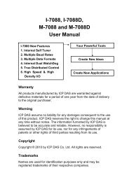
Main board picture:<br />
<strong>SBC6045</strong><br />
Timll Technic Inc<br />
<strong>User</strong> <strong>Manual</strong> Rev. 1.0 8 of 90
www.armkits.com<br />
<strong>SBC6045</strong> <strong>User</strong> <strong>Manual</strong><br />
POWER OUT<br />
LED&RUN<br />
Debug USB<br />
TWI SPI<br />
LVDS<br />
JTAG<br />
KEY<br />
Reset<br />
Mini-PCI Slot<br />
SDCARD<br />
ISO<br />
POWER<br />
AUDIO<br />
TOUCH<br />
SIM Card Slot<br />
CAN1<br />
Core board<br />
Connector<br />
CAN2<br />
DC 12V<br />
USB Host<br />
Ethernet 0<br />
Buzzer COM1 COM2 COM0 COM3<br />
Dimensions of PCB:185*125mm<br />
Connector pin definitions from board bottom to the core board, please refer to:3 Electrical<br />
Description<br />
<strong>SBC6045</strong><br />
Timll Technic Inc<br />
<strong>User</strong> <strong>Manual</strong> Rev. 1.0 9 of 90
www.armkits.com<br />
<strong>SBC6045</strong> <strong>User</strong> <strong>Manual</strong><br />
2.4 General system structure diagram<br />
<strong>SBC6045</strong><br />
Timll Technic Inc<br />
<strong>User</strong> <strong>Manual</strong> Rev. 1.0 10 of 90
www.armkits.com<br />
<strong>SBC6045</strong> <strong>User</strong> <strong>Manual</strong><br />
3 Description of interfaces<br />
3.1 LAYOUT<br />
SYSTEM LAYOUT DIAGRAM::<br />
Table 2-1 Interface Details<br />
3.2 POWER(J1)<br />
• Standard 3.81mm Wiring connector can be used to provide the po<strong>we</strong>r input +12 V<br />
• Input voltage range :12-36V<br />
• Isolated maximum po<strong>we</strong>r limit: 20W<br />
• The po<strong>we</strong>r can be protected by fuse, 1.5A limited<br />
• Interface pins are defined as follows: (FGND <strong>for</strong> the chassis ground)<br />
VCC 1<br />
GND 2<br />
<strong>SBC6045</strong><br />
Timll Technic Inc<br />
<strong>User</strong> <strong>Manual</strong> Rev. 1.0 11 of 90
www.armkits.com<br />
<strong>SBC6045</strong> <strong>User</strong> <strong>Manual</strong><br />
FGND 3<br />
Po<strong>we</strong>r input interface functional definition<br />
3.3 SDHC(SD/MMC)<br />
• High-speed SD card interface<br />
• Compatible SD / MMC interface card<br />
• 8-bit parallel bus data transfer mode<br />
• SD / MMC interface reference CPU res<strong>our</strong>ces as follows:<br />
PA22 MMC_CDA<br />
PA23 MMC_DA0<br />
PA24 MMC_DA1<br />
PA25 MMC_DA2<br />
PA26 MMC_DA3<br />
PA27 MMC_DA4<br />
SDHC PA28 MMC_DA5<br />
PA29 MMC_DA6<br />
PA30 MMC_DA7<br />
PA31 MMC_CK<br />
PB29 CD<br />
PB30 WP<br />
3.4 NET(J15)<br />
• the CPU built-in controller<br />
• Work speed: 100Mbps<br />
• Work mode: RMII<br />
• Output interface adopts RJ45 connectors<br />
• CPU res<strong>our</strong>ces as follows:<br />
NET<br />
PA10<br />
PA11<br />
PA12<br />
PA13<br />
PA14<br />
PA15<br />
EXT0<br />
EXT1<br />
ERX0<br />
ERX1<br />
ETXEN<br />
ERXDV<br />
<strong>SBC6045</strong><br />
Timll Technic Inc<br />
<strong>User</strong> <strong>Manual</strong> Rev. 1.0 12 of 90
www.armkits.com<br />
<strong>SBC6045</strong> <strong>User</strong> <strong>Manual</strong><br />
PA16<br />
PA17<br />
PA18<br />
PA19<br />
PD5<br />
ERXER<br />
E_TXCK<br />
EMDC<br />
EMDIO<br />
MDINT<br />
3.5 UART<br />
UART (DEBUG, COM0, COM1, COM2, COM3), all comes from the MCU res<strong>our</strong>ce controller<br />
3.5.1 DEBUG serial port (J23)<br />
• Serial DEBUG connector leads with 1132R<br />
• This interface uses 3-wire<br />
• Res<strong>our</strong>ces<br />
PC30 DRXD<br />
DEBUG PC31 DTXD<br />
DEBUG corresponds to DEBUG serial port from CPU (AT91SAM9G45) .<br />
J23 Pins definition :<br />
PIN<br />
Function<br />
1 DRRXD<br />
2 DRTXD<br />
3 GND<br />
4 NC<br />
• Signal input/output level: RS232<br />
• Data rate: 115.2kbps<br />
• Flow Control: None<br />
3.5.2 COM 0,2 (J25, J26)<br />
• COM 0,2 with DR9 male serial connector leads RS232 & RS485 level<br />
• COM 0,2 are 3-lines serial port<br />
• This feature provides directly from the CPU pins<br />
• Res<strong>our</strong>ces:<br />
PB19 TXD0<br />
PB18 RXD0<br />
UART0 PB17 RTS0<br />
PB6 TXD2<br />
PB7 RXD2<br />
UART2 PC9 RTS2<br />
<strong>SBC6045</strong><br />
Timll Technic Inc<br />
<strong>User</strong> <strong>Manual</strong> Rev. 1.0 13 of 90
www.armkits.com<br />
<strong>SBC6045</strong> <strong>User</strong> <strong>Manual</strong><br />
COM0、COM2 are a 5-wire universal serial port, it corresponds to USART0 and USART2 from<br />
CPU (AT91SAM9G45) .<br />
• Signal input/output level: RS232<br />
• Data rate: 115.2kbps<br />
• Flow Control: None<br />
• Connector: DR9 male<br />
At the same time the two ports also are used <strong>for</strong> RS485 functional interfaces, data from the<br />
CPU is sent out to two functional outputs simultaneously: meanwhile RS232 and RS485, the<br />
data from RS232 and RS485 interfaces can be sent back to the CPU.<br />
DR9 interface connector (J25,J26) Pin is defined as follow:<br />
COM0<br />
(J25)<br />
1 1<br />
2 RRXD0 2 RRXD2<br />
3 RTXD0 3 RTXD2<br />
4 4<br />
5 GND COM2 5 GND<br />
6 (J26) 6<br />
7 485A1 7 485A2<br />
8 485B1 8 485B2<br />
9 GND_ISO<br />
9 GND_ISO<br />
3.5.3 COM1(J20)<br />
• COM1 adopts DR9 with RS232 level<br />
• COM1 is 5- lines serial port<br />
• This function provides directly from the CPU pins<br />
• res<strong>our</strong>ces:<br />
PB4 TXD1<br />
PB5 RXD1<br />
PD16 RTS1<br />
COM1 PD17 CTS1<br />
COM1 is a 5-wire universal serial port, it corresponds to USART1 on MCU.<br />
• Signal input/output level: RS232<br />
• Data rate: 115.2kbps<br />
• Connector: DR9 Male<br />
• DR9 interface connector (J20) Pin is defined as follow:<br />
1<br />
2 RRXD1<br />
3 RTXD1<br />
4<br />
COM1 5 GND<br />
(J20) 6<br />
<strong>SBC6045</strong><br />
Timll Technic Inc<br />
<strong>User</strong> <strong>Manual</strong> Rev. 1.0 14 of 90
www.armkits.com<br />
<strong>SBC6045</strong> <strong>User</strong> <strong>Manual</strong><br />
7 RRTS1<br />
8 RCTS1<br />
9<br />
3.5.4 COM3(J27)<br />
• COM3 adopts wiring connector with RS232 level<br />
• COM3 is 3- lines serial port<br />
• The function operates with the J40 connector, if use the GPRS or CDMA modules, extending J27<br />
serial function and GPRS functions against J27 can not work at the same time.they just can work<br />
individually under the system.<br />
• This function provides directly from the CPU pins<br />
• res<strong>our</strong>ces:<br />
PB8 TXD3<br />
COM3 PB9 RXD3<br />
COM3 is a 3-wire universal serial port, it corresponds to USART3 on MCU.<br />
• Signal input/output level: RS232<br />
• Maximum data rate: 115.2kbps<br />
• Connector: Connector(J27/U40)<br />
Output interface (J27) pin is defined as follow:<br />
COM3 1 RRXD3<br />
2 RTXD3<br />
3 GND<br />
CAN2 4 GND_ISO<br />
5 CAN_L2<br />
6 CAN_H2<br />
CAN1 7 CAN_L1<br />
8 CAN_H1<br />
3.6 BUZZER(BUZZ)<br />
• res<strong>our</strong>ces:PB20<br />
• Low voltage effective(Active low)<br />
3.7 USB OTG(J11)<br />
• Mini USB connector<br />
• res<strong>our</strong>ces(HDMB,HDPB)<br />
• This interface connectors to the bottom board J11 and J19 connectors<br />
<strong>SBC6045</strong><br />
Timll Technic Inc<br />
<strong>User</strong> <strong>Manual</strong> Rev. 1.0 15 of 90
www.armkits.com<br />
<strong>SBC6045</strong> <strong>User</strong> <strong>Manual</strong><br />
• program can be written in or deleted from system via the miniUSB connector on core-board<br />
• This port with OTG function, can be used to connect the USB device on the MINIPCI backplane (such as<br />
3G module)<br />
3.8 USB HOST(CN1)<br />
• Standard Type A connector<br />
• res<strong>our</strong>ces(HDMA、HDPA)<br />
• Onboard Item NO:CN1<br />
• High-speed USB 2.0 communication interface<br />
3.9 TWI(J15)<br />
• System provide a TWI interface<br />
• Res<strong>our</strong>ces:PB10(TWD1),PB11(TWCK1)<br />
• Interfaces:J15<br />
• Pins definition:<br />
1 TWD<br />
TWI 2 TWCK<br />
3 GND<br />
4 WKUP<br />
3.10 AUDIO OUT(J9)<br />
• Standard 3.5mm audio in/out connector<br />
• 32 Ω Output Load (HP_OUT)<br />
• Res<strong>our</strong>ces:<br />
PD6 AC97RX<br />
PD7 AC97TK<br />
AC97 PD8 AC97FS<br />
(J9) PD9 AC97CK<br />
3.11 JTAG(J10)<br />
VDD33 1 2 VDD33<br />
NTRST 3 4 GND<br />
TDI 5 6 GND<br />
TMS 7 8 GND<br />
<strong>SBC6045</strong><br />
Timll Technic Inc<br />
<strong>User</strong> <strong>Manual</strong> Rev. 1.0 16 of 90
www.armkits.com<br />
<strong>SBC6045</strong> <strong>User</strong> <strong>Manual</strong><br />
TCK 9 10 GND<br />
RTCK 11 12 GND<br />
TDO 13 14 GND<br />
NRST 15 16 GND<br />
17 18 GND<br />
19 20 GND<br />
3.12 LCD(J20)<br />
• 40PIN FPC connects to connector interface<br />
• support interface mode 24/16bit mode (Default 16bit mode)<br />
• Supports maximum definition of 1280*860<br />
• This stand is located in the core board, Item NO:J5<br />
CPU signal res<strong>our</strong>ces Note:<br />
PE0 LCDPWR PE16 LCDD9<br />
PE1 LCDMOD PE17 LCDD10<br />
PE2 LCDCC PE18 LCDD11<br />
PE3 LCDVSYNC PE19 LCDD12<br />
PE4 LCDHSYNC PE20 LCDD13<br />
PE5 LCDDOTCK PE21 LCDD14<br />
PE6 LCDDEN PE22 LCDD15<br />
LCD PE7 LCDD0 PE23 LCDD16<br />
PE8 LCDD1 PE24 LCDD17<br />
PE9 LCDD2 PE25 LCDD18<br />
PE10 LCDD3 PE26 LCDD19<br />
PE11 LCDD4 PE27 LCDD20<br />
PE12 LCDD5 PE28 LCDD21<br />
PE13 LCDD6 PE29 LCDD22<br />
PE14 LCDD7 PE30 LCDD23<br />
PE15 LCDD8<br />
The connector of LCD interface located on the core-board, regarding to J5 on core-board,<br />
applies the upper connector, pin pitch of 0.5mm, and also integrates touch screen function. pin<br />
definition as below:<br />
VDD5V 1 2 VDD5V<br />
B0 3 4 B1<br />
B2 5 6 B3<br />
B4 7 8 B5<br />
B6 9 10 B7<br />
GND 11 12 G0<br />
G1 13 14 G2<br />
<strong>SBC6045</strong><br />
Timll Technic Inc<br />
<strong>User</strong> <strong>Manual</strong> Rev. 1.0 17 of 90
www.armkits.com<br />
<strong>SBC6045</strong> <strong>User</strong> <strong>Manual</strong><br />
G3 15 16 G4<br />
G5 17 18 G6<br />
G7 19 20 GND<br />
R0 21 22 R1<br />
R2 23 24 R3<br />
R4 25 26 R5<br />
R6 27 28 R7<br />
GND 29 30 PWREN<br />
LCDMOD 31 32 LCDCC<br />
LCDDEN 33 34 VSYNC<br />
HSYNC 35 36 DCLK<br />
X- 37 38 X+<br />
Y- 39 40 Y+<br />
LCD interface signal functional definition<br />
3.13 KEY(B1)<br />
• 2 keys:IO、TESET<br />
• Item NO:B1:PB31 ,B4:RESET<br />
3.14 TOUCH(J20)<br />
• Touch interface comes from 4pin FPC connector<br />
• Signal name:X+、X-、Y+、Y-<br />
• res<strong>our</strong>ce:It comes from CPU<br />
• functional res<strong>our</strong>ces:<br />
PD20 X+<br />
PD21 X-<br />
TOUCH PD22 Y+<br />
PD23 Y-<br />
The definition of interface J7 on Backplane pins are as below (the serial order of the two<br />
middle wire can be changed by wire jumper):<br />
Pin<br />
Function<br />
1 Y-<br />
2 X- (Y+)<br />
3 Y+ (X-)<br />
4 X+<br />
<strong>SBC6045</strong><br />
Timll Technic Inc<br />
<strong>User</strong> <strong>Manual</strong> Rev. 1.0 18 of 90
www.armkits.com<br />
<strong>SBC6045</strong> <strong>User</strong> <strong>Manual</strong><br />
3.15 LVDS(J3)<br />
• Connector:20PIN(10*2)pin headers,2.0mm<br />
• This interface via LCD interface TTL level transferred by the chip<br />
• Support 24-bit mode<br />
• This group of signals is converted into 24-bit LVDS interface signals by the chip of<br />
SN75LVDS83, which is located on the core board.the definition of J3 ports linked to back<br />
board by connector bet<strong>we</strong>en core board and the backplane as below:<br />
VDD33V 1 2 VDD33V<br />
GND 3 4 GND<br />
TA- 5 6 TA+<br />
GND 7 8 TB-<br />
TB+ 9 10 GND<br />
TC- 11 12 TC+<br />
GND 13 14 TCLK-<br />
TCLK+ 15 16 TD-<br />
TD+ 17 18<br />
19 20 VDD33V<br />
<strong>SBC6045</strong><br />
Timll Technic Inc<br />
<strong>User</strong> <strong>Manual</strong> Rev. 1.0 19 of 90
www.armkits.com<br />
<strong>SBC6045</strong> <strong>User</strong> <strong>Manual</strong><br />
3.16 LED(D20)<br />
• res<strong>our</strong>ces:PB21<br />
• Low voltage effective(Active low)<br />
• Wire connector J29 leads out the way IO , which is used as a system status indicator to use<br />
• J29 pin is defined as follow:<br />
LED<br />
1 VDD33V<br />
2 PB22(470R)<br />
3 VDD33V<br />
4 GND(470R)<br />
3.17 CAN(J26)<br />
• 2 CAN communication interface are extended through two groups of SPI controller<br />
• CAN2.0 communication interface<br />
• Res<strong>our</strong>ces :<br />
PB0 SPI0_MISO PB14 SPI1_MISO<br />
PB1 SPI0_MOSI PB15 SPI1_MOSI<br />
CAN1 PB2 SPI0_SPCK CAN2 PB16 SPI1_SPCK<br />
PD24 SPI0_NPCS1 PD18 SPI1_NPCS2<br />
PD25 INT<br />
PD26 INT<br />
CAN communication interface output to J27 Wiring connector is defined as follows:<br />
COM3 1 RRXD3<br />
2 RTXD3<br />
3 GND<br />
CAN2 4 GND_ISO<br />
5 CAN_L2<br />
6 CAN_H2<br />
CAN1 7 CAN_L1<br />
8 CAN_H1<br />
If the establishment of CAN networking needs terminal resistance ,it can be achieved by<br />
applying the jumper cap J13, J14 of matching resistor resistor.<br />
(Note: This terminal matching resistance can only be used at both ends of UTP, meanwhile mid<br />
device does not require)<br />
<strong>SBC6045</strong><br />
Timll Technic Inc<br />
<strong>User</strong> <strong>Manual</strong> Rev. 1.0 20 of 90
www.armkits.com<br />
<strong>SBC6045</strong> <strong>User</strong> <strong>Manual</strong><br />
3.18 SPI(J31)<br />
System provides a way SPI communication interface. Item NO:J31 pin are defined as follows::<br />
1 PB16<br />
2 PB14<br />
SPI 3 PB15<br />
4 PD19<br />
5 GND<br />
3.19 BUZZER(BUZZ)<br />
System hardware offers a buzzer, which can be a GPIO to control: PB20 (Active low):PB20<br />
(Active low)<br />
3.20 POWER OUT(J28)<br />
• system provides a po<strong>we</strong>r output interface ,which can be used to provide po<strong>we</strong>r <strong>for</strong> the external<br />
LCD<br />
• Specific output signal J28 following table:<br />
1 VDD12V<br />
2 GND<br />
J28 3 ON_OFF PB28<br />
4 DIMMING PD31<br />
5 VDD5V<br />
3.21 RTC<br />
The system extends a high-definition RTC through TWI interface, the battery on the backplane<br />
can be charged automatically .extended res<strong>our</strong>ce as below : PA20(SDA),PA21(SCL)<br />
4 System Electrical Description<br />
• Po<strong>we</strong>r input:range(12-36V)<br />
• Core board po<strong>we</strong>r supply:5V<br />
• Kinds of po<strong>we</strong>r:+1.2V,+1.8V,+3.3V,+5V,+12V,<br />
• Total po<strong>we</strong>r consumption:+12Vx0.25A (Without Screen)<br />
• Actual test po<strong>we</strong>r consumption:<br />
• Ambient temperature:-10-70℃<br />
<strong>SBC6045</strong><br />
Timll Technic Inc<br />
<strong>User</strong> <strong>Manual</strong> Rev. 1.0 21 of 90
www.armkits.com<br />
<strong>SBC6045</strong> <strong>User</strong> <strong>Manual</strong><br />
Core board connect to pin interface on bottom board is defined as follows:<br />
Pin(J8) Signal Pin(J8) Signal Pin(J6) Signal Pin(J6) Signal<br />
1 GND 41 GND 1 GND 41 SHDN<br />
2 TA- 42 TA+ 2 1V8 42 PC1<br />
3 TB- 43 TB+ 3 PC0 43 PC6<br />
4 TC- 44 TC+ 4 PC7 44 PC9<br />
5 TD- 45 TD+ 5 PC10 45 PC11<br />
6 TCLK- 46 TCLK+ 6 PC12 46 PC13<br />
7 GND 47 VDD33 7 PC15 47 PC16<br />
8 PD24 48 PD25 8 PC17 48 PC18<br />
9 PD26 49 PD27 9 PC19 49 PC20<br />
10 PA6 50 PE31 10 DRRXD 50 DRTXD<br />
11 PA8 51 PA7 11 PC21 51 PC22<br />
12 PA20 52 PA9 12 PC23 52 PC24<br />
13 PA22 53 PA21 13 PC25 53 PC26<br />
14 PA24 54 PA23 14 PC27 54 PC28<br />
15 PD20 55 PD22 15 PC29 55 PC30<br />
16 PD21 56 PD23 16 PC31 56 PD0<br />
17 PA28 57 PA27 17 PD6 57 PD7<br />
18 PA30 58 PA29 18 PD8 58 PD9<br />
19 PB0 59 PA31 19 GND 59 PD11<br />
20 PB2 60 PB1 20 GND 60 WKUP<br />
21 PB5 61 PB4 21 PD12 61 PD13<br />
22 PB7 62 PB6 22 PD14 62 PD15<br />
23 PB9 63 PB8 23 PD16 63 PD17<br />
24 PB11 64 PB10 24 PD18 64 PD19<br />
25 PA26 65 PA25 25 PD29 65 PD28<br />
26 66 GND 26 PD31 66 PD30<br />
27 PB15 67 PB14 27 PB20 67 PB21<br />
28 PB17 68 PB16 28 PB22 68 PB23<br />
29 PB19 69 PB18 29 PB24 69 PB25<br />
30 NRST 70 VDD5V 30 PB26 70 PB27<br />
31 PD10 71 VSBAT 31 PB28 71 PB29<br />
32 PA5 72 PA4 32 PB30 72 NTRST<br />
33 PA2 73 PA1 33 PB31 73 TDI<br />
34 PA3 74 PA0 34 RTCK 74 TDO<br />
35 GND 75 PB3 35 TCK 75 TMS<br />
36 LED4 76 LED5 36 USB_B_VB 76 USB_A_VB<br />
37 RX2- 77 RX2+ 37 HDPA 77 HDMA<br />
38 VDD33 78 AVDDT 38 VDD5V 78<br />
39 TX2- 79 TX2+ 39 HDPB 79 HDMB<br />
<strong>SBC6045</strong><br />
Timll Technic Inc<br />
<strong>User</strong> <strong>Manual</strong> Rev. 1.0 22 of 90
40 GND 80 VDD5V 40 GND 80 GND<br />
www.armkits.com<br />
<strong>SBC6045</strong> <strong>User</strong> <strong>Manual</strong><br />
Note:<br />
In addition the functions of on the core board,but also through 160PIN double straight leads out functions as<br />
follows:<br />
8-bit single channel LVDS interface (24-bit color)<br />
Network port differential line<br />
DEBUG serial port<br />
USART0-3<br />
USB OTG(HS)<br />
USB 2.0<br />
SPI*2<br />
TWI*2<br />
SDIO(HS)<br />
PWM<br />
ISI<br />
AC97<br />
TOUCH<br />
JTAG<br />
GPIOs<br />
<strong>SBC6045</strong><br />
Timll Technic Inc<br />
<strong>User</strong> <strong>Manual</strong> Rev. 1.0 23 of 90
www.armkits.com<br />
<strong>SBC6045</strong> <strong>User</strong> <strong>Manual</strong><br />
Chapter Three: Linux System<br />
5 Overview of Linux system<br />
<strong>SBC6045</strong> BSP mainly used <strong>for</strong> customization Linux <strong>for</strong> <strong>SBC6045</strong> hardware plat<strong>for</strong>m, <strong>you</strong> can do<br />
secondary development based on the development kit. The <strong>SBC6045</strong> CD provides the BSP packet<br />
that refers to table 1-1 content.<br />
Table 1-1 specification of <strong>SBC6045</strong> BSP<br />
Name<br />
Remark<br />
BIOS<br />
Kernel<br />
Device Driver<br />
Bootstrap<br />
u-boot<br />
Linux-2.6.x<br />
Serial<br />
RTC<br />
NET<br />
Flash<br />
LCD<br />
Touch Screen<br />
USB Host<br />
USB Device<br />
Watchdog<br />
SD Card<br />
NANDFLASH<br />
NAND<br />
NET and SAM-BA downloader image<br />
ROM/CRAM/EXT2/EXT3/FAT/NFS/<br />
JFFS2/YAFFS2..etc<br />
CPU DEBUG and f<strong>our</strong>-way Serial<br />
AT91SAM9G45 extended RTC driver<br />
10/100M Ethernet driver<br />
Nand Flash driver<br />
TFT LCD driver <strong>for</strong> 480x272 800x480 and 800x600<br />
Pixel LCD<br />
The CPU touch screen control<br />
USB Host driver<br />
USB Device driver<br />
Watchdog driver<br />
SD card driver<br />
EEPROM 2K bits EEPROM<br />
CAN Two-way extended CAN BUS driver<br />
RS-485 One-way extended RS-485<br />
LED LED driver<br />
BEEP Beep driver<br />
Root file system YAFFS2 RW file system<br />
Graphics QT Version number 4.4.2<br />
<strong>SBC6045</strong><br />
Timll Technic Inc<br />
<strong>User</strong> <strong>Manual</strong> Rev. 1.0 24 of 90
www.armkits.com<br />
<strong>SBC6045</strong> <strong>User</strong> <strong>Manual</strong><br />
6 Getting Start with <strong>SBC6045</strong><br />
Note:If <strong>you</strong> use the HyperTerminal on the PC when <strong>SBC6045</strong> is booting,<br />
please configure <strong>you</strong>r connection software like this:<br />
Baud rate:115200<br />
Data: 8bit;<br />
Parity:None<br />
Stop: 1bit<br />
Flow control: None<br />
6.1 Getting Start from Nandflash<br />
The development board support booting from nandflash.If <strong>you</strong> want to boot from the nandflash,<br />
<strong>you</strong> should close the J4 on the board. When out factory, <strong>we</strong> have downloader image to the nandflash.<br />
If <strong>you</strong> want to update the image, <strong>you</strong> can refer to the “Chapter 5 Update the System Image”.<br />
Note: The system image update can refer to【Chapter 5 Update the System Image】<br />
6.2 Setting the type of LCD Screen<br />
Now the development board driver support three types of LCD screen,there are 480x272,<br />
800x480, 800x600.<br />
Set the tft parameter <strong>for</strong> the LCD.and the kernel can loader driver <strong>for</strong> the LCD.The tft param is<br />
follow:<br />
LCD screen size LCD set parameter LCD pixel<br />
4.3 inch s 480x272<br />
7.0 inch m 800x480<br />
10.4 inch b 800x600<br />
Setting method is in the U-BOOT follow:<br />
U-Boot> set bootargs console=ttySAC0,115200 tft=s root=/dev/mtdblock6<br />
mtdparts=atmel_nand:128k(bootstrap)ro,256k(uboot)ro,128k(env1)ro,128k(env2)ro,1M(logo)ro<br />
,2M(linux),-(root) rw rootfstype=yaffs2<br />
7 Test Tutorials of the <strong>SBC6045</strong><br />
7.1 Touch Screen Test<br />
All about touch screen hardware connects can refer to “Hardware manual of <strong>SBC6045</strong> ”<br />
1. Enter the following command procedures <strong>for</strong> the implementation of touch screen calibration:<br />
[root@Mini6045:/]# ts_calibrate<br />
Follow the on-screen prompts, click the “+” icon five times to complete the calibration.<br />
2. Upon completion of calibration, enter the following commands <strong>for</strong> touch-screen test:<br />
<strong>SBC6045</strong><br />
Timll Technic Inc<br />
<strong>User</strong> <strong>Manual</strong> Rev. 1.0 25 of 90
www.armkits.com<br />
<strong>SBC6045</strong> <strong>User</strong> <strong>Manual</strong><br />
[root@Mini6045:/]# ts_test<br />
Follow the on-screen prompts, can choice of “draw point’ or “draw line” test.<br />
Note: pressing the Ctrl+C then exit the test program.<br />
7.2 Net Test<br />
There have a MACB 10/100M Ethernet on the development board, users can use it connect to<br />
network, and use following command to test:<br />
~ $ ifconfig eth0 192.192.192.200<br />
~ $ ping 192.192.192.105<br />
PING 192.192.192.105 (192.192.192.105): 56 data bytes<br />
64 bytes from 192.192.192.105: icmp_seq=0 ttl=64 time=0.5 ms<br />
64 bytes from 192.192.192.105: icmp_seq=1 ttl=64 time=0.3 ms<br />
64 bytes from 192.192.192.105: icmp_seq=2 ttl=64 time=0.3 ms<br />
64 bytes from 192.192.192.105: icmp_seq=3 ttl=64 time=0.3 ms<br />
64 bytes from 192.192.192.105: icmp_seq=4 ttl=64 time=0.3 ms<br />
64 bytes from 192.192.192.105: icmp_seq=5 ttl=64 time=0.3 ms<br />
64 bytes from 192.192.192.105: icmp_seq=6 ttl=64 time=0.3 ms<br />
--- 192.192.192.105 ping statistics ---<br />
7 packets transmitted, 7 packets received, 0% packet loss<br />
round-trip min/avg/max = 0.3/0.3/0.5 ms<br />
~ $<br />
Note: pressing the Ctrl+C then exit the test program.<br />
7.3 UART Test<br />
There are five serial ports on the development board,which CPU has 4,and each device namded <strong>for</strong> linux<br />
is “ttySAC0,ttySAC1,ttySAC2, ttySAC3 and ttySAC4” . “ttySAC0” is used <strong>for</strong> debug, “ttySAC1” and<br />
“ttySAC3” is used <strong>for</strong> RS-485(They also could be used <strong>for</strong> Serial). You can do test with the following<br />
commands. All about serial ports connect can refer to “Hardware manual of <strong>SBC6045</strong>”<br />
[root@Mini6045:/home/app]# ./com -d /dev/ttySAC1 -s 1234567890<br />
7.4 CAN Bus Test<br />
There are two extended CAN Bus device on the development board. All about the CAN Bus hardware connect<br />
can refer to “Hardware manual of <strong>SBC6045</strong>” .<br />
1. CAN receive test:<br />
[root@Mini6045:/]# cd /home/app/can/<br />
[root@Mini6045:/home/app/can]# ./receive can0<br />
This is received data.<br />
Received with ret=1: 1246986251.249889 id=1/0x00000001<br />
len=8 flags=0x00 : sD : msg= 00 11 22 33 44 55 66 77<br />
<strong>SBC6045</strong><br />
Timll Technic Inc<br />
<strong>User</strong> <strong>Manual</strong> Rev. 1.0 26 of 90
www.armkits.com<br />
<strong>SBC6045</strong> <strong>User</strong> <strong>Manual</strong><br />
Received with ret=1: 1246986252.701898 id=1/0x00000001<br />
len=8 flags=0x00 : sD : msg= 00 11 22 33 44 55 66 77<br />
Received with ret=1: 1246986254.069926 id=1/0x00000001<br />
len=8 flags=0x00 : sD : msg= 00 11 22 33 44 55 66 77<br />
2. CAN transmit test.<br />
[root@Mini6045:/home/app/can]# ./transmit can0<br />
Notes: Press CONTROL+C to terminate.<br />
7.5 RS-485 Test<br />
The RS-485 takes up serial device /dev/ttySAC1 and /dev/ttySAC3. Test methods, such as serial port can be<br />
tested solution, but only in hardware connect is different.<br />
7.6 USB Host Test<br />
There only one USB host device on the development board. Test the USB host will need a USB device<br />
(For example, a USB disk). When <strong>you</strong> plug in a USB device, system will print related in<strong>for</strong>mation on <strong>you</strong>r<br />
Hyper Terminal.<br />
usb 1-1: USB disconnect, address 2<br />
usb 1-1: new full speed USB device using at91_ohci and address 3<br />
usb 1-1: configuration #1 chosen from 1 choice<br />
scsi2 : SCSI emulation <strong>for</strong> USB Mass Storage devices<br />
scsi 2:0:0:0: Direct-Access Generic USB SD Reader 0.00 PQ: 0 ANSI: 2<br />
sd 2:0:0:0: [sda] 7744512 512-byte hardware sectors (3965 MB)<br />
sd 2:0:0:0: [sda] Write Protect is off<br />
sd 2:0:0:0: [sda] Assuming drive cache: write through<br />
sd 2:0:0:0: [sda] 7744512 512-byte hardware sectors (3965 MB)<br />
sd 2:0:0:0: [sda] Write Protect is off<br />
sd 2:0:0:0: [sda] Assuming drive cache: write through<br />
sda: sda1<br />
sd 2:0:0:0: [sdb] Attached SCSI removable disk<br />
sd 2:0:0:0: Attached scsi generic sg1 type 0<br />
Prompted by the above in<strong>for</strong>mation can be seen that usb disk device was identified as sda1. You<br />
can do test with the following command.<br />
1. <strong>User</strong>s can opera the usb disk after mount u-disk by following command, because Linux system<br />
is request must have a directory was used by usb disk.For example, <strong>you</strong> can mount it into /mnt<br />
directory and set vfat <strong>for</strong>mat.<br />
[root@Mini6045:/]# mount -t vfat /dev/sda1 /mnt/<br />
2. Enter into the directory and view files.<br />
[root@Mini6045:/]# cd /mnt/<br />
[root@Mini6045:/mnt]# ls<br />
3.Umount the usb disk<br />
<strong>SBC6045</strong><br />
Timll Technic Inc<br />
<strong>User</strong> <strong>Manual</strong> Rev. 1.0 27 of 90
www.armkits.com<br />
<strong>SBC6045</strong> <strong>User</strong> <strong>Manual</strong><br />
[root@Mini6045:/mnt]# cd /<br />
[root@Mini6045:/]# umount /mnt/<br />
Note: usb disk will identify as sda device by default, <strong>you</strong> can seen it from<br />
system prompt.<br />
7.7 RTC Test<br />
The development board has hardware clock chip used <strong>for</strong> store/restore system time. You can<br />
opera the RTC like this:<br />
1. View system clock in<strong>for</strong>mation<br />
[root@Mini6045:/]# date<br />
Thu May 27 11:48:02 UTC 2010<br />
2. Change the date, like July 10 09:01 2009.<br />
[root@Mini6045:/]# date 201005271149<br />
Thu May 27 11:49:00 UTC 2010<br />
3.Save the system clock to RTC<br />
[root@Mini6045:/]# hwclock -w<br />
4. View RTC clock in<strong>for</strong>mation<br />
[root@Mini6045:/]# hwclock -r<br />
Thu May 27 11:49:07 2010 0.000000 seconds<br />
5. Restore the RTC backup to system.<br />
[root@Mini6045:/]# hwclock -s<br />
[root@Mini6045:/]# date<br />
Thu May 27 11:49:45 UTC 2010<br />
7.8 EEPROM Test<br />
In Linux system, the EEPROM device was regarded as a virtual file, <strong>you</strong> can use the following command<br />
to operate the EEPROM.<br />
1. Write data to EEPROM<br />
[root@Mini6045:/]# echo "aaa" >/sys/bus/i2c/devices/0-0050/eeprom<br />
2. Read data from EEPROM<br />
[root@Mini6045:/]# cat /sys/bus/i2c/devices/0-0050/eeprom<br />
7.9 SD Card Test<br />
Insert in SD card, the system will print the following in<strong>for</strong>mation. <strong>User</strong> can execute the following<br />
mount command to mount SD card and access SD card.<br />
<strong>SBC6045</strong><br />
Timll Technic Inc<br />
<strong>User</strong> <strong>Manual</strong> Rev. 1.0 28 of 90
[root@Mini6045:/]# mmc1: new SD card at address 0002<br />
mmcblk0: mmc1:0002 N/A 489 MiB<br />
mmcblk0: p1<br />
www.armkits.com<br />
<strong>SBC6045</strong> <strong>User</strong> <strong>Manual</strong><br />
Prompted by the above in<strong>for</strong>mation can be seen that SD card was identified as mmcblk0p1. You<br />
can do test with the following command.<br />
1. <strong>User</strong>s can opera the SD card after mount SD card by following command, because Linux<br />
system is request must have a directory was used by SD card . For example, <strong>you</strong> can mount it into<br />
/mnt directory and set vfat <strong>for</strong>mat.<br />
[root@Mini6045:/]# mount -t vfat /dev/mmcblk0p1 /mnt/<br />
2. Enter into the directory and view files.<br />
[root@Mini6045:/]# cd /mnt/<br />
[root@Mini6045:/mnt]# ls<br />
3. Umount theSD card<br />
[root@Mini6045:/mnt]# cd /<br />
[root@Mini6045:/]# umount /mnt/<br />
Note: SD card will identify as mmcblk0p1 device by default, <strong>you</strong> can seen it<br />
from system prompt.<br />
7.10 LED Test<br />
There are some leds on the development board, they are used as indication. You can do test with following<br />
command.<br />
1. Turn on led (D20)<br />
[root@Mini6045:/]# echo '0' >/sys/class/leds/d7/brightness<br />
2. Turn off led (D20)<br />
[root@Mini6045:/]# echo '1' >/sys/class/leds/d7/brightness<br />
7.11 Beep Test<br />
There have a Beep driving circuit on the development board. You can operate the Beep like this:<br />
1. Beep ring<br />
[root@Mini6045:/]# echo '1' >/sys/class/leds/beep/brightness<br />
2. Beep stop<br />
[root@Mini6045:/]# echo '0' >/sys/class/leds/beep/brightness<br />
8 Setting the Development Environment<br />
Be<strong>for</strong>e development the <strong>SBC6045</strong>, users must setup arm-linux cross development environment.<br />
Following the example of Ubuntu operating system(Linux).<br />
<strong>SBC6045</strong><br />
Timll Technic Inc<br />
<strong>User</strong> <strong>Manual</strong> Rev. 1.0 29 of 90
www.armkits.com<br />
<strong>SBC6045</strong> <strong>User</strong> <strong>Manual</strong><br />
8.1 Install the Cross Compiler<br />
If <strong>you</strong> have not installed arm-none-linux-gnueabi-gcc, copy<br />
“/media/cdrom/linux/tools/arm-2007q1-10-arm-none-linux-gnueabi-i686-pc-linux-gnu.tar.bz2” (from<br />
CD) to the folder of Linux system.<br />
The installation command is:<br />
mkdir /usr/local/arm<br />
tar –jxvf arm-2007q1-10-arm-none-linux-gnueabi-i686-pc-linux-gnu.tar.bz2 –C /usr/local/arm<br />
8.2 Setting the Cross-compiler Environment<br />
Define the path of compiler after installation is completed.<br />
export PATH=/usr/local/arm/arm-2007q1/bin/:$PATH<br />
Note:You can copy it to “.bashrc” file, that it’ll add the PATH automatically when OS is booting.<br />
8.3 Compiler the System of the <strong>SBC6045</strong><br />
8.3.1 Ready to Compiler Files<br />
All components of the system’s s<strong>our</strong>ce is located in “linux/s<strong>our</strong>ce” directory, <strong>you</strong> must<br />
decompression the files be<strong>for</strong>e development.<br />
For example:<br />
root@LINUXSERVER:~# mkdir embest<br />
root@LINUXSERVER:~# cd embest/<br />
root@LINUXSERVER:~/embest# cp /media/cdrom/02\ Linux\ 2.6\ Kit/01\<br />
S<strong>our</strong>ceCode/bootloader/Bootstrap-v1.14.tar.bz2 ./<br />
root@LINUXSERVER:~/embest# cp /media/cdrom/02\ Linux\ 2.6\ Kit/01\<br />
S<strong>our</strong>ceCode/bootloader/u-boot-1.3.4.tar.bz2 ./<br />
root@LINUXSERVER:~/embest# cp /media/02\ Linux\ 2.6\ Kit/01\ S<strong>our</strong>ceCode/kernel<br />
/linux-2.6.30.tar.bz2 ./<br />
root@LINUXSERVER:~/embest#<br />
cp /media/cdrom/02\ Linux\ 2.6\ Kit/01\ S<strong>our</strong>ceCode/rfs/rfs-qtopia.tar.bz2 ./<br />
root@LINUXSERVER:~/embest# mkdir tools<br />
root@LINUXSERVER:~/embest# cd tools/<br />
root@LINUXSERVER:~/embest/tools#<br />
cp /media/cdrom/02\ Linux\ 2.6\ Kit/02\ Tools/mkyaffs2image ./<br />
root@LINUXSERVER:~/embest/tools#<br />
cp /media/cdrom/02\ Linux\ 2.6\ Kit/02\ Tools/mkimage ./<br />
root@LINUXSERVER:~/embest/tools# export PATH=/root/embest/tools:$PATH<br />
root@LINUXSERVER:~/embest/tools# cd ../<br />
root@LINUXSERVER:~/embest# tar jxvf Bootstrap-v1.14.tar.bz2<br />
<strong>SBC6045</strong><br />
Timll Technic Inc<br />
<strong>User</strong> <strong>Manual</strong> Rev. 1.0 30 of 90
www.armkits.com<br />
<strong>SBC6045</strong> <strong>User</strong> <strong>Manual</strong><br />
root@LINUXSERVER:~/embest# tar jxvf u-boot-1.3.4.tar.bz2<br />
root@LINUXSERVER:~/embest# tar jxvf linux-2.6.30.tar.bz2<br />
root@LINUXSERVER:~/embest# tar jxvf rfs-qtopia.tar.bz2<br />
When operation <strong>for</strong> complete, that <strong>you</strong> can see linux-2.6.30、u-boot-1.3.4、Bootstrap-v1.14、<br />
rfs-qtopia f<strong>our</strong> directory will be generated under the current folder.<br />
8.3.2 The First Booting Stage -AT91Bootstarp<br />
<strong>SBC6045</strong> development board is support <strong>for</strong> boot from nandflash, following commands will be<br />
generated nandflash_at91sam9g45ekes.bin binary file.<br />
root@LINUXSERVER:~/embest# cd Bootstrap-v1.14<br />
root@LINUXSERVER:~/embest/Bootstrap-v1.14# cd board/at91sam9g45ekes/nandflash<br />
root@LINUXSERVER:~/embest/Bootstrap-v1.14/board/at91sam9g45ekes/nandflash# make<br />
When operation <strong>for</strong> complete,<strong>we</strong> need nandflash_at91sam9g45ekes.bin binary file in the current<br />
directory.<br />
8.3.3 The Second Booting Stage-U-boot<br />
U-boot is used in the second booting stage of <strong>SBC6045</strong>, enter the following commands in the<br />
terminal, u-boot.bin will be generated under current folder.<br />
root@LINUXSERVER:~/embest/u-boot-1.3.4# make at91sam9g45ekes_nandflash_config<br />
root@LINUXSERVER:~/embest/u-boot-1.3.4# make<br />
When operation <strong>for</strong> complete, <strong>we</strong> need u-boot.bin binary file in the current directory.<br />
8.3.4 The Third Booting Stage-Kernel<br />
You can use the follow commands to complier kernel:<br />
root@LINUXSERVER:~/embest/linux-2.6.30#<br />
cp arch/arm/configs/<strong>SBC6045</strong> _defconfig .config<br />
root@LINUXSERVER:~/embest/linux-2.6.30# make menuconfig<br />
root@LINUXSERVER:~/embest/linux-2.6.30# make uImage<br />
Wait the compilation of uImage to be finished, and found it under /arch/arm/boot/ folder.<br />
8.3.5 Make Root File System Image<br />
Use the follow commands to generated rfs.yaffs2 file as <strong>we</strong> need with tool program “02 Linux 2.6<br />
Kit\02 Tools\mkyaffs2image” in CD.<br />
root@LINUXSERVER:~/embest# mkyaffs2image rfs/ rfs.yaffs2<br />
8.4 System Customization<br />
In fact, there are many kernel configuration options at Linux kernel, users can Increase or<br />
reduction of kernel features, make better suited to the needs of users. The next chapter is an example<br />
<strong>for</strong> kernel configuration process.<br />
Kernel s<strong>our</strong>ce code in the factory provided the default configuration file:<br />
arch/arm/configs/<strong>SBC6045</strong>_defconfig<br />
<strong>User</strong>s can custom system base on the default configuration file.<br />
root@LINUXSERVER:~/embest/linux-2.6.30#<br />
<strong>SBC6045</strong><br />
Timll Technic Inc<br />
<strong>User</strong> <strong>Manual</strong> Rev. 1.0 31 of 90
www.armkits.com<br />
<strong>SBC6045</strong> <strong>User</strong> <strong>Manual</strong><br />
cp arch/arm/configs/<strong>SBC6045</strong>_defconfig .config<br />
root@LINUXSERVER:~/embest/linux-2.6.30# make menuconfig<br />
The following configure <strong>for</strong> each driver Help:<br />
RTC Driver:<br />
1.Select Device drivers<br />
2.Select Real Time Clock<br />
3.Select Maxim/Dallas DS3231<br />
Watchdog Driver<br />
1.Select Device drivers<br />
2.Select Watchdog Timer Support<br />
3.Select AT91SAM9 watchdog<br />
MACB Driver<br />
1.Select Device Drivers<br />
2.Select Network device support<br />
3.Select Ethernet(10 or 100Mbit)<br />
3.Select Atmel MACB support<br />
Graphics support<br />
1.Select Device Drivers<br />
2.Select Graphics support<br />
3.Select Support <strong>for</strong> frame buffer devices<br />
4.Select AT91/AT32 LCD Controller support<br />
Touch Screen Driver<br />
1.Select Device Drivers<br />
2.Select Input device support<br />
3.Select Touchscreens<br />
4.Select Atmel Touchscreen Interface<br />
Save the config,compile the kernel by follow command:<br />
root@LINUXSERVER:~/embest/linux-2.6.24# make uImage<br />
<strong>SBC6045</strong><br />
Timll Technic Inc<br />
<strong>User</strong> <strong>Manual</strong> Rev. 1.0 32 of 90
www.armkits.com<br />
<strong>SBC6045</strong> <strong>User</strong> <strong>Manual</strong><br />
9 Update the System Image<br />
The development board with Nandflash, currently supports nandflash from startup.<br />
9.1 System Image Map<br />
The Map of Nandflash Startup<br />
0x003A0000<br />
0x001A0000<br />
0x000A0000<br />
0x00080000<br />
0x00060000<br />
0x00020000<br />
0x00000000<br />
Rootfs(YAFFS2)<br />
Kernel<br />
Logo<br />
U-boot ENV2<br />
U-boot ENV1<br />
U-boot<br />
AT91BootStrap<br />
NANDFLASH<br />
Figure 5.1<br />
Nandflash image map<br />
9.2 Setting the Environment of Burning Image<br />
Install the application 02 Linux2.6 Kit\02 Tools\Install AT91-ISP v1.13.exe (or higher) in <strong>you</strong>r PC.<br />
You will see the icon SAM-BA v2.9 appearing on the desktop of PC.<br />
9.3 Burning System Image<br />
9.3.1 Burn the Image of the first stage –AT91BootStarp<br />
‣ Connect debug serial port. About hardware connects can refer to “Hardware manual of <strong>SBC6045</strong> ”.<br />
‣ Connect USB to <strong>you</strong>r PC using USB cable.<br />
‣ Make sure no SD card in the development board.<br />
<strong>SBC6045</strong><br />
Timll Technic Inc<br />
<strong>User</strong> <strong>Manual</strong> Rev. 1.0 33 of 90
www.armkits.com<br />
<strong>SBC6045</strong> <strong>User</strong> <strong>Manual</strong><br />
‣ Open the HyperTerminalon the PC, config the baud 115200, 8 bit data, 1 bit stop, none parity,<br />
none Flow control.<br />
‣ Be<strong>for</strong>e po<strong>we</strong>r on, open the J1, J4 and J10. Then po<strong>we</strong>r on.<br />
‣ Double click the SAMBA v2.9 cursor on the desktop of the PC.<br />
Figure 5.3.1 SAM-BA v2.9 software icons<br />
‣ Shown in the figure below, select “at91sam9g45-ek” and “\usb\ARM0”, and click “Connect”.<br />
Figure 5.3.2 SAM-BA startup interface<br />
‣ After click “Connect”, then entering SAM-BA software.<br />
Figure 5.3.3 SAM-BA burn interface<br />
‣ Close the J4, select “nandflash” tab. Then select the options “Enable NandFlash)” at “Scripts”<br />
Pull-down menus, then click “Execute”. Shown in the figure below:<br />
<strong>SBC6045</strong><br />
Timll Technic Inc<br />
<strong>User</strong> <strong>Manual</strong> Rev. 1.0 34 of 90
www.armkits.com<br />
<strong>SBC6045</strong> <strong>User</strong> <strong>Manual</strong><br />
Figure 5.3.4 SAM-BA enable the nandflash<br />
‣ At “Scripts” Pull-down menus, select “Erase All”, and click “Execute”, wait <strong>for</strong> a moment, <strong>you</strong><br />
can see nandflash will be erased.<br />
<strong>SBC6045</strong><br />
Timll Technic Inc<br />
<strong>User</strong> <strong>Manual</strong> Rev. 1.0 35 of 90
www.armkits.com<br />
<strong>SBC6045</strong> <strong>User</strong> <strong>Manual</strong><br />
Figure 5.3.5 SAM-BA erase nandflash interface<br />
‣ At “Scripts” Pull-down menus, select “Scrub NandFlash”, and click “Execute”, wait <strong>for</strong> a<br />
moment, <strong>you</strong> can see nandflash will be Erased.<br />
<strong>SBC6045</strong><br />
Timll Technic Inc<br />
<strong>User</strong> <strong>Manual</strong> Rev. 1.0 36 of 90
www.armkits.com<br />
<strong>SBC6045</strong> <strong>User</strong> <strong>Manual</strong><br />
Figure 5.3.6 SAM-BA erase nandflash interface<br />
‣ At “Scripts” Pull-down menus, select “Send Boot File”, and click “Execute”.<br />
Figure 5.3.7 SAM-BA burn nandlash_at91sam9g45ekes.bin<br />
<strong>SBC6045</strong><br />
Timll Technic Inc<br />
<strong>User</strong> <strong>Manual</strong> Rev. 1.0 37 of 90
www.armkits.com<br />
<strong>SBC6045</strong> <strong>User</strong> <strong>Manual</strong><br />
‣ When <strong>you</strong> click "Execute", <strong>you</strong> will open a dialog box, select<br />
“nandflash_at91sam9g45ekes.bin” and click open. Then <strong>you</strong> can download this file to target<br />
board.<br />
Figure 5.3.8 SAM-BA burn nand_at91sam9g45ekes.bin<br />
9.3.2 Burn the Image of second booting stage u-boot.<br />
Burn the u-boot.bin file to nandflash through SAM-BA.<br />
‣ Enter the downloader address of U-boot in the “address” field: “0x20000”<br />
<strong>SBC6045</strong><br />
Timll Technic Inc<br />
<strong>User</strong> <strong>Manual</strong> Rev. 1.0 38 of 90
www.armkits.com<br />
<strong>SBC6045</strong> <strong>User</strong> <strong>Manual</strong><br />
Figure 5.3.9 SAM-BA burn u-boot.bin<br />
‣ Open the “Send File Name” browse window, click “open folder” button.<br />
<strong>SBC6045</strong><br />
Timll Technic Inc<br />
<strong>User</strong> <strong>Manual</strong> Rev. 1.0 39 of 90
www.armkits.com<br />
<strong>SBC6045</strong> <strong>User</strong> <strong>Manual</strong><br />
Figure 5.3.10 SAM-BA burn u-boot.bin<br />
‣ You will open a dialog box, select “u-boot.bin” and click open<br />
Figure 5.3.11 SAM-BA burn u-boot.bin<br />
‣ Then download “u-boot.bin” to target board dataflash, click “Send File” button to burn<br />
“u-boot.bin” file to nandflash.<br />
9.3.3 Burn the Logo Image –Logo<br />
Burn “logo.bin” file to nandflash through SAM-BA.<br />
‣ Enter the downloader address of uImage in the “address” field:”0xA0000”.<br />
<strong>SBC6045</strong><br />
Timll Technic Inc<br />
<strong>User</strong> <strong>Manual</strong> Rev. 1.0 40 of 90
www.armkits.com<br />
<strong>SBC6045</strong> <strong>User</strong> <strong>Manual</strong><br />
Figure 5.3.12 SAM-BA burn logo.bin to nandflash<br />
‣ Open the “Send File Name” browse window, click “open folder” button.<br />
Figure 5.3.13 SAM-BA burn logo.bin to nandflash<br />
<strong>SBC6045</strong><br />
Timll Technic Inc<br />
<strong>User</strong> <strong>Manual</strong> Rev. 1.0 41 of 90
www.armkits.com<br />
<strong>SBC6045</strong> <strong>User</strong> <strong>Manual</strong><br />
‣ Open the “Send File Name” browse window, select “logo.bin”,as shown in the figure below.<br />
‣ Click “Send File” button to burn “logo.bin” to nandflash.<br />
9.3.4 Burn the Image of the third booting –kenel<br />
Burn “uImage” file to nandflash through SAM-BA.<br />
‣ Enter the downloader address of uImage in the “address” field:”0x1A0000”.<br />
Figure 5.3.14 SAM-BA burn uImage to nandflash<br />
‣ Open the “Send File Name” browse window, click “open folder” button.<br />
<strong>SBC6045</strong><br />
Timll Technic Inc<br />
<strong>User</strong> <strong>Manual</strong> Rev. 1.0 42 of 90
www.armkits.com<br />
<strong>SBC6045</strong> <strong>User</strong> <strong>Manual</strong><br />
Figure 5.3.15 SAM-BA burn uImage binary file<br />
‣ Open the “Send File Name” browse window, then <strong>you</strong> should select “All Files (*.*)” in the “files<br />
of type”, select “uImage”,as shown in the figure below.<br />
Figure 5.3.1.16<br />
SAM-BA burn uImage to nandflash<br />
<strong>SBC6045</strong><br />
Timll Technic Inc<br />
<strong>User</strong> <strong>Manual</strong> Rev. 1.0 43 of 90
www.armkits.com<br />
<strong>SBC6045</strong> <strong>User</strong> <strong>Manual</strong><br />
‣ Click “Send File” button to burn “uImage” to nandflash.<br />
9.3.4 Burn the Image of the f<strong>our</strong>th booting stage –file system<br />
‣ Make target board connect to network.<br />
‣ Set tftpd server and download folder. Copy tftpd.exe in the CD’s 02 Linux2.6 Kit/02 Tools folder to<br />
<strong>you</strong>r PC.<br />
Figure 5.3.17 Tftpd.exe software icon<br />
‣ Double click “tftpd.exe “, the following picture will appear on the screen.<br />
Figure 5.3.18 Tftpd.exe open interface<br />
‣ Click “Tftpd “, and click the option “Configure “ in its pulldown menu.<br />
Figure 5.3.19 Tftpd.exe config interface<br />
‣ Press the button Browse, the following picture will appear on the screen, select “image record”,<br />
and click “OK “ button.<br />
<strong>SBC6045</strong><br />
Timll Technic Inc<br />
<strong>User</strong> <strong>Manual</strong> Rev. 1.0 44 of 90
www.armkits.com<br />
<strong>SBC6045</strong> <strong>User</strong> <strong>Manual</strong><br />
Figure 5.3.20 Tftpd.exe config interface<br />
‣ Click “Tftpd “, and click the option “Start “ in its pull-down menu.<br />
‣ The TFTP Server set OK.<br />
Figure 5.3.21 startup tftpd server<br />
Figure 5.3.22 Tftpd server running<br />
‣ Turn on the target board po<strong>we</strong>r, when the U-Boot enter the countdown, press the space key of<br />
the keyboard. Then U-Boot enter download image mode.<br />
<strong>SBC6045</strong><br />
Timll Technic Inc<br />
<strong>User</strong> <strong>Manual</strong> Rev. 1.0 45 of 90
www.armkits.com<br />
<strong>SBC6045</strong> <strong>User</strong> <strong>Manual</strong><br />
Figure 5.3.23 U-boot startup interface<br />
‣ Set the target board IP and server IP, gateway IP in the U-boot<br />
U-Boot> setenv serverip 192.192.192.71<br />
U-Boot> setenv ipaddr 192.192.192.200<br />
U-Boot> setenv ethaddr 00:11:22:33:44:55<br />
U-Boot> saveenv<br />
‣ Erase the nandflash space from 0x3a0000<br />
U-Boot> nand erase 0x3a0000<br />
U-Boot> nand scrub 0x3a0000<br />
‣ Use the nand write.yaffs command to download the uImage the nandflash.<br />
U-Boot> tftp 0x20000000 rfs-qtopia.yaffs2<br />
‣ Copy the rootfs to nandflash .<br />
U-Boot> nand write.yaffs 0x20000000 0x3a0000 $(filesize)<br />
‣ The file system has been burned to the nandflash. You can reset the po<strong>we</strong>r.<br />
10 QT Demo<br />
You can enter the following command to start Qtopia application process.<br />
1. Enter the following command procedures <strong>for</strong> the implementation of touch screen calibration:<br />
[root@Mini6045:/]# ts_calibrate<br />
Follow the on-screen prompts, click the “+” icon five times to complete the calibration.<br />
<strong>SBC6045</strong><br />
Timll Technic Inc<br />
<strong>User</strong> <strong>Manual</strong> Rev. 1.0 46 of 90
2. <strong>you</strong> can start the Qtopia application process with the following command.<br />
[root@Mini6045:/]# qpe<br />
Then the following pictures will be shown.<br />
www.armkits.com<br />
<strong>SBC6045</strong> <strong>User</strong> <strong>Manual</strong><br />
<strong>SBC6045</strong><br />
Timll Technic Inc<br />
<strong>User</strong> <strong>Manual</strong> Rev. 1.0 47 of 90
www.armkits.com<br />
<strong>SBC6045</strong> <strong>User</strong> <strong>Manual</strong><br />
Chapter F<strong>our</strong>: Introduction of Wince6.0 System<br />
11.1 Image files related to <strong>SBC6045</strong> WinCE 6.0 system<br />
If WinCE system is customized using <strong>SBC6045</strong> WinCE 6.0 BSP that <strong>we</strong> provide and the<br />
compilation is successfully finished, the system will generate 6 image files, i.e.: FIRSTBOOT.nb0,<br />
EBOOT.nb0, NK.nb0, FIRSTBOOT.bin, EBOOT.bin, NK.bin, of which 4 files are usually used in<br />
burning processes, i.e.: FIRSTBOOT.nb0, EBOOT.nb0, NK.nb0, NK.bin. The files generated in .nb0<br />
<strong>for</strong>mat will finally be burnt to Dataflash or NAND flash, and they can directly run in SDRAM; while the<br />
files in .bin <strong>for</strong>mat must first be converted into .nb0 files by EBOOT running on <strong>SBC6045</strong> main board<br />
nb0, then they are burnt to Dataflash or NAND flash.<br />
11.2 Principle of <strong>SBC6045</strong> WinCE 6.0<br />
At prsent <strong>SBC6045</strong> WinCE 6.0 BSP Support NAND flash boot 。booting flow chart as follow:<br />
Figure11.2.1<br />
The ROOMBOOT Code fixed inside the CPU will automatically running after po<strong>we</strong>r on,The<br />
ROMBOOT will check if there is a valid BOOTLOADER in nandflash.If yes the ROMBOOT programer<br />
will copy the BOOTLODER to the SRAM inside of the CPU and execute it .otherwise it will ignore the<br />
nand flash and jump to the Serial port download and excute program .<br />
11.3 Principles on the booting of <strong>SBC6045</strong> WinCE 6.0 system<br />
After po<strong>we</strong>r on the system is fixed inside CPU of AT91SAM9G45, ROMBOOT will automatically<br />
copy FIRSTBOOT image, the first-level user booting code from NANDflash 0x00000000 address to<br />
SRAM inside of AT91SAM9G45 and execute it. FIRSTBOOT’s role is to initialize SDRAM memory,<br />
NANDflash in AT91SAM9G45, and copy EBOOT, the second-level user booting code from<br />
NANDflash 0x00020000 address of SBC6300X main board to SDRAM of AT91SAM9G45 main board<br />
and execute it; FIRSTBOOT also copy Logo from NANDflash 0x00080000 address to SDRAM. In<br />
default state, EBOOT will automatically copy WinCE system image NK from NAND flash 0x00200000<br />
<strong>SBC6045</strong><br />
Timll Technic Inc<br />
<strong>User</strong> <strong>Manual</strong> Rev. 1.0 48 of 90
www.armkits.com<br />
<strong>SBC6045</strong> <strong>User</strong> <strong>Manual</strong><br />
address to SDRAM, and hand over system control to operating system. In addition, EBOOT<br />
undertakes the management operations of underlying hardware and settings of the data shared with<br />
operating system.booting flow chart as figure 11.3.2.<br />
figure 11.3.2<br />
NANDFLASH memory mapping as follow:<br />
<strong>SBC6045</strong><br />
Timll Technic Inc<br />
<strong>User</strong> <strong>Manual</strong> Rev. 1.0 49 of 90
www.armkits.com<br />
<strong>SBC6045</strong> <strong>User</strong> <strong>Manual</strong><br />
Figure 11.3.3<br />
12 Charpter 12 Burning of WinCE system<br />
12.1 Introduction of buring Image of <strong>SBC6045</strong> WinCE 6.0<br />
Now <strong>our</strong> <strong>SBC6045</strong> WinCE 6.0 BSP supports two burning modes, first, burn FIRSTBOOT,<br />
EBOOT and WinCE system image NK using the SAM-BA software that ATMEL provides; second,<br />
connect VS2005 WinCE 6.0 development environment installed on client development workstation or<br />
other TFTP servers (e.g.: CEDownload.exe) to <strong>SBC6045</strong> main board, burn WinCE system image files<br />
NK via net cable using the EBOOT on <strong>SBC6045</strong> (the EBOOT that <strong>SBC6045</strong> WinCE 6.0 BSP of<br />
current version generates doesn’t support <strong>for</strong> the burning of user booting codes FIRSTBOOT and<br />
EBOOT, it can only burn WinCE system image file NK.bin) .<br />
Important: if <strong>you</strong> use EBOOT, the user booting code on <strong>SBC6045</strong> main board to WinCE system<br />
image file NK, the actual process will be, EBOOT, the user booting code on <strong>SBC6045</strong> main board will<br />
first download WinCE system image file NK.bin that VS2005 WinCE 6.0 generates from TFTP server<br />
running on development workstation to SDRAM on<strong>SBC6045</strong> main board via net cable, then the file<br />
will be converted into NK.nb0 be<strong>for</strong>e being burnt to NAND flash. The TFTP server mentioned here<br />
can be the server provided in VS2005 WinCE 6.0 development environment or other TFTP servers.<br />
Please note that the port parameter of the TFTP server that <strong>you</strong> use is 980 instead of 69, the standard<br />
TFTP port. The software CEDownload.exe, which <strong>we</strong> will describe in Section 3.4 below is a TFTP<br />
server software, which has changed the default TFTP port from 69 into 980.<br />
<strong>SBC6045</strong><br />
Timll Technic Inc<br />
<strong>User</strong> <strong>Manual</strong> Rev. 1.0 50 of 90
www.armkits.com<br />
<strong>SBC6045</strong> <strong>User</strong> <strong>Manual</strong><br />
12.2 Burn <strong>SBC6045</strong> WinCE 6.0 image through SAM-BA<br />
12.2.1Install SAM-BA software<br />
Install the application \02 Linux 2.6 Kit\02 Tools \Install AT91-ISP v1.13.exe in <strong>SBC6045</strong> CD on<br />
<strong>you</strong>r development workstation as the default path and configurations of AT91-ISP v1.13.exe<br />
program. After the installation is finished, <strong>you</strong> will see the icon of SAM-BA v2.9 (see Figure 12.2.1)<br />
appearing on the desktop :<br />
Figure 12.2.1<br />
‣ Connect the Debug serial COM port.<br />
‣ Connect USB device port to USB Host of the development workstation using the USB cable..<br />
‣ Open the hyper terminal on the PC and setting as :115200 8n1 no CRC and no flow control.<br />
‣ Remove the jumper cap of J4、J10 and J1 be<strong>for</strong>e po<strong>we</strong>r on .<br />
‣ Double click the icon of the application SAM-BA v2.9on desktop.<br />
Figure 12.2.1 SAM-BA v2.9<br />
As shown in Figure 12.2.1 to run SAM-BA 2.9 program,and select“Select the<br />
connection”and“\usb\ARM0”from the pulldown menu as shown in Figure 12.2.2.<br />
Figure 12.2.2 SAM-BA<br />
Click “Connect” button as shown in Figure 12.2.2,enter the interface as show in Figure 12.2.3<br />
below.<br />
<strong>SBC6045</strong><br />
Timll Technic Inc<br />
<strong>User</strong> <strong>Manual</strong> Rev. 1.0 51 of 90
www.armkits.com<br />
<strong>SBC6045</strong> <strong>User</strong> <strong>Manual</strong><br />
Figure 12.2.3<br />
1. Connect the jump J4 .As show in Figure 12.2.4 in the Scripts pulldown menu of SAM-BA v2.9,<br />
select Enable NandFlash, and click Execute button in the column Scripts to enable NAND<br />
flash on <strong>SBC6045</strong> board. After the Enable operation is successful, the interface as shown in<br />
Figure 12.2.4 will appear:<br />
<strong>SBC6045</strong><br />
Timll Technic Inc<br />
<strong>User</strong> <strong>Manual</strong> Rev. 1.0 52 of 90
www.armkits.com<br />
<strong>SBC6045</strong> <strong>User</strong> <strong>Manual</strong><br />
Figure 12.2.4<br />
2. As shown in Figure 12.2.5 in the Scripts pulldown menu of SAM-BA v2.9, select Erase All,<br />
click Execute button in SAM-BA v2.9, SAM-BA v2.9 will automatically erase entire NAND<br />
flash. After the Erase operation is successful, the interface as shown in Figure 12.2.5 .<br />
<strong>SBC6045</strong><br />
Timll Technic Inc<br />
<strong>User</strong> <strong>Manual</strong> Rev. 1.0 53 of 90
www.armkits.com<br />
<strong>SBC6045</strong> <strong>User</strong> <strong>Manual</strong><br />
Figure 12.2.5<br />
3. Select Send Boot File button in the Scripts pulldown menu of SAM-BA v2.9, click Execute<br />
button in SAM-BA v2.9, and open file dialog box as shown in Figure 12.2.6 will pop up in<br />
SAM-BA2.9<br />
<strong>SBC6045</strong><br />
Timll Technic Inc<br />
<strong>User</strong> <strong>Manual</strong> Rev. 1.0 54 of 90
www.armkits.com<br />
<strong>SBC6045</strong> <strong>User</strong> <strong>Manual</strong><br />
Figure 12.2.6<br />
4. As shown in Figure 12.2.6, select FIRSTBOOT.nb0 file under the path \03 WinCE 6.0 Kit\00<br />
Image\ in <strong>SBC6045</strong> CD in the open file dialog box of SAM-BA v2.9, then click Open button in<br />
open file dialog box of SAM-BA v2.9, SAM-BA v2.9 will automatically start burning<br />
FIRSTBOOT.nb0 file to the beginning of 0x00000000 address of NAND flash on <strong>SBC6045</strong><br />
board. After the burning is successful, the interface as shown in Figure 12.2.7 will appear.<br />
<strong>SBC6045</strong><br />
Timll Technic Inc<br />
<strong>User</strong> <strong>Manual</strong> Rev. 1.0 55 of 90
www.armkits.com<br />
<strong>SBC6045</strong> <strong>User</strong> <strong>Manual</strong><br />
Figure 12.2.7<br />
5. As shown in Figure 12.2.8, enter address 0x80000 in the Address: field in Download/Upload<br />
File of SAM-BA v2.9. Select <strong>SBC6045</strong> CD \03 WinCE 6.0 Kit\00 Image \EBOOT.nb0 file in<br />
the text box Send File Name:, then click Send File button in Download/Upload File of<br />
SAM-BA v2.9, SAM-BA v2.9 will start burning EBOOT.nb0 file to the beginning of 0x80000<br />
address of NAND flash on <strong>SBC6045</strong> board, After the burning is successful, the interface as<br />
shown in Figure 12.2.9 will appear.<br />
<strong>SBC6045</strong><br />
Timll Technic Inc<br />
<strong>User</strong> <strong>Manual</strong> Rev. 1.0 56 of 90
www.armkits.com<br />
<strong>SBC6045</strong> <strong>User</strong> <strong>Manual</strong><br />
Figure 12.2.8<br />
<strong>SBC6045</strong><br />
Timll Technic Inc<br />
<strong>User</strong> <strong>Manual</strong> Rev. 1.0 57 of 90
www.armkits.com<br />
<strong>SBC6045</strong> <strong>User</strong> <strong>Manual</strong><br />
Figure 12.2.9<br />
6. As shown in Figure 12.2.10, enter the address 0x000200000 in the Address: field in<br />
Download/Upload File of SAM-BA v2.9, select <strong>SBC6045</strong> CD \03 WinCE 6.0 Kit\00 Image<br />
\NK.nb0 file in the text box Send File Name:, then click Send File button in<br />
Download/Upload File of SAM-BA v2.9, SAM-BA v2.9 will start burning NK.nb0 file to the<br />
beginning of 0x000200000 address of NAND flash on <strong>SBC6045</strong> board. After the burning is<br />
successful, the interface as shown in Figure 12.2.11 will appear.: (it takes 3-10 minutes to<br />
burn NK.nb0 file.) .<br />
<strong>SBC6045</strong><br />
Timll Technic Inc<br />
<strong>User</strong> <strong>Manual</strong> Rev. 1.0 58 of 90
www.armkits.com<br />
<strong>SBC6045</strong> <strong>User</strong> <strong>Manual</strong><br />
Figure 12.2.10<br />
<strong>SBC6045</strong><br />
Timll Technic Inc<br />
<strong>User</strong> <strong>Manual</strong> Rev. 1.0 59 of 90
www.armkits.com<br />
<strong>SBC6045</strong> <strong>User</strong> <strong>Manual</strong><br />
Figure 12.2.11<br />
12.3 Burn WinCE 6.0 NK image files through TFTP server software<br />
CEDownload.exe<br />
In effect, both CEDownload.exe and VS2005 WinCE 6.0 development environment as<br />
described are TFTP servers, and the default port No. of TFTP server has been changed from<br />
standard 69 into 980. This Section expounds how to update WinCE 6.0 operating system image file<br />
NK of through CEDownload.exe of <strong>SBC6045</strong>.<br />
1. Connect Debug serial port J23 of <strong>SBC6045</strong> to serial port of development workstation using serial<br />
port cable supplied with <strong>SBC6045</strong>. Run <strong>SBC6045</strong> CD \03 WinCE 6.0 Kit\04 Tools \dnw.exe<br />
in development workstation,setting the communication parameter as 115200 8N1.<br />
2. On development workstation running<strong>SBC6045</strong>CD\03 WinCE 6.0 Kit\04 Tools\CEDownload.exe<br />
as Figure 12.3.1show:<br />
<strong>SBC6045</strong><br />
Timll Technic Inc<br />
<strong>User</strong> <strong>Manual</strong> Rev. 1.0 60 of 90
www.armkits.com<br />
<strong>SBC6045</strong> <strong>User</strong> <strong>Manual</strong><br />
Figure 12.3.1<br />
3. As shown in Figure 12.3.1, select NK.bin regenerated by <strong>SBC6045</strong> WinCE 6.0 project or the NK.bin<br />
File regenerated by <strong>SBC6045</strong>WinCE 6.0 project .Here I select NK.bin file 6.0 NK.bin file provided<br />
in CD in. As shown in Figure 12.3.2, select NK.bin file, the interface of CEDowload.exe will appear<br />
as shown in Figure 12.3.2.<br />
<strong>SBC6045</strong><br />
Timll Technic Inc<br />
<strong>User</strong> <strong>Manual</strong> Rev. 1.0 61 of 90
www.armkits.com<br />
<strong>SBC6045</strong> <strong>User</strong> <strong>Manual</strong><br />
Figure 12.3.2<br />
4. Po<strong>we</strong>r on <strong>SBC6045</strong>,enter space key enter EBOOTmenu setting the <strong>SBC6045</strong> config as<br />
follow figure show :<br />
<strong>SBC6045</strong><br />
Timll Technic Inc<br />
<strong>User</strong> <strong>Manual</strong> Rev. 1.0 62 of 90
www.armkits.com<br />
<strong>SBC6045</strong> <strong>User</strong> <strong>Manual</strong><br />
Figure 12.3.3<br />
5. Enter the lo<strong>we</strong>rcase letter d in EBOOT menu, the system will start to download WinCE<br />
system image file NK.bin to SDRAM of <strong>SBC6045</strong> via net cable, <strong>you</strong> will see the<strong>SBC6045</strong><br />
serial port output in<strong>for</strong>mation as shown in Figure 12.3.4 will appear in DNW tool.<br />
Figure 12.3.4<br />
When <strong>you</strong> see the following in<strong>for</strong>mation in DNW Sent BOOTME to 255.255.255.255 As shown in<br />
Figure 12.3.4, press Download button in CEDownload.exe software, EBOOT of <strong>SBC6045</strong> will<br />
start to download NK.bin file to SDRAM via net cable, after the downloading is finished, it will first<br />
convert NK.bin file into NK.nb0 file, then burn it into NAND flash, in the end, it will boot WinCE<br />
system. Figure 12.3.5 shows the downloading progress appearing in CEDownload software<br />
<strong>SBC6045</strong><br />
Timll Technic Inc<br />
<strong>User</strong> <strong>Manual</strong> Rev. 1.0 63 of 90
www.armkits.com<br />
<strong>SBC6045</strong> <strong>User</strong> <strong>Manual</strong><br />
/<br />
Figure 12.3.5<br />
Figure 12.3.6<br />
<strong>SBC6045</strong><br />
Timll Technic Inc<br />
<strong>User</strong> <strong>Manual</strong> Rev. 1.0 64 of 90
www.armkits.com<br />
<strong>SBC6045</strong> <strong>User</strong> <strong>Manual</strong><br />
Figure 12.3.7<br />
Chapter 13 Customization of WinCE system based on<br />
<strong>SBC6045</strong> WinCE 6.0 BSP<br />
Notes:<br />
To develop Windows Embedded CE 6.0 operating system using <strong>SBC6045</strong> BSP, <strong>you</strong><br />
need setup Windows Embedded CE 6.0development workstation.<br />
This <strong>Manual</strong> specifies that Windows Embedded CE 6.0 development workstation<br />
software is to be installed in Driver F, that is to say, the installation path <strong>for</strong> Windows<br />
Embedded CE 6.0 is [F:\WINCE600].<br />
13.1 Installation of <strong>SBC6045</strong> WinCE 6.0 BSP<br />
Unzip <strong>SBC6045</strong> CD \03 WinCE 6.0 Kit\01 BSP \<strong>SBC6045</strong>.rar to F:\WINCE600\PLATFORM of<br />
development workstation. Unzip <strong>SBC6045</strong> CD \03 WinCE 6.0 Kit\01 BSP \ATMEL.rar to F:<br />
\WINCE600\PLATFORM\COMMON\SRC\SOC of development workstation, then the installation of<br />
<strong>SBC6045</strong> WinCE 6.0 BSP is finished.<br />
13.2 Modules of <strong>SBC6045</strong> WinCE 6.0 BSP<br />
<strong>SBC6045</strong> WinCE 6.0BSP consists of two parts, i.e.: the two folders, <strong>SBC6045</strong> and ATAMEL, the<br />
<strong>SBC6045</strong> folder stores the board-level codes of <strong>SBC6045</strong> and WinCE registry files and other WinCE<br />
configuration files. Here the code files is used to configure pin functions, configuration files are used<br />
to build WinCE system. The ATMEL folder stores AT91SAM9G45 chip-level codes. In general, clients<br />
don’t have to modify the code under ATAMEL folder, they only need modify code and configuration<br />
<strong>SBC6045</strong><br />
Timll Technic Inc<br />
<strong>User</strong> <strong>Manual</strong> Rev. 1.0 65 of 90
www.armkits.com<br />
<strong>SBC6045</strong> <strong>User</strong> <strong>Manual</strong><br />
files under <strong>SBC6045</strong> folder.<br />
The following paragraphs will describe the folders and files under the <strong>SBC6045</strong> folder. In general,<br />
the codes under the ATMEL folder are in no need to change, so the <strong>Manual</strong> doesn’t provide details of<br />
these codes. If <strong>you</strong> need change them, please view the files and folders under the ATMEL folder by<br />
<strong>you</strong>rself.<br />
The directory tree of <strong>SBC6045</strong> folder and the definitions of the folders and files under it are<br />
shown as below:<br />
├─CATALOG This directory stores <strong>SBC6045</strong>.pbcxml, this file is used to view the modules in<br />
VS2005 Catalog Items View<br />
├─SRC<br />
│ ├─BOOTLOADER<br />
│ │ ├─EBOOT This directory stores public codes of EBOOT<br />
│ │ ├─FirstBoot This directory stores the first-level user booting code<br />
│ │ ├─SplashScreen code be interrelated to screen display<br />
│ │ ├─SDCard This directory store the code that WinCE system Eboot uses when booting from SD card<br />
│ │ └─SPIDataFlash This directory stores the codes that WinCE system EBOOT uses when booting<br />
from Dataflash<br />
│ ├─DRIVERS<br />
│ │ ├─Display This directory stores pin configure files of <strong>SBC6045</strong> TFT LCD driver<br />
│ │ ├─GPIO This directory stores <strong>SBC6045</strong> AT91SAM9G45 chip-level IO driver code<br />
│ │ ├─I2C This directory stores driver code of <strong>SBC6045</strong> AT9G45 chip I2c interface<br />
│ │ ├─KeyPad This directory stores driver code of pin keys of <strong>SBC6045</strong> AT91SAM9G45 chip<br />
│ │ ├─NandFlash This directory stores NAND flash driver code<br />
│ │ ├─EEPROM This directory stores eeprom driver code<br />
│ │ ├─SDHC This directory stores SD card slot SDIO mode driver code of <strong>SBC6045</strong> board<br />
│ │ ├─Serial his directory stores driver code of serial port outgoing from AT91SAM9G45 chip<br />
│ │ ├─EMACB This directory stores dirvers of AT91SAM9G45 embeded MAC<br />
│ │ ├─EmacbNDIS This directory stores net NDIS driver<br />
│ │ ├─SPI<br />
This directory stores driver code of SPI pin outgoing from AT91SAM9G45 chip<br />
│ │ ├─RTC<br />
This directory stores driver code of external RTC chip DS3231<br />
│ │ ├─WAVEDEVWM9711 This directory stores driver code of WM9711<br />
│ │ ├─WAVEDEVAD1981 This directory stores driver code of AD1981 Audio chip<br />
│ │ ├─VideoDecoder<br />
This directory stores driver code of video decoder<br />
│ │ ├─TouchScreen This directory stores driver code of touch screen<br />
│ │ ├─USBHSFN This directory stores driver code of USB device pin outgoing from AT91SAM9G45 chip<br />
│ │ └─USB_Host This directory stores driver code of USB Host pin outgoing from AT91SAM9G45 chip<br />
│ ├─INC This directory stores the head files to be used in BSP<br />
│ ├─KITL This directory stores the code related to KITL<br />
│ ├─MISC<br />
│ └─OAL<br />
│ ├─OALEXE generates the code related to WinCE 6.0 OAL.EXE<br />
│ └─OALLIB generates the code related to WinCE 6.0 OAL.EXE<br />
└─FILES<br />
This directory stores configure files will used in customer system.<br />
<strong>SBC6045</strong><br />
Timll Technic Inc<br />
<strong>User</strong> <strong>Manual</strong> Rev. 1.0 66 of 90
www.armkits.com<br />
<strong>SBC6045</strong> <strong>User</strong> <strong>Manual</strong><br />
13.3 Compilation of WinCE system based on <strong>SBC6045</strong> WinCE 6.0 BSP<br />
Here <strong>we</strong> will not describe how to customize a WinCE project based a BSP in VS2005 WinCE 6.0<br />
development environment, user can directly copy <strong>SBC6045</strong> CD \03 WinCE 6.0 Kit\02 Project<br />
\<strong>SBC6045</strong>.rar file to the directory F:\WINCE600\OSDesigns\ of development workstation, and unzip<br />
this file under the same directory. <strong>User</strong> can directly open the project file <strong>SBC6045</strong>.sln [under<br />
F:\WINCE600\OSDesigns\<strong>SBC6045</strong> folder], then <strong>you</strong> can select [Build-> Build Solution] in VS2005 to<br />
start compiling the customized WinCE system.<br />
13.4 Compilation of WinCE system based on <strong>SBC6045</strong> WinCE 6.0 BSP<br />
This section will describe the steps on how to customize WinCE 6.0 in <strong>SBC6045</strong> BSP:<br />
1. Open Visual Studio 2005, click File->New->Project, see Figure 13.4.1 below:<br />
Figure 13.4.1<br />
2. Select Plat<strong>for</strong>m Builder <strong>for</strong> CE 6.0 from Other project types in New Project wizard, enter<br />
<strong>SBC6045</strong> in name:, see Figure 13.4.2:<br />
<strong>SBC6045</strong><br />
Timll Technic Inc<br />
<strong>User</strong> <strong>Manual</strong> Rev. 1.0 67 of 90
www.armkits.com<br />
<strong>SBC6045</strong> <strong>User</strong> <strong>Manual</strong><br />
Figure 13.4.2<br />
3. Click OK button as shown in Figure 13.4.2, the system will next step of Windows Embedded CE<br />
6.0 OS Design Wizard, see Figure 13.4.3:<br />
Figure 13.4.3<br />
4. Click Next button in Windows Embedded CE 6.0 OS Design Wizard as shown in Figure 13.4.3,<br />
select <strong>SBC6045</strong>:ARMV4I in Board Support Packages (BSPs) as shown in Figure 13.4.4:<br />
<strong>SBC6045</strong><br />
Timll Technic Inc<br />
<strong>User</strong> <strong>Manual</strong> Rev. 1.0 68 of 90
www.armkits.com<br />
<strong>SBC6045</strong> <strong>User</strong> <strong>Manual</strong><br />
Figure 13.4.4<br />
5. Click Next button as shown in Figure 13.4.4, select PDA Device in newly opened Design<br />
Templates->Available design templates, see Figure 13.4.5:<br />
Figure 13.4.5<br />
6. Click Next as shown in Figure 13.4.5, select Mobile Handled in newly opened Design Template<br />
<strong>SBC6045</strong><br />
Timll Technic Inc<br />
<strong>User</strong> <strong>Manual</strong> Rev. 1.0 69 of 90
www.armkits.com<br />
<strong>SBC6045</strong> <strong>User</strong> <strong>Manual</strong><br />
Variants->Variants, see Figure13.4.6:<br />
Figure 13.4.6<br />
7. Click Next button as shown in Figure 13.4.6 to open Applications & Media window, add Internet<br />
Browser->Internet Explorer 6.0 and WordPad in existing default options, see Figure 13.4.7<br />
Figure 13.4.7<br />
8. Click Next button as shown in Figure 13.4.7 to open Networking & Communications, remove<br />
<strong>SBC6045</strong><br />
Timll Technic Inc<br />
<strong>User</strong> <strong>Manual</strong> Rev. 1.0 70 of 90
www.armkits.com<br />
<strong>SBC6045</strong> <strong>User</strong> <strong>Manual</strong><br />
Personal Area Network(PAN)->Bluetooth and Personal Area Network(PAN)->IraDA from in<br />
existing default options, see Figure13.4.8:<br />
Figure 13.4.8<br />
9. Click Next button as shown in Figure 13.4.8, Click finish in newly opened OS Design Project<br />
Wizard Complete, see Figure 13.4.9:<br />
<strong>SBC6045</strong><br />
Timll Technic Inc<br />
<strong>User</strong> <strong>Manual</strong> Rev. 1.0 71 of 90
www.armkits.com<br />
<strong>SBC6045</strong> <strong>User</strong> <strong>Manual</strong><br />
Figure13.4.9<br />
10. Click Acknowledge in the interface as shown in Figure 13.4.10 to finish the initial customization of<br />
WinCE 6.0 OS.<br />
Figure13.4.10<br />
11. Tick the following options under View->other windows->Catalog Items View-><strong>SBC6045</strong>->Core<br />
OS->CEBASE->Core OS Services->USB HOST Support in Catalog Items View of VS2005.<br />
USB Function Driver<br />
USB Host Support<br />
USB Human Input Device (HID) Class Driver->USB HID Keyborad and Mouse<br />
USB Storage Class Driver<br />
See as Figure 13.4.11<br />
<strong>SBC6045</strong><br />
Timll Technic Inc<br />
<strong>User</strong> <strong>Manual</strong> Rev. 1.0 72 of 90
www.armkits.com<br />
<strong>SBC6045</strong> <strong>User</strong> <strong>Manual</strong><br />
Figure 13.4.11<br />
12. Add the following options following the steps of add USB relevant modules as described above:<br />
Core OS->CEBASE ->Communication Services and Networking->Networking-General->Domain<br />
Discovery<br />
Core OS->CEBASE ->Communication Services and Networking->Networking-General<br />
->Extended DNS Querying and Update(DNSAPI)<br />
Here <strong>we</strong> remove the remove the existing default option below:<br />
Core OS->CEBASE -> Communication Services and Networking->Networking-General-><br />
TCP/IPv6 Support<br />
Continue to add the following options:<br />
Core OS->CEBASE->File Systems and Data Store->Storage Manager->Storage Manager<br />
Control Panel Applet<br />
<strong>SBC6045</strong><br />
Timll Technic Inc<br />
<strong>User</strong> <strong>Manual</strong> Rev. 1.0 73 of 90
www.armkits.com<br />
<strong>SBC6045</strong> <strong>User</strong> <strong>Manual</strong><br />
Core OS->CEBASE->International->Locale Specific Support-> Chinese (Simplified)<br />
->Fonts->SimSun&NsimSun(Choose 1)->SimSun&NsimSun<br />
Core OS->CEBASE->International->Locale Specific Support-> Chinese (Simplified)<br />
->GB1803030 Data Converter-<br />
Core OS->CEBASE->International->Locale Specific Support-> Chinese (Simplified)-><br />
Monotype Imaging AC3 Font Compression<br />
Device Drivers->SDIO->SDIO Host->SDIO Standard Host Controller<br />
Device Drivers->SDIO->SDIO Memory->SD Memory<br />
Device Drivers->USB Function->USB Function Clients->Mass Storage<br />
Device Drivers->USB Function->USB Function Clients->serial<br />
13. Set compilation type as AT91SAM9G45M10EK Release, see Figure 13.4.12:<br />
Figure 13.4.12<br />
14. Click Project->properties in VS2005 , see Figure 13.4.13:<br />
Figure 13.4.13<br />
<strong>SBC6045</strong><br />
Timll Technic Inc<br />
<strong>User</strong> <strong>Manual</strong> Rev. 1.0 74 of 90
www.armkits.com<br />
<strong>SBC6045</strong> <strong>User</strong> <strong>Manual</strong><br />
15. Tick Enable eboot space in memory(IMAGE=1) in Build Options, as shown in Figure 13.4.15,<br />
click OK to finish the settings of compilation.<br />
Figure13.4.15<br />
16. As shown in Figure 13.4.16, tick the driver of the module <strong>you</strong> need <strong>SBC6045</strong> board, in<br />
View->Other window->Catalog Items View-><strong>SBC6045</strong>->Third Party-> AT91SAM9G45M10EK in<br />
VS2005. (For details of each driver module please refer to Section 6.5) .<br />
<strong>SBC6045</strong><br />
Timll Technic Inc<br />
<strong>User</strong> <strong>Manual</strong> Rev. 1.0 75 of 90
www.armkits.com<br />
<strong>SBC6045</strong> <strong>User</strong> <strong>Manual</strong><br />
Figure 13.4.16<br />
17. As shown in Figure 13.4.17, click Build->Advanced Build Commands->Sysgen of VS2005 to start<br />
compiling:<br />
<strong>SBC6045</strong><br />
Timll Technic Inc<br />
<strong>User</strong> <strong>Manual</strong> Rev. 1.0 76 of 90
www.armkits.com<br />
<strong>SBC6045</strong> <strong>User</strong> <strong>Manual</strong><br />
Figure13.4.17<br />
18. As the compilation may take a long time (depends on the hardware configurations of<br />
development workstation), please wait. After the system compilation is successful, VS2005 will<br />
export the following in<strong>for</strong>mation as shown in Figure 13.4.18:<br />
Figure 13.4.18<br />
19. The moment WinCE 6.0 image files, i.e.: STEPLDR.nb0, EBOOT.nb0, NK.nb0, STEPLDR.bin,<br />
EBOOT.bin, NK.bin, will be generated under<br />
F:\WINCE600\OSDesigns\<strong>SBC6045</strong>\ RelDir\ AT91SAM9G45M10EK Release folder.<br />
<strong>SBC6045</strong><br />
Timll Technic Inc<br />
<strong>User</strong> <strong>Manual</strong> Rev. 1.0 77 of 90
www.armkits.com<br />
<strong>SBC6045</strong> <strong>User</strong> <strong>Manual</strong><br />
13.5 Modules of <strong>SBC6045</strong> WinCE 6.0 BSP driver<br />
After <strong>SBC6045</strong> WinCE 6.0 BSP is installed and the project based on the BSP is initially<br />
customized following the instructions of Section 6.4, click View->Other window->Catalog Items<br />
View-><strong>SBC6045</strong>->Third Party-> AT91SAM9G45M10EK Release in VS2005, <strong>you</strong> will see the modules<br />
of each driver module of <strong>SBC6045</strong> WinCE 6.0 BSP, <strong>you</strong> can choose them on <strong>you</strong>r demand. The table<br />
below will describe the functions of each module in details.<br />
Remarks<br />
Module<br />
Functions<br />
Audio Driver<br />
module<br />
If <strong>you</strong> need use the play<br />
function of external audio chip<br />
AD1981 chip on <strong>SBC6045</strong><br />
board, directly tick this module<br />
in system customization.<br />
The driver of<br />
TFTLCD on<br />
<strong>SBC6045</strong><br />
TFT LCD support should add this<br />
module in system .And customer<br />
should select the correspond<br />
type of LCD the system have.<br />
AT91SAM9G45<br />
Ehernet driver<br />
If <strong>you</strong> need use Ethernet. directly<br />
tick this module in system<br />
customization.<br />
AT91SAM9G45<br />
Gerneral IO<br />
driver<br />
If <strong>you</strong> need this function. directly<br />
tick this module in system<br />
customization.<br />
<strong>SBC6045</strong><br />
Timll Technic Inc<br />
<strong>User</strong> <strong>Manual</strong> Rev. 1.0 78 of 90
www.armkits.com<br />
<strong>SBC6045</strong> <strong>User</strong> <strong>Manual</strong><br />
The driver of I2C<br />
interface on<br />
<strong>SBC6045</strong> board.<br />
If <strong>you</strong> need this function. directly<br />
tick this module in system<br />
customization.<br />
External Eeprom<br />
driver of<br />
<strong>SBC6045</strong><br />
If <strong>you</strong> need use EEPROM in<br />
systerm. directly tick this module<br />
and I2C interface driver in<br />
system customization.<br />
The driver of IO<br />
key interface on<br />
<strong>SBC6045</strong> board<br />
outgoing from<br />
AT91SAM9G45<br />
If <strong>you</strong> need this function. directly<br />
tick this module in system<br />
customization.<br />
AT91SAM9G45<br />
SD card<br />
controller driver<br />
If <strong>you</strong> need SD function. directly<br />
tick this module in system<br />
customization.<br />
Driver of<br />
USART1<br />
serial port on<br />
<strong>SBC6045</strong><br />
outgoing from<br />
AT91SAM9G45<br />
chip<br />
<strong>SBC6045</strong> touch<br />
screen driver<br />
If <strong>you</strong> need use USART1 on<br />
<strong>SBC6045</strong>. directly tick this<br />
module in system customization.<br />
Touch screen function support<br />
directly tick this module in system<br />
customization.<br />
USB Device<br />
driver on<br />
<strong>SBC6045</strong><br />
<strong>SBC6045</strong> USB Device<br />
support . directly tick this module<br />
in system customization.<br />
<strong>SBC6045</strong><br />
Timll Technic Inc<br />
<strong>User</strong> <strong>Manual</strong> Rev. 1.0 79 of 90
www.armkits.com<br />
<strong>SBC6045</strong> <strong>User</strong> <strong>Manual</strong><br />
USB Host driver<br />
on <strong>SBC6045</strong><br />
AT91SAM9G45<br />
On chip<br />
hardware video<br />
decoder<br />
<strong>SBC6045</strong> boot<br />
mode select<br />
<strong>SBC6045</strong> USB Host support,<br />
directly tick this module in system<br />
customization.<br />
Need hardware video decoder<br />
function directly tick this module<br />
in system customization.<br />
Boot mode select<br />
Hive Registry<br />
NAND flash<br />
driver<br />
Figure 13.5.1<br />
If <strong>you</strong> select Hive Registry, this<br />
module should be added when<br />
<strong>you</strong> customize the system.<br />
To use the rest NAND flash<br />
partition as storage after storing<br />
WinCE system, add this module<br />
when customizing the system.<br />
13.6 How to enter EBOOT menu<br />
1. Connect Debug serial port J23 of <strong>SBC6045</strong> main board to serial port of development<br />
workstation using the serial port cable supplied with <strong>SBC6045</strong> main board, open CD\ 03<br />
WinCE 6.0 Kit\04 Tools\dnw.exe see Figure 13.6.1.<br />
Figure 13.6.1<br />
2. Click DNW Configuration->Options, select baudrate as 115200 (see Figure 13.6.2):<br />
<strong>SBC6045</strong><br />
Timll Technic Inc<br />
<strong>User</strong> <strong>Manual</strong> Rev. 1.0 80 of 90
www.armkits.com<br />
<strong>SBC6045</strong> <strong>User</strong> <strong>Manual</strong><br />
Figure13.6.2<br />
3. Open serial port of development workstation (As shown in Figure 13.6.3, click DNW Serial<br />
Port-> Connect).<br />
Figure13.6.3<br />
4. Po<strong>we</strong>r on <strong>SBC6045</strong> main board, <strong>SBC6045</strong> serial port print in<strong>for</strong>mation display enter<br />
countdown stage (the default countdown time is 5S after po<strong>we</strong>r-on of <strong>SBC6045</strong> main<br />
board). Press SPACE key on DNW interface of development workstation, the moment<br />
<strong>SBC6045</strong> EBOOT serial port output in<strong>for</strong>mation as shown in Figure13.6.4 will appear:<br />
<strong>SBC6045</strong><br />
Timll Technic Inc<br />
<strong>User</strong> <strong>Manual</strong> Rev. 1.0 81 of 90
www.armkits.com<br />
<strong>SBC6045</strong> <strong>User</strong> <strong>Manual</strong><br />
Figure 13.6.5<br />
13.7 EBOOT menu commands<br />
Table13.7.1 EBOOTmenu commands<br />
Command Items Functions<br />
0 Mac address .......... (00:12:72:72:20:20) To set <strong>SBC6045</strong> MAC<br />
Address<br />
1 Ip address ........... (192.192.192.1) Set <strong>SBC6045</strong> IP address<br />
2 Subnet Mask address .. (255.255.255.0) Setting <strong>SBC6045</strong> subnet<br />
mask.<br />
3<br />
DHCP ................. (Disabled)<br />
To set whether to<br />
DHCP ................. (Enabled)<br />
dynamically allocate IP<br />
address <strong>for</strong> <strong>SBC6045</strong><br />
4 Boot delay (seconds).. (5) To set the delay <strong>for</strong><br />
EBOOT to launch NK<br />
5 Frequency settings ... (core at 200, bus divider 2) To set master frequency<br />
and bus frequency of<br />
AT91SAM9G45 chip<br />
6<br />
Download image to Flash<br />
Download NK to SDRAM<br />
Download image to SDRAM<br />
or NAND flash<br />
7<br />
Launch existing flash resident image at startup EBOOT loads existing<br />
Download new image at startup<br />
flash resident image or<br />
downloads NK again at<br />
startup<br />
l Launch flash resident image now Load NK<br />
<strong>SBC6045</strong><br />
Timll Technic Inc<br />
<strong>User</strong> <strong>Manual</strong> Rev. 1.0 82 of 90
www.armkits.com<br />
<strong>SBC6045</strong> <strong>User</strong> <strong>Manual</strong><br />
d Download from ethernet now Download NK over<br />
Ethernet<br />
s Save configuration now Save current EBOOT<br />
settings in flash partition<br />
r Restore default configuration and save now Resume default<br />
configurations of<br />
EBOOT.<br />
n 1 Erase all sectors Erase all sectors of<br />
NAND flash<br />
2 Enter manually the image parameters <strong>Manual</strong>ly enter booting<br />
parameters<br />
3 Quit... Exit n sub-menu<br />
1. Mac address .......... (00:12:72:72:20:20) (command 0)<br />
Function:set <strong>SBC6045</strong> net card MAC address<br />
Operating instructions: Enter 0 in EBOOT menu in DNW interface, the following in<strong>for</strong>mation will<br />
appear:<br />
Enter new Mac Address:<br />
Enter MAC address of <strong>SBC6045</strong> main board net card in DNW interface and press ENTER key,<br />
here <strong>we</strong> set it as 00:11:22:33:44:55:<br />
Enter new Mac Address: 00:11:22:33:44:55<br />
2. Ip address ........... (192.192.192.1) (command1)<br />
Functions: set <strong>SBC6045</strong> main board net card IP address in EBOOT menu in DNW interface,<br />
the following in<strong>for</strong>mation<br />
Operating instructions: Enter 1 in EBOOT menu in DNW interface, the following in<strong>for</strong>mation<br />
will appear:<br />
Enter new IP address:<br />
Enter IP address of <strong>SBC6045</strong> main board net card in DNW interface and press ENTER key, here<br />
<strong>we</strong> set it as 192.192.192.1:<br />
Enter new IP address: 192.192.192.1<br />
3. Subnet Mask address .. (255.255.255.0) (Command 2)<br />
Functions: set <strong>SBC6045</strong> net card subnet mask<br />
Operating instructions: Enter 2 in EBOOT menu in DNW interface, the following prompt<br />
in<strong>for</strong>mation will appear:<br />
Enter new subnet mask:<br />
Enter subnet mask address of <strong>SBC6045</strong> net card in DNW interface and press ENTER key, here<br />
<strong>we</strong> set it as 255.255.255.0:<br />
Enter new subnet mask: 255.255.255.0<br />
4. DHCP ................. (Disabled) (command3)<br />
Functions: whether to allocate dynamic IP <strong>for</strong> <strong>SBC6045</strong>. if this function is enabled, the<br />
IP address of <strong>SBC6045</strong> will be allocated by the online DHCP server of <strong>SBC6045</strong>; if this<br />
function is disabled. The IP address of <strong>SBC6045</strong>’s IP is the IP address that set by command 1.<br />
Operating instructions: enter 3 in EBOOT menu, the 3rd item will shift bet<strong>we</strong>en<br />
<strong>SBC6045</strong><br />
Timll Technic Inc<br />
<strong>User</strong> <strong>Manual</strong> Rev. 1.0 83 of 90
www.armkits.com<br />
<strong>SBC6045</strong> <strong>User</strong> <strong>Manual</strong><br />
3) DHCP ................. (Enabled)<br />
and<br />
3) DHCP ................. (Disabled)<br />
they mean Enable or Disable DHCP function respectively.<br />
5. Boot delay (seconds).. (5) (command 4)<br />
Functions: set the time delay of <strong>SBC6045</strong> in system auto booting, if EBOOT waits <strong>for</strong> a time<br />
longer than that time, the system will be automatically booted. If <strong>you</strong> press SPACE in EBOOT<br />
menu in DNW interface within the set delay, EBOOT will enter EBOOT menu.<br />
Operating instructions: Enter 4 in EBOOT menu in DNW interface, then enter preset time T<br />
( 0
www.armkits.com<br />
<strong>SBC6045</strong> <strong>User</strong> <strong>Manual</strong><br />
run the system.<br />
8. Launch existing flash resident image at startup (command 7)<br />
Functions: Command 7 decides whether EBOOT directly launch NK of NAND flash or<br />
download it and burn NK again at startup.<br />
Operating instructions: enter 7 in EBOOT menu, the 7th item will shift bet<strong>we</strong>en<br />
7) Launch existing flash resident image at startup<br />
and<br />
7) Download new image at startup<br />
If it shifts to “Download new image at startup”, EBOOT need download and burn NK again at<br />
startup. If it shifts to”Launch existing flash resident image at startup”, EBOOT will directly launch<br />
NK from NAND flash.<br />
9. Launch flash resident image now (command l)<br />
Functions: Directly launch NK from NAND flash<br />
Operating instructions: Enter l in EBOOT menu, EBOOT will start to launch NK from NAND flash.<br />
10. Download from ethernet now(command d)<br />
Functions: Directly download NK from Ethernet.<br />
Operating instructions: Enter d in EBOOT menu, EBOOT will start to download NK from<br />
Ethernet.<br />
11. Save configuration now(command s)<br />
Functions: save current EBOOT configurations in Dataflash or NAND flash.<br />
Operating instructions: Enter s in EBOOT menu, EBOOT will start to save currentconfigurations<br />
of EBOOT.<br />
12. Restore default configuration and save now(command r)<br />
Functions: resume default configurations of EBOOT.<br />
Operating instructions: Enter r in EBOOT menu, EBOOT will start to resume default<br />
configurations of EBOOT.<br />
13. Image flash menu (command n)<br />
Functions: a NAND flash operating command. Enter n in EBOOT menu, the moment the<br />
following in<strong>for</strong>mation, namely the sub-menu image flash menu will appear in DNW.<br />
Image Flash Menu :<br />
1) Erase all sectors<br />
2) Enter manually the image parameters<br />
3) Quit...<br />
• 1) Erase all sectors erase the whole NAND flash。<br />
• 2) Enter manually the image parameters enter relevant in<strong>for</strong>mation of NK image.<br />
• 3) Quit... exit tehe sub-menu Image flash menu.<br />
Operating instructions: Enter n in EBOOT menu, the moment EBOOT will export the sub-menu<br />
image flash menu. Enter 1 in the sub-menu image flash menu, the system will erase all sectors of<br />
NAND flash; enter 2 in the sub-menu image flash menu, the moment the following in<strong>for</strong>mation<br />
will appear in DNW<br />
Enter the in<strong>for</strong>mation found in the build report of the 'Make Image'. [entering 0 keeps present<br />
value]<br />
Physical Start Address : (0x80059000) : 0x<br />
<strong>SBC6045</strong><br />
Timll Technic Inc<br />
<strong>User</strong> <strong>Manual</strong> Rev. 1.0 85 of 90
www.armkits.com<br />
<strong>SBC6045</strong> <strong>User</strong> <strong>Manual</strong><br />
Here <strong>we</strong> enter the default value 80059000 and press ENTER, the moment the following<br />
in<strong>for</strong>mation will appear in DNW:<br />
Enter the in<strong>for</strong>mation found in the build report of the 'Make Image'. [entering 0 keeps present<br />
value]<br />
Physical Start Address : (0x80059000) : 0x80059000<br />
Starting ip : (0x8005a000) : 0x<br />
We enter the default value 8005a000,the moment the following in<strong>for</strong>mation will appear in DNW:<br />
Enter the in<strong>for</strong>mation found in the build report of the 'Make Image'. [entering 0 keeps present<br />
value]<br />
Physical Start Address : (0x80059000) : 0x80059000<br />
Starting ip : (0x8005a000) : 0x8005a000<br />
Total ROM size : (0x2800000) : 0x<br />
Then <strong>we</strong> enter default value 0x2800000 and press ENTER, the system will return to the<br />
sub-menu image flash menu. Enter 3 in the sub-menu image flash menu to exit the sub-menu<br />
image flash menu.<br />
Notes: Physical Start Address, Physical Start Address, Total ROM size, the three items related to NK<br />
image files that <strong>we</strong> entered are the default in<strong>for</strong>mation that EBOOT provides, they are very important<br />
when EBOOT launch system, if they are incorrect, the system will not be launched normally. <strong>User</strong><br />
can<br />
also execute the following steps to view the three parameters of NK.<br />
1. After the compilation of <strong>SBC6045</strong> project based on <strong>SBC6045</strong> WinCE 6.0 is successful,<br />
click<br />
->Open Release Directory in Build Window in VS2005. See Figure 13.7.1<br />
Figure13.7.1<br />
2. Enter viewbin nk.bin in the opened <strong>SBC6045</strong>_ ARMV4I Release command window as<br />
shown in Figure 5.6, relevant in<strong>for</strong>mation of NK will be displayed.<br />
<strong>SBC6045</strong><br />
Timll Technic Inc<br />
<strong>User</strong> <strong>Manual</strong> Rev. 1.0 86 of 90
www.armkits.com<br />
<strong>SBC6045</strong> <strong>User</strong> <strong>Manual</strong><br />
Figure 13.7.2<br />
Physical Start Address 即 Image Start<br />
Starting ip 即 Starting address<br />
Total ROM size 即 length<br />
Please note that here <strong>we</strong> enter the maximum NK length 0x2800000 that EBOOT supports, say<br />
40MB instead of specific 0x137B820.<br />
Technical support and Warranty Service<br />
<strong>SBC6045</strong><br />
Timll Technic Inc<br />
<strong>User</strong> <strong>Manual</strong> Rev. 1.0 87 of 90
www.armkits.com<br />
<strong>SBC6045</strong> <strong>User</strong> <strong>Manual</strong><br />
Technical support service :<br />
Embest provide one year free technical support service <strong>for</strong> all <strong>products</strong> Embest is selling. Technical<br />
support service covers:<br />
• Embest embedded plat<strong>for</strong>m <strong>products</strong> software/hardware materials<br />
• Assist customers compile and run the s<strong>our</strong>ce code <strong>we</strong> offered<br />
• Solve the problems accurate on embed software/hardware plat<strong>for</strong>m if user was following the<br />
instruction in the documentary <strong>we</strong> offered<br />
• Judge if the product failure is existing<br />
Special explanation, the situations listed below have NOT been included in the range of <strong>our</strong> free<br />
technical support service, Embest will handle the situation with discretion:<br />
• Software/Hardware issues user met during the self-develop process<br />
• Issues happened when users compile/run the embedded OS which was tailored by<br />
users themselves<br />
• <strong>User</strong>’s own application<br />
• Problems happened during the modification of <strong>our</strong> software s<strong>our</strong>ce code<br />
Maintenance service clause:<br />
1. The <strong>products</strong>, which was used properly, will take the warranty since the day of the sale:<br />
PCB: Provide 12 months free maintenance service<br />
2. The situations listed below have NOT been included in the range of <strong>our</strong> free maintenance<br />
service, Embest will charge the service fee with discretion:<br />
A. Can’t provide valid Proof-of-Purchase, the identification label was t<strong>our</strong> up or illegible, the<br />
identification label was altered or not accord with the actual <strong>products</strong>;<br />
B. Didn’t follow the instruction of the manual in order to damage the product<br />
C. Due to the natural disasters ( unexpected matters ), or natural attrition of the<br />
components, or unexpected matters leads the defects of appearance/function;<br />
D. Due to the po<strong>we</strong>r supply, bump, leaking of the roof, pets, moist, impurities into the<br />
boards, all those reasons which lead the defects of appearance/function;<br />
E. <strong>User</strong> unauthorized <strong>we</strong>ld or dismantle parts leads the product’s bad condition, or let other<br />
people or institution which was not authorized by Embest to dismantle, repair, change the<br />
product leads the product bad connection or defects of appearance/function;<br />
F. <strong>User</strong> unauthorized install the software, system or incorrect configuration or computer<br />
virus leads the defects;<br />
G. Purchase the <strong>products</strong> through unauthorized channel;<br />
<strong>SBC6045</strong><br />
Timll Technic Inc<br />
<strong>User</strong> <strong>Manual</strong> Rev. 1.0 88 of 90
www.armkits.com<br />
<strong>SBC6045</strong> <strong>User</strong> <strong>Manual</strong><br />
H. Those commitment which was committed by other institutions should be responsible by<br />
the institutions, Embest has nothing to do with that;<br />
3. During the warranty period, the deliver fee which delivery to Embest should be covered by<br />
user, Embest will pay <strong>for</strong> the return delivery fee to user when the product was repaired. If the<br />
warranty period is expired, all the deliver fees will be charged by users.<br />
4. When the boards needs repair, please contact technical support department.<br />
Note: Those <strong>products</strong> was returned without the permission of <strong>our</strong> technician, <strong>we</strong> will not take any<br />
responsibility <strong>for</strong> them.<br />
Base notice to protect and maintenance LCD:<br />
1. Do not use finger nails or hard sharp object to touch the surface of the LCD, otherwise user<br />
can’t enjoy the above service<br />
2. Embest recommend user to purchase a piece of special wiper to wipe the LCD after long time<br />
use , please avoid clean the surface with fingers or hands to leave fingerprint<br />
3. Do not clean the surface of the screen with chemicals, otherwise user can not enjoy above<br />
service.<br />
Value Added Services:<br />
We will provided following value added services:<br />
• Provided services of driver develop base on Embest embedded plat<strong>for</strong>m, like serial port,<br />
USB interface devices, LCD screen.<br />
• Provided the services of control system transplant, BSP drivers develop, API software<br />
develop.<br />
• Other value added services like po<strong>we</strong>r adapter, LCD parts.<br />
• Other OEM/ODM services.<br />
• Technically training.<br />
Please connect Embest and get technical support:<br />
• Support Tel:+86-755-25503401<br />
• Fax:+86-755-25616057<br />
<strong>SBC6045</strong><br />
Timll Technic Inc<br />
<strong>User</strong> <strong>Manual</strong> Rev. 1.0 89 of 90
www.armkits.com<br />
<strong>SBC6045</strong> <strong>User</strong> <strong>Manual</strong><br />
• Pre-Sale consultation:<br />
• After-Sale consultation:<br />
<strong>SBC6045</strong><br />
Timll Technic Inc<br />
<strong>User</strong> <strong>Manual</strong> Rev. 1.0 90 of 90