Lab 11-14 Lamp Handball In this experiment, you will construct an ...
Lab 11-14 Lamp Handball In this experiment, you will construct an ...
Lab 11-14 Lamp Handball In this experiment, you will construct an ...

You also want an ePaper? Increase the reach of your titles
YUMPU automatically turns print PDFs into web optimized ePapers that Google loves.
<strong>Lab</strong> <strong>11</strong>-<strong>14</strong> <strong>Lamp</strong> <strong>H<strong>an</strong>dball</strong><br />
<strong>In</strong> <strong>this</strong> <strong>experiment</strong>, <strong>you</strong> <strong>will</strong> <strong>construct</strong> <strong>an</strong> electronic game of h<strong>an</strong>dball using a single light<br />
to simulate the moving ball. This project demonstrates the application of bidirectional<br />
shift registers with parallel load. It also shows the operation of the asynchronous inputs<br />
of flip-flops. We <strong>will</strong> first introduce <strong>an</strong> IC that is needed for <strong>this</strong> <strong>experiment</strong>. And then<br />
present the logic diagram of the simulated lamp h<strong>an</strong>dball game.<br />
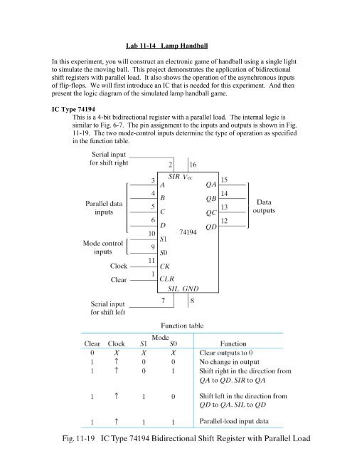
IC Type 74194<br />
This is a 4-bit bidirectional register with a parallel load. The internal logic is<br />
similar to Fig. 6-7. The pin assignment to the inputs <strong>an</strong>d outputs is shown in Fig.<br />
<strong>11</strong>-19. The two mode-control inputs determine the type of operation as specified<br />
in the function table.
Logic Diagram<br />
The logic diagram of the electronic lamp h<strong>an</strong>dball is shown in Fig. <strong>11</strong>-20. It<br />
consists of two 74194 Ics, a dual D flip-flop 7474 IC, <strong>an</strong>d three gate Ics: 7400,<br />
7404, <strong>an</strong>d 7408. The ball is simulated by a moving light that is shifted left or<br />
right through the bidirectional shift register. The rate at which the light moves is<br />
determined by the frequency of the clock. The circuit is first initialized with the<br />
reset switch. The start switch starts the game by placing the ball (<strong>an</strong> indicator<br />
lamp) at the extreme right. The player must press the pulser push button to start<br />
the ball moving to the left.
The single light shifts to the left until it reaches the leftmost position (the wall), at<br />
which time the ball returns to the player by reversing the direction of shift of the<br />
moving light. When the light is again at the rightmost position, the player must<br />
press the pulser again to reverse the direction of the shift. If the player presses the<br />
pulser too soon or too late, the ball disappears <strong>an</strong>d the light goes off. The game<br />
c<strong>an</strong> be restarted by turning the start switch on <strong>an</strong>d then off. The start switch must<br />
be open (logic-1) during the game.<br />
Circuit Analysis<br />
Prior to connecting the circuit, <strong>an</strong>alyze the logic diagram to ensure that <strong>you</strong><br />
underst<strong>an</strong>d how the circuit operates. <strong>In</strong> particular, try to <strong>an</strong>swer the following<br />
questions:<br />
1. What is the function of the reset switch<br />
2. Explain how the light in the rightmost position comes when the start switch is<br />
grounded. Why is it necessary to place the start switch in the logic-1 position<br />
before the game starts<br />
3. What happens to the two mode-control inputs, S1 <strong>an</strong>d S0, once the ball is set in<br />
motion<br />
4. What happens to the mode-control inputs <strong>an</strong>d to the ball if the pulser is pressed<br />
while the ball is moving to the left What happens if it is moving to the right <strong>an</strong>d<br />
has not yet reached the rightmost position yet<br />
5. Suppose that the ball returned to the rightmost position, but the pulser has not<br />
been pressed yet; what is the state of the mode-control inputs if the pulser is<br />
pressed What happens if it is not yet pressed<br />
Playing the Game<br />
Wire the circuit of Fig. <strong>11</strong>-20. Test the circuit for proper operation by playing the<br />
game. Note that the pulser must provide a positive-edge tr<strong>an</strong>sition <strong>an</strong>d that both<br />
the reset <strong>an</strong>d start switches must be open (be in the logic-1 state) during the game.<br />
Start with a low clock rate <strong>an</strong>d increase the clock frequency to make the h<strong>an</strong>dball<br />
game more challenging.<br />
Counting the Number of Losses<br />
Design a circuit that keeps score of the number of times the player loses while<br />
playing the game. Use a BCD-to-seven-segment decoder <strong>an</strong>d a seven-segment<br />
display as in Fig. <strong>11</strong>-8 to display the count from 0 through 9. Counting is done<br />
with a decimal counter using either the 7493 as a ripple decimal counter or the<br />
74161 <strong>an</strong>d a NAND gate as a synchronous decimal counter. The display should<br />
show 0 when the circuit is reset. Every time the ball disappears <strong>an</strong>d the light goes<br />
off, the display should increase by one. If the light stays on stays on during the<br />
play, the number in the display should not ch<strong>an</strong>ge. The final design should be <strong>an</strong><br />
automatic scoring circuit; with the decimal display incremented automatically<br />
each time the player loses when the light disappears.
<strong>Lamp</strong> Ping-Pong TM<br />
Modify the circuit of Fig. <strong>11</strong>-20 so as to obtain a lamp Ping-Pong game. Two<br />
players c<strong>an</strong> participate in <strong>this</strong> game, with each player having his own pulser. The<br />
player with the right pulser returns the ball when in the extreme right position,<br />
<strong>an</strong>d the player with the left pulser returns the ball when in the extreme left<br />
position. The only modification required for the Ping-Pong game is a second<br />
pulser <strong>an</strong>d a ch<strong>an</strong>ge of a few wires.