Fury Firmware Upgrade Instructions â rev. 1.1 (Fury2 software ...
Fury Firmware Upgrade Instructions â rev. 1.1 (Fury2 software ...
Fury Firmware Upgrade Instructions â rev. 1.1 (Fury2 software ...

Create successful ePaper yourself
Turn your PDF publications into a flip-book with our unique Google optimized e-Paper software.
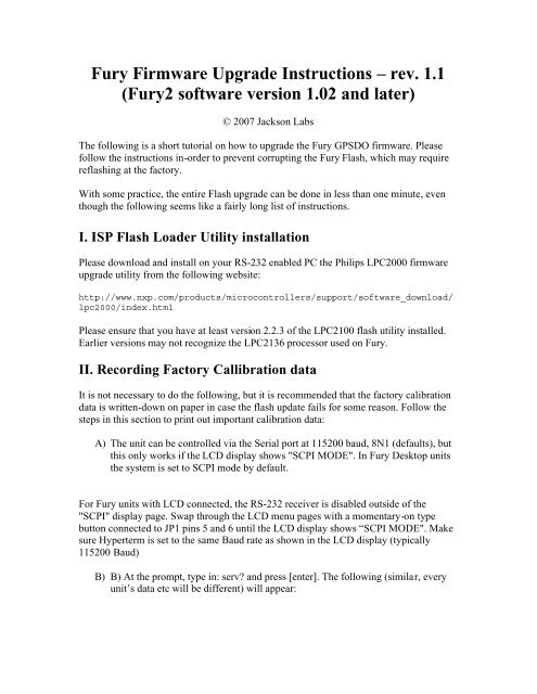
<strong>Fury</strong> <strong>Firmware</strong> <strong>Upgrade</strong> <strong>Instructions</strong> – <strong>rev</strong>. <strong>1.1</strong><br />
(<strong>Fury</strong>2 <strong>software</strong> version 1.02 and later)<br />
© 2007 Jackson Labs<br />
The following is a short tutorial on how to upgrade the <strong>Fury</strong> GPSDO firmware. Please<br />
follow the instructions in-order to p<strong>rev</strong>ent corrupting the <strong>Fury</strong> Flash, which may require<br />
reflashing at the factory.<br />
With some practice, the entire Flash upgrade can be done in less than one minute, even<br />
though the following seems like a fairly long list of instructions.<br />
I. ISP Flash Loader Utility installation<br />
Please download and install on your RS-232 enabled PC the Philips LPC2000 firmware<br />
upgrade utility from the following website:<br />
http://www.nxp.com/products/microcontrollers/support/<strong>software</strong>_download/<br />
lpc2000/index.html<br />
Please ensure that you have at least version 2.2.3 of the LPC2100 flash utility installed.<br />
Earlier versions may not recognize the LPC2136 processor used on <strong>Fury</strong>.<br />
II. Recording Factory Callibration data<br />
It is not necessary to do the following, but it is recommended that the factory calibration<br />
data is written-down on paper in case the flash update fails for some reason. Follow the<br />
steps in this section to print out important calibration data:<br />
A) The unit can be controlled via the Serial port at 115200 baud, 8N1 (defaults), but<br />
this only works if the LCD display shows "SCPI MODE". In <strong>Fury</strong> Desktop units<br />
the system is set to SCPI mode by default.<br />
For <strong>Fury</strong> units with LCD connected, the RS-232 receiver is disabled outside of the<br />
"SCPI" display page. Swap through the LCD menu pages with a momentary-on type<br />
button connected to JP1 pins 5 and 6 until the LCD display shows “SCPI MODE". Make<br />
sure Hyperterm is set to the same Baud rate as shown in the LCD display (typically<br />
115200 Baud)<br />
B) B) At the prompt, type in: serv and press [enter]. The following (similar, every<br />
unit’s data etc will be different) will appear:
[PLEASE NOTE THAT THE ABOVE VALUES ARE REPRESENTATIVE, AND<br />
SHOULD NOT BE ENTERED INTO YOUR FURY UNIT!]<br />
Note down the Coarse DAC, EFC Scale, EFC damping, OCXO slope, Temperature<br />
compensation (this value is quite important and varies from unit to unit!), aging<br />
compensation, and Phase correction parameters so these can be typed in later in case<br />
these original values are lost for some reason.
III. Preparing the Desktop Unit for <strong>software</strong> installation<br />
In order to upgrade the <strong>Fury</strong> firmware, the desktop enclosure has to be opened.<br />
First and most importantly, disconnect the <strong>Fury</strong> unit from AC mains power, or from any<br />
other power source you may have connected.<br />
Carefully remove the four screws on the faceplate (side with BNC connectors only) of the<br />
<strong>Fury</strong> units as shown in the following picture. Please note not to tighten the screws too<br />
much when re-assembling the unit, the screws may very easily strip the aluminum<br />
enclosures’ threads.<br />
Remove the four screws indicated by the red arrows:
IV. Turning the unit into In Circuit Programming (ISP) mode<br />
After removing the four screws as described in the p<strong>rev</strong>ious section., carefully pull-out<br />
the faceplate to about 1 inch in length until the Red Jumper JP3 (marked by the red arrow<br />
in the picture below) is visible.<br />
Using tweazers or very small plyers, move the jumper JP3 (next to RS232 connector)<br />
from position 1-2 to position 2-3. Be carefull not to touch the adjacent cables and<br />
connector pins with the tweazers or plyers.<br />
Push the PCB back into the enclosure making sure that the unit is fully closed. Re-apply<br />
power to the unit.<br />
Now press the RESET button or power cycle the unit. If the LED’s blink, the jumper<br />
JP3 has not been set correctly, and the unit is not in ISP mode.<br />
The unit has now been set to ISP mode, and is awaiting the firmware download.<br />
V. Downloading the firmware<br />
A) Close Hyperterm, and open the LPC2000 utility. Set the COM port in the<br />
LPC2000 application as needed on your PC.<br />
B) Press the “READ DEVICE ID” button, this should then show “LPC2136” in the<br />
DEVICE window if the unit is communicating correctly to the application.<br />
Make sure NOT(!!) to press the “erase” button under any circumstances, this may<br />
erase factory calibration data, and the unit will not operate and will have to be
eturned to the factory. Pressing the “erase” button on the ISP utility will thus void<br />
the warranty.<br />
Please note that the “Use Baud Rate” setting needs to be set to 38400 Baud or less, it<br />
will not work faster than 38400 Baud.<br />
Please note that the DEVICE should show “LPC2136”<br />
Also, please point the “Filename” to the directory where you have stored the firmware<br />
hex file that is to be downloaded.<br />
B) Start the download by pressing “Upload to Flash” button. The following window<br />
should appear if the correct COM port has been chosen etc:
Press the “OK” button, and the download should start. Sometimes the utility get’s<br />
confused and this process (from item V. B) has to be tried several times.<br />
Usually, it is not necessary to press “reset” as the utility is asking. Just press “OK” on the<br />
utility windows’ button.<br />
If you reset the unit, then please make sure that jumper JP3 is set to pins 2-3.<br />
DO NOT PRESS THE “ERASE” BUTTON AT ANY TIME! THIS WILL<br />
RENDER THE PCB USELESS AND CAN ONLY BE RECOVERED AT THE<br />
FACTORY!<br />
VI. Updating Parameters<br />
A) After the download has finished, remove power from the unit.<br />
B) Carefully pull out the PCB as described in section IV.<br />
C) Re-adjust jumper JP3 to pins 1-2. This will allow normal operation after a powercycle/reset.<br />
Please note that jumper JP3 has to be in the 1-2 position (moved in the direction of<br />
the adjacent faceplate) in order for the unit to operate normally!<br />
D) B) Close the LPC2000 utility, and restart hyperterm
E) Carefully push the PCB back into the enclosure, and add the screws to the<br />
enclosure, being careful not to strip the enclosures threads.<br />
F) C) Press the RESET button, or power-cycle the unit.<br />
The LED’s should blink, and/or the ALARM LED should light up.<br />
For units with LCD display, verify that the LCD is in the “SCPI MODE” page, and that<br />
the Baud rate shown in the LCD display matches the Hyperterm setting.<br />
During power on, the unit sends an ID string to Hyperterm. The firmware version can<br />
also be quereyed by sending the *IDN command. Verify that the firmware version is<br />
version 1.02 or above.<br />
VII. Entering the calibration parameters in case the Flash was<br />
corrupted for some reason.<br />
Type the command serv and compare the new settings to the old firmware’s settings<br />
noted down on paper p<strong>rev</strong>iously.<br />
Re-enter any settings that do not match the p<strong>rev</strong>ious settings of the older firmware.<br />
Type “help” to get instructions of how to enter the data into the “SERV” structure.<br />
Verify that all settings have been correctly entered by typing “serv” at the end of the<br />
data entry session.<br />
This concludes the firmware update procedure.<br />
__________________________<br />
VIII. Short command reference<br />
There are a number of commands that can be used, as listed below. Most of these are<br />
identical to Symmetricom 58503 commands; Jackson Labs added the following:<br />
SYNC:FEE<br />
This query returns the Frequency Error Estimate<br />
MEAS<br />
shows OCXO voltage, current etc.<br />
and others.<br />
Type "help" to get the complete list (please note that additional commands are<br />
added as the firmware matures):
help<br />
SERVo:COARSeDac [0,225]<br />
SERVo:EFCScale [0.0 , 500.0]<br />
SERVo:EFCDamping [0.0 , 4000.0]<br />
SERVo:SLOPe <br />
SERVo:TEMPCOmpensation [-1000.0, 1000.0]<br />
SERVo:PHASECOrrection [-100.0, 100.0]<br />
SERVo:1PPSoffset ns<br />
SERVo:QUIet <br />
(all <strong>Fury</strong> specific to tune the PID. In production, they should be set in<br />
Factory)<br />
SYNChronisation:HOLDover:DURation<br />
(From Symmetricom 58503 manual )<br />
This query returns the duration of the present or most recent period of<br />
operation in the holdover and holdover processes. This is the length of time<br />
the reference oscillator was not locked to GPS. The time units are seconds.<br />
Response The first number in the response is the holdover duration. The<br />
duration units are seconds, and the resolution is 1 second. If the Receiver<br />
is in holdover, the response quantifies the current holdover duration. If<br />
the Receiver is not in holdover, the response quantifies the p<strong>rev</strong>ious<br />
holdover. The second number in the response identifies the holdover state. A<br />
value of 0 indicates the Receiver is not in holdover; a value of 1 indicates<br />
the Receiver is in holdover. :SYNChronization:HOLDover:DURation RESPONSE<br />
FORMAT Returns the duration of the present or most recent period of<br />
operation in the holdover and holdover processes. ± d.dEe, 0 or 1<br />
SYNChronisation:TINTerval<br />
(similar to Symmetricom 58503 )<br />
This query returns the difference or timing shift between the <strong>Fury</strong> 1 PPS and<br />
the GPS 1 PPS signals.<br />
Resolution is 1E-10 seconds.<br />
SYNChronisation:IMMEdiate<br />
(From Symmetricom 58503 manual )<br />
:SYNChronization:IMMediate Initiates a near-instantaneous alignment of the<br />
GPS 1 PPS and Receiver output 1 PPS if the command is issued during recovery<br />
from holdover.<br />
SYNChronisation: :FEEstimate<br />
This query returns the Frequency Error Estimate<br />
DIAGnostic:ROCSillator:EFControl:RELative
(From Symmetricom 58503 manual )<br />
This query returns the Electronic Frequency Control (EFC) output value of<br />
the internal reference oscillator. It returns a percentage value.<br />
Response Range is -100% to +100%. :<br />
Currently the <strong>Fury</strong> returns a number between 0 and 100% but I will change it<br />
to be compatible to Symmetricom in next firware release<br />
GPS:INITial:DATE Used to set the GPS receivers initial<br />
date at start up<br />
:TIME Used to set the GPS receivers initial<br />
time at start up<br />
:POSition Set initial position<br />
(From Symmetricom 58503 manual )<br />
This command sets an approximate position for faster initial GPS<br />
acquisition. Following powerup, the Receiver refines its position from the<br />
satellite data. This process occurs automatically. This command is most<br />
effective when the retained position differs significantly from the Receiver<br />
s true position.<br />
GPS:REFerence:ADELay <br />
(From Symmetricom 58503 manual )<br />
:GPS:REFerence:ADELay Sets the GPS antenna delay value in seconds.<br />
:GPS:REFerence:ADELay Returns the GPS antenna delay value in seconds.<br />
GPS:REFerence:TRAIM ON | OFF Turms M12+ train on and off<br />
GPS:REFerence:TRAIM:RSVIDs<br />
(specific <strong>Fury</strong>)<br />
32 bit field to indicate which SVIDs were removed by TRAIM.<br />
This comes from the message @@Hn of Motorola M12+<br />
GPS:REFerence:PULse:SAWtooth<br />
(specific <strong>Fury</strong>)<br />
negative sawtooth time error of next 1 PPS coming from the GPS recevier<br />
( -128, +127 ns)<br />
This comes from the message @@Hn of Motorola M12+<br />
GPS:REFerence:PUlse:ACCuracy<br />
(specific <strong>Fury</strong>)<br />
Time solution 1 sigma accuracy estimate<br />
This comes from the message @@Hn of Motorola M12+<br />
GPS:REFerence:PULse<br />
(specific <strong>Fury</strong>)
Pulse status ( 0 or 1)<br />
This comes from the message @@Hn of Motorola M12+<br />
GPS:SATellite:TRACking:EMANgle [0,89] <br />
(From Symmetricom 58503 manual )<br />
:GPS:SATellite:TRACking:EMANgle Sets the GPS elevation mask angle<br />
value.<br />
:GPS:SATellite:TRACking:EMANgle Returns the GPS elevation mask angle value.<br />
GPS:SATellite:TRACking::COUNT<br />
(From Symmetricom 58503 manual )<br />
Returns a list of all satellites being tracked.<br />
GPS:SATellite::VISible:PREDicted:COUNT<br />
(From Symmetricom 58503 manual )<br />
Returns the number of satellites (PRN) that the almanac predicts should be<br />
visible, given date, time, and position.<br />
GPS:POSition <br />
(From Symmetricom 58503 manual )<br />
Specifies the position of the GPS antenna.<br />
GPS:POSition LAST<br />
(From Symmetricom 58503 manual )<br />
LAST denotes the last specified position. This parameter is provided to<br />
cancel surveying (automatic position computation) and restore the last<br />
position setting.<br />
GPS:POSition:HOLD:LAST<br />
(From Symmetricom 58503 manual )<br />
This query returns the last position-hold setting, which is restored when<br />
the :GPS:POSition LAST command is sent.<br />
GPS:POSition:SURVey:STATe ONCE<br />
(From Symmetricom 58503 manual )<br />
Set the GPS Receiver in Auto-Survey<br />
GPS:POSition:SURVey:STATe<br />
(From Symmetricom 58503 manual )<br />
Return (0 or 1) to specify if the GPS Receiver is in Auto-Survey or not<br />
MEASure:TEMPerature<br />
(specific <strong>Fury</strong>)<br />
This query returns the temperature of the sensor located next to the OCXO<br />
MEASure:VOLTage
(specific <strong>Fury</strong>)<br />
This query returns the voltage applied to the OCXO ( around 10.5 V )<br />
MEASure:CURRent<br />
(specific <strong>Fury</strong>)<br />
This query returns the current drawn by the OCXO. This current varies in<br />
order to keep a stable temperature inside the OCXO.<br />
PTIMe:TZONe [-12,12],[0,59]<br />
(From Symmetricom 58503 manual )<br />
Sets the time zone local time offset to provide an offset from UTC to serve<br />
as the basis for all reported time.<br />
:PTIMe:TZONe<br />
Returns the local time zone offset.<br />
PTIMe:DATE<br />
(From Symmetricom 58503 manual )<br />
This query returns the current calendar date. The local calendar date is<br />
always referenced to UTC time, offset by any local time zone value that has<br />
been provided by the user. The year, month, and day are returned.<br />
Response Three fields are separated by commas: ,,. " The<br />
range is 1994 to 2077. " The range is 1 to 12. " The <br />
range is 1 to 31.<br />
PTIMe:TIME<br />
(From Symmetricom 58503 manual )<br />
This query returns the current 24-hour time. The local time is always<br />
referenced to UTC time, offset by any local time zone value that has been<br />
provided by the user. The hour, minute, and second is returned.<br />
Response Three fields are separated by commas: ,,. "<br />
The range is 0 to 23. " The range is 0 to 59. " The <br />
range is 0 to 60. The value of 60 only occurs as the UTC leapsecond.<br />
PTIMe:TIME:STRing<br />
(From Symmetricom 58503 manual )<br />
This query returns the current 24-hour time suitable for display (for<br />
example, 14:22:34).<br />
PTIMe:LEAPsecond:PENDing<br />
This query identifies if a leap second is pending. This query looks ahead to<br />
indicate a pending leap second.<br />
Response A value of 0 indicates no leap second is pending. A value of 1<br />
indicates a leap second is pending.<br />
The leap second adjustment can be either the addition of a second or the<br />
subtraction of a second.
PTIMe:LEAPsecond:ACCumulated<br />
(From Symmetricom 58503 manual )<br />
Returns the leap second difference accumulated between GPS time and UTC time<br />
since the beginning of GPS time. The time units are seconds.<br />
PTIMe:LEAPsecond:DATE<br />
(From Symmetricom 58503 manual )<br />
Returns the date of the future the leap second ( usually UTC June 30 or<br />
UTC December 31)<br />
Note:<br />
But on my <strong>Fury</strong>, the GPS Motorola currently returns 2005,12,3 : I guess that<br />
it can return the date of last leap second<br />
PTIMe:LEAPsecond:DURation<br />
(From Symmetricom 58503 manual )<br />
This query identifies whether a leap second is pending, distinguishes<br />
between leap seconds which extend the minute, and leap seconds which shorten<br />
the minute. This query returns the duration of the minute corrected by the<br />
next leap second. The duration units are seconds. Response Returns a value<br />
of 59, 60 or 61: " A value of 59 indicates subtraction of 1 second is<br />
pending. " A value of 60 indicates no leap second pending. " A value of 61<br />
indicates addition of 1 second is pending. Returns the duration of the<br />
minute corrected by the next leap second. ± dd<br />
SYSTem:COMMunicate:SERial:ECHO <br />
Enable echo on RS-232<br />
SYSTem:COMMunicate:SERial:BAUD <br />
Setup RS-232 serial speed<br />
The serial configuration is always 8 bit , 1 stop bit, no parity, no Hw<br />
control<br />
QUIT<br />
HELP