ULN-1100 User Manual - Jackson Labs Technologies, Inc.
ULN-1100 User Manual - Jackson Labs Technologies, Inc.
ULN-1100 User Manual - Jackson Labs Technologies, Inc.

You also want an ePaper? Increase the reach of your titles
YUMPU automatically turns print PDFs into web optimized ePapers that Google loves.
<strong>ULN</strong>-<strong>1100</strong> <strong>User</strong><br />
<strong>Manual</strong><br />
Document: 80200502<br />
Version: 1.3<br />
Date: 29 March, 2012
<strong>ULN</strong>-<strong>1100</strong> <strong>User</strong> <strong>Manual</strong><br />
Copyright © 2010, 2011, 2012 <strong>Jackson</strong> <strong>Labs</strong> <strong>Technologies</strong>, <strong>Inc</strong>.
<strong>ULN</strong>-<strong>1100</strong> <strong>User</strong> <strong>Manual</strong><br />
1 Introduction . . . . . . . . . . . . . . . . . . . . . . . . . . . . . 1<br />
1.1 Overview . . . . . . . . . . . . . . . . . . . . . . . . . . . . . . . 1<br />
1.2 General Safety Precautions . . . . . . . . . . . . . . . . . . . . . . . . 1<br />
1.2.1 Grounding . . . . . . . . . . . . . . . . . . . . . . . . . . . . 1<br />
1.2.2 Power Connections. . . . . . . . . . . . . . . . . . . . . . . . . 1<br />
1.2.3 Environmental Conditions . . . . . . . . . . . . . . . . . . . . . . 1<br />
2 Quick-Start Instructions . . . . . . . . . . . . . . . . . . . . . . 5<br />
2.1 Powering Up the Unit . . . . . . . . . . . . . . . . . . . . . . . . . . 5<br />
2.1.1 Major connections . . . . . . . . . . . . . . . . . . . . . . . . . 5<br />
2.1.2 Power Harness Pinning . . . . . . . . . . . . . . . . . . . . . . . 9<br />
2.1.3 100MHz LVDS Harness Pinning. . . . . . . . . . . . . . . . . . . .10<br />
2.1.4 Harness Connectors . . . . . . . . . . . . . . . . . . . . . . . .10<br />
2.1.5 Coaxial Connectors. . . . . . . . . . . . . . . . . . . . . . . . .11<br />
2.1.6 Power . . . . . . . . . . . . . . . . . . . . . . . . . . . . . .11<br />
2.2 Connecting the GPS Antenna . . . . . . . . . . . . . . . . . . . . . . .11<br />
2.3 Remote serial control . . . . . . . . . . . . . . . . . . . . . . . . . .11<br />
2.3.1 “Help” and command overview . . . . . . . . . . . . . . . . . . . .12<br />
2.3.2 Loop parameter adjustment . . . . . . . . . . . . . . . . . . . . .12<br />
3 SCPI-Control Quick Start Instructions . . . . . . . . . . . . . .13<br />
3.1 Introduction . . . . . . . . . . . . . . . . . . . . . . . . . . . . . .13<br />
3.2 General SCPI Commands . . . . . . . . . . . . . . . . . . . . . . . .13<br />
3.2.1 *IDN . . . . . . . . . . . . . . . . . . . . . . . . . . . . . .13<br />
3.2.2 HELP. . . . . . . . . . . . . . . . . . . . . . . . . . . . . .13<br />
3.3 GPS Subsystem . . . . . . . . . . . . . . . . . . . . . . . . . . . .13<br />
3.3.1 GPS:SATellite. . . . . . . . . . . . . . . . . . . . . . . . . . .14<br />
3.3.2 GPS:SATellite:TRAcking:COUNt . . . . . . . . . . . . . . . . . . .14<br />
3.3.3 GPS:SATellite:VISible:COUNt . . . . . . . . . . . . . . . . . . . .14<br />
3.3.4 NMEA Support . . . . . . . . . . . . . . . . . . . . . . . . . .14<br />
3.3.5 GPS:GPGGA . . . . . . . . . . . . . . . . . . . . . . . . . . .15<br />
3.3.6 GPS:GGASTat . . . . . . . . . . . . . . . . . . . . . . . . . .15<br />
3.3.7 GPS:GPRMC . . . . . . . . . . . . . . . . . . . . . . . . . . .16<br />
3.3.8 GPS:XYZSPeed . . . . . . . . . . . . . . . . . . . . . . . . . .16<br />
3.3.9 GPS:GPZDA . . . . . . . . . . . . . . . . . . . . . . . . . . .16<br />
3.3.10GPS:PASHR . . . . . . . . . . . . . . . . . . . . . . . . . . .17<br />
3.3.11GPS:GYRO . . . . . . . . . . . . . . . . . . . . . . . . . . .18<br />
3.3.12GPS:GYRO:CAL . . . . . . . . . . . . . . . . . . . . . . . . .18<br />
3.3.13GPS:DYNAMic . . . . . . . . . . . . . . . . . . . . . . . . . .19<br />
3.3.14GPS:DYNAMic 8 (Automatic Dynamic Mode) . . . . . . . . . . . . . .20<br />
3.3.15GPS:REFerence:ADELay [-32767ns,32767ns] . . . . . . .21<br />
3.3.16GPS:REFerence:PULse:SAWtooth . . . . . . . . . . . . . . . . . .21<br />
3.3.17GPS:RESET ONCE . . . . . . . . . . . . . . . . . . . . . . . .21<br />
3.3.18GPS:INITial:DATE . . . . . . . . . . . . . . . . . . .22<br />
3.3.19GPS:INITial:TIME . . . . . . . . . . . . . . . . . . .22<br />
3.3.20GPS:JAMlevel . . . . . . . . . . . . . . . . . . . . . . . . . .22<br />
3.3.21GPS . . . . . . . . . . . . . . . . . . . . . . . . . . . . . .22<br />
3.4 GYRO SUBSYSTEM . . . . . . . . . . . . . . . . . . . . . . . . . .22<br />
3.4.1 GYRO:MODE . . . . . . . . . . . . . . . . . . . . . .23<br />
3.4.2 GYRO:TRACE [0,255] . . . . . . . . . . . . . . . . . . . . .23<br />
© 2012 <strong>Jackson</strong> <strong>Labs</strong> <strong>Technologies</strong>, <strong>Inc</strong>. iii
<strong>ULN</strong>-<strong>1100</strong> <strong>User</strong> <strong>Manual</strong><br />
3.4.3 GYRO:CAL . . . . . . . . . . . . . . . 23<br />
3.4.4 GYRO:CAL:COMPUTE. . . . . . . . . . . . . . . . . . . . . . . 23<br />
3.4.5 GYRO:SENS, GYRO:EFC, and GPS:CAL:RESET . . . . . . . . . . . . 23<br />
3.4.6 GYRO:GLOAD . . . . . . . . . . . . . . . . . . . . . . . . . 23<br />
3.5 PTIME Subsystem . . . . . . . . . . . . . . . . . . . . . . . . . . . 23<br />
3.5.1 PTIMe:TZONe . . . . . . . . . . . . . . . . . . . . . . . . . . 24<br />
3.5.2 PTIMe:DATE . . . . . . . . . . . . . . . . . . . . . . . . . . 24<br />
3.5.3 PTIMe:TIME . . . . . . . . . . . . . . . . . . . . . . . . . . 24<br />
3.5.4 PTIMe:TIME:STRing . . . . . . . . . . . . . . . . . . . . . . . 24<br />
3.5.5 PTIMe:TINTerval . . . . . . . . . . . . . . . . . . . . . . . . . 24<br />
3.5.6 PTIME . . . . . . . . . . . . . . . . . . . . . . . . . . . . . 24<br />
3.6 SYNChronization Subsystem . . . . . . . . . . . . . . . . . . . . . . . 24<br />
3.6.1 SYNChronization:HOLDover:DURation . . . . . . . . . . . . . . . . 25<br />
3.6.2 SYNChronization:HOLDover:INITiate . . . . . . . . . . . . . . . . . 25<br />
3.6.3 SYNChronization:HOLDover:RECovery:INITiate . . . . . . . . . . . . . 25<br />
3.6.4 SYNChronization:SOURce:MODE . . . . . . . . . . . . . . . . . . 25<br />
3.6.5 SYNChronization:SOURce:STATE . . . . . . . . . . . . . . . . . . 26<br />
3.6.6 SYNChronization:TINTerval . . . . . . . . . . . . . . . . . . . . 26<br />
3.6.7 SYNChronization:IMMEdiate. . . . . . . . . . . . . . . . . . . . . 26<br />
3.6.8 SYNChronization:FEEstimate . . . . . . . . . . . . . . . . . . . . 26<br />
3.6.9 SYNChronization:LOCKed . . . . . . . . . . . . . . . . . . . . . 26<br />
3.6.10SYNChronization:OUTput:1PPS:RESET [ON|OFF] . . . . . . . . . . . 26<br />
3.6.11SYNChronization:health . . . . . . . . . . . . . . . . . . . . . . 26<br />
3.6.12SYNChronization. . . . . . . . . . . . . . . . . . . . . . . . . 27<br />
3.7 DIAGnostic Subsystem . . . . . . . . . . . . . . . . . . . . . . . . . 28<br />
3.7.1 DIAGnostic:ROSCillator:EFControl:RELative . . . . . . . . . . . . . . 28<br />
3.7.2 DIAGnostic:ROSCillator:EFControl:ABSolute . . . . . . . . . . . . . . 28<br />
3.8 MEASURE Subsystem . . . . . . . . . . . . . . . . . . . . . . . . . 28<br />
3.8.1 MEASure:VOLTage. . . . . . . . . . . . . . . . . . . . . . . . 28<br />
3.8.2 MEASure:CURRent. . . . . . . . . . . . . . . . . . . . . . . . 28<br />
3.8.3 MEASure . . . . . . . . . . . . . . . . . . . . . . . . . . . . 28<br />
3.9 SYSTEM Subsystem . . . . . . . . . . . . . . . . . . . . . . . . . . 29<br />
3.9.1 SYSTem:COMMunicate . . . . . . . . . . . . . . . . . . . . . . 29<br />
3.9.1.1 SYSTem:COMMunicate:SERial:ECHO . . . . . . . . . . . . . 29<br />
3.9.1.2 SYSTem:COMMunicate:SERial:PROmpt . . . . . . . . . . . . 29<br />
3.9.1.3 SYSTem:COMMunicate:SERial:BAUD . . . . . . . . . . . . . 29<br />
3.9.2 SYSTem:STATus . . . . . . . . . . . . . . . . . . . . . . . . 29<br />
3.9.3 SYSTem:FACToryReset ONCE . . . . . . . . . . . . . . . . . . . 29<br />
3.10SERVO Subsystem . . . . . . . . . . . . . . . . . . . . . . . . . . 29<br />
3.10.1SERVo:FASTlock . . . . . . . . . . . . . . . . . . . . . . . . . 30<br />
3.10.2SERVo:FALEngth . . . . . . . . . . . . . . . . . . . . . . . . . 31<br />
3.10.3SERVo:COARSeDac . . . . . . . . . . . . . . . . . . . . . . . 31<br />
3.10.4SERVo:DACGain . . . . . . . . . . . . . . . . . . . . . . . . . 31<br />
3.10.5SERVo: EFCScale . . . . . . . . . . . . . . . . . . . . . . . . 31<br />
3.10.6SERVo:EFCDamping . . . . . . . . . . . . . . . . . . . . . . . 32<br />
3.10.7SERVo:SLOPe . . . . . . . . . . . . . . . . . . . . . . . . . . 32<br />
3.10.8SERVo:TEMPCOmpensation . . . . . . . . . . . . . . . . . . . . 32<br />
3.10.9SERVo:AGINGcompensation . . . . . . . . . . . . . . . . . . . . 32<br />
3.10.10SERVo:PHASECOrrection . . . . . . . . . . . . . . . . . . . . . 32<br />
3.10.11SERVo:1PPSoffset . . . . . . . . . . . . . . . . . . . . . . . . 32<br />
3.10.12SERVo:TRACe . . . . . . . . . . . . . . . . . . . . . . . . . 32<br />
3.10.13SERVo . . . . . . . . . . . . . . . . . . . . . . . . . . . . 33<br />
iv<br />
© 2012 <strong>Jackson</strong> <strong>Labs</strong> <strong>Technologies</strong>, <strong>Inc</strong>.
<strong>ULN</strong>-<strong>1100</strong> <strong>User</strong> <strong>Manual</strong><br />
4 Firmware Upgrade Instructions . . . . . . . . . . . . . . . . . .35<br />
4.1 Introduction . . . . . . . . . . . . . . . . . . . . . . . . . . . . . .35<br />
4.2 ISP Flash Loader Utility installation . . . . . . . . . . . . . . . . . . . . .35<br />
4.2.1 Philips LPC2000 Flash Utility . . . . . . . . . . . . . . . . . . . . .35<br />
4.2.2 Flash Magic Flash Programming Utility . . . . . . . . . . . . . . . . .35<br />
4.3 Putting the PCB into In-Circuit Programming (ISP) mode . . . . . . . . . . . .36<br />
4.4 Downloading the firmware . . . . . . . . . . . . . . . . . . . . . . . .36<br />
4.4.1 Philips LPC2000 Flash Utility . . . . . . . . . . . . . . . . . . . . .36<br />
4.4.2 Flash Magic Flash Programming Utility . . . . . . . . . . . . . . . . .38<br />
4.5 Verifying Firmware Update . . . . . . . . . . . . . . . . . . . . . . . .41<br />
5 GPSCon Utility . . . . . . . . . . . . . . . . . . . . . . . . . . .43<br />
5.1 Description . . . . . . . . . . . . . . . . . . . . . . . . . . . . . .43<br />
5.2 Installation . . . . . . . . . . . . . . . . . . . . . . . . . . . . . .43<br />
5.3 Using GPSCon . . . . . . . . . . . . . . . . . . . . . . . . . . . . .43<br />
5.3.1 Setting the options . . . . . . . . . . . . . . . . . . . . . . . . .43<br />
5.3.1.1 Communication Parameters . . . . . . . . . . . . . . . . . .44<br />
5.3.1.2 Auxiliary parameters . . . . . . . . . . . . . . . . . . . . .44<br />
5.3.1.3 Other options . . . . . . . . . . . . . . . . . . . . . . . .46<br />
5.3.2 Sending manual commands to the receiver . . . . . . . . . . . . . . .46<br />
5.3.3 Use of the mouse in graph mode . . . . . . . . . . . . . . . . . . .47<br />
5.3.4 Exporting the graphics . . . . . . . . . . . . . . . . . . . . . . .49<br />
5.4 Interpreting the Data. . . . . . . . . . . . . . . . . . . . . . . . . . .50<br />
6 Certification and Warranty . . . . . . . . . . . . . . . . . . . . .51<br />
6.1 Certification . . . . . . . . . . . . . . . . . . . . . . . . . . . . . .51<br />
6.1.1 Warranty . . . . . . . . . . . . . . . . . . . . . . . . . . . . .51<br />
6.1.2 Limitation of Warranty . . . . . . . . . . . . . . . . . . . . . . . .51<br />
6.1.3 Exclusive Remedies . . . . . . . . . . . . . . . . . . . . . . . .52<br />
© 2012 <strong>Jackson</strong> <strong>Labs</strong> <strong>Technologies</strong>, <strong>Inc</strong>. v
<strong>ULN</strong>-<strong>1100</strong> <strong>User</strong> <strong>Manual</strong><br />
vi<br />
© 2012 <strong>Jackson</strong> <strong>Labs</strong> <strong>Technologies</strong>, <strong>Inc</strong>.
<strong>ULN</strong>-<strong>1100</strong> <strong>User</strong> <strong>Manual</strong><br />
1Introduction<br />
1.1 Overview<br />
The <strong>ULN</strong>-<strong>1100</strong> GPSDO includes an extremely high-performance GPS receiver that can acquire and<br />
track up to 50 GPS signals down to a state of the art –160dBm, a 32bit processor that runs a Real<br />
Time OS, four 100MHz LVDS outputs, one 100MHz CMOS output, two 100MHz Sine Wave<br />
outputs, one 10MHz sine wave output, 1PPS UTC synchronized LVDS and RS-232 outputs, RS-232<br />
control interface, and precision voltage references and DACs.<br />
1.2 General Safety Precautions<br />
The following general safety precautions must be observed during all phases of operation of this<br />
instrument. Failure to comply with these precautions or with specific warnings elsewhere in this<br />
manual violates safety standards of design manufacture, and intended use of the instrument. <strong>Jackson</strong><br />
<strong>Labs</strong> <strong>Technologies</strong>, <strong>Inc</strong>. assumes no liability for the customer’s failure to comply with these<br />
requirements.<br />
1.2.1 Grounding<br />
To avoid damaging the sensitive electronic components in the <strong>ULN</strong>-<strong>1100</strong> GSPDO always make sure<br />
to discharge any built-up electrostatic charge to a good ground source, such as power supply ground.<br />
This should be done before handling the circuit board or anything connected to it, i.e. the GPS<br />
antenna.<br />
1.2.2 Power Connections<br />
Make sure to connect the DC power to the device following the polarity indicated in Section 2.1 . Do<br />
not reverse the power pins as this will cause serious damage to the circuit board.<br />
1.2.3 Environmental Conditions<br />
This instrument is intended for indoor use. It is designed to operate at a maximum relative<br />
non-condensing humidity of 95% and at altitudes of up to 50,000 meters. Refer to the specifications<br />
tables for the ac mains voltage requirements and ambient operating temperature range.<br />
© 2012 <strong>Jackson</strong> <strong>Labs</strong> <strong>Technologies</strong>, <strong>Inc</strong>. 1
<strong>ULN</strong>-<strong>1100</strong> <strong>User</strong> <strong>Manual</strong><br />
2 © 2012 <strong>Jackson</strong> <strong>Labs</strong> <strong>Technologies</strong>, <strong>Inc</strong>.
<strong>ULN</strong>-<strong>1100</strong> <strong>User</strong> <strong>Manual</strong><br />
2Quick-Start<br />
Instructions<br />
2.1 Powering Up the Unit<br />
To operate the unit, simply do the following two steps:<br />
1) Connect a 5V-compatible GPS antenna to connector J2.<br />
2) Connect +12V DC Power to pins 15, and 16 of power connector U3, ground to pins 12 and<br />
14 of U3.<br />
The unit will now lock to GPS (Red LED is blinking when satellites are being received) and will<br />
indicate proper lock when the Green LED goes on. Once the green LED is on, the unit will output<br />
10MHz and 100MHz on the various outputs with significantly better than 1ppb frequency accuracy.<br />
Please note that the GPS receiver establishes the internal antenna gain right after power-on, so for<br />
proper operation the GPS antenna should always be connected prior to turning on the +12V power.<br />
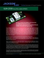
2.1.1 Major connections<br />
The major connections and features of the <strong>ULN</strong>-<strong>1100</strong> PCB are shown in Figure 2.1.<br />
© 2012 <strong>Jackson</strong> <strong>Labs</strong> <strong>Technologies</strong>, <strong>Inc</strong>. 5
<strong>ULN</strong>-<strong>1100</strong> <strong>User</strong> <strong>Manual</strong><br />
Figure 2.1<br />
Major connections<br />
GPS<br />
Antenna<br />
10MHz Sine Wave<br />
Output<br />
Power and I/O<br />
Connector<br />
Lock/1PPS LED<br />
100MHz CMOS<br />
ISP Reset<br />
Jumper<br />
100MHz LVDS<br />
Outputs (4x)<br />
100MHZ Sine<br />
Table 2.1 shows the <strong>ULN</strong>-<strong>1100</strong> revision 1.0 hardware connectors<br />
Table 2.1 <strong>ULN</strong>-<strong>1100</strong> hardware connectors<br />
Ref Name Function<br />
Specification<br />
Pinning<br />
J2 Antenna GPS Antenna 5V Amplified Antenna MMCX<br />
connector<br />
J1 ISP/RESET Reset and ISP Pull pins 1 and 3 to GND to<br />
activate function<br />
Center-RF Input, Shield-GND<br />
3-RESET-IN#, 2-GND, 1-ENTER_ISP#<br />
J3 10MHz Sine Out 10MHz Sine Wave Out +13dBm +/-3dB 50Ohms Center-RF, Shield-GND<br />
J4 100MHz Sine 100MHz Sine Wave +7dBm +/-3dB 50Ohms Center-RF, Shield-GND<br />
J6 100MHz Sine 100MHz Sine Wave +7dBm +/-3dB 50Ohms Center-RF, Shield-GND<br />
J5 100MHz CMOS 100MHz CMOS Out +3.3V CMOS,
<strong>ULN</strong>-<strong>1100</strong> <strong>User</strong> <strong>Manual</strong><br />
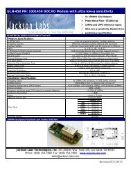
Warning:<br />
PLEASE NOTE THAT THE POWER AND LVDS CONNECTORS U3 AND U25 USE<br />
THE SAME CONNECTOR TYPE. PLUGGING A POWER CONNECTOR INTO THE<br />
LVDS CONNECTOR U25 BY ACCIDENT WILL DAMAGE THE BOARD AND<br />
CARE SHOULD BE TAKEN TO AVOID PLUGGING IN THE POWER CABLE<br />
HARNESS INTO THE LVDS CONNECTOR U25.<br />
Figure 2.2<br />
Typical Connections to Power Connector U3<br />
© 2012 <strong>Jackson</strong> <strong>Labs</strong> <strong>Technologies</strong>, <strong>Inc</strong>. 7
<strong>ULN</strong>-<strong>1100</strong> <strong>User</strong> <strong>Manual</strong><br />
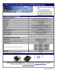
Figure 2.3 Typical Connections to the 100MHz LVDS Connector U25:<br />
8 © 2012 <strong>Jackson</strong> <strong>Labs</strong> <strong>Technologies</strong>, <strong>Inc</strong>.
<strong>ULN</strong>-<strong>1100</strong> <strong>User</strong> <strong>Manual</strong><br />
2.1.2 Power Harness Pinning<br />
Table 2.2 Power cable harness U3 pinout<br />
PIN<br />
NAME<br />
1 +10MHz LVDS<br />
2 –10MHz LVDS<br />
3 GND<br />
4 –1PPS LVDS<br />
5 +1PPS LVDS<br />
6 GND<br />
7 LOCK_OK_OUT<br />
8 RX RS-232<br />
9 TX RS-232<br />
10 1PPS Out RS-232 Level<br />
11 1PPS In CMOS level<br />
12 GND<br />
13 1PPS CMOS 5V<br />
14 GND<br />
15 +12V<br />
16 +12V<br />
© 2012 <strong>Jackson</strong> <strong>Labs</strong> <strong>Technologies</strong>, <strong>Inc</strong>. 9
<strong>ULN</strong>-<strong>1100</strong> <strong>User</strong> <strong>Manual</strong><br />
2.1.3 100MHz LVDS Harness Pinning<br />
PIN<br />
Table 2.3 100MHz LVDS cable harness U3 pinout<br />
NAME<br />
1 -DOUT1<br />
2 +DOUT1<br />
3 GND<br />
4 GND<br />
5 +DOUT2<br />
6 -DOUT2<br />
7 GND<br />
8 GND<br />
9 -DOUT3<br />
10 +DOUT3<br />
11 GND<br />
12 GND<br />
13 -DOUT4<br />
14 +DOUT4<br />
15 GND<br />
16 GND<br />
2.1.4 Harness Connectors<br />
The manufacturer for connectors U3 and U25 is Hirose. A mating housing part number for these<br />
connectors is available from Digikey, and crimp pins are also available from Digikey for different<br />
wire sizes:<br />
http://search.digikey.com/scripts/DkSearch/dksus.dllDetail&name=H2025-ND<br />
The part number of the connectors soldered onto the <strong>ULN</strong>-<strong>1100</strong> PCB is:<br />
Hirose DF11-16DP-2DSA01<br />
NOTES:<br />
• The LVDS signals (+/-10MHz, +/-100MHz, +/-1PPS) should be routed using 100Ohm differential<br />
wiring (twisted pair), or two 50Ohm single-ended coaxial cables with the shields being connected<br />
10 © 2012 <strong>Jackson</strong> <strong>Labs</strong> <strong>Technologies</strong>, <strong>Inc</strong>.
<strong>ULN</strong>-<strong>1100</strong> <strong>User</strong> <strong>Manual</strong><br />
to ground. Terminate these signals with 100 Ohm resistors between the positive and the negative<br />
wires.<br />
• The LOCK_OK_OUT signal is a 3.3V CMOS signals, and thus require a series resistor of<br />
typically 390 to 470 Ohms when used to drive LED’s.<br />
• The 10/100MHz 50 Ohm Sine Wave outputs (+13dBm) and CMOS outputs do not require a<br />
termination if they remain unused.<br />
2.1.5 Coaxial Connectors<br />
All five of the coaxial connectors on the <strong>ULN</strong>-<strong>1100</strong> board, J2, J3, J4, J5, J6 are generic MMCX type<br />
connectors.<br />
2.1.6 Power<br />
The unit is powered from a +11.0V to +14.0V DC source, with +12.0V nominal voltage. The current<br />
is typically less than 0.35A at 12V. Connect a clean +12V power supply to pins 15 and 16 of the cable<br />
harness U3.<br />
Warning:<br />
Do not reverse the polarity of the power pins, this will damage the unit.<br />
2.2 Connecting the GPS Antenna<br />
Connect the GPS antenna to the BNC to MMCX cable adapter. Caution: use a Lightning Arrestor on<br />
your Antenna setup. Use an amplified GPS antenna that is 5V LNA compatible. The <strong>ULN</strong>-<strong>1100</strong> GPS<br />
receiver is a 50 channel high-sensitivity GPS receiver with very fast lock time. It does not require any<br />
self-survey or position-hold mode (auto survey), and thus can be used in mobile platforms.<br />
Please note that the <strong>ULN</strong>-<strong>1100</strong> unit supports 5V active, or passive antennae.<br />
<strong>ULN</strong>-<strong>1100</strong> is capable of generating standard navigation messages (see GPS:GPGGA, GPS:GPZDA,<br />
and GPS:GPRMC RS-232 commands) that are compatible with most GPS based navigation<br />
software.<br />
The GPS receiver generates a 1PPS time signal that is phase synchronized to UTC. This 1PPS signal<br />
is used to frequency-lock the 10MHz Sine-Wave output of the <strong>ULN</strong>-<strong>1100</strong> GPSDO to UTC, thus<br />
disciplining the unit’s 10MHz frequency output to the US Naval master clock for very high<br />
frequency accuracy (typically better than 10 digits of frequency accuracy when locked to GPS).<br />
2.3 Remote serial control<br />
• The unit is controlled via the Serial port at 115200 baud, 8N1. Other Baud Rates can be set via<br />
SCPI commands.<br />
Connect the RX, TX, and GND pins of the cable harness U3 to a standard RS-232 connector.<br />
Attach the <strong>ULN</strong>-<strong>1100</strong> unit to your PC’s Hyperterminal, the optional GPSCon software package, or a<br />
third-party freeware Windows-based application program called Z38xx.<br />
The Z38xx program can be used to track the performance of the <strong>ULN</strong>-<strong>1100</strong>. Z38xx is available on<br />
the <strong>Jackson</strong> <strong>Labs</strong> <strong>Technologies</strong>, <strong>Inc</strong>. website under the following URL:<br />
© 2012 <strong>Jackson</strong> <strong>Labs</strong> <strong>Technologies</strong>, <strong>Inc</strong>. 11
<strong>ULN</strong>-<strong>1100</strong> <strong>User</strong> <strong>Manual</strong><br />
http://www.jackson-labs.com/assets/uploads/main/Z38XX.zip<br />
• An RS-232 level shifter is built into the <strong>ULN</strong>-<strong>1100</strong> PCB.<br />
2.3.1 “Help” and command overview<br />
• A listing of the available RS-232 commands can be shown by typing "help"<br />
• "*IDN" can be used to see if the connection works. Both commands need to be followed by<br />
pressing “Enter”<br />
2.3.2 Loop parameter adjustment<br />
• All loop parameters can be controlled via the RS-232 serial port.<br />
• Loop parameters are optimized for the OCXO on the board, and changing the factory settings may<br />
result in the unit’s performance to deteriorate.<br />
The commands to control the loop parameters are part of the servo command. See also the SERVO<br />
Subsystem section below.<br />
The individual commands are:<br />
EFC Scale: this is the proportional gain of the PID loop. Higher values will give quicker<br />
convergence, and faster locking of the GPS time (lower loop time constant), lower values give less<br />
noise. Values between 0.7 (good double oven OCXO) and 6.0 (simple single-oven OCXO) are<br />
typical.<br />
EFC Damping: overall IIR filter time constant. higher values increase loop time<br />
constant. <strong>Jackson</strong> <strong>Labs</strong> <strong>Technologies</strong>, <strong>Inc</strong>. typically uses values between 10 to 50. Setting this value<br />
too high may cause loop instability.<br />
Phase compensation: this is the Integral part of the PID loop. This corrects phase offsets between<br />
the <strong>ULN</strong>-<strong>1100</strong> 1PPS signal and the UTC 1PPS signal as generated by the GPS receiver. Set higher<br />
values for tighter phase-following at the expense of frequency stability. Typical values range from 4<br />
- 30, 25 being the default. Setting this value too high may cause loop instability.<br />
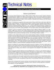
A well-compensated unit will show performance similar to the plot shown in Figure 2.4 when<br />
experiencing small perturbations:<br />
12 © 2012 <strong>Jackson</strong> <strong>Labs</strong> <strong>Technologies</strong>, <strong>Inc</strong>.
<strong>ULN</strong>-<strong>1100</strong> <strong>User</strong> <strong>Manual</strong><br />
Figure 2.4<br />
<strong>ULN</strong>-<strong>1100</strong> phase compensation plot<br />
© 2012 <strong>Jackson</strong> <strong>Labs</strong> <strong>Technologies</strong>, <strong>Inc</strong>. 13
<strong>ULN</strong>-<strong>1100</strong> <strong>User</strong> <strong>Manual</strong><br />
14 © 2012 <strong>Jackson</strong> <strong>Labs</strong> <strong>Technologies</strong>, <strong>Inc</strong>.
<strong>ULN</strong>-<strong>1100</strong> <strong>User</strong> <strong>Manual</strong><br />
3SCPI-Control Quick<br />
Start Instructions<br />
3.1 Introduction<br />
The SCPI (Standard Commands for Programmable Instrumentation) subsystem is accessed via the<br />
RS-232 interface and a terminal program. By default the terminal settings are 115200, 8N1.<br />
There are a number of commands that can be used as listed below. Most of these are identical or<br />
similar to Symmetricom 58503A commands. To get a listing of the available commands, send the<br />
HELP query. This will return a list of all the available commands for the <strong>ULN</strong>-<strong>1100</strong> GPSDO.<br />
Additional information regarding the SCPI protocol syntax can be found on the following web site:<br />
http://www.scpiconsortium.org<br />
Please refer to the document SCPI-99.pdf for details regarding individual SCPI command<br />
definitions. A basic familiarity with the SCPI protocol is recommended when reading this chapter.<br />
3.2 General SCPI Commands<br />
3.2.1 *IDN<br />
This query outputs an identifying string. The response will show the following information:<br />
, , , <br />
3.2.2 HELP<br />
This query returns a list of the commands available for the <strong>ULN</strong>-<strong>1100</strong> GPSDO.<br />
3.3 GPS Subsystem<br />
Note: Please note that <strong>ULN</strong>-<strong>1100</strong> displays antenna height in MSL Meters rather than in GPS Meters<br />
on all commands that return antenna height [the legacy Fury GPSDO uses GPS height]. The NMEA<br />
© 2012 <strong>Jackson</strong> <strong>Labs</strong> <strong>Technologies</strong>, <strong>Inc</strong>. 13
<strong>ULN</strong>-<strong>1100</strong> <strong>User</strong> <strong>Manual</strong><br />
position fixes are in the WGS84 coordinate system, while the X,Y, and Z velocity vectors are given in<br />
the ECEF coordinate system.<br />
The GPS subsystem regroups all the commands related to the control and status of the GPS receiver.<br />
The list of the commands supported is the following:<br />
GPS:SATellite:TRAcking:COUNt<br />
GPS:SATellite:VISible:COUNt<br />
GPS:GPGGA [0,255]<br />
GPS:GGASTat [0,255]<br />
GPS:GPRMC [0,255]<br />
GPS:GPZDA [0,255]<br />
GPS:PASHR [0,255]<br />
GPS:GYRO<br />
GPS:GYRO:CAL<br />
GPS:DYNAMic [0,7]<br />
GPS:INITial:DATE <br />
GPS:INITial:TIME <br />
GPS:JAMlevel<br />
GPS<br />
GPS:REFerence:ADELay [-32767ns,32767ns]<br />
GPS:REFerence:PULse:SAWtooth<br />
GPS:RESET ONCE<br />
3.3.1 GPS:SATellite<br />
This group of commands describe the satellite constellation.<br />
3.3.2 GPS:SATellite:TRAcking:COUNt<br />
This query returns the number of satellites being tracked.<br />
3.3.3 GPS:SATellite:VISible:COUNt<br />
This query returns the number of satellites (PRN) that the almanac predicts should be visible, given<br />
date, time, and position.<br />
3.3.4 NMEA Support<br />
The following four commands allow the <strong>ULN</strong>-<strong>1100</strong> GPSDO to be used as an industry standard<br />
navigation GPS receiver. The GPGGA, GPRMC, PASHR and GPZDA NMEA commands comprise<br />
14 © 2012 <strong>Jackson</strong> <strong>Labs</strong> <strong>Technologies</strong>, <strong>Inc</strong>.
<strong>ULN</strong>-<strong>1100</strong> <strong>User</strong> <strong>Manual</strong><br />
all necessary information about the antenna position, height, velocity, direction, satellite info, fix<br />
info, time, date and other information that can be used by standard navigation applications via the<br />
<strong>ULN</strong>-<strong>1100</strong> RS-232 interface.<br />
Once enabled, <strong>ULN</strong>-<strong>1100</strong> will send out information on the RS-232 transmit pin automatically every<br />
N seconds. All incoming RS-232 commands are still recognized by <strong>ULN</strong>-<strong>1100</strong> since the RS-232<br />
interface transmit and receive lines are completely independent of one another.<br />
Please note that the position, direction, and speed data is delayed by one second from when the GPS<br />
receiver internally reported these to the <strong>ULN</strong>-<strong>1100</strong> Microprocessor, so the position is valid for the<br />
1PPS pulse previous to the last 1PPS pulse at the time the data is sent (one second delay). The time<br />
and date are properly output with correct UTC synchronization to the 1PPS pulse immediately prior<br />
to the data being sent.<br />
Once set, the following two commands will be stored in NV memory, and generate output<br />
information even after power to the unit has been cycled.<br />
3.3.5 GPS:GPGGA<br />
This command instructs the <strong>ULN</strong>-<strong>1100</strong> to send the NMEA standard string $GPGGA every N<br />
seconds, with N in the interval [0,255]. The command is disabled during the initial 7 minute OCXO<br />
warm-up phase.<br />
This command has the following format:<br />
GPS:GPGGA [0,255]<br />
GPGGA shows height in MSL Meters, this is different from traditional GPS receivers that display<br />
height in GPS Meters. The difference between MSL and GPS height can be significant, 35m or more<br />
are common.<br />
3.3.6 GPS:GGASTat<br />
This command instructs the <strong>ULN</strong>-<strong>1100</strong> to send a modified version of the NMEA standard string<br />
$GPGGA every N seconds, with N in the interval [0,255]. The command is disabled during the initial<br />
7 minute OCXO warm-up phase.<br />
This command has the following format:<br />
GPS:GGASTat [0,255]<br />
This command replaces the regular NMEA GGA validity flag with a decimal number indicating the<br />
lock-state of the unit. Please see section SERVo:TRACe for a detailed description of the lock state<br />
variable. The command allows capture of the position and other information available in the GGA<br />
command, as well as tracking the lock state and health of the unit’s OCXO performance.<br />
© 2012 <strong>Jackson</strong> <strong>Labs</strong> <strong>Technologies</strong>, <strong>Inc</strong>. 15
<strong>ULN</strong>-<strong>1100</strong> <strong>User</strong> <strong>Manual</strong><br />
GGASTat shows height in MSL Meters, this is different from traditional GPS receivers that display<br />
height in GPS Meters. The difference between MSL and GPS height can be significant, 35m or more<br />
are common.<br />
3.3.7 GPS:GPRMC<br />
This command instructs the <strong>ULN</strong>-<strong>1100</strong> to send the NMEA standard string $GPRMC every N<br />
seconds, with N in the interval [0,255]. The command is disabled during the initial 7 minute OCXO<br />
warm-up phase.<br />
This command has the following format:<br />
GPS:GPRMC [0,255]<br />
3.3.8 GPS:XYZSPeed<br />
This command is a 3D velocity vector output command. Enabling this command will output a 3<br />
dimensional velocity vector indicating the unit’s speed in centimeters per second in the ECEF<br />
coordinate system.<br />
X, Y, and Z speed are individually given, and are independent of each other. An accuracy estimate in<br />
centimeters per second is also given. The velocity data is time-stamped using the time-of-week with<br />
a resolution of milliseconds.<br />
Additionally, the number of accrued Leapseconds is indicated in this message, which allows proper<br />
calculation of GPS time from UTC time as indicated by other messages, as well as proper handling<br />
of Leapsecond events.<br />
Use the following format to generate the velocity vector every N seconds, with N in the interval<br />
[0,255]:<br />
3.3.9 GPS:GPZDA<br />
GPS:XYZSPeed [0,255]<br />
This command instructs the <strong>ULN</strong>-<strong>1100</strong> to send the NMEA standard string $GPZDA every N<br />
seconds, with N in the interval [0,255]. The command is disabled during the initial 7 minute OCXO<br />
warm-up phase.<br />
This command has the following format:<br />
GPS:GPZDA [0,255]<br />
16 © 2012 <strong>Jackson</strong> <strong>Labs</strong> <strong>Technologies</strong>, <strong>Inc</strong>.
<strong>ULN</strong>-<strong>1100</strong> <strong>User</strong> <strong>Manual</strong><br />
3.3.10 GPS:PASHR<br />
The NMEA string $PASHR,POS has been added for compatibility to legacy GPS hardware. The<br />
PASHR command alongside the GPZDA command will give all relevant parameters such as time,<br />
date, position, velocity, direction, altitude, quality of fix, and more. As an example, the String has the<br />
following data format:<br />
$PASHR,POS,0,7,202939.00,3716.28369,N,12157.43457,W,00087.40,,070.01,000.31,-000.10,<br />
05.6,03.5,04.3,00.0,DD00*32<br />
Please note that the length of the string is fixed at 115 characters plus the two binary 0x0d, 0x0a<br />
termination characters.<br />
$PASHR,POS,0,aa,bbbbbb.00,cccc.ccccc,d,eeeee.eeeee,f,ggggg.gg,hhhh,iii.ii,jjj.jj,kkkk.kk,ll.l,<br />
mm.m,nn.n,00.0,p.pp,*[checksum]<br />
Where:<br />
aa:Number of Sats<br />
bbbbbb.00:Time of Day UTC<br />
cccc.ccccc,d:Latitude,S/N<br />
eeee.eeeee,f:Longitude,W/E<br />
ggggg.gg:Antenna Height in meters<br />
hhhh:Four fixed ‘’ symbols<br />
iii.ii:Course Over Ground<br />
jjj.jj:Speed in Knots<br />
kkkk.k:Vertical Velocity in meters/s<br />
ll.l:PDOP<br />
mm.mHDOP<br />
nn.nVDOP<br />
00.0Static number<br />
p.pp:Firmware Version (1.05 and above)<br />
This command instructs the <strong>ULN</strong>-<strong>1100</strong> to send the NMEA standard string $PASHR every N seconds,<br />
with N in the interval [0,255]. The command is disabled during the initial 7 minute OCXO warm-up<br />
phase.<br />
This command has the following format:<br />
GPS:PASHR [0,255]<br />
© 2012 <strong>Jackson</strong> <strong>Labs</strong> <strong>Technologies</strong>, <strong>Inc</strong>. 17
<strong>ULN</strong>-<strong>1100</strong> <strong>User</strong> <strong>Manual</strong><br />
3.3.11 GPS:GYRO<br />
This command sets up the output period of the Accelerometer data (in g’s per axis, and in tilt in<br />
Degrees per axis). The fastest period is 50ms (20 outputs per second) achieved when setting the<br />
command to GPS:GYRO 1. The resolution of this command is 1/20 of a second.<br />
Setting the command to 0 disables the Accelerometer output.<br />
This command has the following format:<br />
GPS:GYRO [0,255]<br />
GPS:GYRO returns the setting of the period of this command.<br />
The output of the system is in six floating point numbers: the acceleration on the X, Y, and Z axis in<br />
g’s, and the Tilt of the X, Y, and Z axis in Degrees (-90 to +90).<br />
Please note that the Accelerometer has its best resolution and accuracy when the earth’s gravitational<br />
acceleration is perpendicular to the axis to be measured. Thus the sensors accuracy and resolution<br />
will be best when the tilt of any axis is around 0 Degrees. The worst performance (with an accuracy<br />
of only ~ +/-5 Degrees) is when any of the axis are at their +/- 90 Degree angles, this is due to the fact<br />
that a SIN(g-load) calculation is done to generate the output normalized to Degrees, and the vector is<br />
thus least sensitive at +/- 90 Degree angles.<br />
Acceleration can be measured with up to +/-3g range on all three axis. Please note that since the tilt<br />
angle is calculated from the acceleration vectors (using gravity) that the tilt angles will actually<br />
exceed +/-90 Degrees when acceleration greater than 1g is applied.<br />
3.3.12 GPS:GYRO:CAL<br />
This command calibrates the output period of the Accelerometer data (in g’s per axis, and in tilt in<br />
Degrees per axis). Both offset and gain need to be calibrated on the unit to properly format the output<br />
of the three axis tilt to be -90 Degrees to +90 Degrees, and the 0 Degree reference.<br />
By default, the unit is shipped with a normalized output of 0 Degrees Offset, and a gain of 1.0, and<br />
the user will need to calibrate their unit in their system.<br />
This command has the following format:<br />
GPS:GYRO:CAL , , , , , <br />
Calibration is accomplished by slowly tilting the unit on all six axis and measuring the maximum and<br />
minimum tilt indications in all six axis, and writing these down on a piece of paper to calculate the<br />
calibration values. Later firmware releases may automate this process.<br />
18 © 2012 <strong>Jackson</strong> <strong>Labs</strong> <strong>Technologies</strong>, <strong>Inc</strong>.
<strong>ULN</strong>-<strong>1100</strong> <strong>User</strong> <strong>Manual</strong><br />
Example: if the result for say the X axis is -87 Degrees to +93 Degrees, then we need to remove an<br />
offset of +3 Degrees from the X axis while the gain of the X axis is properly set. We would thus send<br />
the following calibration command to the unit:<br />
GPS:GYRO:CAL -3, 0, 0, 1, 1, 1<br />
This will remove a 3 Degree offset from the X Axis, and keep the Y and Z axis without offset or gain<br />
adjustments.<br />
After the Offset is removed, we may have to adjust the gain of the axis sensor. For example if the<br />
range of the X Axis output is -82 Degrees to +78 Degrees then the axis has both an offset of 2<br />
degrees, and a gain error of 90/80 Degrees (a factor of 1.125).<br />
Thus we need to add 2 Degrees offset, and a gain of 1.125. The calibration command would thus look<br />
as follows:<br />
GPS:GYRO:CAL 2, 0, 0, 1.125, 1, 1<br />
All three axis need to be calibrated simultaneously as shown above for the X Axis.<br />
GPS:GYRO:CAL returns the setting of the calibration factors of the accelerometer system.<br />
Due to the nature of the accelerometer chip, the Z axis will have the largest error and lowest<br />
sensitivity of all three axis. The X, and Y axis will have the best resolution and highest sensitivity<br />
when the unit is sitting level (horizontally).<br />
3.3.13 GPS:DYNAMic<br />
This command allows the user to select the dynamic motion model being applied to the Kalmann<br />
filters in the GPS receiver. This allows for larger amounts of filtering for lower velocity applications,<br />
effectively reducing noise. Applications with high acceleration can now be used with fast filter<br />
settings to allow for the most accurate GPS coordinates to be provided in high-dynamic applications<br />
such as Jet aircraft.<br />
Firmware version 1.04 and later add an automated feature where the unit will select the GPS profile<br />
itself based on the unit’s velocity. This alleviates the user from having to track the state of a mission<br />
and manually selecting the best dynamic setting.<br />
The command has the following syntax:<br />
GPS:DYNAMic [0,8]<br />
© 2012 <strong>Jackson</strong> <strong>Labs</strong> <strong>Technologies</strong>, <strong>Inc</strong>. 19
<strong>ULN</strong>-<strong>1100</strong> <strong>User</strong> <strong>Manual</strong><br />
The following settings are available:<br />
Value Model Application<br />
0 Portable Recommended as a default setting<br />
1 Stationary Used in stationary applications<br />
2 Pedestrian Used in man-pack, pedestrian settings<br />
3 Automotive Vehicular velocity applications<br />
4 Sea Used on Ships, where altitude is expected to be<br />
constant<br />
5 Airborne
<strong>ULN</strong>-<strong>1100</strong> <strong>User</strong> <strong>Manual</strong><br />
>240 knots Airborne 4g
<strong>ULN</strong>-<strong>1100</strong> <strong>User</strong> <strong>Manual</strong><br />
3.3.18 GPS:INITial:DATE <br />
Firmware revision 2.32 and later adds support for manually setting the time and date in the RTC in<br />
the event that no GPS signals are available. This command allows setting the internal RTC DATE<br />
manually when operating the unit in GPS denied environments. This command is compatible to the<br />
PTIME:OUT ON command described in section 3.5.5. to allow automatic time and date<br />
synchronization of two units to each other. The internal RTC is driven by the highly stable CSAC<br />
10MHz signal, and thus has very high accuracy.<br />
3.3.19 GPS:INITial:TIME <br />
Firmware revision 2.32 and later adds support for manually setting the time and date in the RTC in<br />
the event that no GPS signals are available. This command allows setting the internal RTC TIME<br />
manually when operating the unit in GPS denied environments. This command is compatible to the<br />
PTIME:OUT ON command described in section 3.5.5. to allow automatic time and date<br />
synchronization of two units to each other. The internal RTC is driven by the highly stable CSAC<br />
10MHz signal, and thus has very high accuracy.<br />
3.3.20 GPS:JAMlevel<br />
Firmware revision 2.32 and later adds support for a GPS signal jamming-indicator. The GPS receiver<br />
will detect, and flag jamming interference with levels ranging from 0 (no jamming) to 255 (strong<br />
jamming). Any level exceeding 50 will cause a SYNC:HEALTH 0x800 event to be flagged, and the<br />
unit to disable the LOCK_OK_OUT signal on connector U3.<br />
3.3.21 GPS<br />
This query displays the configuration, position, speed, height and other relevant data of the GPS<br />
receiver in one convenient location.<br />
3.4 GYRO SUBSYSTEM<br />
The following Gyro commands are supported:<br />
GYRO:MODE <br />
GYRO:TRACE [0,255]<br />
GYRO:CALibrate <br />
GYRO:CALibrate:COMPute<br />
GYRO:CALibrate:RESET<br />
GYRO:SENSitivity <br />
GYRO:EFC <br />
GYRO:GLOAD<br />
22 © 2012 <strong>Jackson</strong> <strong>Labs</strong> <strong>Technologies</strong>, <strong>Inc</strong>.
<strong>ULN</strong>-<strong>1100</strong> <strong>User</strong> <strong>Manual</strong><br />
3.4.1 GYRO:MODE <br />
Enables or disables electronic compensation. This feature must be calibrated at the factory before it<br />
can be used.<br />
3.4.2 GYRO:TRACE [0,255]<br />
Similar to the GPS:GYRO command. Please see the GPS:GYRO command for details<br />
3.4.3 GYRO:CAL <br />
Similar to the GPS:GYRO:CAL command. Used to manually calibrate the gain and offset of the<br />
Accelerometer output. Please see the GPS:GYRO:CAL command for details. See also the<br />
GYRO:CAL:COMPUTE command for a semi-automated calibration method.<br />
3.4.4 GYRO:CAL:COMPUTE<br />
This command can be used to automatically compute the offset and gain compensation of the<br />
accelerometer output for units that are not factory-calibrated. The goal is to have the unit indicate a<br />
range of +/- 1.0g on all three axis when slowly rotated through the axis, as well as 0.0g for any axis<br />
that is perpendicular to the earth’s gravity.<br />
The user must establish the minimum and maximum g-loads that are displayed on all three axis by<br />
slowly tilting the unit over 180 degrees on all three axis. These values are written down on a piece of<br />
paper, and the system calculates the required gain and offset parameters to scale the accelerometer<br />
output to +/- 1g peak-to-peak scale, and 0g indication based on entering these values. The<br />
GYRO:CAL:COMPUTE command will query the user for the maximum and minimum indicated<br />
g-loads. The GYRO:TRACE 10 command can be used to help establish the g-indications on the three<br />
different axis to aid in this calibration.<br />
3.4.5 GYRO:SENS, GYRO:EFC, and GPS:CAL:RESET<br />
Used for factory calibration of Gyro subsystem.<br />
3.4.6 GYRO:GLOAD<br />
This command will return the present acceleration on the X, Y, and Z axis.<br />
3.5 PTIME Subsystem<br />
The PTIME subsystem regroups all the commands related to the management of the time.The list of<br />
the commands supported is the following:<br />
PTIMe:TZONe<br />
PTIMe:DATE<br />
PTIMe:TIME<br />
© 2012 <strong>Jackson</strong> <strong>Labs</strong> <strong>Technologies</strong>, <strong>Inc</strong>. 23
<strong>ULN</strong>-<strong>1100</strong> <strong>User</strong> <strong>Manual</strong><br />
PTIMe:TIME:STRing<br />
PTIMe:TINTerval<br />
PTIME<br />
3.5.1 PTIMe:TZONe<br />
Returns the local time zone offset.<br />
3.5.2 PTIMe:DATE<br />
This query returns the current calendar date. The local calendar date is referenced to UTC time. The<br />
year, month, and day are returned.<br />
3.5.3 PTIMe:TIME<br />
This query returns the current 24-hour time. The local time is referenced to UTC time. The hour,<br />
minute, and second is returned.<br />
3.5.4 PTIMe:TIME:STRing<br />
This query returns the current 24-hour time suitable for display (for example, 13:24:56).<br />
3.5.5 PTIMe:TINTerval<br />
This query is equivalent to the command SYNChronization:TINTerval<br />
3.5.6 PTIME<br />
This query returns at once the result of the four following queries:<br />
PTIME:DATE<br />
PTIME:TIME<br />
PTIME:TZONE<br />
PTIME:TINTerval<br />
3.6 SYNChronization Subsystem<br />
This subsystem regroups the commands related to the synchronization of the <strong>ULN</strong>-<strong>1100</strong> with the<br />
GPS receiver. The list of the commands supported for this subsystem is the following:<br />
SYNChronization:SOURce:MODE [GPS|EXTernal|AUTO]<br />
SYNChronization:SOURce:STATE<br />
SYNChronization:HOLDover:DURation<br />
24 © 2012 <strong>Jackson</strong> <strong>Labs</strong> <strong>Technologies</strong>, <strong>Inc</strong>.
<strong>ULN</strong>-<strong>1100</strong> <strong>User</strong> <strong>Manual</strong><br />
SYNChronization:HOLDover:STATe<br />
SYNChronization:HOLDover:INITiate<br />
SYNChronization:HOLDover:RECovery:INITiate<br />
SYNChronization:OUTput:1PPS:RESET [ON|OFF]<br />
SYNChronization:TINTerval<br />
SYNChronization:IMMEdiate<br />
SYNChronization:FEEstimate<br />
SYNChronization:LOCKed<br />
SYNChronization<br />
3.6.1 SYNChronization:HOLDover:DURation<br />
This query returns the duration of the present or most recent period of operation in the holdover and<br />
holdover processes. This is the length of time the reference oscillator was not locked to GPS, and<br />
thus “coasting”. The time units are seconds. The first number in the response is the holdover<br />
duration. The duration units are seconds, and the resolution is 1 second. If the Receiver is in<br />
holdover, the response quantifies the current holdover duration. If the Receiver is not in holdover, the<br />
response quantifies the previous holdover. The second number in the response identifies the holdover<br />
state. A value of 0 indicates the Receiver is not in holdover; a value of 1 indicates the Receiver is in<br />
holdover.<br />
3.6.2 SYNChronization:HOLDover:INITiate<br />
The SYNC:HOLD:INIT and SYNC:HOLD:REC:INIT commands allow the user to manually enter<br />
and exit the holdover state, even while GPS signals are still being properly received. This<br />
forced-holdover allows the unit to effectively disable GPS locking, while still keeping track of the<br />
state of the 1PPS output in relation to the UTC 1PPS signal as generated by the GPS receiver. When<br />
the unit is placed into forced-holdover with this command, the unit will indicate the time interval<br />
difference between the 1PPS output and the GPS UTC 1PPS signal by using the SYNC:TINT<br />
command. This allows the user to see the OCXO drift when not locked to GPS for testing purposes,<br />
or to prevent the GPS receiver from being spoofed and affecting the OCXO frequency accuracy. All<br />
other frequency-disciplining functions of the unit will behave as if the GPS antenna was<br />
disconnected from the unit while in this forced-holdover state.<br />
3.6.3 SYNChronization:HOLDover:RECovery:INITiate<br />
This command will disable the forced holdover state (see the SYNC:HOLD:INIT command). The<br />
unit will resume normal GPS locking operation after this command has been sent.<br />
3.6.4 SYNChronization:SOURce:MODE<br />
The Source:Mode command allows an optional external 3.3V level 1PPS input to be connected to the<br />
<strong>ULN</strong>-<strong>1100</strong> board on connector harness U3. The unit can use this external 1PPS input instead of the<br />
© 2012 <strong>Jackson</strong> <strong>Labs</strong> <strong>Technologies</strong>, <strong>Inc</strong>. 25
<strong>ULN</strong>-<strong>1100</strong> <strong>User</strong> <strong>Manual</strong><br />
internal, GPS generated 1PPS. Switching to the external 1PPS is either done manually with the EXT<br />
command option, or automatically with the AUTO command option in case the GPS receiver goes<br />
into holdover mode for any reason. The command has the following format:<br />
SYNChronization:SOURce:MODE [GPS|EXTernal|AUTO]<br />
3.6.5 SYNChronization:SOURce:STATE<br />
This query shows the state of the external 1PPS synchronization option.<br />
3.6.6 SYNChronization:TINTerval<br />
This query returns the difference or timing shift between the <strong>ULN</strong>-<strong>1100</strong> 1 PPS and the GPS 1 PPS<br />
signals. The resolution is 1E-10 seconds.<br />
3.6.7 SYNChronization:IMMEdiate<br />
This command initiates a near-instantaneous alignment of the GPS 1 PPS and Receiver output 1 PPS.<br />
To be effective, this command has to be issued while not in holdover.<br />
3.6.8 SYNChronization:FEEstimate<br />
This query returns the Frequency Error Estimate, similar to the Allan Variance using a 1000s<br />
measurement interval and comparing the internal 1PPS to GPS 1PPS offset.<br />
Values less than 1E-012 are below the noise floor, and are not significant.<br />
3.6.9 SYNChronization:LOCKed<br />
This query returns the lock state (0=OFF, 1=ON) of the PLL controlling the OCXO.<br />
3.6.10 SYNChronization:OUTput:1PPS:RESET [ON|OFF]<br />
This command allows the generation of the 1PPS pulse upon power-on without an external GPS<br />
antenna being connected to the unit. By default the unit does not generate a 1PPS pulse until the GPS<br />
receiver has locked onto the Satellites. With the command SYNC:OUT:1PPS:RESET ON the unit<br />
can now be configured to generate an asynchronous 1PPS output after power-on even if a GPS<br />
antenna is not connected to the unit. Once the GPS receiver locks, the 1PPS pulse will align itself to<br />
UTC by stepping in 10 equally spaced steps toward UTC alignment. The default setting is OFF<br />
which means the 1PPS pulse is disabled until proper GPS lock is achieved.<br />
3.6.11 SYNChronization:health<br />
The SYNChronization:health query returns a hexadecimal number indicating the system’s<br />
health-status. Error flags are encoded in a binary fashion so that each flag occupies one single bit of<br />
the binary equivalent of the hexadecimal health-status flag.<br />
26 © 2012 <strong>Jackson</strong> <strong>Labs</strong> <strong>Technologies</strong>, <strong>Inc</strong>.
<strong>ULN</strong>-<strong>1100</strong> <strong>User</strong> <strong>Manual</strong><br />
The following system parameters are monitored and indicated through the health-status indicator.<br />
Individual parameters are ‘ored’ together which results in a single hexadecimal value encoding the<br />
following system status information:<br />
If the OCXO coarse-DAC is maxed-out at 255 HEALTH STATUS |= 0x1;<br />
If the OCXO coarse-DAC is mined-out at 0 HEALTH STATUS |= 0x2;<br />
If the phase offset to UTC is >250ns HEALTH STATUS |= 0x4;<br />
If the run-time is < 300 seconds HEALTH STATUS |= 0x8;<br />
If the GPS is in holdover > 60s HEALTH STATUS |= 0x10;<br />
If the Frequency Estimate is out of bounds HEALTH STATUS |= 0x20;<br />
If the OCXO voltage is too high HEALTH STATUS |= 0x40;<br />
If the OCXO voltage is too low HEALTH STATUS |= 0x80;<br />
If the short-term-drift (ADEV @ 100s) > 100ns HEALTH STATUS |= 0x100;<br />
For the first 3 minutes after a phase-reset, or a coarsedac change: HEALTH STATUS |= 0x200;<br />
If the GPS receiver indicates a strong jamming signal of >=50 HEALTH STATUS |= 0x800;<br />
(range is 0 to 255)<br />
As an example, if the unit is in GPS holdover, and the OCXO voltage is too high, and the UTC phase<br />
offset is > 250ns then the following errors would be indicated:<br />
1) UTC phase > 250ns: 0x4<br />
2) OCXO voltage too high: 0x40<br />
3) GPS in holdover: 0x10<br />
‘Oring’ these values together results in:<br />
0x40 | 0x10 | 0x4 = 0x54<br />
The unit would thus indicate: HEALTH STATUS: 0x54<br />
A health status of 0x0 indicates a properly locked, and warmed-up unit that is completely healthy.<br />
3.6.12 SYNChronization<br />
This query returns the results of these four queries:<br />
SYNChronization:SOURce:MODE<br />
SYNChronization:SOURce:STATE<br />
SYNChronization:LOCKed<br />
SYNChronization:HOLDover:DURation<br />
SYNChronization:health<br />
© 2012 <strong>Jackson</strong> <strong>Labs</strong> <strong>Technologies</strong>, <strong>Inc</strong>. 27
<strong>ULN</strong>-<strong>1100</strong> <strong>User</strong> <strong>Manual</strong><br />
3.7 DIAGnostic Subsystem<br />
This subsystem regroups the queries related to the diagnostic of the OCXO.The list of the commands<br />
supported for this subsystem is as follows:<br />
DIAGnostic:ROSCillator:EFControl:RELative<br />
DIAGnostic:ROSCillator:EFControl:ABSolute<br />
3.7.1 DIAGnostic:ROSCillator:EFControl:RELative<br />
This query returns the Electronic Frequency Control (EFC) output value of the internal reference<br />
oscillator. It returns a percentage value between -100% to +100%.:<br />
3.7.2 DIAGnostic:ROSCillator:EFControl:ABSolute<br />
This query returns the Electronic Frequency Control (EFC) output value of the internal reference<br />
oscillator. It returns a value in volts between 0 and 5 V<br />
3.8 MEASURE Subsystem<br />
This subsystem regroups the queries related of some parameters that are measured on-board on the<br />
<strong>ULN</strong>-<strong>1100</strong>. The list of the commands supported for this subsystem is the following:<br />
MEASure:VOLTage<br />
MEASure:CURRent<br />
MEASure<br />
3.8.1 MEASure:VOLTage<br />
This query returns the power supply voltage applied to the OCXO (ca. 10.45 V)<br />
3.8.2 MEASure:CURRent<br />
This query returns the current drawn by the OCXO. This current varies in order to keep a stable<br />
temperature inside the OCXO.<br />
3.8.3 MEASure<br />
This query returns the result of the two following queries:<br />
MEASure:VOLTage<br />
MEASure:CURRent<br />
28 © 2012 <strong>Jackson</strong> <strong>Labs</strong> <strong>Technologies</strong>, <strong>Inc</strong>.
<strong>ULN</strong>-<strong>1100</strong> <strong>User</strong> <strong>Manual</strong><br />
3.9 SYSTEM Subsystem<br />
This subsystem regroups the commands related to the general configuration of the <strong>ULN</strong>-<strong>1100</strong>. The<br />
list of the commands supported for this subsystem follows:<br />
SYSTem:COMMunicate:SERial:ECHO <br />
SYSTem:COMMunicate:SERial:PROmpt <br />
SYSTem:COMMunicate:SERial:BAUD <br />
SYSTem:STATus<br />
SYSTem:FACToryReset ONCE<br />
3.9.1 SYSTem:COMMunicate<br />
3.9.1.1 SYSTem:COMMunicate:SERial:ECHO<br />
This command enables/disables echo on RS-232. This command has the following format:<br />
SYSTem:COMMunicate:SERial:ECHO <br />
3.9.1.2 SYSTem:COMMunicate:SERial:PROmpt<br />
This command enables/disables the prompt “scpi>” on the SCPI command lines. The prompt must be<br />
enabled when used with the software GPSCon. This command has the following format:<br />
SYSTem:COMMunicate: SERial:PROmpt <br />
3.9.1.3 SYSTem:COMMunicate:SERial:BAUD<br />
This command sets the RS-232 serial speed. The serial configuration is always 8 bit, 1 stop bit, no<br />
parity, no HW flow control. Upon Factory reset, the speed is set at 115200 bauds. This command has<br />
the following format:<br />
SYSTem:COMMunicate:SERial:BAUD <br />
3.9.2 SYSTem:STATus<br />
This query returns a full page of GPS status in ASCII format. The output is compatible with<br />
GPSCon.<br />
3.9.3 SYSTem:FACToryReset ONCE<br />
This command applies the Factory Reset setting to the EEPROM. All aging, tempco, and user<br />
parameters are overwritten with factory default values.<br />
3.10 SERVO Subsystem<br />
This subsystem regroups all the commands related to the adjustment of the servo loop:<br />
© 2012 <strong>Jackson</strong> <strong>Labs</strong> <strong>Technologies</strong>, <strong>Inc</strong>. 29
<strong>ULN</strong>-<strong>1100</strong> <strong>User</strong> <strong>Manual</strong><br />
SERVo:COARSeDac [0,225]<br />
SERVo:DACGain [0.1,10000]<br />
SERVo: EFCScale [0.0 , 500.0]<br />
SERVo:EFCDamping [0.0 , 4000.0]<br />
SERVo:SLOPe <br />
SERVo:TEMPCOmpensation [-4000.0, 4000.0]<br />
SERVo:AGINGcompensation [-10.0, 10.0]<br />
SERVo:PHASECOrrection [-100.0, 100.0]<br />
SERVo:1PPSoffset ns<br />
SERVo:QUIet <br />
SERVo:TRACe [0,255]<br />
SERVo:FASTlock [1,20]<br />
SERVo:FALEngth [100,20000]<br />
SERVo<br />
3.10.1 SERVo:FASTlock<br />
The FASTlock command enables the FASTLOCK mode, and sets its gain parameter. Fastlock works<br />
by momentarily multiplying the EFCScale gain to a value determined by this SERVo:FASTlock<br />
parameter. Gain values of 1x to 20x can be set, with a gain of 1x effectively disabling the<br />
FASTLOCK feature.<br />
By selecting gain values of >1, the PLL loop parameter Proportional gain (SERV:EFCscale) will be<br />
increased after power on, thus increasing loop aggressiveness and improving lock PLL time. It is not<br />
desirable to maintain a high loop gain for longer than necessary to lock the PLL since high loop gains<br />
come at the expense of increased phase noise (reduced short term stability). The FASTLOCK<br />
mechanism will automatically reduce the FASTLOCK gain over a period of time specified by the<br />
SERVo:FALEngth command, during which time the FASTLOCK gain is slowly decreased from its<br />
initial value to 1.0x.<br />
Setting the FASTLOCK gain to 2 for example will result in the Proportional gain value stored in the<br />
SERVo:EFCscale parameter to be multiplied by 2x initially after power on.<br />
This dynamic gain is slowly reduced until the gain is back to 1.0x, the value stored in the<br />
SERVo:EFCScale parameter.<br />
For example:<br />
if we set SERVo:FASTlock to 2, and SERVo:FALEngth to 3600, and SERVo:EFCScale is set to 0.7<br />
Then initially the unit will multiply the EFCscale by 2x, and an effective EFCscale value of 1.4 is<br />
applied to the PLL loop.<br />
30 © 2012 <strong>Jackson</strong> <strong>Labs</strong> <strong>Technologies</strong>, <strong>Inc</strong>.
<strong>ULN</strong>-<strong>1100</strong> <strong>User</strong> <strong>Manual</strong><br />
This increased gain value difference will be reduced every second by 1/3600, so that the gain after<br />
two seconds would be: 1.3998, until after 3600 seconds the gain has been reduced back to its long<br />
term value of 0.70 as stored in the SERVo:EFCscale parameter.<br />
Disabling the FASTLOCK mode is accomplished by setting the SERVo:FASTlock to 1. This will set<br />
the dynamic gain to 1.0, effectively disabling the fastlock feature.<br />
This command has the following format:<br />
SERVo:FASTlock [1,20]<br />
3.10.2 SERVo:FALEngth<br />
This command adjusts the length of time during which the FASTLOCK feature is active, please see<br />
the command SERVo:FASTlock above.<br />
It can be set from 100 seconds to 20.000 seconds. The Dynamic FASTLOCK gain is slowly reduced<br />
until it reaches a gain of 1.0 after the FALEngth period of seconds. During this time the PLL loop<br />
gain is increased by the amount specified in the SERVo:FASTlock parameter, which will result in a<br />
faster initial phase lock to UTC after power-on, while giving the lowest possible noise floor (best<br />
short term stability) during normal operation.<br />
This command has the following format:<br />
SERVo:FALEngth [100,20000]<br />
3.10.3 SERVo:COARSeDac<br />
This command sets the coarse DAC that controls the EFC. The <strong>ULN</strong>-<strong>1100</strong> control loop automatically<br />
adjusts this setting. The user should not have to change this value.<br />
This command has the following format:<br />
SERVo:COARSeDac [0,225]<br />
3.10.4 SERVo:DACGain<br />
This command is used for factory setup.<br />
3.10.5 SERVo: EFCScale<br />
Controls the Proportional part of the PID loop. Typical values are 0.7 (double oven OCXO) to 6.0<br />
(simple single oven OCXO). Larger values increase the loop control at the expense of increased noise<br />
while locked. Setting this value too high can cause loop instabilities.<br />
This command has the following format:<br />
SERVo: EFCScale [0.0 , 500.0]<br />
© 2012 <strong>Jackson</strong> <strong>Labs</strong> <strong>Technologies</strong>, <strong>Inc</strong>. 31
<strong>ULN</strong>-<strong>1100</strong> <strong>User</strong> <strong>Manual</strong><br />
3.10.6 SERVo:EFCDamping<br />
Set’s the Low Pass filter effectiveness of the DAC. Values from 2.0 to 50 are typically used. Larger<br />
values result in less noise at the expense of phase delay.This command has the following format:<br />
SERVo:EFCDamping [0.0 , 4000.0]<br />
3.10.7 SERVo:SLOPe<br />
The parameter determines the sign of the slope between the EFC and the frequency variation of the<br />
OCXO. This parameter should be set to match your OCXO’s EFC frequency slope. This command<br />
has the following format:<br />
SERVo:SLOPe <br />
3.10.8 SERVo:TEMPCOmpensation<br />
This parameter is a coefficient that reflects the correlation between the Current provided to the<br />
OCXO and the EFC. This coefficient is automatically computed and adjusted over time by the<br />
<strong>Jackson</strong> <strong>Labs</strong> <strong>Technologies</strong>, <strong>Inc</strong>. firmware. This command has the following format:<br />
SERVo:TEMPCOmpensation [-4000.0, 4000.0]<br />
3.10.9 SERVo:AGINGcompensation<br />
This parameter is a coefficient that represents the drift of the EFC needed to compensate the natural<br />
drift in frequency of the OCXO due to aging. This coefficient is automatically computed and adjusted<br />
over time by the <strong>Jackson</strong> <strong>Labs</strong> <strong>Technologies</strong>, <strong>Inc</strong>. firmware. This command has the following format:<br />
SERVo:AGINGcompensation [-10.0, 10.0]<br />
3.10.10 SERVo:PHASECOrrection<br />
This parameter sets the Integral part of the PID loop. Loop instability will result if the parameter is<br />
set too high. Typical values are 10.0 to 30.0. This command has the following format:<br />
SERVo:PHASECOrrection [-100.0, 100.0]<br />
3.10.11 SERVo:1PPSoffset<br />
This command sets the <strong>ULN</strong>-<strong>1100</strong> 1PPS signal’s offset to UTC in 16.7ns steps.<br />
Using the SERV:1PPS command results in immediate phase change of the 1PPS output signal.<br />
This command has the following format:<br />
SERVo:1PPSoffset ns<br />
3.10.12 SERVo:TRACe<br />
This command sets the period in seconds for the debug trace. Debug trace data can be used with<br />
Ulrich Bangert’s “Plotter” utility to show UTC tracking versus time etc.<br />
32 © 2012 <strong>Jackson</strong> <strong>Labs</strong> <strong>Technologies</strong>, <strong>Inc</strong>.
<strong>ULN</strong>-<strong>1100</strong> <strong>User</strong> <strong>Manual</strong><br />
This command has the following format:<br />
SERVo:TRACe [0,255]<br />
An example output is described here:<br />
08-07-31 373815 60685 -32.08 -2.22E-11 14 10 6 0x54<br />
[date][1PPS Count][Fine DAC][UTC offset ns][Frequency Error Estimate][Sats Visible][Sats<br />
Tracked][Lock State][Health Status]<br />
Please see the SYNChronization command for detailed information on how to decode the health<br />
status indicator values. The Lock State variable indicates one of the following states:<br />
Value<br />
State<br />
0 OCXO warmup<br />
1 Holdover<br />
2 Locking (OCXO training)<br />
4 [Value not defined]<br />
5 Holdover, but still phase locked (stays in this<br />
state for about 100s after GPS lock is lost)<br />
6 Locked, and GPS active<br />
3.10.13 SERVo<br />
This command returns the result of the following queries:<br />
SERVo:COARSeDac<br />
SERVo:DACGain<br />
SERVo: EFCScale<br />
SERVo:EFCDamping<br />
SERVo:SLOPe<br />
SERVo:TEMPCOmpensation<br />
SERVo:AGINGcompensation<br />
SERVo:PHASECOrrection<br />
SERVo:1PPSoffset<br />
SERVo:TRACe<br />
© 2012 <strong>Jackson</strong> <strong>Labs</strong> <strong>Technologies</strong>, <strong>Inc</strong>. 33
<strong>ULN</strong>-<strong>1100</strong> <strong>User</strong> <strong>Manual</strong><br />
34 © 2012 <strong>Jackson</strong> <strong>Labs</strong> <strong>Technologies</strong>, <strong>Inc</strong>.
<strong>ULN</strong>-<strong>1100</strong> <strong>User</strong> <strong>Manual</strong><br />
4Firmware Upgrade<br />
Instructions<br />
4.1 Introduction<br />
The following is a short tutorial on how to upgrade the <strong>ULN</strong>-<strong>1100</strong> GPSDO firmware. Please follow<br />
the instructions in order to prevent corrupting the <strong>ULN</strong>-<strong>1100</strong> Flash, which may require reflashing at<br />
the factory.<br />
With some practice, the entire Flash upgrade can be done in less than one minute, even though the<br />
following seems like a fairly long list of instructions.<br />
4.2 ISP Flash Loader Utility installation<br />
There are two Flash loader utilities available to upgrade the <strong>ULN</strong>-<strong>1100</strong> firmware. You can download<br />
the Philips LPC2000 utility from the <strong>Jackson</strong> <strong>Labs</strong> <strong>Technologies</strong>, <strong>Inc</strong>. website under the Support tab:<br />
http://www.jackson-labs.com/support.html<br />
The Flash Magic utility is available for download on the Flash Magic website:<br />
http://www.flashmagictool.com/<br />
4.2.1 Philips LPC2000 Flash Utility<br />
The first is the Philips LPC2000 utility version 2.2.3. Please note that some computers are known to<br />
be incompatible with the LPC2000 flash utility. Preliminary investigations show Windows Media<br />
Center and/or Centrino vPro processor systems to create download difficulties. Please use a different<br />
computer if you experience problems such as the download breaking up in the middle of the transfer.<br />
Or, alternatively, you may use the Flash Magic programming tool.<br />
Please ensure that you have at least version 2.2.3 of the LPC2100 flash utility installed. Earlier<br />
versions may not recognize the LPC2138 processor used on the <strong>ULN</strong>-<strong>1100</strong> boards.<br />
4.2.2 Flash Magic Flash Programming Utility<br />
The second utility is the Flash Magic tool available on the Flash Magic website:<br />
© 2012 <strong>Jackson</strong> <strong>Labs</strong> <strong>Technologies</strong>, <strong>Inc</strong>. 35
<strong>ULN</strong>-<strong>1100</strong> <strong>User</strong> <strong>Manual</strong><br />
http://www.flashmagictool.com/<br />
If the Philips LPC2000 tool doesn’t work, please use this one.<br />
4.3 Putting the PCB into In-Circuit Programming (ISP) mode<br />
Momentarily short-out pins 1 and 2 of header J2 using a jumper or other conductive material during<br />
power-on. Both LED’s should remain off, indicating the unit is properly placed into ISP mode. If the<br />
LED’s light up after power-on, the unit is not in ISP mode.<br />
Figure 4.1 Location of J2<br />
SHORT OUT PINS 1 AND 2<br />
OF HEADER PRIOR TO<br />
POWER-ON.<br />
4.4 Downloading the firmware<br />
Download the latest version of <strong>ULN</strong>-<strong>1100</strong> firmware from the <strong>Jackson</strong> <strong>Labs</strong> <strong>Technologies</strong>, <strong>Inc</strong>.<br />
support website and store it in a place that will be remembered. The file is in .hex format.<br />
The unit needs to be connected to the computer’s RS-232 serial port prior to programming the<br />
firmware. Connect a DB-9 serial connector to the <strong>ULN</strong>-<strong>1100</strong> cable harness U3. Connect the PC’s<br />
RS-232 Transmit signal to pin 10 of connector harness U3. Connect the PC’s RS-232 Receive signal<br />
to pin 9 of connector harness U3. Connect the PC’s RS-232 Ground signal to pin 6 of connector<br />
harness U3.<br />
4.4.1 Philips LPC2000 Flash Utility<br />
A) Open the LPC2000 utility. Set the COM port in the LPC2000 application as needed on your PC.<br />
B) Select the Baud Rate of the LPC2000 utility to be 38400 or slower. Faster Baud rates will not<br />
work properly.<br />
C) Press the “READ DEVICE ID” button, this should then show “LPC2138” in the DEVICE<br />
window if the unit is communicating correctly to the application.<br />
36 © 2012 <strong>Jackson</strong> <strong>Labs</strong> <strong>Technologies</strong>, <strong>Inc</strong>.
<strong>ULN</strong>-<strong>1100</strong> <strong>User</strong> <strong>Manual</strong><br />
Warning: Make sure NOT(!) to press the “erase” button under any circumstances, this may erase<br />
factory calibration data, and the unit will not operate and will have to be returned to the<br />
factory. Pressing the “erase” button on the ISP utility will thus void the warranty.<br />
Figure 4.2 LPC2000 flash utility<br />
Please note that the “Use Baud Rate” setting needs to be set to 38400 Baud or less, it will not work<br />
faster than 38400 Baud.<br />
The “DEVICE” should show up as “LPC2138” after pressing “READ DEVICE ID”<br />
Also, please point the “Filename” to the directory where you have stored the latest firmware hex file<br />
that is to be downloaded.<br />
D) Start the download by pressing “Upload to Flash” button. The window shown in Figure 4.3 should<br />
appear if the correct COM port has been chosen etc:<br />
© 2012 <strong>Jackson</strong> <strong>Labs</strong> <strong>Technologies</strong>, <strong>Inc</strong>. 37
<strong>ULN</strong>-<strong>1100</strong> <strong>User</strong> <strong>Manual</strong><br />
Figure 4.3<br />
Flash download window<br />
Press the “OK” button, and the download should start. Sometimes the utility gets confused and this<br />
process (from item 4.4 B) ) has to be tried several times.<br />
It is not necessary to press “reset” as the utility is asking. Just press “OK” on the utility window’s<br />
button.<br />
Warning:<br />
DO NOT PRESS THE “ERASE” BUTTON AT ANY TIME! THIS WILL<br />
RENDER THE PCB USELESS AND CAN ONLY BE RECOVERED AT THE<br />
FACTORY!<br />
4.4.2 Flash Magic Flash Programming Utility<br />
A) Open the Flash Magic utility. Set the COM port in the Flash Magic application as needed on your<br />
PC. Set “Interface” to “None (ISP)”.<br />
38 © 2012 <strong>Jackson</strong> <strong>Labs</strong> <strong>Technologies</strong>, <strong>Inc</strong>.
<strong>ULN</strong>-<strong>1100</strong> <strong>User</strong> <strong>Manual</strong><br />
Figure 4.4<br />
Flash Magic utility<br />
B) Press the “Select Device” button and the window shown in Figure 4.5 will appear:<br />
© 2012 <strong>Jackson</strong> <strong>Labs</strong> <strong>Technologies</strong>, <strong>Inc</strong>. 39
<strong>ULN</strong>-<strong>1100</strong> <strong>User</strong> <strong>Manual</strong><br />
Figure 4.5<br />
Device selection window<br />
C) Expand the ARM7 folder and select the appropriate processor, in this case the LPC2138.<br />
40 © 2012 <strong>Jackson</strong> <strong>Labs</strong> <strong>Technologies</strong>, <strong>Inc</strong>.
<strong>ULN</strong>-<strong>1100</strong> <strong>User</strong> <strong>Manual</strong><br />
Figure 4.6<br />
Expanded device selection window<br />
D) Select the Baud Rate of the Flash Magic utility to be 38400 or slower. Faster Baud rates will not<br />
work properly.<br />
E) Set the Oscillator (MHz) to “10”.<br />
F) Check the box marked “Erase blocks used by Hex File”.<br />
Warning: Make sure NOT(!) to check the box marked “Erase all Flash+Code Rd Prot” under any<br />
circumstances, this may erase factory calibration data, and the unit will not operate and<br />
will have to be returned to the factory. Checking this box on the ISP utility will thus void<br />
the warranty.<br />
G) Under “Step 3 - Hex File” browse for the hex file that you downloaded in step 4.4 .<br />
H) Go to Step 5 and press “Start”. You wil observe the firmware being downloaded to the <strong>ULN</strong>-<strong>1100</strong>.<br />
4.5 Verifying Firmware Update<br />
Close the programming utility and open a terminal window. Remove the jumper from header J2, and<br />
power cycle the unit. Both LED’s should blink.<br />
During power on, the unit sends an ID string out of the serial port at 115200 Baud by default. The<br />
firmware version can also be queried by sending the *IDN command. Verify that the firmware<br />
version is the new version that was downloaded.<br />
© 2012 <strong>Jackson</strong> <strong>Labs</strong> <strong>Technologies</strong>, <strong>Inc</strong>. 41
<strong>ULN</strong>-<strong>1100</strong> <strong>User</strong> <strong>Manual</strong><br />
42 © 2012 <strong>Jackson</strong> <strong>Labs</strong> <strong>Technologies</strong>, <strong>Inc</strong>.
<strong>ULN</strong>-<strong>1100</strong> <strong>User</strong> <strong>Manual</strong><br />
5GPSCon Utility<br />
5.1 Description<br />
GPSCon is a program for the monitoring and control of a variety of GPS time and frequency standard<br />
receivers. It communicates with the receiver using the SCPI command set. This utility can be<br />
obtained directly from Real Ham Radio.com at the following URL:<br />
http://www.realhamradio.com/gpscon-buy-now.htm<br />
Important note: On newer, faster computers running Windows 7, GPSCon may not acquire data<br />
correctly. If you encounter this problem, it is recommended that you install GPSCon on a slower<br />
computer using Windows XP.<br />
5.2 Installation<br />
Follow the directions that come with GPSCon for installing the utility on your computer.<br />
5.3 Using GPSCon<br />
The GPSCon utility has a help file that should be consulted in order to get the full functionality of<br />
this utility. Only a few of the features and commands are mentioned in this appendix for convenience.<br />
5.3.1 Setting the options<br />
To set up the options for your GPSCon session, press the “Options” button below the display area.<br />
The window shown in Figure 5.1 will appear. You can select from the tabs which options you wish to<br />
set.<br />
© 2012 <strong>Jackson</strong> <strong>Labs</strong> <strong>Technologies</strong>, <strong>Inc</strong>. 43
<strong>ULN</strong>-<strong>1100</strong> <strong>User</strong> <strong>Manual</strong><br />
Figure 5.1<br />
Options window<br />
5.3.1.1 Communication Parameters<br />
Before you can use GPSCon you must set the communication parameters for your system. Open the<br />
dialog box by pressing the “Options” button. Then select the “Coms” tab. You will see the window<br />
shown in Figure 5.2. Select the correct COM port for your computer and set the baud rate to 115200,<br />
parity to None, Data Bits to 8 and Stop Bits to 1. Set Flow Control to “None”. Once you have<br />
configured the communication parameters, press the “OK” button to close the window.<br />
5.3.1.2 Auxiliary parameters<br />
After pressing the “Options” button, you can select “Auxiliary” and set other options or<br />
measurements. See Figure 5.3 for an example of an auxiliary measurement. You will notice that the<br />
“Aux 1 request string” has been set to meas:current and the “Log Aux1” box is checked.<br />
In the area below labeled “Traces to be visible on the graph”, the box “Aux 1” is checked and the<br />
label “OCXO curr” has been added.<br />
44 © 2012 <strong>Jackson</strong> <strong>Labs</strong> <strong>Technologies</strong>, <strong>Inc</strong>.
<strong>ULN</strong>-<strong>1100</strong> <strong>User</strong> <strong>Manual</strong><br />
Figure 5.2<br />
Setting the communications parameters<br />
© 2012 <strong>Jackson</strong> <strong>Labs</strong> <strong>Technologies</strong>, <strong>Inc</strong>. 45
<strong>ULN</strong>-<strong>1100</strong> <strong>User</strong> <strong>Manual</strong><br />
Figure 5.3<br />
Auxiliary Parameters window<br />
5.3.1.3 Other options<br />
The other tabs in the options window can be selected and you can set whatever options you need,<br />
such as paths for logging or exporting graphics.<br />
5.3.2 Sending manual commands to the receiver<br />
You can send SCPI commands manually by using the drop-down box under the display window as<br />
shown in Figure 5.4. Care must be taken when sending these commands so be sure that the command<br />
that you select is supported by the <strong>ULN</strong>-<strong>1100</strong> GPSDO. Once you’ve selected the command, you can<br />
press “Send” to send it to the <strong>ULN</strong>-<strong>1100</strong>.<br />
46 © 2012 <strong>Jackson</strong> <strong>Labs</strong> <strong>Technologies</strong>, <strong>Inc</strong>.
<strong>ULN</strong>-<strong>1100</strong> <strong>User</strong> <strong>Manual</strong><br />
Figure 5.4<br />
Sending manual commands<br />
5.3.3 Use of the mouse in graph mode<br />
Refer to Figure 5.5 for the following description. In graph mode the span of the graph may be set<br />
using the span setting. Alternatively, the start and or stop time of the graph may be locked using the<br />
mouse. Set the start time by left clicking on the desired start point. If you wish, the stop time may also<br />
be locked by right clicking the desired stop point. This can all be unlocked by left double-clicking<br />
anywhere on the graph. Double-click always causes all of the selected span data to be displayed. At<br />
the next update cycle, the selected span, if not set to zero, will be enforced. However, the left click,<br />
and if chosen the right click, always overrides the span setting.<br />
To display all of the data in the file without manually setting the span to zero, you should right<br />
double-click in the graph. This has the effect of setting the start time to zero, the stop time to infinity,<br />
and asserting the mouse override condition. To release, left double-click.<br />
Since this is harder to describe than to actually do, here is a paraphrase of the above:<br />
"To zoom in: The mouse is used to set the left extent and the right extent of the portion of the curve<br />
that the user wants to fill the screen. Click once with the left mouse button on the point that marks the<br />
left side of what you want to be the magnified curve. Immediately that point becomes the left end of<br />
the curve. Then similarly click the right mouse button on the curve at the time you wish to be the<br />
right most portion of the magnified curve and it immediately becomes the end point on the right side.<br />
And, finally to return to the zoomed out ("fit to window") view, left double-click on the curve."<br />
© 2012 <strong>Jackson</strong> <strong>Labs</strong> <strong>Technologies</strong>, <strong>Inc</strong>. 47
<strong>ULN</strong>-<strong>1100</strong> <strong>User</strong> <strong>Manual</strong><br />
Remember, in order to see all the data in the log file, you must either set the span control to zero, or<br />
right double-click in the graph.<br />
When you have locked the start and stop time using the mouse, you can scroll left or right through the<br />
data without changing the span. To scroll to a later time, use Shift + Left click. To scroll to an earlier<br />
time, use Shift + Right click. Double left click to release everything.<br />
The time span indication at the lower right of the graph will turn red to signify that mouse override is<br />
in effect.<br />
Figure 5.5 Graph display<br />
48 © 2012 <strong>Jackson</strong> <strong>Labs</strong> <strong>Technologies</strong>, <strong>Inc</strong>.
<strong>ULN</strong>-<strong>1100</strong> <strong>User</strong> <strong>Manual</strong><br />
Figure 5.6<br />
Expanded Graph Display<br />
5.3.4 Exporting the graphics<br />
The settings which control the mode of the Export function are contained in the Options dialog.<br />
Export allows you to create an image file of either the graph or the satellite map. You select which<br />
you want using the radio buttons. If you select 'Graph', you have the option to export only that which<br />
is currently visible, or to export the graph which is a plot of the entire logfile contents. Use the<br />
checkbox "All" to make this choice.<br />
You may nominate a size in X and Y. The file format may be .BMP, .JPG, .GIF, or .PNG. Your settings<br />
will be stored and will be the default next time you open this dialog.<br />
If you choose to export the graph, you might want to override the TI max setting in force on the<br />
screen display. You may do this by entering a non-zero value into the 'Override TI' control. A value<br />
of zero causes the export to take the same setting if any as the screen display.<br />
The export may be done automatically on a timed basis. Simply enter a non-zero value in seconds to<br />
choose an export time interval. To manually export in accordance with the settings, press the 'Export'<br />
button.<br />
© 2012 <strong>Jackson</strong> <strong>Labs</strong> <strong>Technologies</strong>, <strong>Inc</strong>. 49
<strong>ULN</strong>-<strong>1100</strong> <strong>User</strong> <strong>Manual</strong><br />
5.4 Interpreting the Data<br />
Figure 5.5 shows the data acquired by the <strong>ULN</strong>-<strong>1100</strong> unit over a period of more than 200 hours The<br />
red trace is EFC (crystal frequency control voltage). The crystal is aging (becoming faster in<br />
frequency over time). This requires the control voltage to be lowered to maintain 10.0MHz exactly.<br />
A drift of ~2mV is visible over 200 hours. On the left side of the screen the EFC range over this 200<br />
hour plot is displayed vertically as 0.00193V. This means the drift of the EFC voltage due to aging is<br />
~88mV per year. The EFC sensitivity of the crystal is about 8Hz per volt, so the crystal ages at:<br />
At 10MHz:<br />
8Hz/V * 0.088V/Year = 0.704Hz/Year drift.<br />
0.704Hz / 10MHz = 7.04E-08 aging rate per year.<br />
This is the same as 0.2ppb drift due to aging per day.This crystal aging is fully compensated by the<br />
firmware with and without GPS reception of course.<br />
The OCXO heater current is shown in turqoise. We can see it ranges from 0.135607A to 0.178146A.<br />
The OCXO current jumps lower every 24 hours because the unit is sitting next to a window, and the<br />
sun shines onto the OCXO in the evenings, heating it up, and thus making the unit use lower power<br />
during that event.<br />
In Figure 5.6, which is a zoom of Figure 5.5, we can see the phase offset error of the internal OCXO<br />
to the UTC GPS reference. We can see the maximum drift is -77ns to +93ns. The average is (TI<br />
av=-0.03ns). The standard deviation over the 200 hour plot is sd=11ns. This means the average error<br />
of the 10MHz phase of this unit over 200 hours is only +/-11ns rms. Or, in other words the average<br />
jitter (wander) over 200 hours of operation is:<br />
11ns / 200Hrs = 1.528E-014<br />
or in other words the unit performs as well as a high quality Cesium Atomic reference clock over<br />
long periods of time. The unit disciplines its internal 10MHz reference to within less than +/-80ns<br />
peak to peak of UTC at all times, which is less than one complete clock cycle at 10MHz.<br />
50 © 2012 <strong>Jackson</strong> <strong>Labs</strong> <strong>Technologies</strong>, <strong>Inc</strong>.
<strong>ULN</strong>-<strong>1100</strong> <strong>User</strong> <strong>Manual</strong><br />
6Certification and<br />
Warranty<br />
6.1 Certification<br />
<strong>Jackson</strong> <strong>Labs</strong> <strong>Technologies</strong>, <strong>Inc</strong>. certifies that this product met its published specifications at time of<br />
shipment.<br />
6.1.1 Warranty<br />
This <strong>Jackson</strong> <strong>Labs</strong> <strong>Technologies</strong>, <strong>Inc</strong>. hardware product is warranted against defects in material and<br />
workmanship for a period of 1 (one) year from date of delivery. During the warranty period <strong>Jackson</strong><br />
<strong>Labs</strong> <strong>Technologies</strong>, <strong>Inc</strong>. will, at its discretion, either repair or replace products that prove to be<br />
defective. <strong>Jackson</strong> <strong>Labs</strong> <strong>Technologies</strong>, <strong>Inc</strong>. does not warrant that the operation for the software,<br />
firmware, or hardware shall be uninterrupted or error free even if the product is operated within its<br />
specifications.<br />
For warranty service, this product must be returned to <strong>Jackson</strong> <strong>Labs</strong> <strong>Technologies</strong>, <strong>Inc</strong>. or a service<br />
facility designated by <strong>Jackson</strong> <strong>Labs</strong> <strong>Technologies</strong>, <strong>Inc</strong>. Customer shall prepay shipping charges (and<br />
shall pay all duties and taxes) for products returned to <strong>Jackson</strong> <strong>Labs</strong> <strong>Technologies</strong>, <strong>Inc</strong>. for warranty<br />
service. Except for products returned to Customer from another country, <strong>Jackson</strong> <strong>Labs</strong> <strong>Technologies</strong>,<br />
<strong>Inc</strong>. shall pay for return of products to Customer. If <strong>Jackson</strong> <strong>Labs</strong> <strong>Technologies</strong>, <strong>Inc</strong>. is unable, within<br />
a reasonable time, to repair or replace any product to condition as warranted, the Customer shall be<br />
entitled to a refund of the purchase price upon return of the product to <strong>Jackson</strong> <strong>Labs</strong> <strong>Technologies</strong>,<br />
<strong>Inc</strong>.<br />
6.1.2 Limitation of Warranty<br />
The foregoing warranty shall not apply to defects resulting from improper or inadequate maintenance<br />
by the Customer, Customer-supplied software or interfacing, unauthorized modification or misuse,<br />
opening of the instruments enclosure or removal of the instruments panels, operation outside of the<br />
environmental or electrical specifications for the product, or improper site preparation and<br />
maintenance. JACKSON LABS TECHNOLOGIES, INC. SPECIFICALLY DISCLAIMS THE<br />
IMPLIED WARRANTIES OF MERCHANTABILITY AND FITNESS FOR A PARTICULAR<br />
© 2012 <strong>Jackson</strong> <strong>Labs</strong> <strong>Technologies</strong>, <strong>Inc</strong>. 51
<strong>ULN</strong>-<strong>1100</strong> <strong>User</strong> <strong>Manual</strong><br />
PURPOSE. No license, express or implied, by estoppel or otherwise, to any intellectual<br />
property rights is granted by this document. <strong>Jackson</strong> <strong>Labs</strong> <strong>Technologies</strong>, <strong>Inc</strong>. products are not<br />
intended for use in medical, life saving, or life sustaining applications.<br />
6.1.3 Exclusive Remedies<br />
THE REMEDIES PROVIDED HEREIN ARE THE CUSTOMER'S SOLE AND EXCLUSIVE<br />
REMEDIES. JACKSON LABS TECHNOLOGIES, INC. SHALL NOT BE LIABLE FOR<br />
ANY DIRECT, INDIRECT, SPECIAL, INCIDENTAL, OR CONSEQUENTIAL DAMAGES,<br />
WHETHER BASED ON CONTRACT, TORT, OR ANY OTHER LEGAL THEORY.<br />
52 © 2012 <strong>Jackson</strong> <strong>Labs</strong> <strong>Technologies</strong>, <strong>Inc</strong>.