Chapter 4.5: Site and Soil Evaluation - Environmental Health Section
Chapter 4.5: Site and Soil Evaluation - Environmental Health Section
Chapter 4.5: Site and Soil Evaluation - Environmental Health Section

You also want an ePaper? Increase the reach of your titles
YUMPU automatically turns print PDFs into web optimized ePapers that Google loves.
<strong>4.5</strong><br />
SITE AND SOIL EVALUATION CONCEPT<br />
The key to installing a reliable onsite system that minimizes pollution <strong>and</strong><br />
disease is to identify suitable locations with a thorough site <strong>and</strong> soil<br />
evaluation. The evaluation determines suitability or points out site<br />
limitations. Only after a site evaluation has been completed can the proper<br />
onsite system be designed.<br />
Reference<br />
15A NCAC 18A. 1935 (40)<br />
<strong>Site</strong> <strong>and</strong> <strong>Soil</strong><br />
<strong>Evaluation</strong> Principles<br />
Purpose of a <strong>Site</strong> <strong>and</strong><br />
<strong>Soil</strong> <strong>Evaluation</strong><br />
As defined in the rules<br />
“site means the area in which the sewage treatment <strong>and</strong> disposal<br />
system is to be located <strong>and</strong> the area required to accommodate<br />
repairs <strong>and</strong> replacement of the nitrification field <strong>and</strong> permit proper<br />
functioning of the system.”<br />
This section provides guidelines for a thorough site <strong>and</strong> soil evaluation.<br />
Onsite systems must: protect public health, <strong>and</strong> minimize environmental<br />
impacts. To accomplish these goals, the state of North Carolina uses a site<br />
<strong>and</strong> soil evaluation to determine the suitability of a location for an onsite<br />
system <strong>and</strong> the type of system that can be installed. This section discusses the<br />
purpose <strong>and</strong> offers guidelines for making a proper site <strong>and</strong> soil evaluation for<br />
a proposed onsite system.<br />
The purpose of a site assessment is to underst<strong>and</strong> the soil system <strong>and</strong> the<br />
hydrology of the site, to predict wastewater flow through the soil <strong>and</strong> into<br />
subsurface materials, <strong>and</strong> to design an onsite system to match the soil system<br />
<strong>and</strong> the hydrology of the site. The site <strong>and</strong> soil evaluation helps to predict<br />
how an onsite system will function at a site. How well the system functions<br />
depends on the soil’s ability to absorb the wastewater, the probable flow<br />
paths of water from the site, <strong>and</strong> the treatment received by the wastewater.<br />
The comprehensive site <strong>and</strong> soil evaluation used in North Carolina requires<br />
considerable expertise by the site evaluator. The site evaluator must have<br />
substantial knowledge of soil science, geology, sanitary engineering, <strong>and</strong><br />
environmental health. Guidelines for a site evaluation are discussed below.<br />
Guidelines for<br />
a <strong>Site</strong> <strong>Evaluation</strong><br />
The guidelines for a site evaluation can be grouped into the three<br />
components:<br />
1.) Collecting information before the site visit.<br />
2.) Assessing the site <strong>and</strong> soil at the location.<br />
3.) Recording site evaluation data for system design <strong>and</strong> relaying<br />
the information to the designer of the system <strong>and</strong> the<br />
applicant.<br />
Collecting Information Prior to the <strong>Site</strong> Visit.<br />
This component of site evaluation consists of preparation. Preparation<br />
includes learning about the sites <strong>and</strong> soils in the region <strong>and</strong> knowing what<br />
types of onsite wastewater systems can best fit a situation, along with<br />
gathering information about the site to be evaluated.<br />
57
FIRST GUIDELINE. Know the rules <strong>and</strong> know how to collect the needed<br />
information. The Laws <strong>and</strong> Rules for Sewage Treatment <strong>and</strong> Disposal<br />
Systems are established by the Commission for <strong>Health</strong> Services to protect<br />
public health <strong>and</strong> minimize the environmental damage from onsite systems.<br />
These rules provide performance criteria for onsite systems <strong>and</strong> consider the<br />
allowable risks to the environment <strong>and</strong> public health from constituents in the<br />
wastewater, such as bacteria; viruses; nitrate; phosphorus; <strong>and</strong> other<br />
pollutants. The rules also provide the legal support for a site <strong>and</strong> soil<br />
evaluation <strong>and</strong> set the st<strong>and</strong>ards for site suitability.<br />
The st<strong>and</strong>ards in the rules determine the amount <strong>and</strong> level of information that<br />
will be collected for each site. An initial site assessment will determine the<br />
level of detail for the site investigation <strong>and</strong> the type of data that should be<br />
collected. For example, a site with relatively flat slope <strong>and</strong> deep, well-drained<br />
loamy soils will require less investigation than a site with a more complex<br />
slope <strong>and</strong> several different soil profiles.<br />
SECOND GUIDELINE. Determine the wastewater flow rate <strong>and</strong><br />
characteristics. Information on wastewater quantity <strong>and</strong> quality is used to<br />
determine the initial size <strong>and</strong> type of an onsite system to be installed at a<br />
particular site. The information for determining wastewater quantity <strong>and</strong><br />
quality can be obtained from the application for an Improvement Permit.<br />
The type of activity <strong>and</strong> size of facility that the onsite system serves<br />
determines the daily flow <strong>and</strong> the peak flow of wastewater, or wastewater<br />
quantity. Likewise, the strength of the wastewater, or wastewater quality, is<br />
determined by the activities in the facility <strong>and</strong>, to some degree, by the size of<br />
the facility <strong>and</strong> how <strong>and</strong> when the wastewater is created.<br />
Wastewater quantity <strong>and</strong> quality affect the level of detail required for a site<br />
evaluation. For instance, a site proposed for treatment <strong>and</strong> disposal of<br />
wastewater from a school designed for 400 students would require a more<br />
extensive site evaluation than a system for a two-bedroom home.<br />
THIRD GUIDELINE. Review preliminary site information. Existing,<br />
published information will help the evaluator underst<strong>and</strong> the types of soils<br />
<strong>and</strong> their properties <strong>and</strong> distribution on the l<strong>and</strong>scape.<br />
Published documents, such as soil survey reports, soil catena diagrams;<br />
geologic, topographic, <strong>and</strong> plat maps should be used for initial information<br />
about the site.<br />
Warning: soil survey maps are good for planning, initial decision<br />
making, <strong>and</strong> helping you underst<strong>and</strong> what to expect when you visit the<br />
site. However, they are not detailed enough to make siting<br />
recommendations. A field investigation is necessary for a proper site <strong>and</strong><br />
soil evaluation. There is NO substitute for field investigations. [sic]<br />
58
FOURTH GUIDELINE. Underst<strong>and</strong> the septic system design options. <strong>Site</strong><br />
evaluators must underst<strong>and</strong> how onsite systems function in order to assess<br />
tradeoffs in design options. The type of site investigation is determined by<br />
the system design options appropriate to the particular location. For instance,<br />
a different type of site investigation would be required for a modified<br />
conventional system using groundwater interceptor drains than for a<br />
conventional onsite system.<br />
The onsite system must be designed to allow a sufficiently deep aerobic zone<br />
beneath the treatment <strong>and</strong> disposal field to properly treat the wastewater<br />
before it enters the groundwater.<br />
Major design options include: the depth of the trench bottom or infiltrative<br />
surface; the loading rate used for sizing the system at the site; <strong>and</strong> the type of<br />
distribution system, such as gravity or pressure distribution <strong>and</strong> parallel or<br />
serial distribution. The use of pretreatment options may be needed at the site.<br />
Assessing the <strong>Site</strong> <strong>and</strong> <strong>Soil</strong> at the Location.<br />
FIFTH GUIDELINE. View the onsite system as part of the soil system <strong>and</strong><br />
the hydrologic cycle. Typically, onsite systems serving single-family homes<br />
do not add enough water to the site to substantially change the site’s<br />
hydrology.<br />
SIXTH GUIDELINE. Predict wastewater flow through the soil <strong>and</strong><br />
underlying materials. The soil morphological evaluation <strong>and</strong> l<strong>and</strong>scape<br />
evaluation are important in predicting flow paths <strong>and</strong> the rate of wastewater<br />
movement through the soil <strong>and</strong> underlying materials. These two evaluations<br />
are used for onsite systems in North Carolina because l<strong>and</strong>scape position <strong>and</strong><br />
soil morphology greatly influence wastewater flow from the site.<br />
The soil morphological characteristics can be determined if water flow<br />
through the soil will occur primarily as vertical movement or as lateral<br />
movement in the horizontal direction.<br />
Also, the soil morphological characteristics are used to estimate the long-term<br />
acceptance rate, or LTAR. This estimate of LTAR will determine the size of<br />
the area you must investigate. For example, if the first estimate of LTAR for<br />
a site is 0.1 gallons per day per square foot (gpd/ft 2 ) then you will need to<br />
evaluate four times the amount of l<strong>and</strong> area than if the estimated LTAR had<br />
been 0.4 gpd/ft 2 . For LTAR calculations see <strong>Section</strong> 4.6.<br />
<strong>Site</strong> <strong>and</strong> soil evaluations result in a more reliable prediction of wastewater<br />
movement than a percolation or perc test estimates saturated hydraulic<br />
conductivity by filling a borehole with water <strong>and</strong> measuring how quickly the<br />
water level falls. North Carolina formerly used the perc test to evaluate sites<br />
for onsite systems, but it has been shown that the perc test technique is<br />
inaccurate <strong>and</strong> unreliable for determining wastewater flow. Therefore, North<br />
Carolina discontinued the use of the perc test for evaluating sites for onsite<br />
systems several years ago.<br />
59
SEVENTH GUIDELINE. Determine if additional information is needed<br />
from the site. <strong>Site</strong> <strong>and</strong> soil conditions <strong>and</strong> the type of onsite system under<br />
consideration determine whether additional evaluation is required. Some<br />
additional evaluations that may be required are: groundwater mounding<br />
analysis; drainage analysis; hydrogeologic testing; linear loading rate<br />
evaluation; <strong>and</strong> hydraulic conductivity measurements.<br />
For example, if a large system serving a school is proposed at a location with<br />
groundwater within 7 feet to 10 feet of the soil surface, you would want to<br />
identify whether there are any horizons limiting flow. Saturated hydraulic<br />
conductivity measurements in the least permeable horizon followed by<br />
groundwater mounding analysis would be beneficial. This analysis helps<br />
predict whether unsaturated, aerobic conditions will still be present beneath<br />
the treatment <strong>and</strong> disposal field after operation begins <strong>and</strong> if groundwater<br />
mounding occurs beneath the system.<br />
In another example, if the soil is poorly drained but s<strong>and</strong>y <strong>and</strong> located on a<br />
flat site, it may be possible to modify the seasonal high water table by using<br />
drainage. However, since the site is flat, additional investigations must be<br />
used to determine whether there is adequate elevation drop from the site to<br />
the proposed drainage outlet. This soil <strong>and</strong> site evaluation is necessary since<br />
drainage will not work effectively without an adequate outlet.<br />
EIGHTH GUIDELINE. Assess the treatment potential of the site. The<br />
treatment potential of the site depends on the degree of soil aeration <strong>and</strong> the<br />
rate of flow of the wastewater through the soil. Wastewater is treated more<br />
effectively in well-aerated soils where wastewater flow is slow, which allows<br />
adequate adsorption <strong>and</strong> degradation of undesirable chemical <strong>and</strong> biological<br />
constituents. Thus, soil depth is crucial in determining the treatment potential<br />
of the site because there is a longer flow path through deeper soils. The<br />
longer flow path means more contact with the soil <strong>and</strong> soil organisms, <strong>and</strong><br />
more time for degradation of pollutants.<br />
North Carolina law requires at least 12 inches of separation between the<br />
bottom of the trench <strong>and</strong> any limiting soil conditions such as restrictive<br />
horizons, wetness conditions or bedrock. This separation provides a<br />
reasonable flow path <strong>and</strong> contact time for pollutant removal in these highly<br />
permeable soils.<br />
Class I soils are an acceptation, requiring a distance of 18 inches or more<br />
between the trench bottom <strong>and</strong> restrictive horizons, soil wetness conditions or<br />
bedrock. These soils have a greater separation distance since wastewater<br />
flows more rapidly through them. The 18 inch separation provides more<br />
contact time for pollutant removal in these highly permeable soils.<br />
60
NINTH GUIDELINE. Evaluate the site’s environmental <strong>and</strong> public health<br />
sensitivity. Installing onsite systems in close proximity to community wells,<br />
near shellfish waters, in sole-source aquifer areas or other sensitive areas may<br />
raise concerns regarding environmental <strong>and</strong> public health issues. When there<br />
are special environmental or public health concerns about a site, it may be<br />
necessary to obtain additional site information or perform certain evaluations<br />
to determine the degree of impact of the onsite system. In such cases<br />
adequate documentation must be kept to show that the site evaluation<br />
included the area of concern.<br />
For instance, concerns about public health may be raised when large onsite<br />
systems are located adjacent to community wells. Here a detailed assessment<br />
of the groundwater flow system is warranted. It is essential to determine<br />
whether the plume of wastewater from the treatment <strong>and</strong> disposal field will<br />
be intercepted by the cone of depression in the community well. If the cone<br />
of depression of the well is affected, then additional pretreatment of the<br />
wastewater may be needed to minimize any chance of polluting the<br />
community well.<br />
Recording <strong>Site</strong> <strong>Evaluation</strong> Data for System Design <strong>and</strong><br />
Relaying the Information to the Designer.<br />
This component requires the site evaluator to communicate information<br />
gathered from the site evaluation to the person designing the system so that a<br />
proper design can be made.<br />
TENTH GUIDELINE. Provide the system designer with soil/site<br />
descriptions <strong>and</strong> your recommendations. Based on the information gathered<br />
about the facility, <strong>and</strong> the actual site <strong>and</strong> soil evaluation, the last step is to<br />
suggest loading rates, highlight site <strong>and</strong> design considerations, <strong>and</strong> to point<br />
out special concerns in designing the onsite system.<br />
The site evaluator should rank each site for the type of system that can be<br />
installed <strong>and</strong> provide specific soil <strong>and</strong> site data that will enable selection of<br />
the most feasible design options for the site. It is not enough to just provide<br />
the recommended loading rate or design. You must provide the data upon<br />
which these decisions are based.<br />
In many cases, a single site <strong>and</strong> soil evaluation will be all that is necessary to<br />
design an appropriate system. However, after collecting information about<br />
the site, the evaluator may need additional information to determine site<br />
suitability <strong>and</strong> the type of onsite system to be installed.<br />
The process of data collection, evaluation, <strong>and</strong> design is often an iterative<br />
process. This means that new information or a new design is tried until a<br />
design fits the site. Some sites may require many repetitions before the final<br />
selection of an appropriate onsite system is made.<br />
61
Reference<br />
15A NCAC 18A.1939(a)<br />
<strong>Site</strong> <strong>and</strong> <strong>Soil</strong><br />
<strong>Evaluation</strong><br />
Classification of<br />
Factors<br />
Overall <strong>Site</strong> Suitability<br />
Six factors must be evaluated for installation of an onsite system. These<br />
factors determine the best type of onsite system suited for the site <strong>and</strong> how<br />
well the system will perform. The following section first discusses the six site<br />
<strong>and</strong> soil evaluation factors, <strong>and</strong> how the site can be classified. Then each<br />
evaluation factor is presented in detail, explaining what the factor is <strong>and</strong> how<br />
to evaluate it. NOTE: This applies to design wastewater flows of 3,000 gpd<br />
or less.<br />
<strong>Site</strong> <strong>and</strong> <strong>Soil</strong> <strong>Evaluation</strong> Factors<br />
Six factors must be evaluated to determine the suitability of a site for onsite<br />
system installation in the state of North Carolina. The six factors are:<br />
1) Slope <strong>and</strong> l<strong>and</strong>scape position.<br />
2) <strong>Soil</strong> morphological characteristics.<br />
3) <strong>Soil</strong> wetness.<br />
4) <strong>Soil</strong> depth.<br />
5) Restrictive horizons.<br />
6) Available space.<br />
One of the factors, soil morphologic characteristics, has four sub-factors<br />
which must be evaluated at each site:<br />
1.) <strong>Soil</strong> Texture.<br />
2.) <strong>Soil</strong> Structure.<br />
3.) Clay Mineralogy.<br />
4.) The Presence or Absence of Organic <strong>Soil</strong>.<br />
After the site <strong>and</strong> soil evaluation, the local health department will compile the<br />
information <strong>and</strong> classify each factor as SUITABLE (S), PROVISIONALLY<br />
SUITABLE (PS), or UNSUITABLE (U), for ground absorption sewage<br />
effluent treatment <strong>and</strong> disposal (Table <strong>4.5</strong>.1).<br />
After each of the factors is classified as S, PS, or U, the overall site<br />
classification is determined by the most limiting factor that cannot be<br />
corrected by design or site modifications. For example, the soil wetness<br />
factor is U due to soil wetness at a depth of 32 inches in a loamy soil. The site<br />
may then be classified as PS, with the trench bottom installed no deeper than<br />
20 inches.<br />
62
Table <strong>4.5</strong>.1<br />
<strong>Site</strong> Classification<br />
Table <strong>4.5</strong>.1 <strong>Site</strong> Classification<br />
Suitability <strong>Site</strong> <strong>and</strong> <strong>Soil</strong> Limitations Special Considerations for<br />
Permitting<br />
SUITABLE Has no limitations. None.<br />
Has slight limitations. Proper design <strong>and</strong> installation.<br />
PROVISIONALLY<br />
SUITABLE Has moderate limitations. Modifications.<br />
Careful planning, design, <strong>and</strong><br />
installation.<br />
UNSUITABLE<br />
Severe limitations.Severe<br />
limitations but special<br />
investigation indicates that<br />
a regular, modified,<br />
alternative, or innovative<br />
system can be installed <strong>and</strong><br />
function satisfactorily.*<br />
No permit issued unless site<br />
reclassified as PROVISIONALLY<br />
SUITABLE.<br />
*The health department must determine that the site specific data from engineering, hydro-geologic,<br />
geologic, or soil studies indicate that a septic system can be installed such that effluent will not be:<br />
1. pathogenic, infectious, toxic, or hazardous;<br />
2. contaminating ground or surface water;<br />
3. exposed on the ground surface or discharged to surface waters where it would come into contact with<br />
people, animals, or vectors.<br />
Types of Onsite Systems Allowed for Each <strong>Site</strong> Classification.<br />
A site classified as SUITABLE receives a permit for onsite system<br />
installation with few restrictions. A permit with more restrictions is issued for<br />
a site classified as PROVISIONALLY SUITABLE. No permit is issued for<br />
UNSUITABLE sites unless the site is reclassified as PROVISIONALLY<br />
SUITABLE. The three types of site classification are described on the<br />
following list:<br />
1) A conventional onsite system can be installed on a SUITABLE site<br />
with greater than 4 feet to any restrictions. This system could have 2<br />
feet of backfill over the top of the crushed rock in the trench <strong>and</strong> the<br />
trench bottom would be at least 12 inches above any unsuitable soil<br />
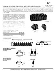
layer. See Figure <strong>4.5</strong>.1 for a diagram of a conventional trench.<br />
2) A modified onsite system would have to be installed on a site<br />
permitted as PROVISIONALLY SUITABLE. For example, in a<br />
conventional modified system, the distance between the soil surface<br />
<strong>and</strong> top of the crushed stone in the trench would only be 12 inches<br />
instead of 24 inches. See Figure <strong>4.5</strong>.1 for a diagram of one type of<br />
modified conventional trench.<br />
63
3) If a soil layer with unsuitable characteristics is located within 36<br />
inches of the surface, the soil is classified as UNSUITABLE. With<br />
further investigation <strong>and</strong> if certain site modifications are made or if<br />
certain alternative onsite systems are used; the site may be<br />
reclassified as PROVISIONALLYSUITABLE.<br />
Figure <strong>4.5</strong>.1<br />
Placement of modified conventional<br />
<strong>and</strong> conventional trenches in the soil.<br />
Reclassifying UNSUITABLE <strong>Site</strong>s.<br />
Reference<br />
15A NCAC 18A.1955(m)<br />
<strong>Site</strong>s can be reclassified from UNSUITABLE to PROVISIONALLY<br />
SUITABLE because of soil wetness or restrictive horizons if the following<br />
conditions are met:<br />
<strong>Soil</strong>s are Group I or II with SUITABLE structure <strong>and</strong> clay<br />
mineralogy;<br />
If restrictive horizons are present, <strong>and</strong> fewer than 3 inches thick<br />
or less than 12 inches from the soil surface;<br />
<strong>Site</strong> modifications can be made so that there is at least one foot<br />
of naturally occurring soil between the trench bottom <strong>and</strong><br />
saprolite, rock, or any soil horizon unsuitable because of<br />
structure, clay mineralogy, <strong>and</strong> wetness. A low-pressure pipe<br />
system must be used if the separation between the bottom of the<br />
nitrification trench <strong>and</strong> any soil wetness condition is less than<br />
18 inches <strong>and</strong> if more than 6 inches of this separation consists<br />
of Group I soils;<br />
Easements are recorded <strong>and</strong> have adequate width for access to<br />
maintain drainage systems serving two or more lots;<br />
Maintenance of the drainage system is made a condition of any<br />
permit issued for the use or operation of a sanitary sewage<br />
system;<br />
Drainage can be used in other types of soil as long as the<br />
appropriate engineering, hydrogeologic, geologic, or soil<br />
studies; <strong>and</strong><br />
A ground absorption system can be installed so that the effluent<br />
will be non-pathogenic, non-infectious, non-toxic, <strong>and</strong> nonhazardous;<br />
64
The effluent will not contaminate groundwater or surface water;<br />
<strong>and</strong><br />
The effluent will not be exposed on the ground surface or be<br />
discharged to surface waters where it could come in contact<br />
with people, animals, or vectors.<br />
Evaluating Slope <strong>and</strong><br />
L<strong>and</strong>scape Position<br />
Two factors—slope <strong>and</strong> l<strong>and</strong>scape position—determine whether water will<br />
collect at a site or flow away from the site. In general, concave or flat features<br />
accumulate water, resulting in wetter soil conditions. Convex sites tend to<br />
make water flow away from the site <strong>and</strong> are typically drier than concave or<br />
flat sites. Thus, slope <strong>and</strong> l<strong>and</strong>scape position are extremely important factors<br />
in site evaluation because these factors strongly influence how wet the site is.<br />
Slope positioning also effects the installation of septic systems. It is<br />
impossible to operate equipment for system installation on a slope greater<br />
than 65 percent.<br />
When evaluating a site for l<strong>and</strong>scape <strong>and</strong> slope positioning, the<br />
environmental health specialist must locate the best position for the onsite<br />
system. To choose the best location, the environmental health specialist must<br />
evaluate the property for overall l<strong>and</strong>scape position <strong>and</strong> for specific features.<br />
Overall topography <strong>and</strong> l<strong>and</strong>scape position can be determined by walking<br />
over the property or st<strong>and</strong>ing at a location where the l<strong>and</strong> surface can be seen.<br />
Those locations that have convex shapes or that have water flowing away<br />
from the location so that the soil is drier are the best locations for onsite<br />
systems. For example, it is better to install a treatment <strong>and</strong> disposal field on a<br />
ridge top than in a depressional area. <strong>Evaluation</strong> of soil properties from<br />
borings <strong>and</strong> pits placed in the best l<strong>and</strong>scape position generally minimizes the<br />
time required to evaluate a lot, since the best soils for a system are generally<br />
located in the best l<strong>and</strong>scape position.<br />
The specific location on the lot should be evaluated for characteristics<br />
important to onsite systems. Some factors that should be investigated are:<br />
What is the slope<br />
Does water flow to or away from the location<br />
Are there any depressional areas<br />
Are the soil depth <strong>and</strong> restrictive horizons deep enough to<br />
install the trench, given the slope<br />
In evaluating the slope <strong>and</strong> l<strong>and</strong>scape position, remember that laying out<br />
the system includes locating the system components in appropriate<br />
locations. For example, although the slope may not be a limiting factor, it<br />
may interfere with placement of some trenches due to the available soil<br />
depth.<br />
Suitability for placement of conventional onsite systems, as determined<br />
by slope, is shown below:<br />
65
Reference<br />
15A NCAC 18A-1940(a-d)<br />
For low-pressure pipe onsite systems, the slope cannot be greater than 10<br />
percent unless special design procedures are approved to assure proper<br />
distribution of effluent over the treatment <strong>and</strong> disposal field. Area-fill<br />
systems cannot be installed on slopes greater than 15 percent.<br />
Slopes < 15%<br />
Slopes 15% - 30%<br />
Slopes > 30%<br />
Complex slope patterns<br />
<strong>and</strong> slopes dissected by<br />
gullies <strong>and</strong> ravines<br />
SUITABLE<br />
PROVISIONALLY SUITABLE<br />
UNSUITABLE<br />
However, slopes 31% to 65% may be<br />
reclassified PROVISIONALLY SUITABLE if a<br />
modified system can be installed.<br />
UNSUITABLE<br />
Slope Determination.<br />
Slope is determined by measuring the change in elevation over a particular<br />
distance. Rods are held at the lowest position <strong>and</strong> the highest position. A<br />
surveyor’s level is used to read the rod heights. The difference in these<br />
heights is the change in elevation. This change in elevation is then divided by<br />
the distance between the two rods. Three examples are presented below in<br />
Figure <strong>4.5</strong>.2.<br />
Figure <strong>4.5</strong>.2<br />
Slope determination<br />
66
Reference<br />
15A NCAC 18A.1940(e,g)<br />
Two l<strong>and</strong>scape positions that are UNSUITABLE for onsite systems are<br />
depressions <strong>and</strong> wetl<strong>and</strong>s.<br />
Reference<br />
15A NCAC 18A.1937(c)<br />
Depressions<br />
Wetl<strong>and</strong>s 1<br />
UNSUITABLE unless the site is specifically<br />
approved by the local health department<br />
UNSUITABLE unless approval for on-site<br />
system installation is given in writing by the U.S.<br />
Army Corps of Engineers or the North Carolina<br />
Division of Coastal Management<br />
1<br />
The applicant is responsible for notifying the local health department of any<br />
wetl<strong>and</strong>s on the potential site.<br />
Reference<br />
15A NCAC 18A.1940(f)<br />
At sites where the l<strong>and</strong>scape position <strong>and</strong> soil properties cause water to flow<br />
over or through the soil at the site of the treatment <strong>and</strong> disposal field, the<br />
local health department may direct the use of l<strong>and</strong>scaping, surface diversions,<br />
or groundwater interceptors to reduce the surface or subsurface water flow.<br />
<strong>Soil</strong> characteristics are critical in determining the suitability of a soil for<br />
treating wastewater. In North Carolina, the four soil characteristics evaluated<br />
are texture; structure; clay mineralogy; <strong>and</strong> organic soils. These<br />
characteristics are evaluated by using soil borings <strong>and</strong> soil pits.<br />
Evaluating <strong>Soil</strong><br />
Morphological<br />
Characteristics<br />
<strong>Soil</strong> Borings <strong>and</strong> <strong>Soil</strong> Pits for <strong>Soil</strong> <strong>Evaluation</strong>.<br />
Four of the evaluation factors—wetness; depth; soil morphological<br />
characteristics; <strong>and</strong> restrictive horizons—require soil borings or digging a soil<br />
pit for proper evaluation. <strong>Soil</strong> borings are less expensive than soil pits <strong>and</strong> are<br />
sufficient to determine the suitability of the four soil factors for many sites.<br />
On sites that require a more detailed evaluation, a soil pit should be dug to<br />
determine site suitability. Pits provide a much better means to view <strong>and</strong><br />
evaluate the soil than soil borings <strong>and</strong> should be used when a detailed soil<br />
description is necessary for site suitability determination.<br />
<strong>Soil</strong> borings are identical 4 inch-diameter holes in the soil used to view the<br />
soil at a site. The borings or pit should be at least 48 inches deep or a depth at<br />
which an uncorrectable soil factor is encountered.<br />
<strong>Soil</strong> pits are holes large enough for a person to enter <strong>and</strong> view the soil<br />
closely. Backhoe-dug pits are an excellent diagnostic tool for soil depth,<br />
wetness, <strong>and</strong> restrictive horizons. Because a pit allows the evaluation of a<br />
larger cross-section than does the soil auger, the soil may be found to have<br />
different characteristics than those identified through auger sampling alone.<br />
Since the use of a backhoe-dug pit allows a more thorough soil evaluation, it<br />
may be possible to reclassify a site as PROVISIONALLY SUITABLE that<br />
would have been considered UNSUITABLE from auger borings alone prior<br />
to the pit evaluation.<br />
For example, a restrictive horizon at a site may be discontinuous. A soil pit<br />
analysis would probably reveal this discontinuity whereas a soil-auger test<br />
might not. By using soil pits, the site might be reclassified to reflect the<br />
restrictive layer discontinuity.<br />
67
Another situation in which pits are useful is for soils with stony or gravelly<br />
layers found in the Piedmont or Mountains. For these soils, a soil boring may<br />
lead the evaluator to think that a stony layer is impervious bedrock. A soil pit,<br />
on the other h<strong>and</strong>, may reveal that the layer is a stony or gravelly horizon that<br />
will not impede water flow.<br />
A soil pit, in conjunction with soil borings, must always be used when<br />
evaluating saprolite.<br />
The site factor called soil morphologic characteristics has four sub-factors<br />
which must be evaluated at each site:<br />
1.) <strong>Soil</strong> Texture.<br />
2.) <strong>Soil</strong> Structure.<br />
3.) Clay Mineralogy.<br />
4.) The Presence or Absence of Organic <strong>Soil</strong>s.<br />
<strong>Soil</strong> Texture.<br />
<strong>Soil</strong> texture is defined as the relative proportions of the various soil separates<br />
in a soil. Texture is a soil morphological property that affects a site’s<br />
suitability for treating <strong>and</strong> safely disposing of wastewater. Texture influences<br />
the hydraulic conductivity, the porosity, <strong>and</strong> the structure of the soil. <strong>Soil</strong>s<br />
with poor drainage due to heavy texture, such as clay soils, may not allow<br />
wastewater to move rapidly enough through the soil to dispose of the needed<br />
volume of wastewater. <strong>Soil</strong> texture is used to assign an acceptable loading<br />
rate of sewage to the site. Accurate determination of soil texture is critical to<br />
the determination of soil absorption system size.<br />
According to the rules<br />
“<strong>Soil</strong> textural classes means soil classification based upon size<br />
distribution of mineral particles in the fine-earth fraction less than<br />
two millimeters in diameter. The fine-earth fraction includes s<strong>and</strong><br />
(2.0-0.05 mm in diameter), silt (less than 0.05 mm-0.002 mm or<br />
greater in diameter), <strong>and</strong> clay (less than 0.002 mm in diameter)<br />
particles. The specific textural classes are . . . as shown in <strong>Soil</strong><br />
Taxonomy, Appendix I, which is hereby adopted by reference in<br />
accordance with G.S. 150B-14(c) . . .”<br />
Texture in each soil horizon is most often determined by h<strong>and</strong>. Table <strong>4.5</strong>.2<br />
presents the criteria used to determine soil textural class by h<strong>and</strong> as described<br />
in <strong>Soil</strong> Taxonomy (USDA-SCS, 1975).<br />
Laboratory analysis is more accurate than h<strong>and</strong> determination of texture <strong>and</strong><br />
is sometimes required. Laboratory determination of texture must follow the<br />
American Society for Testing Materials D-422 procedures for soil textural<br />
testing, but use the USDA particle size system for classifying the textural<br />
category. Additionally, fine loamy <strong>and</strong> clayey soils (Groups III <strong>and</strong> IV)<br />
should be soaked in a dispersing agent for 12 hours prior to the hydrometer<br />
analyses.<br />
68
Table <strong>4.5</strong>.3<br />
State of North Carolina<br />
<strong>Soil</strong> Texture Groupings<br />
For Onsite Systems.<br />
Table <strong>4.5</strong>.3 State of North Carolina <strong>Soil</strong> Texture Groupings<br />
for On-<strong>Site</strong> Wastewater Systems<br />
Suitable <strong>Soil</strong>s<br />
Provisionally Suitable <strong>Soil</strong>s<br />
Group I S<strong>and</strong> Group III Silt Loam<br />
S<strong>and</strong>y <strong>Soil</strong>s Loamy S<strong>and</strong> Fine Loamy Silt<br />
<strong>Soil</strong>s<br />
S<strong>and</strong>y Clay Loam<br />
Silty Clay Loam<br />
Clay Loam<br />
Group II S<strong>and</strong>y Loam Group IV S<strong>and</strong>y Clay<br />
Coarse Loamy Loam Clayey <strong>Soil</strong>s Silty Clay<br />
<strong>Soil</strong>s<br />
Clay<br />
Once determined, soil texture is placed into one of the 12 textural classes<br />
found in the textural triangle that was discussed in section 4.4.<br />
In North Carolina, for the purpose of onsite wastewater evaluation, the 12<br />
classes are combined into four textural groupings:<br />
Group I — S<strong>and</strong>y Texture <strong>Soil</strong>s;<br />
Group II — Coarse Loamy Texture <strong>Soil</strong>s;<br />
Group III — Fine Loamy Texture <strong>Soil</strong>s; <strong>and</strong><br />
Group IV — Clayey Texture <strong>Soil</strong>s<br />
Table <strong>4.5</strong>.3 shows how all 12 soil textural classes are assembled into these<br />
four groupings:<br />
<strong>Soil</strong>s in Group I <strong>and</strong> II are SUITABLE for onsite systems; <strong>and</strong><br />
group III <strong>and</strong> IV soils are PROVISIONALLY SUITABLE for onsite<br />
systems.<br />
Reference<br />
15A NCAC 18A.1941(a)(2)(A-F)<br />
<strong>Soil</strong> Structure.<br />
<strong>Soil</strong> structure is a way to describe how individual soil particles are arranged<br />
into larger groupings of particles called aggregates. Structure affects the rate<br />
of water movement through the soil, the amount of air that can get into the<br />
soil, <strong>and</strong> the soil’s ability to treat wastewater. Table <strong>4.5</strong>.4 describes soil<br />
structure categories, as designated in the rules, <strong>and</strong> assigns suitability classes<br />
to different soil structures.<br />
Five different soil categories are recognized for site evaluation purposes:<br />
1) Crumb <strong>and</strong> granular.<br />
2) Block-like.<br />
3) Platy.<br />
4) Prismatic.<br />
5) Absence of structure: a) single grain, <strong>and</strong> b) massive.<br />
Granular, block-like <strong>and</strong> single-grained structure types are classified suitable,<br />
because they promote internal drainage <strong>and</strong> soil separation.<br />
70
Platy, prismatic <strong>and</strong> massive structure types are classified unsuitable. Platy<br />
<strong>and</strong> massive types restrict internal drainage <strong>and</strong> aeration, while prismatic<br />
structure may provide a direct flow path for untreated wastewater from the<br />
trench bottom to a water table.<br />
Reference<br />
15 NCAC 18A.1941(a)(3)(A-B)<br />
No matter what structure type is found at a site, if the peds are very large, the<br />
structure is unsuitable, because there will be few structural voids per unit<br />
total volume of soil. Internal drainage will then be insufficient to maintain<br />
soil aeration <strong>and</strong> ad treatment.<br />
The presence of block-like structure is particularly important in some<br />
Piedmont <strong>and</strong> Mountain soils, since water flow around these block/peds<br />
allows these soils to be used for onsite waste management (refer back to the<br />
section on soil structure in the Basic <strong>Soil</strong> Concepts chapter for more details).<br />
For more information on soil structure, refer to <strong>Soil</strong> Taxonomy; Appendix I<br />
(USDA-SCS, 1975) <strong>and</strong> the Field Book for Describing <strong>Soil</strong>s (USDA-NRCS,<br />
2002).<br />
Clay Mineralogy.<br />
The type of clay mineralogy <strong>and</strong> the amount of clay in a soil influence water<br />
movement. There are different types of clays. The two major types of clay<br />
are 2:1 <strong>and</strong> 1:1 clays. 2:1 clays exp<strong>and</strong> when wet, whereas 1:1 clays exp<strong>and</strong><br />
only slightly when wet. These concepts are important to the performance of<br />
soil absorption systems as discussed below.<br />
Table <strong>4.5</strong>.4<br />
Description of <strong>Soil</strong> Structure<br />
Types <strong>and</strong> Suitability<br />
Clays with a 2:1 mineralogy, such as montmorillonite, shrink when dry <strong>and</strong><br />
swell upon wetting. When a soil swells, the soil particles exp<strong>and</strong> into the<br />
structural voids, reducing the size of the openings, <strong>and</strong> reducing total<br />
porosity. The hydraulic conductivity of the soil is therefore reduced, which<br />
limits the movement of wastewater through the soil. <strong>Soil</strong>s with 2:1 clay<br />
mineralogy are generally not suitable for onsite systems because the soil<br />
swells <strong>and</strong> restricts the flow of water.<br />
Table <strong>4.5</strong>.4 Description of <strong>Soil</strong> Structure Types <strong>and</strong> Suitability<br />
<strong>Soil</strong> Structure<br />
Type<br />
Description (if needed) Suitability<br />
Crumb <strong>and</strong><br />
granular<br />
SUITABLE<br />
Block-like<br />
Platy<br />
Prismatic<br />
Absence<br />
peds ≤ 2.5 cm (1 inch) in<br />
diameter<br />
peds > 2.5 cm (1 inch) within 36<br />
inches of the naturally occurring<br />
soil surface<br />
within 36 inches of the naturally<br />
occurring soil surface<br />
within 36 inches of the naturally<br />
occurring soil surface<br />
single grained <strong>and</strong> exhibit no<br />
structural aggregates<br />
massive <strong>and</strong> exhibit no<br />
structural peds within 36 inches<br />
of the naturally occurring soil<br />
surface<br />
PROVISIONALLY SUITABLE<br />
UNSUITABLE<br />
UNSUITABLE<br />
UNSUITABLE<br />
SUITABLE<br />
UNSUITABLE<br />
71
<strong>Soil</strong>s with 1:1 clays, such as kaolinite, have less shrink/swell potential. <strong>Soil</strong>s<br />
with 1:1 clay mineralogy are suitable for onsite systems because the soils do<br />
not swell <strong>and</strong> restrict the water flow.<br />
If the clay fraction of the soil has between 10 percent <strong>and</strong> 50 percent 2:1<br />
clays, the soil has mixed mineralogy. Some soils with mixed clay mineralogy<br />
can be used for onsite systems; some cannot. <strong>Soil</strong>s with mixed mineralogy<br />
are not suitable for onsite systems if the consistence is very firm, extremely<br />
firm, very sticky, or very plastic, because those types of consistence indicate<br />
will exp<strong>and</strong> when sewage is applied to the soil. Each soil in this class must be<br />
evaluated to determine if it is suitable for onsite wastewater disposal.<br />
<strong>Soil</strong>s with predominately 1:1 clays <strong>and</strong> less than 10 percent 2:1 clays are<br />
usable for onsite systems, because they exp<strong>and</strong> very little when sewage is<br />
applied to them, so they will maintain good internal drainage <strong>and</strong> aeration.<br />
If laboratory is substituted for field determination of clay of clay mineralogy,<br />
the American Society for Testing <strong>and</strong> Materials (ASTM) procedures must be<br />
used to determine liquid limit, plastic limit, <strong>and</strong> the plasticity index of the<br />
soils. If the Liquid limit exceeds 50 <strong>and</strong> the plastic limit exceeds 30, the<br />
sample is classified as having expansive mineralogy.<br />
<strong>Soil</strong> Consistence.<br />
Clay mineralogy can be determined in the field by evaluating soil<br />
consistence. <strong>Soil</strong> consistence is a measure of how well soil forms shapes <strong>and</strong><br />
how well it sticks to other objects. Consistence can be determined when a soil<br />
is dry, moist or wet. The best test for soil consistence in North Carolina is<br />
when the soil is moist or wet. In a moist soil, consistence is determined by<br />
looseness, friability, <strong>and</strong> firmness. If the soil has very firm or extremely firm<br />
moist consistence, the soil contains expansive mineralogy, <strong>and</strong> is classified<br />
UNSUITABLE for an onsite soil absorption system.<br />
In a wet soil, two consistency factors, soil stickiness <strong>and</strong> plasticity, should be<br />
determined. Stickiness, how well the soil adheres to other objects, is<br />
determined by pressing the soil between the fingers <strong>and</strong> thumb. Plasticity,<br />
how well the soil forms shapes, is determined by rolling the soil between the<br />
thumb <strong>and</strong> forefinger to determine whether a thin rod or wire of soil can be<br />
formed. See Table 4.4.9 in the section on Basic <strong>Soil</strong> Concepts for more<br />
details on how to evaluate soil consistence. Additional information on soil<br />
consistence can be found in the publication <strong>Soil</strong> Taxonomy (USDA-SCS,<br />
1975) <strong>and</strong> the Field Book for Describing <strong>Soil</strong>s (USDA-NRCS, 2002).<br />
If the soil is very plastic <strong>and</strong> very sticky with wet consistence, it contains<br />
expansive clay mineralogy <strong>and</strong> is classified UNSUITABLE for an onsite soil<br />
absorption system.<br />
Wet consistence is more reliable than moist consistence for the determination<br />
of clay mineralogy since water may be added by the evaluator to obtain wet<br />
consistence. Moist consistence on the other h<strong>and</strong>, depends on the available<br />
moisture at the time a soil sample is collected. Wet soil consistence should<br />
always be determined when the evaluator speculates that the site has<br />
expansive clay mineralogy.<br />
72
If the soil is classified UNSUITABLE because of structure or clay<br />
mineralogy, it may be changed to PROVISIONALLY SUITABLE if an<br />
investigation determines that a modified or alternative septic system would<br />
function appropriately on this site. See 15A NCAC 18A.1956 or .1957 for the<br />
rules governing installation of modified or alternative septic systems.<br />
The suitability of a soil for onsite system installation, based on consistence<br />
measured at either wet or moist soil conditions, is shown on Table <strong>4.5</strong>.5.<br />
<strong>4.5</strong>.5<br />
<strong>Soil</strong> Consistency Criteria<br />
For Siting Septic Systems<br />
Table <strong>4.5</strong>.5 <strong>Soil</strong> Consistency Criteria for Siting Septic Systems<br />
Evaluated at Moist Evaluated at Wet Water<br />
Clay Mineralogy Suitability<br />
Water Content Content<br />
Slightly expansive<br />
(includes nonexpansive)<br />
SUITABLE<br />
Loose, very friable,<br />
friable, or firm<br />
*<br />
Non-sticky, slightly sticky to<br />
sticky or non-plastic, slightly<br />
plastic to plastic<br />
Expansive UNSUITABLE Very firm or extremely<br />
firm<br />
Very sticky, very plastic<br />
Reference<br />
15A NCAC 18A.1941(a)(4)<br />
Organic matter.<br />
Organic soils, soils with 20 percent or more organic matter by weight to a<br />
depth of 18 inches or greater, are always UNSUITABLE as locations for<br />
onsite systems. These soils remain wet throughout most of the year because<br />
they drain too slowly. Organic soils may also burn or subside causing the<br />
onsite system to be destroyed.<br />
<strong>Soil</strong> Wetness.<br />
Adequate treatment of wastewater can only occur in well-aerated soils.<br />
When the soil is wet, soil voids are filled with water <strong>and</strong> there is insufficient<br />
soil aeration to properly treat wastewater. Since wet soils do not allow<br />
adequate treatment of wastewater, onsite systems cannot be installed in wet<br />
soils.<br />
<strong>Soil</strong> color is used to indicate soil wetness. Once the soil colors <strong>and</strong> the depth<br />
of these colors have been determined, the soil can be classified for suitability<br />
on onsite system installation based on wetness.<br />
Chroma is the relative strength, purity, or saturation of the color of the soil.<br />
Chromas of two on the Munsell color chart, either in mottles or as a solid soil<br />
mass, often indicate wet soil. The wetness could be caused by a seasonal<br />
high-water table, perched water table, tidal water, soils that are saturated<br />
during the rainy season or movement of groundwater into <strong>and</strong> through the<br />
soil. The relationships between the depth to the soil with chroma two less<br />
color <strong>and</strong> the site suitability for installation of an onsite system are presented<br />
in Table <strong>4.5</strong>.6.<br />
73
Table <strong>4.5</strong>.6<br />
<strong>Soil</strong> Wetness <strong>and</strong><br />
<strong>Site</strong> Suitability<br />
Table <strong>4.5</strong>.6 <strong>Soil</strong> Wetness <strong>and</strong> <strong>Site</strong> Suitability<br />
<strong>Soil</strong> Wetness Depth (from<br />
<strong>Soil</strong> Surface)<br />
Suitability<br />
> 48" SUITABLE<br />
36 - 48"<br />
PROVISIONALLY<br />
SUITABLE<br />
< 36" UNSUITABLE<br />
Sometimes soil color is an artifact of the original parent material <strong>and</strong> is not<br />
indicative of soil wetness. <strong>Soil</strong> colors of chroma 2 or less, which are relic<br />
from minerals of the parent material shall not be considered indicative of a<br />
soil wetness condition.<br />
Other site characteristics can be used to indicate soil wetness. Vegetation <strong>and</strong><br />
l<strong>and</strong>scape position can be used as an initial indicator of wet areas. The<br />
presence of waterborne vegetation <strong>and</strong> a depressional l<strong>and</strong>scape position<br />
would suggest that identified gray colors are most likely due to soil wetness<br />
<strong>and</strong> not relic parent materials.<br />
<strong>Soil</strong> Wetness<br />
If the site has been drained, the soil must be evaluated for soil wetness by<br />
monitoring the site with monitoring wells from December through March to<br />
determine the water table depth.<br />
In the Piedmont, interceptor drains may be used for controlling perched water<br />
tables. In the mountains, these drains can divert laterally moving water in<br />
colluvial soils. In the Coastal Plain, ground-water-lowering devices, such as<br />
subsurface tiles, ditches, or pumped drainage, are frequently used, when the<br />
soil texture is Group 1 or Group 2 <strong>and</strong> other soil properties are suitable.<br />
If the soil is UNSUITABLE because of wetness, the classification may be<br />
changed to PROVISIONALLY SUITABLE if an investigation determines<br />
that a modified or alternative septic system would function appropriately on<br />
this site. See 15A NCAC 18A.1956 or .1957 for the rules governing<br />
installation of modified or alternative septic systems. Direct monitoring of<br />
the water table as prescribed in 15A NCAC 18.1942 may also be utilized to<br />
demonstrate that soil wetness as determined by soil color is not accurate for<br />
this site.<br />
<strong>Soil</strong> Depth<br />
<strong>Soil</strong>s must have enough depth so that wastewater is properly treated.<br />
Research performed by Bauma <strong>and</strong> Reneau has demonstrated for most soils<br />
that there must be at least 12 inches of suitable soil under an absorption<br />
trench to properly treat septic tank effluent. Cogger has demonstrated that<br />
this depth must be increased for s<strong>and</strong>y soils. <strong>Soil</strong> depth from the soil surface<br />
to the saprolite, rock, or parent material is a major factor in determining the<br />
suitability of the site for onsite systems. See Figure <strong>4.5</strong>.3 for a drawing<br />
showing soil depth requirements, as stated in the rules.<br />
74
Figure <strong>4.5</strong>.3<br />
<strong>Soil</strong> depth<br />
<strong>and</strong> site suitability<br />
Aerated soil with more than 12 inches beneath the trenches is generally<br />
required to treat wastewater adequately. However, a total of 48 inches of<br />
acceptable soil is necessary for conventional onsite system installation. If the<br />
total soil depth is between 36 inches <strong>and</strong> 48 inches, a modified onsite system<br />
can be installed, requiring 12-24 inches of soil above the trench, a 12 inch<br />
trench, <strong>and</strong> 12 inches below the trench.<br />
Reference<br />
15A NCAC 18A.1943(b)<br />
Reference<br />
15A NCAC 18A.1957(a)(2)(B)<br />
The only soil depth requirement exception is for sites with less than 36 inches<br />
<strong>and</strong> the site evaluation has determined that a modified or alternative system<br />
can be installed. For instance, site suitability for low-pressure pipe systems<br />
must be based on the first 24 inches of soil beneath the naturally occurring<br />
soil <strong>and</strong> surface. See 15A NCAC 18A.1956 or .1957 for the rules governing<br />
installation of modified or alternative septic systems.<br />
<strong>Soil</strong> depth <strong>and</strong> slope.<br />
On steep slopes, the depth of soil required for installation of trenches may be<br />
greater than on sites with little or no slope. This extra soil depth is needed to<br />
keep the bottom of the trench level <strong>and</strong> at the proper depth on the sloping<br />
site. For example, if a treatment <strong>and</strong> disposal field has a slope of 60 percent<br />
<strong>and</strong> a modified conventional system with a trench depth of 24 inches is to be<br />
installed, then the minimum soil depth at the lowest elevation must be 57.6<br />
inches. This depth is required because on a 60 percent slope with a 36 inch<br />
wide trench, there is a difference of 21.6 inches between the uphill <strong>and</strong><br />
downhill sides of the trench. To keep the downhill side of the trench 24<br />
inches deep <strong>and</strong> to have 12 inches of soil under the trench bottom, there must<br />
be 57.6 inches (21.6 + 24 +12) of total soil depth.<br />
See Figure <strong>4.5</strong>.4 for another explanation of the extra depth of soil required to<br />
install trenches on slopes. Table <strong>4.5</strong>.7 lists the differences in the uphill <strong>and</strong><br />
downhill sides of a trench for trenches of various widths on various slopes.<br />
75
Figure <strong>4.5</strong>.4<br />
Difference in depth<br />
in inches between uphill<br />
<strong>and</strong> downhill side of trench.<br />
Reference<br />
15A NCAC 18A.1956(6)<br />
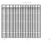
Example: For a trench width (W) of 36 inches <strong>and</strong> a slope of 40 percent, the<br />
difference between the uphill <strong>and</strong> downhill side of the trench (D-d) is 14.4<br />
inches. For a trench depth (d) of 18 inches <strong>and</strong> a minimum separation from<br />
trench bottom of 12 inches, the required minimum soil depth is 18+12+14.4 =<br />
44.4 inches.<br />
<strong>Soil</strong> Depth <strong>and</strong> The Use of Saprolite.<br />
If soils are not deep enough to install an onsite system but are underlain by<br />
saprolite, the site may be reclassified as PROVISIONALLY SUITABLE<br />
under certain conditions. A trench or pit investigation of the saprolite must be<br />
conducted in order to determine if the following physical properties <strong>and</strong><br />
characteristics are met:<br />
Saprolite must have weathered from igneous or metamorphic<br />
rocks;<br />
Saprolite texture must be s<strong>and</strong>, loamy s<strong>and</strong>, s<strong>and</strong>y loam, loam,<br />
or silt loam;<br />
Clay mineralogy must be SUITABLE (non or slightly<br />
expansive);<br />
Moist saprolite consistence must be loose, friable to very friable<br />
or firm for more than 2/3 of the material;<br />
Wet saprolite consistence must be nonsticky or slightly sticky<br />
<strong>and</strong> nonplastic or slightly plastic; <strong>and</strong><br />
The saprolite must have no open <strong>and</strong> continuous joints, quartz<br />
veins, or fractures relic of parent material to a depth of 2 feet<br />
below the proposed trench bottom.<br />
Saprolite depth. When saprolite is used rather than soil to treat wastewater, a<br />
separation distance of 24 inches is necessary between the bottom of the<br />
trench <strong>and</strong> any weathered rock or bedrock (Figure <strong>4.5</strong>.5). If the trench is<br />
places partially in soil <strong>and</strong> partially in saprolite, then the separation distance<br />
is 24 inches – x, where x is the depth of the soil in inches (Figure <strong>4.5</strong>.5). For<br />
example, if a 12 inch trench was composed of 9 inches of soil <strong>and</strong> 3 inches of<br />
saprolite, then the total depth of saprolite necessary to treat the wastewater<br />
would be 15 inches (24 inches – 9 inches = 15 inches).<br />
76
77<br />
Figure <strong>4.5</strong>.5<br />
Trench placement<br />
in saprolite soil <strong>and</strong> a mixed<br />
soil/saprolite.
Table <strong>4.5</strong>.7<br />
<strong>Soil</strong> Wetness Depth<br />
<strong>and</strong> <strong>Site</strong> Suitability<br />
Table <strong>4.5</strong>.7 <strong>Soil</strong> Wetness <strong>and</strong> <strong>Site</strong> Suitability<br />
Slope<br />
Trench Width (Inches)<br />
(%) 12 15 18 21 24 27 30 36<br />
2.0 0.2 0.3 0.4 0.4 0.5 0.5 0.6 0.7<br />
4.0 0.5 0.6 0.7 0.8 1.0 1.1 1.2 1.4<br />
6.0 0.7 0.9 1.1 1.3 1.4 1.6 1.8 2.2<br />
8.0 1.0 1.2 1.4 1.7 1.9 2.2 2.4 2.9<br />
10.0 1.5 1.5 1.8 2.1 2.4 2.7 3.0 3.6<br />
12.0 1.4 1.8 2.2 2.5 2.9 3.2 3.6 4.3<br />
14.0 1.7 2.1 2.5 2.9 3.4 3.8 4.2 5.0<br />
16.0 1.9 2.4 2.9 3.4 3.8 4.3 4.8 5.8<br />
18.0 2.2 2.7 3.2 3.8 4.3 4.9 5.4 6.5<br />
20.0 2.4 3.0 3.6 4.2 4.8 5.4 6.0 7.2<br />
22.0 2.6 3.3 4.0 4.6 5.3 5.9 6.6 7.9<br />
24.0 2.9 3.6 4.3 5.0 5.8 6.5 7.2 8.6<br />
26.0 3.1 3.9 4.7 5.5 6.2 7.0 7.8 9.4<br />
28.0 3.4 4.2 5.0 5.9 6.7 7.6 8.4 10.1<br />
30.0 3.6 <strong>4.5</strong> 5.4 6.3 7.2 8.1 9.0 10.8<br />
32.0 3.8 4.8 5.8 6.7 7.7 8.6 9.6 11.5<br />
34.0 4.1 5.1 6.1 7.1 8.2 9.2 10.2 12.2<br />
36.0 4.3 5.4 6.5 7.6 8.6 9.7 10.8 13.0<br />
38.0 4.6 5.7 6.8 8.0 9.1 10.3 11.4 13.7<br />
40.0 4.8 6.0 7.2 8.4 9.6 10.8 12.0 14.4<br />
42.0 5.0 6.3 7.6 8.8 10.1 11.3 12.6 15.1<br />
44.0 5.3 6.6 7.9 9.2 10.6 11.9 13.2 15.8<br />
46.0 5.5 6.9 8.3 9.7 11.0 12.4 13.8 16.6<br />
48.0 5.8 7.2 8.6 10.1 11.5 13.0 14.4 17.3<br />
50.0 6.0 7.5 9.0 10.5 12.0 13.5 15.0 18.0<br />
52.0 6.2 7.8 9.4 10.9 12.5 14.0 15.6 18.7<br />
54.0 6.5 8.1 9.7 11.3 13.0 14.6 16.2 19.4<br />
56.0 6.7 8.4 10.1 11.8 13.4 15.1 16.8 20.2<br />
58.0 7.0 8.7 10.4 12.2 13.9 15.7 17.4 20.9<br />
60.0 7.2 9.0 10.8 12.6 14.4 16.2 18.0 21.6<br />
78
Restrictive Horizons<br />
Reference<br />
15 NCAC 18A.1944(a)<br />
The depth where restrictive horizons are located is important when<br />
determining the suitability of a site. Since restrictive horizons retard<br />
wastewater flow, the presence of these horizons, if they are too close to the<br />
soil surface, can disqualify a site for onsite system installation.<br />
As defined in the rules, restrictive horizon means<br />
“a soil horizon that is capable of perching groundwater or sewage<br />
effluent <strong>and</strong> that is brittle <strong>and</strong> strongly compacted or strongly<br />
cemented with iron, aluminum, silica, organic matter, or other<br />
compounds. Restrictive horizons may occur as fragipans, iron pans,<br />
or organic pans, <strong>and</strong> are recognized by their resistance in excavation<br />
or in using a soil auger.”<br />
Reference<br />
15A NCAC 18A.1944(b)<br />
For purposes of site evaluation, restrictive horizons are defined as layers of<br />
material that are at least 3 inches thick <strong>and</strong> are continuous in a horizontal<br />
direction. See Figure <strong>4.5</strong>.6, which shows the relationship between restrictive<br />
horizon depth <strong>and</strong> suitability for onsite system installation.<br />
The only exception to the restrictive horizon depth requirement is for sites<br />
where the restrictive horizon is less than 36 inches from the surface <strong>and</strong><br />
where the site evaluation has determined that a modified or alternative system<br />
can be installed. See 15A NCAC 18A.1956 or .1957 for the rules governing<br />
installation of modified or alternative septic systems.<br />
Restrictive horizons will cause a soil wetness condition to occur above them.<br />
If the restrictive horizon is less than 3 inches thick <strong>and</strong> is discontinuous<br />
horizontally, the wetness condition may be reclassified PROVISIONALLY<br />
SUITABLE when artificial drainage is installed.<br />
Figure <strong>4.5</strong>.6<br />
<strong>Soil</strong> restrictive layers<br />
<strong>and</strong> site suitability.<br />
79
Available Space<br />
Reference<br />
15A NCAC 18A.1945(a)<br />
Reference<br />
15A NCAC 18A. 1945(b)<br />
Available space for onsite systems depends on both the area of acceptable<br />
soil <strong>and</strong> site conditions <strong>and</strong> the required separation distances between the<br />
onsite system <strong>and</strong> buildings, water supplies, <strong>and</strong> other structures.<br />
Onsite Space Needed.<br />
<strong>Site</strong>s for onsite systems must be large enough to allow installation <strong>and</strong> proper<br />
functioning of the systems. There must be enough area for the treatment <strong>and</strong><br />
disposal field so that the system has long-term reliability. (See <strong>Section</strong> 4.6 for<br />
information on long-term acceptance rates of septic wastewater.)<br />
In addition to the area needed for the treatment <strong>and</strong> disposal field, sites must<br />
be large enough area for a repair or replacement system that is set aside. The<br />
repair area would be used to install another treatment <strong>and</strong> disposal field if the<br />
original treatment <strong>and</strong> disposal field fails.<br />
In the rules, the definition of the repair area is<br />
“an area, either in its natural state or which is capable of being<br />
modified, consistent with these rules, which is reserved for the<br />
installation of additional nitrification fields <strong>and</strong> is not covered with<br />
structures or impervious materials.”<br />
Reference<br />
15A NCAC 18A.1945(c)<br />
The size of repair areas must conform to the rules for the design criteria of<br />
conventional sewage systems (15A NCAC 18A.1955), modifications to septic<br />
tank systems (15A NCAC 18A.1956), alternative sewage systems (15A NCAC<br />
18A.1957). Innovative Sewage Systems (15A NCAC 18A.1969) or<br />
Pretreatment Systems (15A NCAC 18A.1970). For example, the initial<br />
system may be a conventional septic system with four trenches, 9 feet on<br />
center <strong>and</strong> 80 feet long; <strong>and</strong> the replacement may be a low pressure pipe<br />
distribution system with 10 trenches, 5 feet on center, <strong>and</strong> 80 feet long. The<br />
repair area must also conform to the necessary setbacks. The Improvement<br />
Permit must designate the original system layout, repair area, <strong>and</strong> type of<br />
replacement system.<br />
There are exceptions to the repair area criteria described above. If a site or<br />
tract of l<strong>and</strong> meets all of the following criteria then it is exempt from the<br />
repair area space requirement when all the following exist:<br />
The lot or tract of l<strong>and</strong> was on record with the Register of Deeds<br />
at the court house on January 1, 1983;<br />
The lot is of insufficient size to satisfy the repair area<br />
requirements; <strong>and</strong><br />
A system of no more than 480 gallons design daily flow is to be<br />
installed.<br />
Lots exempt from the replacement system area requirement must reserve the<br />
maximum feasible area for repairs or expansion of the initial system.<br />
Horizontal distance placement requirements.<br />
A site must have enough space to install the onsite system <strong>and</strong> to keep a<br />
separation between the system <strong>and</strong> certain features or structures. Onsite<br />
systems must be set back certain distances from water supply sources,<br />
streams, lakes, drains, buildings, property lines, <strong>and</strong> other features. These<br />
minimum setback distances are to protect water wells, streams, <strong>and</strong> homes<br />
from pollution by the onsite system. They allow sufficient areas to install the<br />
system <strong>and</strong> space for the treatment <strong>and</strong> disposal of wastewater.<br />
80
Placement distances for conventional <strong>and</strong> modified onsite systems are<br />
presented in Figures <strong>4.5</strong>.7- <strong>4.5</strong>.9 on the following pages:<br />
Figure <strong>4.5</strong>.7<br />
Onsite treatment <strong>and</strong> disposal<br />
system component placement<br />
Distances for flows fewer<br />
Than 3,000 gallons/day.<br />
81
Figure <strong>4.5</strong>.8<br />
Onsite disposal system<br />
placement distances for flows<br />
greater than 3,000 per day with<br />
one or more treatment <strong>and</strong><br />
disposal fields receiving more<br />
than 1,500 gallons per day.<br />
Figure <strong>4.5</strong>.9<br />
Onsite system placement<br />
distances for collections<br />
sewers, force mains, <strong>and</strong><br />
supply lines.<br />
82
Table <strong>4.5</strong>.8<br />
Location of Sewer Lines<br />
Rules for the placement of sewer lines crossing a water line, a storm drain,<br />
<strong>and</strong> a stream are presented in Table <strong>4.5</strong>.8.<br />
Reference<br />
15A NCAC 18A.1950(f,g,h)<br />
Table <strong>4.5</strong>.8 Location of Sewer Lines<br />
Water lines<br />
Separation Distance/Sewer Line<br />
Location<br />
Sewer lines may cross a water line if<br />
18 inches of clear separation<br />
distance is maintained, with the<br />
sewer line passing under the water<br />
line.<br />
Required Construction<br />
If conditions prevent 18-inch separation from being<br />
maintained or whenever it is necessary for the water line<br />
to cross under the sewer, the sewer line shall be<br />
constructed of ductile iron pipe or its equivalent <strong>and</strong> the<br />
water line shall be constructed of ferrous materials<br />
equivalent to water main st<strong>and</strong>ards for a distance of at<br />
least 10 feet on each side at the point of crossing, with<br />
full sections of pipe centered at the point of crossing.<br />
Storm drains<br />
Streams<br />
Sewer lines may cross a storm drain<br />
if 12 inches of clear separation<br />
distance is maintained.<br />
Sewer lines may cross a stream if at<br />
least three feet of stable cover can<br />
be maintained.<br />
Sewer lines may also cross a storm drain if the sewer is<br />
of ductile iron pipe or encased in concrete or ductile iron<br />
pipe for at least five feet on either side of the crossing.<br />
Sewer lines may also cross a stream if the sewer line is<br />
of ductile iron pipe or encased in concrete or ductile iron<br />
pipe for at least 10 feet on either side of the crossing <strong>and</strong><br />
protected against the normal range of high <strong>and</strong> low<br />
water conditions, including the 100-year flood/wave<br />
action. Aerial crossings shall be by ductile iron pipe with<br />
mechanical joints or steel pipe. Pipes shall be anchored<br />
for at least 10 feet on either side of the crossing.<br />
Source: Laws <strong>and</strong> Rules for Sewage Treatment <strong>and</strong> Disposal Systems . 1992. North Carolina Department of Environment, <strong>Health</strong>, <strong>and</strong> Natural Resources,<br />
Division of <strong>Environmental</strong> <strong>Health</strong> On-<strong>Site</strong> Wastewater <strong>Section</strong>.<br />
83
Some exceptions to the rules <strong>and</strong> general provisions for separation distances<br />
are listed in Table <strong>4.5</strong>.9.<br />
Table <strong>4.5</strong>.9<br />
Additional Rules for<br />
Locating Onsite Systems<br />
Reference<br />
15A NCAC 18A. 1950 (b)<br />
Table <strong>4.5</strong>.9 Additional Rules for Locating On-<strong>Site</strong> Systems<br />
Wastewater System<br />
Component<br />
Location <strong>and</strong> Construction Requirement<br />
Ground absorption sewage May be located closer than 100 feet from private<br />
treatment <strong>and</strong> disposal water supply but no closer than 50 feet. Springs or<br />
uncased wells that are down slope <strong>and</strong> used as a<br />
system <strong>and</strong> repair areas.<br />
drinking water source require 100 foot separation.<br />
Reference<br />
15A NCAC 18A. 1950(c)<br />
Reference<br />
15A NCAc 18A. 1955(e)<br />
Reference<br />
15A NCAC 18A.1950(i)<br />
Treatment <strong>and</strong> disposal<br />
fields <strong>and</strong> repair areas.<br />
Septic tanks, lift stations,<br />
wastewater treatment<br />
plants, s<strong>and</strong> filters, <strong>and</strong><br />
other pre-treatment<br />
systems.<br />
These fields cannot be located under paved areas or<br />
areas that have vehicle traffic. If pipe runs under<br />
vehicle traffic areas, then the conveyance pipe must<br />
be made of ductile iron or an equivalent pipe, or a<br />
Schedule 40 PVC, PE or ABS pipe must be instal<br />
These structures cannot be located in areas of<br />
frequent flooding (more often than the 10-year event)<br />
unless they are watertight <strong>and</strong> can operate during a<br />
10-year storm. All mechanical <strong>and</strong> electrical<br />
equipment must be placed above the 100-year flood<br />
level o<br />
If the sewage is pretreated, placement distances can be reduced. These<br />
distances are presented in Figure <strong>4.5</strong>.10 for aerobic treatment units <strong>and</strong><br />
Figure <strong>4.5</strong>.11 for TS-1 <strong>and</strong> TS-II systems.<br />
Figure <strong>4.5</strong>.10<br />
Onsite system<br />
placement distances<br />
from individual aerobic<br />
sewage treatment units.<br />
84
Additional <strong>Evaluation</strong><br />
Factors<br />
Reference<br />
15A NCAC 18A.1946(4)<br />
There are a number of situations where other factors, in addition to the above<br />
six site factors, must be considered.<br />
High-Capacity Wells.<br />
All pumping wells create a cone of influence, an area around the well where<br />
the groundwater level is lowered by the withdrawal through the well. Highcapacity<br />
wells, such as community, municipal, <strong>and</strong> industrial water supply<br />
wells, pump more water <strong>and</strong> have much larger cones of influence than<br />
household wells. These large cones of influence must be considered when<br />
locating onsite systems. Thus, onsite systems may need to be located much<br />
farther away from large wells than the required 100 feet, as shown in Figure<br />
<strong>4.5</strong>.7.<br />
Large Onsite Systems.<br />
For onsite systems discharging more than 3,000 gallons per day, certain<br />
information must be collected to predict the height of the water table mound<br />
below the treatment <strong>and</strong> disposal field <strong>and</strong> the flow rate of the wastewater<br />
from the treatment <strong>and</strong> disposal field trenches. <strong>Soil</strong> borings to depths greater<br />
than 48 inches, permeability <strong>and</strong> hydraulic conductivity measurements, <strong>and</strong><br />
water level readings must typically be collected. If these measurements<br />
indicate that the water table will not remain two or more feet below the<br />
treatment <strong>and</strong> disposal field or that the wastewater will rise to the surface, the<br />
site must be classified as UNSUITABLE. More detail on conducting site<br />
evaluations for large systems can be found in <strong>Section</strong> 4.6.<br />
Hydraulic conductivity measurement techniques <strong>and</strong> other tests in<br />
relationship to some soil morphological characteristics. Hydraulic<br />
conductivity is the measure of the rate water moves through the soil. The rate<br />
of water movement through a soil is influenced by texture, structure, <strong>and</strong><br />
mineralogy, because these soil morphological characteristics determine the<br />
size <strong>and</strong> the connectivity of the pores, which in turn determines the speed of<br />
water movement. Hydraulic conductivity measurements may be required, in<br />
addition to the normal size evaluation, to determine site suitability. With<br />
large systems, where the flow to a single nitrification field is more than 1,500<br />
gallons per day. For the design of artificial drainage systems used to modify<br />
sites for onsite systems. When pretreatment systems are proposed to reduce<br />
required system area or depth.<br />
In most situations, the usual site evaluation is enough to determine the<br />
suitability of the site or lot for onsite systems. For sites located on benchmark<br />
soils (soils that are typical to North Carolina), additional information on<br />
hydraulic conductivity is available.<br />
Hydraulic conductivity tests. Determining hydraulic conductivity requires a<br />
proper test method. Many hydraulic conductivity tests have been devised <strong>and</strong><br />
are in use in different areas. A good source for information on hydraulic<br />
conductivity tests is the article by Amoozegar <strong>and</strong> Warrick, 1985, in<br />
Appendix B.<br />
85
The two methods most commonly used in North Carolina when the soil<br />
hydraulic conductivity measurements are necessary are the constant-head<br />
permeameter test <strong>and</strong> the auger-hole pump out test.<br />
Constant-head permeameter test. The constant-head permeameter, also called<br />
the shallow well pump-in method, is a common technique used to measure<br />
saturated hydraulic conductivity. This test works best where the water table is<br />
relatively deep. A source of water is required to saturate the soil for this test.<br />
See the publication by Amoozegar <strong>and</strong> Warrick, 1985, or Appendix 2, for<br />
more information on constant head permeameter tests.<br />
To run the test, a hole is bored to a desired depth <strong>and</strong> enough water is poured<br />
into the hole to maintain a certain depth of water in the hole, usually 6 inches<br />
(for a 2.5 inch diameter hole). After a while, the flow rate of the water out of<br />
the hole through the soil will be constant. This flow rate should be measured,<br />
along with the diameter of the hole, the depth of the water in the auger hole,<br />
<strong>and</strong> the distance between the bottom of the hole <strong>and</strong> any restrictive layers.<br />
Equations provided in Appendix B are used to calculate saturated hydraulic<br />
conductivity from the measurements.<br />
Auger-hole pump-out test. The auger-hole pump-out method, or auger-hole<br />
method, is the most commonly used test to measure saturated hydraulic<br />
conductivity where the water table is near the surface. More details on this<br />
test can be found in the article by Amoozegar <strong>and</strong> Warrick, 1985, in<br />
Appendix B.<br />
In this test, a hole is dug below the water table, using a soil auger to minimize<br />
soil disturbance. The hole needs to fill with water <strong>and</strong> be pumped out several<br />
times before the actual test. When the test begins, the groundwater is allowed<br />
to rise in the hole to the level of the water table. Then, the water is pumped<br />
out of the hole <strong>and</strong> the rate at which the water rises in the hole is measured.<br />
To calculate the saturated hydraulic conductivity, the depth of the water in<br />
the hole, the diameter of the hole, <strong>and</strong> the distance between the restrictive<br />
layer below the hole <strong>and</strong> the bottom of the hole must be determined. Several<br />
different calculation techniques can be used. See Appendix B for more<br />
information on this test.<br />
As mentioned above, there are a number of methods for determining<br />
hydraulic conductivity. In Methods of <strong>Soil</strong> Analysis, Amoozegar <strong>and</strong> Warrick<br />
have separated shallow water table methods from deep water table methods.<br />
The methods described by Amoozegar <strong>and</strong> Warrick are listed below. More<br />
information can be found in Appendix B.<br />
Shallow water table methods include the auger-hole pump-out method, the<br />
piezometer method, <strong>and</strong> other techniques. Deep water table methods are the<br />
double-tube, the shallow well pump-in, the cylindrical permeameter, the<br />
infiltration-gradient, <strong>and</strong> the air-entry permeameter methods. Since North<br />
Carolina uses site evaluation to determine site suitability, it is essential to<br />
evaluate all six factors—slope <strong>and</strong> l<strong>and</strong>scape position; soil morphological<br />
characteristics; soil wetness, soil depth; restrictive horizons; <strong>and</strong> available<br />
space—<strong>and</strong> to compile them into a suitability rating. An aquifer test which<br />
utilizes a pumping well <strong>and</strong> recovery well may be needed for hydraulic<br />
conductivity measurement when large systems are sited.<br />
86
Compilation of <strong>Site</strong><br />
Information<br />
Reference<br />
15A NCAC 18A.1947<br />
References<br />
If the ratings are the same for all six evaluation factors, then that rating is the<br />
site’s classification. For example, on a site where each individual factor is<br />
designated as SUITABLE, the site would receive a SUITABLE<br />
classification.<br />
If some of the site evaluation factors are different, then the most limiting<br />
factor that cannot be corrected determines the overall site suitability<br />
classification. If, for example, one of the six factors is deemed<br />
UNSUITABLE <strong>and</strong> cannot be corrected, then the site will be classified as<br />
UNSUITABLE. Several examples of uncorrectable limiting factors are listed<br />
below:<br />
The setbacks from existing wells on the property or on adjacent<br />
property are not far enough away (as specified in the rules) from<br />
the proposed onsite system;<br />
A dissected toe slope or depression is part of the site’s<br />
l<strong>and</strong>scape position;<br />
The slope is greater than 65 percent <strong>and</strong><br />
The clay mineralogy is 2:1.<br />
Amoozegar, A. <strong>and</strong> A.W. Warrick. 1986. Hydraulic Conductivity of<br />
Saturated <strong>Soil</strong>s: Field Methods. In Methods of <strong>Soil</strong> Analysis, Part I.<br />
Physical <strong>and</strong> Mineralogical Methods, (eds). Agronomy Monograph<br />
No. 9, 2nd edition. American Society of Agronomy – <strong>Soil</strong> Science<br />
Society of America, Madison, WI.<br />
Hoover, M.T. Unpublished mimeo. Principles of <strong>Site</strong> <strong>Evaluation</strong>. <strong>Soil</strong><br />
Science Department, North Carolina State University, Raleigh, NC.<br />
Kleiss, H.J. <strong>and</strong> M.T. Hoover. 1986. <strong>Soil</strong> <strong>and</strong> <strong>Site</strong> Criteria for Onsite<br />
Systems. In Utilization, Treatment, <strong>and</strong> Disposal of Waste on L<strong>and</strong>.<br />
<strong>Soil</strong> Science Society of America, Madison, WI.<br />
USDA-SCS. 1975. <strong>Soil</strong> Taxonomy: A Basic System of <strong>Soil</strong><br />
Classification for Making <strong>and</strong> Interpreting <strong>Soil</strong> Surveys. U.S.<br />
Department of Agriculture, <strong>Soil</strong> Conservation Service, <strong>Soil</strong> Survey<br />
Staff, Agriculture H<strong>and</strong>book No. 436. Washington, DC<br />
87