NC Low Profile Chamber Installation Guidelines - Environmental ...
NC Low Profile Chamber Installation Guidelines - Environmental ...
NC Low Profile Chamber Installation Guidelines - Environmental ...

Create successful ePaper yourself
Turn your PDF publications into a flip-book with our unique Google optimized e-Paper software.
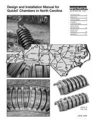
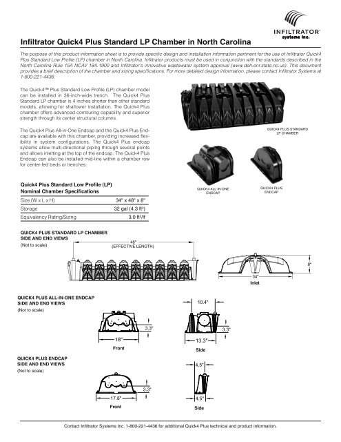
infiltrator quick4 plus Standard lp chamber in north carolinaThe purpose of this product information sheet is to provide specific design and installation information pertinent for the use of Infiltrator Quick4Plus Standard <strong>Low</strong> <strong>Profile</strong> (LP) chamber in North Carolina. Infiltrator products must be used in conjunction with the standards described in theNorth Carolina Rule 15A <strong>NC</strong>AV 18A.1900 and Infiltrator’s innovative wastewater system approval (www.deh.enr.state.nc.us). This documentprovides a brief description of the chamber and sizing specifications. For more detailed design information, please contact Infiltrator Systems at1-800-221-4436.The Quick4 Plus Standard <strong>Low</strong> <strong>Profile</strong> (LP) chamber modelcan be installed in 36-inch-wide trench. The Quick4 PlusStandard LP chamber is 4 inches shorter than other standardmodels, allowing for shallower installation. The Quick4 Pluschamber offers advanced contouring capability and superiorstrength through its center structural columns.The Quick4 Plus All-in-One Endcap and the Quick4 Plus Endcapare available with this chamber, providing increased flexibilityin system configurations. The Quick4 Plus endcapsystems allow multi-directional piping through several pointsand allows inletting at the top of the endcap. The Quick4 PlusEndcap can also be installed mid-line within a chamber rowfor center-fed beds or trenches.QUICK4 PLUS STANDARDLP CHAMBERquick4 plus Standard low profile (lp)nominal chamber SpecificationsSize (W x L x H) 34" x 48" x 8"Storage 32 gal (4.3 ft 3 )Equivalency Rating/Sizing3.0 ft 2 /lfQUICK4 ALL-IN-ONEENDCAPQUICK4 PLUSENDCAPquick4 pluS Standard lp chamberSide and end viewS(Not to scale)48"(EFFECTIVE LENGTH)8"34"inletquick4 pluS all-in-one endcapSide and end viewS(Not to scale)10.4"3.3"3.3"18"13.3"Front Sidequick4 pluS endcapSide and end viewS(Not to scale)4.5"3.3"17.8"Front4.5"SideContact Infiltrator Systems Inc. 1-800-221-4436 for additional Quick4 Plus technical and product information.
quick4 pluS all-in-one periScopeSide view(Not to scale)QUICK4 PLUS PERISCOPEINVERT 9"QUICK4 PLUSALL-IN-ONEENDCAPquick4 pluS all-in-one endcap invertS(Not to scale)1" PRESSURELATERAL (TYP.)2" PRESSURELATERAL (TYP.)TOP 9" INVERT (INLET OR OUTLET)END OR SIDE 3.3" INVERT(GRAVITY INLET OR OUTLET)END OR SIDE 0.5” INVERT(FOR MID-LINE CONNECTIONOR LOOPED ENDS)table 1: 3 Ft 2 /lF equivalency rating Factor – quick4 pluS Standard lp chamberStone & Pipe Conventional TrenchQ4 Plus Standard LP <strong>Chamber</strong>Natural SoilTexturalLTAR2 Bedroom 3 Bedroom 4 BedroomGroup(gpd.sq ft)Soil Group ISandsSoil Group IICoarse LoamsSoil Group IIIFine LoamsSoil Group IVClays2 BedroomTrenchLength (ft)3 BedroomTrenchLength (ft)4 BedroomTrenchLength (ft)TrenchLength (ft)<strong>Chamber</strong>sRequiredTrenchLength (ft)<strong>Chamber</strong>sRequiredNotes: 1) Required trench bottom (sq ft) = design daily sewage flow (120 gallons per bedroom) / applicable long term acceptance rate2) <strong>Chamber</strong> sizing shall be calculated using the following ratings Quick4 Plus Standard LP at 3 sq ft/lf3) To calculate sizing for additional bedrooms multiply the number of bedrooms by 120 and divide by the applicable loading rateTrenchLength (ft)<strong>Chamber</strong>sRequired1.0 80 120 160 80 20 120 30 160 400.9 89 133 178 89 23 133 34 178 450.8 100 150 200 100 25 150 38 200 500.7 114 171 229 114 29 171 43 229 580.6 133 200 267 113 34 200 50 267 670.5 160 240 320 160 40 240 60 230 800.4 200 300 400 200 50 300 75 400 1000.3 267 400 533 267 67 400 100 533 1340.2 400 600 800 400 100 600 150 800 2000.1 800 1200 1600 800 200 1200 300 1600 400croSS Section(not to scale)MOUND FOR PROPER DRAINAGETOPSOILESTABLISH VEGETATIVE COVERQUICK4 PLUS STANDARD LOW PROFILENATIVE BACKFILLGROUPS I, II, III, OR IV SOILS6" MINIMUM COVER12" MINIMUM COVER H-10 LOAD RATING8"34"36"plan view(not to scale)INFILTRATOR TW-SERIES SEPTIC TANKAVAILABLE IN 1050, 1250 & 1500 GAL.9' C - LL CQUICK4 PLUS STANDARD LOW PROFILEQUICK4 PLUSENDCAPS (TYP.)D-BOX34"LENGTH VARIES PER DESIGNNOTE: MINIMUM 3" ELEVATION DROP REQUIRED FROM D-BOX TO END CAP INLET INVERTContact Infiltrator Systems Inc. 1-800-221-4436 for additional Quick4 Plus technical and product information.
quick4 pluS Standard lp chamberS uSing alternating endScroSS Section(not to scale)ORIGINAL GRADEQUICK4 PLUSALL-IN-ONEPERISCOPE (TYP.)ESTABLISH VEGETATIVE COVERSAME ELEVATION ORSTEP DOWN OVERFLOW12" MIN., H-10 LOAD AREAS6" MIN., NON-TRAFFIC AREASCENTER-TO-CENTER SPACINGPER CODE36" TYP.quick4 pluS Standard lp chamberS uSing alternating endSplan view(not to scale)INFILTRATOR TW-SERIES SEPTIC TANKAVAILABLE IN 1050, 1250 & 1500 GAL.QUICK4 PLUSALL-IN-ONE ENDCAP (TYP.)QUICK4 PLUSALL-IN-ONEPERISCOPE (TYP.)QUICK4 PLUS STANDARDLOW PROFILE CHAMBERQUICK4 PLUSENDCAPContact Infiltrator Systems Inc. 1-800-221-4436 for additional Quick4 Plus technical and product information.
INSTALLATION INSTRUCTIONSQuick4 Plus <strong>Chamber</strong> SystemsBefore You BeginThese installation in struc tions are for Quick4 Pluschambers in North Carolina. These chambers may only beinstalled according to state and/or local regulations. Ifunsure of the installation requirements for a site, contactthe local health department.Similar to conventional systems, the soil and siteconditions must be approved prior to installation.Conduct a thorough site evaluation to determine theproper size and location of the system before installation.Materials and Equipment NeededQuick4 Plus <strong>Chamber</strong>sQuick4 Plus EndcapsQuick4 Plus All-in-OneEndcapsPVC Pipe and CouplingsBackhoeLaser, Transit or LevelTape measureShovel and RakeUtility Knife1 1/4-inch Drywall Screws*Screw Gun*Small Valve-cover Box*4-inch Cap Inspection Port* OptionalThese guidelines for construction machinery must befollowed during installation:Avoid direct contact with chambers when using constructionequipment. <strong>Chamber</strong>s require a 12-inch minimum of compactedcover to support a wheel load rating of 16,000 lbs/axle orequivalent to an H-10 AASHTO load rating.Only drive across the trenches when necessary. Never drivewheeled machinery over chambers.Avoid stones larger than 3 inches in diameter in backfill.Remove stones this size or larger that are in contact withchambers.Excavating and Preparing the SiteNote: As is the case with conventional systems, do not install thesystems in wet conditions or in overly moist soils, as this causesmachinery to smear the soil.1. Stake out location of all trenches and lines. Set elevations ofthe tank, pipe, and trench bottom.2. Install sedimentation and erosion control measures.Temporary drainage swales/berms may be installed to protectthe site during rainfall events.3. Excavate and level 36" wide trenches with proper center-tocenterseparation. Verify that trenches are level or have theprescribed slope.Note: Over excavate the trench width in areas where you are planningto contour.4. Rake the bottom and sides if smearing has occurred whileexcavating. Remove any large stones and other debris. Do notuse the bucket teeth to rake the trench bottom.Note: Raking to eliminate smearing is not necessary in sandy soils. Infine textured soils (silts and clays), avoid walking in the trench toprevent compaction and loss of soil structure.5. Verify that each trench is level using a level, transit, or laser.Preparing the End CapNote: Quick4 Plus and Quick4 Plus All-in-One Endcaps are avaliable foruse with the Quick4 Plus chambers on either end of the trench, dependingupon installer’s preference and configuration requirements.1. With a hole saw drill anopening appropriate for pipediameter being used (normally3 - 4 inches) on front or sideof end cap using center pointmarking (see illustrationbelow) as a guide.2. Snap off the molded splashplate located on the bottomfront of the end cap.3. Install splash plate into theappropriate slots below theinlet to prevent trench bottomerosion.1" PRESSURE LATERAL (TYP.)2" PRESSURE LATERAL (TYP.)Installing the Quick4 Plus Inlet AdapterNote: Available for use with Quick4 Plus All-in-One Endcap only.Invert options based on system design.1. With a hole saw drill thepre-marked area on top ofthe Quick4 Plus All-in-OneEndcap.2. With a hole saw drill theQuick4 Plus Inlet Adapterwhere inlet and outlet pipeswill be installed.3. Insert the Quick4 Plus InletAdapter into the top of theQuick4 Plus All-in-One 1Endcap. Insert the Quick4Drill end cap.Plus Inlet Adapter until itsnaps into place.1Drill end cap.TOP 9" INVERT (INLET OR OUTLET)END OR SIDE 3.3" INVERT(GRAVITY INLET OR OUTLET)END OR SIDE 0.5" INVERT (FOR MID-LINECONNECTION OR LOOPED ENDS)Contact Infiltrator Systems at 1-800-221-4436 for additional North Carolina technical and product information Page 23
INSTALLATION INSTRUCTIONS3. Insert a 4” Schedule 40 PVC pipe into the Quick4 Plus InletAdapter at the appropriate locations for the system design.4. Rotate invert adapter todesired angle.Installing the Quick4 Invert AdapterNote: Available for use with Quick4 Plus All-in-One and the Quick4Plus Endcaps. Invert options based on system design.1. With a hole saw drill thepre-marked area on the frontof either the Quick4 PlusEndcap or the Quick4 PlusAll-in-One Endcap.2. With a hole saw drill thepre-marked area on front ofthe Quick4 Invert Adaper.5. Screw Quick4 InvertAdapter into place at finalposition.4Rotate to desired angle.2Drill invert adapter.3. Insert the Quick4 InvertAdapter into the front of theend cap.5Screw into place.6. Insert a 4” Schedule 40PVC pipe into the front ofthe Quick4 Invert Adapter.3Insert invert adapter.6Insert pipe.Installing the System1. Check the header pipe to be sure it is level or has theprescribed slope.2. Set the invert height as specified in the design from thebottom of the inlet.3. Place the first chamber in the trench.4. Place the back edge of theend cap over the inlet end ofthe first chamber. Be sure toline up the locking pins onthe top of both the chamberand end cap.4Place end cap inlet end.Page 24Contact Infiltrator Systems at 1-800-221-4436 for additional North Carolina technical and product information
INSTALLATION INSTRUCTIONS5. Insert the inlet pipe 2.5inches into the opening onthe front of the end cap.6. Lift and place the end ofthe next chamber onto theprevious chamber by holdingit at a 45-degree angle. Lineup the chamber end betweenthe connector hook and lockingpin at the top of the firstchamber. <strong>Low</strong>er the chamberto the ground to connect thechambers.Note: When the chamberend is placed between theconnector hook and lockingpin at a 45-degree angle, thepin will be visible from theback side of the chamber.Note: The connector hookserves as a guide to ensureproper connection and doesnot add structural integrity tochamber joint. Broken hookswill not affect the structure orvoid the warranty.7. Swivel the chamber on thepin to achieve the properdirection for the trench layout.Note: The chamber allows up to 10-degree swivel in either direction ateach joint.8. Continue connecting chambers until the trench is completed.Note: As chambers are installed, verify they are level or have theprescribed slope.9. The last chamber in thetrench requires an end cap.Lift the end cap at a 45-degree angle and align theconnector hook on the top ofthe chamber with the raisedslot on the top of the endcap. <strong>Low</strong>er the end cap tothe ground and into place.567Insert inlet pipe.Connect chambers.Swivel chambers.Note: Place a few shovels of soilaround the end cap to secure itduring backfill.9Place end cap outlet end.10. To ensure structuralstability, fill the sidewall area by pulling soil from the sides of thetrench with a shovel. Start at the joints where the chambersconnect. Continue backfilling the entire sidewall area, makingsure the fill covers the louvers.11. Pack down fill by walking along the edges of trench andchambers.Note: In wet or clay soils, do not walk in the sidewalls.12. Proceed to the next trench and begin with Step 1.Installing Quick4 Plus All-in-OneEndcap as a Mid-line ConnectionNote: See mid-line piping options on the back of this document.1. With a hole saw drill an opening appropriate for the pipediameter being used (normally 3 to 4 inches) on the side or ontop of the Quick4 Plus All-in-One Endcap.Note: Piping configurations are determined by the preference of theinstaller or designer. Please review drawings below for the functionalbenefits of each option.2. Snap off the moldedsplash plate located on thebottom front of the end cap.3. Install splash plate into theappropriate slots below theinlet to prevent trench bottomerosion.4. Place the back edge of theend cap over the inlet end ofthe first chamber. Be sure toline up the locking pins onthe top of both the chamberand end cap.All-in-One as mid-line connection.Optional: Fasten the end cap to the chamber with a screw at thetop of the end cap.5. Insert the connection pipe 2.5 inches into the opening on theendcap.6. Place the next chamber onto the endcap by holding it at a 45-degree angle. Line up the chamber end between the connectorhook and locking pin at the top of the endcap. <strong>Low</strong>er the chamberto the ground to connect.Repeat Steps 1 through 5 for additional trenches.Installing Inspection PortsInspection ports may be installed on the chamber or the Quick4 PlusAll-in-One Endcap. The Quick4 Plus Endcap does not allow inspectionport construction.Quick4 Plus All-in-One Inspection Port1. With a hole saw drill thepre-marked area in the topof the Quick4 Plus All-in-One Endcap to create a4-inch opening.2. Set a cut piece of pipe ofthe appropriate length intothe corresponding end cap’sinspection port sleeve.Note: The sleeve will accommodateup to a 4-inch Schedule 40pipe.Contact Infiltrator Systems at 1-800-221-4436 for additional North Carolina technical and product information Page 25
INSTALLATION INSTRUCTIONS3. Use two screws to fasten the pipe to the sleeve around theinspection port.4. Attach a threaded cap or cleanout assembly onto theprotuding pipe at the appropriate height.5. A small valve cover box may be used if the inspection port isbelow the desired grade.<strong>Chamber</strong> Inspection Port1. With a hole saw drill thepre-marked area in the top ofthe chamber to create a2.5-inch opening.2. Set a cut piece of pipe ofthe appropriate length intothe corresponding chamber’sinspection port sleeve.Note: The sleeve will accommodateup to a 2.5-inch Schedule40 pipe.3. Use two screws to fasten <strong>Chamber</strong> inspection port.the pipe to the sleeve aroundthe inspection port.4. Attach a threaded cap or cleanout assembly onto theprotuding pipe at the appropriate height.5. A small valve cover box may be used if the inspection port isbelow the desired grade.Covering the SystemBefore backfilling, the system must be inspected by ahealth officer or other official as required by state and localcodes. Create an as-built drawing at this time for futurerecords.1. Backfill the trench by pushing fill material over the chamberswith a backhoe. Keep a minimum of 12 inches of compactedcover over the chambers before driving over the system.Note: Do not drive over the system while backfilling in sand.Note: For shallow cover applications, it is recommended that trackedconstruction equipment be used. You must mound 12 inches of soilover the system before driving over it, and then grade it back a minimumof 4 inches upon completion.2. It is best to mound several inches of soil over the finishedgrade to allow for settling. This also ensures that runoff water isdiverted away from the system.3. After the system is covered, the site should be seeded orsodded to prevent erosion.Note: If the system is for new home construction, it is important to leavemarking stakes along the boundary of the system. This will notifycontractors of the system location so they will not cross it withequipment or vehicles.EXAMPLE: QUICK4 PLUS ALL-IN-ONE ENDCAP AS A MID-LINE CONNECTIONORIGINAL GRADEESTABLISH VEGETATIVE COVER8"QUICK4 PLUSALL-IN-ONE ENDCAPORIGINAL GRADEESTABLISH VEGETATIVE COVER8"QUICK4 PLUSALL-IN-ONE ENDCAPPage 26Contact Infiltrator Systems at 1-800-221-4436 for additional North Carolina technical and product information
Five Year Limited WarrantyPerformance Warranty in Accordance with 15A <strong>NC</strong>AC 18A.1969Infiltrator Systems Inc. (hereinafter “Infiltrator”) hereby extends, for a period of FIVE (5) YEARS, the following Limited Warranty to the system owner who acquires through an authorized Infiltrator Systems installer a newInfiltrator nitrification trench system including the EZflow EPS Aggregate System, Quick4 <strong>Chamber</strong> System, or Quick4 Plus <strong>Chamber</strong> System, and other accessories manufactured by Infiltrator (herein after collectively theUnits) located in the State of North Carolina. The Units are warranted to be free from defective materials and workmanship and to perform in accordance with the state performance requirements (15A <strong>NC</strong>AC 18A Section.1900)in effect on the date of installation. This Limited Warranty applies only to those Units with a trench length modification greater than a 25% reduction (greater than 21% reduction for Quick4 Units) as compared to the sizingstandard for a conventional gravel trench as permitted by the State of North Carolina. This Limited Warranty is subject to the terms and conditions stated below.I. WARRANTY ELIGIBILITYThe system owner is eligible for this Limited Warranty provided all of the terms and conditions of this Limited Warranty are strictly followed. The terms of this warranty shall transfer from the original system owner to subsequentsystem owners for the duration of this limited warranty. This Limited Warranty covers only the performance of the Units as manufactured and installed in accordance with the manufacturer’s design specifications and currentstate regulatory approval.II. CONDITIONS OF LIMITED WARRANTYThis Limited Warranty shall only apply if the Units are installed for use with domestic strength effluent, located in the State of North Carolina, and all of the following terms and conditions are satisfied:(i) The design and installation of the Units is according to all applicable plumbing and building codes, ordinances, requirements and regulations.(ii) The design and installation of the Units is strictly according to the rules and regulations of the North Carolina state agency or state-authorized agency that is responsible for inspection and approval.(iii) The design and installation of the Units is strictly according to all applicable permitting procedures for the Units adopted by the North Carolina state agency or state authorized agency that is responsible for inspectionand approval.(iv) The Units are subject to use permitted by the applicable North Carolina rules and regulations for on-site systems.(v) Only an authorized Infiltrator installer shall perform the installation of the Units.III. WHAT IS WARRANTED AND FOR HOW LONGThe Units are warranted for FIVE (5) YEARS from the date of issuance of the Certificate of Occupancy, or date of issuance of the Operation Permit, whichever is later. If the Units fail within the five (5) year period of thisLimited Warranty and all of the terms, conditions, and requirements of this Limited Warranty have been met, Infiltrator shall provide all materials and labor that may be necessary to provide a fully functional wastewatersystem at no cost to the Owner. This section shall not be construed to require that a manufacturer warrant an innovative wastewater system that is not properly sized to meet the design load required for a particular use,that is improperly installed, or that is improperly operated and maintained, in accordance with 15A <strong>NC</strong>AC 18A .1900 et. seq. Warranty repairs such as full replacement of the nitrification system, extension of the nitrificationsystem or other repairs shall be completed pursuant to a repair Authorization to Construct to be issued by the local health department in accordance with Rule .1961(1). A system failure is defined by North Carolina 15A<strong>NC</strong>AC 18A.1900 rules.IV. WHAT IS NOT COVERED BY THIS LIMITED WARRANTY1. The septic tank and all septic tank filters, unless required to make the system fully functional.2. Effluent distribution box(es) and headers, unless required to make the system fully functional.3. Improper installation.4. Failure due to excessive use or improper use as defined by state rules for on-site wastewater systems, including, but not limited to, excessive water usage, improper grease disposal, or failure to remove septic tank solids(digested sludge).5. Landscaping costs other than those specified by rule.6. Failure due to improper sizing as defined by state rules.7. Repair work performed prior to a claim or which is done without Infiltrator’s authorization.8. This Limited Warranty does not extend to incidental, consequential, special, indirect, or punitive damages.9. Drainfields repaired or modified by an unauthorized Infiltrator installer.V. INFILTRATOR’S OBLIGATIONS:No representative of Infiltrator has the authority to change this warranty in any manner whatsoever, or to extend this warranty. No warranty applies to any party other than the original system owner or subsequent systemowner.VI. OWNER’S OBLIGATION:1. Must have signed and dated Operation Permit from the duly authorized representative of the North Carolina state agency or state authorized agency that is responsible for inspection and approval of the Units.2. Must have a Warranty Certificate from an authorized Infiltrator installer.3. The system owner must notify Infiltrator in writing at its corporate headquarters within 90 days of being notified by an authorized agent of the state that the system has failed. Notice shall be sent to Infiltrator Systems Inc.,6 Business Park Road, P.O. Box 768, Old Saybrook, CT 06475.4. The system owner must have the septic tank solids (digested sludge) properly removed in accordance with state rules for on-site systems.VII. DISCLAIMER AND LIMITATION ON IMPLIED WARRANTIESALL WARRANTIES AND REMEDIES CONTAINED HEREIN ARE EXCLUSIVE AND THERE ARE NO OTHER WARRANTIES. ANY IMPLIED WARRANTIES OF MERCHANTABILITY AND OF FITNESS FOR A PARTICULAR PUR-POSE, IMPOSED ON THE SALE OF THE UNITS TO THE NORTH CAROLINA SYSTEM OWNER, ARE, BY LAW, LIMITED TO FIVE (5) YEAR DURATION FOR THE UNITS AND THEIR CONSTITUENT PARTS, AND ARE SUBJECTTO THE TERMS AND CONDITIONS OF THIS LIMITED WARRANTY. THIS WARRANTY DOES NOT EXTEND TO I<strong>NC</strong>IDENTAL, CONSEQUENTIAL, SPECIAL, DIRECT OR INDIRECT DAMAGES, WHETHER ARISING IN CON-TRACT OR TORT. INFILTRATOR SHALL NOT BE LIABLE FOR LOSS OR DAMAGE TO PERSONAL PROPERTY, PENALTIES OR LIQUIDATED DAMAGES, LOSS OF PRODUCTION AND PROFITS, OVEHEAD COSTS, OROTHER LOSS OR EXPENSE. SPECIFICALLY EXCLUDED ARE DAMAGE DUE TO WATER DAMAGE, ORDINARY WEAR AND TEAR, ALTERATION, ACCIDENT, MISUSE, ABUSE, OR NEGLECT; THE UNITS BEING SUBJECTEDTO STRESSES OR VEHICULAR TRAFFIC GREATER THAN THOSE PRESCRIBED IN THE INSTALLATION INSTRUCTIONS OR OPERATION INSTRUCTIONS; FAILURE TO MAINTAIN THE MINIMUM GROUND COVERS SETFORTH IN THE OPERATION INSTRUCTIONS; THE SYSTEM FAILURES DETERMINED TO BE DUE TO NO<strong>NC</strong>OMPLIA<strong>NC</strong>E WITH THE ON-SITE WASTEWATER LAW OR RULES (130A-133, et.seq.; 15A <strong>NC</strong>AC 18A Section.1900) I<strong>NC</strong>LUDING BUT NOT LIMITED TO IMPROPER SITING, EXCESSIVE WATER USAGE, IMPROPER GREASE DISPOSAL, PLACEMENT OF IMPROPER MATERIALS INTO THE SYSTEM, IMPROPER OPERATION OR IM-PROPER MAINTANE<strong>NC</strong>E; OR ANY OTHER EVENT NOT CAUSED BY INFILTRATOR. THIS WARRANTY SHALL BE VOID IF THE SYSTEM OWNER FAILS TO COMPLY WITH ALL OF THE TERMS SET FORTH IN SECTION IIAND IV OF THIS FIVE YEAR LIMITED WARRANTY.FURTHERMORE, IN NO EVENT SHALL INFILTRATOR BE RESPONSIBLE FOR ANY LOSS OR DAMAGE TO THE ORIGINAL OR SUBSEQUENT SYSTEM OWNER(S), THE UNITS, OR ANY THIRD PARTY RESULTING FROMSHIPMENT OF THE UNITS, OR FROM ANY PRODUCT LIABILITY CLAIMS OF THE ORIGINAL OR SUBSEQUENT SYSTEM OWNER(S) OR ANY THIRD PARTY. THIS LIMITED WARRANTY GIVES YOU SPECIFIC LEGALRIGHTS, NORTH CAROLINA LAW MAY GIVE YOU CERTAIN SPECIFIC OTHER RIGHTS WHICH ARE NOT MENTIONED HEREIN.VIII. TRANSFER OF WARRANTYThis warranty extends to the original system owner and each subsequent owner of the system during the term of this limited warranty.IX. INSTALLER CERTIFICATION“I acknowledge to Infiltrator and the system owner that the wastewater system and the units have been installed in accordance with the installation instructions of Infiltrator, state wastewater laws and rules, the innovativewastewater system approval, the improvement permit and authorization to construct, and any conditions on the permit or authorization to construct, and other applicable laws and rules.”P.O. Box 768 6 Business Park Road Old Saybrook, CT 06475860-577-7000 FAX 860-577-7001www.infiltratorsystems.com1-800-221-4436U.S. Patents: 4,759,661; 5,017,041; 5,156,488; 5,336,017; 5,401,116; 5,401,459; 5,511,903; 5,716,163; 5,588,778; 5,839,844 Canadian Patents: 1,329,959; 2,004,564 Other patents pending. Infiltrator,Equalizer and SideWinder are registered trademarks of Infiltrator Systems Inc. Infiltrator is a registered trademark in France. Infiltrator Systems Inc. is a registered trademark in Mexico. <strong>Chamber</strong>Spacer,Contour, MicroLeaching, MultiPort, PolyTuff, PosiLock, Quick4, QuickCut, QuickPlay and SnapLock are trademarks of Infiltrator Systems Inc.© 2009 Infiltrator Systems Inc. All rights reserved. Printed in U.S.A. C990809ISI-0