Internal Gear Flow Divider - BUCHER HYDRAULICS
Internal Gear Flow Divider - BUCHER HYDRAULICS
Internal Gear Flow Divider - BUCHER HYDRAULICS

You also want an ePaper? Increase the reach of your titles
YUMPU automatically turns print PDFs into web optimized ePapers that Google loves.
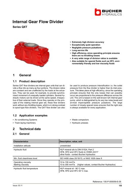
<strong>Internal</strong> <strong>Gear</strong> <strong>Flow</strong> <strong>Divider</strong><br />
Series QXT<br />
Extremely high division accuracy<br />
Exceptionally quiet operation<br />
Negligible pressure pulsations<br />
Long service life<br />
High efficiency, since operating principle ensures<br />
there are no throttling losses<br />
A very wide range of division ratios is available<br />
Also suitable for special fluids such as HFC, envi−<br />
ronmentally friendly and low viscosity fluids<br />
1 General<br />
1.1 Product description<br />
Series QXT flow dividers are internal gear units that can di−<br />
vide a flow into as many as four portions. The division ratios<br />
are constant and are unaffected by the loads at the actua−<br />
tors. They can be used, for example, to provide synchro−<br />
nised movement of unequally loaded cylinders. Several hydraulic<br />
motors can be driven at the same speed, irrespective<br />
of their external loads. Since they operate on the principle<br />
of the rotating internal gear set, these flow dividers<br />
work without any throttling losses, which is in strong contrast<br />
to spool−type flow dividers. The QXT flow divider can also<br />
be used to produce pressure intensification i.e. the outlet<br />
pressure from the flow divider is higher than its inlet pressure.<br />
This takes place at high efficiency, since the operating<br />
principle ensures that the only losses that can possibly<br />
occur are proportional to the pressure difference across the<br />
unit. The unit is based on the well−known QX internal gear<br />
pump, which is distinguished by its very low noise levels and<br />
al−most imperceptible pressure pulsations. The large<br />
number of closely spaced sizes ensures that the right size<br />
is always available for every application.<br />
1.2 Application examples<br />
Air conditioning Systems<br />
Track laying machinery<br />
Waste compactors<br />
Hydraulic presses<br />
2 Technical data<br />
2.1 General<br />
Characteristics<br />
Installation attitude<br />
Description, value, unit<br />
unrestricted<br />
Hydraulic fluid HLP mineral oils to DIN 51524, Part 2<br />
HFB, HFD and HFC fluids to VDMA 24317<br />
other fluids − contact Bucher Hydraulics<br />
Min. fluid cleanliness level ISO 4406 class 20/18/15, or NAS 1638 class 9<br />
Operating viscosity<br />
Starting viscosity<br />
Hydraulic fluid temperature<br />
10 to 100 mm 2 /s<br />
10 to 300 mm 2 /s (higher values, contact Bucher Hydraulics)<br />
HLP mineral oil − 80C max.<br />
HFB, HFD and HFC 50C max.<br />
Reference: 100−P−000059−E−05<br />
Issue: 03.11<br />
1/8
2.2 <strong>Flow</strong> dividers with outlet flows of equal sizes<br />
These operating data are valid for mineral oils with 42 mm 2 /s.<br />
Please contact Bucher if you require unequal outlet flows.<br />
Maximum inlet flow Q 0 max<br />
Type<br />
Outlet<br />
displacement<br />
cm 3 /U<br />
Cont./ Interm.<br />
pressure 1)<br />
bar<br />
Speed<br />
n max / n min<br />
min −1<br />
2 outlet<br />
flows<br />
l/min<br />
3 outlet<br />
flows 2)<br />
l/min<br />
4 outlet<br />
flows 2)<br />
l/min<br />
QXT22−005<br />
QXT22−006<br />
QXT22−008<br />
5<br />
6<br />
8<br />
250/320 6300/1250<br />
63<br />
80<br />
100<br />
95<br />
120<br />
150<br />
125<br />
160<br />
200<br />
QXT32−012<br />
QXT32−016<br />
12<br />
16<br />
250/320 5000/1000<br />
120<br />
160<br />
180<br />
240<br />
240<br />
320<br />
QXT42−025<br />
QXT42−032<br />
25<br />
32<br />
250/320 4000/800<br />
200<br />
250<br />
300<br />
380<br />
400<br />
500<br />
QXT52−050<br />
QXT52−063<br />
50<br />
63<br />
250/320 3200/630<br />
320<br />
400<br />
480<br />
600<br />
640<br />
800<br />
QXT62−100<br />
QXT62−125<br />
100<br />
125<br />
250/320 2500/500<br />
500<br />
630<br />
750<br />
950<br />
1000<br />
1260<br />
QXT82−200<br />
QXT82−250<br />
200<br />
250<br />
250/320 2000/400<br />
800<br />
1000<br />
1200<br />
1500<br />
1600<br />
2000<br />
1) Intermittent for max. 20 sec/min but not than 10% of the duty cycle 2) for 3 and 4 outlet flow please contact Bucher Hydraulics<br />
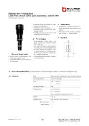
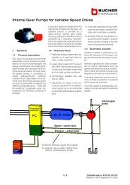
2.3 Choose the optimal flow divider<br />
These operating data are valid for mineral oils with 42 mm 2 /s.<br />
For the highest division accuracy as well as the lowest cost,<br />
choose the smallest possible flow divider running near its<br />
maximum speed. The speed n in rev/min is calculated from:<br />
Q 0 x 10<br />
n =<br />
3<br />
V 1 + V 2 + V 3 + . . .<br />
where Q 0 = inlet flow rate in l/min and V1 = outlet displacement<br />
in cm 3 /rev. The minimum permissible inlet flow rate is<br />
calculated from:<br />
Δp = [bar]<br />
16<br />
14<br />
12<br />
p 1 / Q 1 p 2 / Q 2<br />
V1 V2<br />
Q 0 / p 0<br />
Q0 min =<br />
n min<br />
n max<br />
x<br />
Q 0 max<br />
10<br />
8<br />
p 2 = p 1<br />
In the case of the flow dividers with unequal outlet displace−<br />
ments, use the largest displacement for determining n max ,<br />
the smallest for n min . Since rotary flow dividers are also<br />
pressure intensifiers, each outlet circuit must be provided<br />
with a pressure relief valve. Bucher Hydraulics series VT relief<br />
valves mount directly on the flow divider and are therefore<br />
particularly suitable (please request the data sheet<br />
100−D−402850).<br />
6<br />
4<br />
2<br />
0<br />
0<br />
0,2 0,4 0,6 0,8 1,0<br />
Q 0<br />
Q 0 max<br />
2/8<br />
100−P−000059−E−05 /03.11<br />
<strong>Internal</strong> <strong>Gear</strong> <strong>Flow</strong> <strong>Divider</strong> QXT
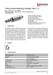
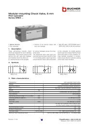
3 Performance curves<br />
These operating data are valid for mineral oils with 42 mm 2 /s.<br />
Tests carried out on a QXT flow divider, type 32−016/32−016,<br />
produced the results shown below. For the same speed,<br />
larger flow dividers have a better accuracy while smaller<br />
ones display a bigger difference between the two outlet<br />
flows. The division accuracy of the outlet flows Q1 and Q2<br />
depends mainly on the pressure difference between the two<br />
outlet lines and the ratio Q 0 / Q 0 max The pressure drop<br />
across the flow divider is dependent on Q 0 / Q 0 max Using<br />
the curves, the accuracy of flow division and the pressure<br />
drop can be optimised.<br />
Q2/Q0<br />
0,60<br />
0,55<br />
0,50<br />
p 2 0<br />
Q 0<br />
Q 0 max<br />
= 0,2<br />
100 200<br />
0,4<br />
0,6<br />
0,8<br />
1,0<br />
p 1 −p 2<br />
300 bar<br />
0,45<br />
0,40<br />
Q1/Q0<br />
Q 0<br />
Q 0 max<br />
= 0,2<br />
0,4<br />
1,0<br />
0,8<br />
0,6<br />
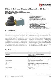
4 Dimensions<br />
4.1 For flow divider with 2 displacements<br />
Frame size 2 3 4 5 6 8<br />
J2 G 1 1 / 4 "<br />
thread<br />
E G 1 / 2 "<br />
thread<br />
G 1 1 / 2 "<br />
thread<br />
G 3 / 4 "<br />
thread<br />
2"<br />
2"<br />
2"<br />
G 2 1 / 2 "<br />
SAE J518 1) SAE J518 1) SAE J518 1) thread<br />
1"<br />
1 1 / 4 "<br />
1 1 / 2 "<br />
2"<br />
SAE J518 1) SAE J518 1) SAE J518 1) SAE J518 1)<br />
G M8x12 M8x12 M10x16 M10x20 M16x28 M20x30<br />
K2 102 129 159,5 190 230,5 282,5<br />
L2 204 258 319 380 461 565<br />
Z 50 60 62,5 78 97,5 125<br />
Q2 67 87 110,5 127 149 178,5<br />
Y 55 60 75 90 112 140<br />
T 85 107 133 177 220 275<br />
1) for SAE J518 code 61 / ISO 6162−1 pipe flange (see section 6.2)<br />
100−P−000059−E−05 /03.11<br />
<strong>Internal</strong> <strong>Gear</strong> <strong>Flow</strong> <strong>Divider</strong> QXT<br />
3/8
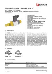
4.2 Frame size 2 − 3<br />
K2<br />
Q2<br />
L2<br />
Q2<br />
Y<br />
T<br />
Y<br />
Z<br />
Z<br />
1<br />
E<br />
E<br />
J2<br />
1 Mounting threads<br />
4 x dimensions ’G’ − both ends<br />
4.3 Frame size 4 − 6<br />
K2<br />
Q2<br />
L2<br />
Q2<br />
Y<br />
T<br />
Y<br />
E<br />
E<br />
Z<br />
Z<br />
1<br />
J2<br />
1 Mounting threads<br />
4 x dimensions ’G’ − both ends<br />
4/8<br />
100−P−000059−E−05 /03.11<br />
<strong>Internal</strong> <strong>Gear</strong> <strong>Flow</strong> <strong>Divider</strong> QXT
4.4 Frame size 8<br />
567<br />
283,5<br />
178,5 178,5<br />
140<br />
125 125<br />
180<br />
275<br />
140<br />
2" SAE 2" SAE<br />
1<br />
G 2 1/2"<br />
1 Mounting threads<br />
4 x dimensions ’G’ − both ends<br />
4.5 <strong>Flow</strong> divider with 3 displacements<br />
(please contact Bucher Hydraulics)<br />
E<br />
E<br />
E<br />
J3<br />
J2<br />
100−P−000059−E−05 /03.11<br />
<strong>Internal</strong> <strong>Gear</strong> <strong>Flow</strong> <strong>Divider</strong> QXT<br />
5/8
4.6 <strong>Flow</strong> divider with 4 displacements<br />
(please contact Bucher Hydraulics)<br />
E<br />
E<br />
E<br />
E<br />
J2<br />
J2<br />
5 Ordering code for 2 displacements<br />
Q<br />
X T 3 2 − 0 1 2 / 3 2 − 0 1 2 /<br />
Series<br />
QXT<br />
Frame size 2 / 3 / 4 / 5 / 6 / 8<br />
Pressure range 2 2<br />
Outlet displacement 005 − 250 (see section 2)<br />
Frame size 2 / 3 / 4 / 5 / 6 / 8<br />
Pressure range 2 2<br />
Outlet displacement 005 − 250 (see section 2)<br />
Special features (see section 5.2)<br />
6/8<br />
100−P−000059−E−05 /03.11<br />
<strong>Internal</strong> <strong>Gear</strong> <strong>Flow</strong> <strong>Divider</strong> QXT
5.1 Ordering example<br />
For dividers with 3 outlet flows:<br />
QXT22−005 / 22−005 / 22−005<br />
For dividers with 4 outlet flows:<br />
QXT62−100 / 62−100 / 62−100 / 62−100<br />
<strong>Flow</strong> divider combinations must contain the same frame<br />
sizes, pressure ranges and outlet flows.<br />
If 3, 4 or unequal flows are required, please contact<br />
Bucher Hydraulics<br />
5.2 Special features<br />
09 = seal substance out of FPM<br />
117 = port at outlet (E) in SAE J518 code 61 / ISO 6162I<br />
at assembly group 2+3<br />
6 Accessories<br />
6.1 Bolt−on valves − SAE J518 code 61 / ISO 6162−1 pattern<br />
Ordering details<br />
Pressure relief<br />
Symbols P T<br />
Pressure relief<br />
solenoid control<br />
Pressure relief<br />
proportional solenoid control<br />
S S<br />
S<br />
S<br />
A G DF / A G DH<br />
A G DA / ASDM<br />
A G DP<br />
P<br />
T<br />
P<br />
T<br />
M<br />
Z<br />
M<br />
Z<br />
M<br />
Z<br />
Ordering details<br />
Unloading valve<br />
Accumulator charging valve<br />
S S<br />
A GAF<br />
A G SF<br />
Symbols P T<br />
Z<br />
S = for pipe flange SAE J518<br />
code 61 (all sizes)<br />
G = with threaded port, G 1"<br />
(size QXT2, 3 and 4)<br />
M<br />
100−P−000059−E−05 /03.11<br />
<strong>Internal</strong> <strong>Gear</strong> <strong>Flow</strong> <strong>Divider</strong> QXT<br />
7/8
6.2 Pipe flange − high pressure type<br />
− up to 420 bar<br />
− SAE J518 code 61 / ISO 6162−1 pattern<br />
Threaded pipe flanges are spot−faced for pipe fittings.<br />
Material: ST37 / For Viton seals, contact Bucher Hydraulics<br />
Orderingnumber<br />
Ordering<br />
code<br />
Size D∅ E F H L R X Y Viton seal<br />
90 Shore<br />
’A’<br />
Retaining screws<br />
DIN912−12.9<br />
M [Nm]<br />
037000 RF 01−R08 G 1/2" 12,5 16 27 13 54 23 17,5 38 20,24x2,62 M8x30 30<br />
037010 RF 02−R10 G 3/4" 20 18 30 12 65 26 22,2 47,6 26,65x2,62 M10x30 60<br />
037020 RF 03−R11 G 1" 25 20 34 13 70 29 26,2 52,4 32,99x2,62 M10x35 60<br />
037030 RF 04−R12 G 1 1/4" 32 22 38 14 80 36 30,2 58,6 40,86x3,53 M10x40 60<br />
037040 RF 05−R13 G 1 1/2" 38 24 41 19 94 41 35,7 70 44,04x3,53 M12x45 120<br />
037050 RF 06−R14 G 2" 50 26 45 20 102 48 42,9 77,8 59,92x3,53 M12x50 120<br />
info.kl@bucherhydraulics.com<br />
www.bucherhydraulics.com<br />
2011 by Bucher Hydraulics GmbH, D−79771 Klettgau<br />
All rights reserved.<br />
Data is provided for the purpose of product description only, and must not be construed as warranted characteristics in the legal sense.<br />
The information does not relieve users from the duty of conducting their own evaluations and tests. Because the products are subject to<br />
continual improvement, we reserve the right to amend the product specifications contained in this catalogue.<br />
Classification: 420.245.370.<br />
8/8<br />
100−P−000059−E−05 /03.11<br />
<strong>Internal</strong> <strong>Gear</strong> <strong>Flow</strong> <strong>Divider</strong> QXT