EXPERIMENT 5 Series Resonance in AC Circuits Figure 1
EXPERIMENT 5 Series Resonance in AC Circuits Figure 1
EXPERIMENT 5 Series Resonance in AC Circuits Figure 1
You also want an ePaper? Increase the reach of your titles
YUMPU automatically turns print PDFs into web optimized ePapers that Google loves.
Physics 112 Laboratory Exp. 5 – <strong>Series</strong> <strong>Resonance</strong> <strong>in</strong> <strong>AC</strong> <strong>Circuits</strong> (2004 Fall)<br />
Note, <strong>in</strong> Equations (1)-(4) the maximum values of the <strong>AC</strong> currents and voltages are used rather<br />
than the effective values I and V. S<strong>in</strong>ce I = 0.707 i max and V = 0.707 v max , we are free to use either set<br />
of values. S<strong>in</strong>ce it is easier to obta<strong>in</strong> i max and V max from the screen of the oscilloscope, we use the<br />
maximum values here.<br />
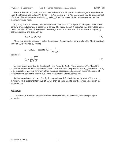
(X L - X C ) is the equivalent reactance between po<strong>in</strong>ts a and b <strong>in</strong> <strong>Figure</strong> 1. This part of the circuit<br />
consists of an <strong>in</strong>ductor and a capacitor <strong>in</strong> series. The m<strong>in</strong>us sign of X C <strong>in</strong>dicates that the voltage across<br />
the <strong>in</strong>ductor is 180° out of phase with the voltage across the capacitor. The maximum voltage V L+C<br />
between po<strong>in</strong>ts a and b is given by:<br />
V L+C = i max (X L -X C ) (6)<br />
There is a specific frequency, called the resonant frequency, f res , at which X L = X C . The theoretical<br />
value of f res is obta<strong>in</strong>ed by sett<strong>in</strong>g<br />
lead<strong>in</strong>g to<br />
X L = 2πf res L equal to X<br />
f res<br />
C<br />
1<br />
=<br />
2π<br />
f<br />
res<br />
C<br />
1 1<br />
= (7)<br />
2π<br />
LC<br />
At resonance, accord<strong>in</strong>g to Equation (5) and <strong>Figure</strong> 2, Z = R. Therefore, i max = V max /R and the<br />
current <strong>in</strong> the circuit has its maximum value. Also, Equation (6) predicts that V L+C = 0 s<strong>in</strong>ce X L - X C<br />
= 0. In practice, V L+C is a m<strong>in</strong>imum rather than zero at resonance because of the small amount of<br />
resistance between po<strong>in</strong>ts a and b due to the resistance of the <strong>in</strong>ductance coil.<br />
In this experiment, you will f<strong>in</strong>d f res for a particular RLC circuit by not<strong>in</strong>g where V L+C is a<br />
m<strong>in</strong>imum. This experimental value of f res will then be compared to the theoretical value given by<br />
Equation (7).<br />
Apparatus:<br />
Fixed-value <strong>in</strong>ductor, capacitance box, resistance box, <strong>AC</strong> ammeter, oscilloscope, signal<br />
generator.<br />
v.2004-sep-10 (IMG)<br />
2


