APS Technology | Wave Propagation Resistivity Sub (WPRâ¢)
APS Technology | Wave Propagation Resistivity Sub (WPRâ¢)
APS Technology | Wave Propagation Resistivity Sub (WPRâ¢)

Create successful ePaper yourself
Turn your PDF publications into a flip-book with our unique Google optimized e-Paper software.
<strong>Wave</strong> <strong>Propagation</strong><br />
<strong>Resistivity</strong> <strong>Sub</strong> (WPR )<br />
Measure ◆ Communicate ◆ Act <br />
MWD/LWD Sensors, Telemetry<br />
& Surface Systems<br />
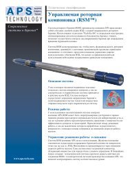
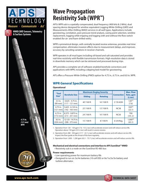
<strong>APS</strong>’s WPR sub is a spatially compensated, dual frequency (400 kHz & 2 MHz), dual<br />
spacing device designed for wireline-equivalent Logging-While-Drilling (LWD) and<br />
Measurements-After-Drilling (MAD) services in all well types. Applications include<br />
geosteering, correlation, pore pressure trend analysis, casing point selection, wireline<br />
replacement, logging while tripping and logging with and without the flow switch<br />
enabled (for air- and foam-drilled wells).<br />
WPR’s symmetrical design, with centrally located receive antennas, provides real-time<br />
compensation, eliminates invasion effects due to measurement delays, and improves<br />
accuracy by canceling variations in receiver channels.<br />
WPR operates in all mud types including oil-based and salt-saturated and provides<br />
real-time resistivity with flexible transmission formats. High-resolution data is stored<br />
in downhole memory which can be retrieved and processed during trips.<br />
<strong>APS</strong> provides a complete set of software-enabled borehole corrections and<br />
applications with WPR, including a dipping bed model for geosteering.<br />
<strong>APS</strong> offers a Pressure-While-Drilling (PWD) option for 4.75 in., 6.75 in. and 8.0 in. WPR.<br />
WPR General Specifications<br />
Operational<br />
4.75 in.<br />
(121 mm)<br />
WPR<br />
“Tool<br />
Size”<br />
3.5 in.<br />
(89 mm)<br />
4.75 in.<br />
(121 mm)<br />
6.75 in.<br />
(172 mm)<br />
8.0 in.<br />
(204 mm)<br />
Borehole Size<br />
4.625 - 4.75 in.<br />
(117 - 121 mm)<br />
5.625 - 6.125 in.<br />
(142 - 165 mm)<br />
8.375 - 9.875 in.<br />
(213 - 251 mm)<br />
12.125 - 14.75 in.<br />
(308 - 375 mm)<br />
Maximum Dogleg Severity<br />
Sliding<br />
Rotating<br />
Connection<br />
40˚/100 ft 16˚/100 ft 2 7/8 AOH<br />
25˚/100 ft 13˚/100 ft NC38<br />
24˚/100 ft 10˚/100 ft NC50<br />
15˚/100 ft 8˚/100 ft 6 5/8 Reg.<br />
Max. Flow<br />
Rate, gpm<br />
(L/sec)<br />
120 [1]<br />
(7.6)<br />
350 [2]<br />
(22.1)<br />
700<br />
(44.2)<br />
1,000 [3]<br />
(63.1)<br />
1. Operation from 120 - 150 gpm (7.6 - 9.5 L/sec) will accelerate erosion and will reduce service life.<br />
Operation above 150 gpm (9.5 L/sec) will result in severe erosion.<br />
2. Operation from 280 - 350 gpm (17.7 - 22.1 L/sec) will accelerate erosion and will reduce service life.<br />
Inspect the flow guide at the throat of the bore regularly.<br />
3. Operation from 1,000 - 1,200 gpm (63.1 - 75.7 L/sec) will accelerate erosion and will reduce service life.<br />
Mechanical and electrical connections and interface to <strong>APS</strong> SureShot MWD<br />
• <strong>Resistivity</strong> sub is a node on the SureShot RS-485 bus<br />
Power requirements<br />
• Low operating power for maximum battery life<br />
• Designed to run on 3x/4x batteries (10 cell DD) or 0x/1x/2x/3x battery and<br />
turbine alternator.<br />
www.aps-tech.com<br />
TECHNICAL DATA SHEET
Measure ◆ Communicate ◆ Act <br />
MWD/LWD Sensors, Telemetry<br />
& Surface Systems<br />
<strong>Wave</strong> <strong>Propagation</strong><br />
<strong>Resistivity</strong> <strong>Sub</strong> (WPR )<br />
Tool Programming and Data Dump port<br />
• Hatch cover for easy access via cable connection to allow tool programming and<br />
memory dump. Memory data dumps and tool programming can also be performed<br />
when the tool string is disconnected from the resistivity via the tool string lower end.<br />
32 MB integrated FLASH memory<br />
Environmental<br />
Operating Temperature<br />
Pressure<br />
Product Specifications<br />
0˚ to 302˚F; 347˚F option (-18˚ to 150˚C; 175˚C option)<br />
20,000 psi (138 MPa)<br />
Compensated <strong>Resistivity</strong> Measurements<br />
Frequency Measurement Range Accuracy<br />
2 MHz<br />
400 kHz<br />
Phase Difference<br />
Amplitude Ratio<br />
Phase Difference<br />
Amplitude Ratio<br />
Transmitter / Receiver Spacings<br />
0.1 – 3,000 ohm-m<br />
0.1 – 500 ohm-m<br />
0.1 – 1,000 ohm-m<br />
0.1 – 200 ohm-m<br />
± 1% [0.1 – 50 ohm-m]<br />
± 0.5 mmho/m [above 50 ohm-m]<br />
± 2% [0.1 – 25 ohm-m]<br />
± 1.0 mmho/m [above 25 ohm-m]<br />
± 1% [0.1 – 25 ohm-m]<br />
± 1.0 mmho/m [above 25 ohm-m]<br />
± 5% [0.1 – 10 ohm-m]<br />
± 5.0 mmho/m [above 10 ohm-m]<br />
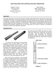
3.5 in.<br />
(89 mm)<br />
WPR<br />
Measure Point<br />
UH<br />
DH<br />
T 1 T 2 * R 1 R 2 T 3 * T 4<br />
in. -36.00 -22.50 -4.25 +4.25 +22.50 +36.00<br />
mm -914.4 -571.5 -107.9 +107.9 +571.5 +914.4<br />
* Not included in 3.5 in. size.<br />
Depth of Investigation, Vertical Resolution<br />
Headquarters ◆ Wallingford ◆ USA<br />
7 Laser Lane, Wallingford, CT 06492 USA<br />
Phone: 860-613-4450 ◆ Fax: 203-284-7428<br />
contact@aps-tech.com<br />
Houston ◆ USA<br />
15415 International Plaza Dr., Suite #150<br />
Houston, TX 77032 USA<br />
Phone: 281-847-3700<br />
Rev. 140604-vC.05<br />
Specifications subject to change without notice.<br />
© <strong>APS</strong> <strong>Technology</strong>, Inc. 2014<br />
www.aps-tech.com<br />
R f = 1 ohm-m<br />
R xo = 0.5 ohm-m<br />
Depth of Investigation<br />
Short Spacing<br />
Radius<br />
Long Spacing<br />
Radius<br />
Vertical<br />
Resolution**<br />
2 MHz Phase 21 in. (533 mm) 28 in. (711 mm) 8 in. (203 mm)<br />
400 kHz Phase 30 in. (762 mm) 39 in. (991 mm) 12 in. (305 mm)<br />
2 MHz Amplitude 34 in. (866 mm) 44 in. (1,118 mm) 8 in. (203 mm)<br />
400 kHz Amplitude 52 in. (1,321 mm) 66 in. (1,676 mm) 12 in. (305 mm)<br />
R f = 10 ohm-m<br />
R xo = 0.5 ohm-m<br />
Depth of Investigation<br />
Short Spacing<br />
Radius<br />
Long Spacing<br />
Radius<br />
Vertical<br />
Resolution**<br />
2 MHz Phase 26 in. (660 mm) 37 in. (940 mm) 8 in. (203 mm)<br />
400 kHz Phase 36 in. (914 mm) 49 in. (1,245 mm) 12 in. (305 mm)<br />
2 MHz Amplitude 40 in. (1,016 mm) 53 in. (1,346 mm) 8 in. (203 mm)<br />
400 kHz Amplitude 60 in. (1,524 mm) 76 in. (1,930 mm) 12 in. (305 mm)<br />
** 90% response in conductive beds.<br />
TECHNICAL DATA SHEET