DIRECT DRIVE COMPRESSOR - CCW-Tools
DIRECT DRIVE COMPRESSOR - CCW-Tools
DIRECT DRIVE COMPRESSOR - CCW-Tools

Create successful ePaper yourself
Turn your PDF publications into a flip-book with our unique Google optimized e-Paper software.
INSTRUCTIONS FOR:<br />
<strong>DIRECT</strong> <strong>DRIVE</strong> <strong>COMPRESSOR</strong><br />
MODEL NO: SA22503<br />
Thank you for purchasing a Sealey product. Manufactured to a high standard this product will, if used according to these instructions<br />
and properly maintained, give you years of trouble free performance.<br />
IMPORTANT: PLEASE READ THESE INSTRUCTIONS CAREFULLY. NOTE THE SAFE OPERATIONAL REQUIREMENTS, WARNINGS & CAUTIONS.<br />
USE THE PRODUCT CORRECTLY AND WITH CARE FOR THE PURPOSE FOR WHICH IT IS INTENDED. FAILURE TO DO SO MAY CAUSE<br />
DAMAGE OR PERSONAL INJURY AND WILL INVALIDATE THE WARRANTY. PLEASE KEEP INSTRUCTIONS SAFE FOR FUTURE USE.<br />
1. SAFETY INSTRUCTIONS<br />
1.1. ELECTRICAL SAFETY<br />
p WARNING! It is the responsibility of the owner and the operator to read, understand and comply with the following:<br />
You must check all electrical products, before use, to ensure that they are safe. You must inspect power cables, plugs, sockets and<br />
any other connectors for wear or damage. You must ensure that the risk of electric shock is minimised by the installation of<br />
appropriate safety devices. A Residual Current Circuit Breaker (RCCB) should be incorporated in the main distribution board. We also<br />
recommend that a Residual Current Device (RCD) is used. It is particularly important to use an RCD with portable products that are<br />
plugged into a supply which is not protected by an RCCB. If in any doubt consult a qualified electrician. You may obtain a Residual<br />
Current Device by contacting your Sealey dealer.<br />
You must also read and understand the following instructions concerning electrical safety.<br />
1.1.1. The Electricity at Work Act 1989 requires that all portable electrical appliances, if used on business premises, are tested by a qualified<br />
electrician, using a Portable Appliance Tester (PAT), at least once a year.<br />
1.1.2. The Health & Safety at Work Act 1974 makes owners of electrical appliances responsible for the safe condition of those appliances<br />
and the safety of the appliance operators. If in any doubt about electrical safety, contact a qualified electrician.<br />
1.1.3. Ensure that the insulation on all cables and on the appliance is safe before connecting it to the power supply. See 1.1.1. and 1.1.2.<br />
and use a Portable Appliance Tester.<br />
1.1.4. Ensure that cables are always protected against short circuit and overload.<br />
1.1.5. Regularly inspect power supply cables and plugs for wear or damage and check all connections to ensure that none is loose.<br />
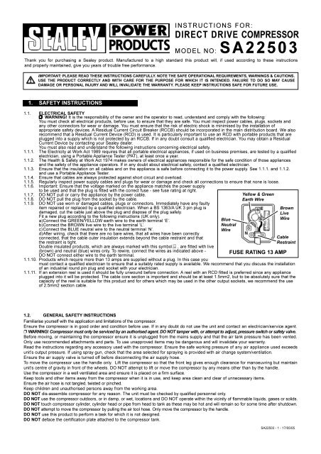
1.1.6. Important: Ensure that the voltage marked on the appliance matches the power supply<br />
to be used and that the plug is fitted with the correct fuse - see fuse rating at right.<br />
1.1.7. DO NOT pull or carry the appliance by the power cable.<br />
1.1.8. DO NOT pull the plug from the socket by the cable.<br />
1.1.9. DO NOT use worn or damaged cables, plugs or connectors. Immediately have any faulty<br />
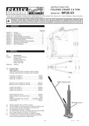
item repaired or replaced by a qualified electrician. When a BS 1363/A UK 3 pin plug is<br />
damaged, cut the cable just above the plug and dispose of the plug safely.<br />
Fit a new plug according to the following instructions (UK only).<br />
a)Connect the GREEN/YELLOW earth wire to the earth terminal ‘E’.<br />
b)Connect the BROWN live wire to the live terminal ‘L’.<br />
c)Connect the BLUE neutral wire to the neutral terminal ‘N’.<br />
d)After wiring, check that there are no bare wires, that all wires have been correctly<br />
connected, that the cable outer insulation extends beyond the cable restraint and that<br />
the restraint is tight.<br />
Double insulated products, which are always marked with this symbol , are fitted with live<br />
(brown) and neutral (blue) wires only. To rewire, connect the wires as indicated above -<br />
DO NOT connect either wire to the earth terminal.<br />
1.1.10. Products which require more than 13 amps are supplied without a plug. In this case you<br />
Blue<br />
Neutral<br />
Wire<br />
Yellow & Green<br />
Earth Wire<br />
Brown<br />
Live<br />
Wire<br />
Cable<br />
Restraint<br />
FUSE RATING 13 AMP<br />
must contact a qualified electrician to ensure that a suitably rated supply is available. We recommend that you discuss the installation<br />
of an industrial round pin plug and socket with your electrician.<br />
1.1.11. If an extension reel is used it should be fully unwound before connection. A reel with an RCD fitted is preferred since any appliance<br />
plugged into it will be protected. The cable core section is important and should be at least 1.5mm2, but to be absolutely sure that the<br />
capacity of the reel is suitable for this product and for others which may be used in the other output sockets, we recommend the use<br />
of 2.5mm2 section cable.<br />
1.2. GENERAL SAFETY INSTRUCTIONS<br />
Familiarise yourself with the application and limitations of the compressor.<br />
Ensure the compressor is in good order and condition before use. If in any doubt do not use the unit and contact an electrician/service agent.<br />
p WARNING! Compressor must only be serviced by an authorised agent. DO NOT tamper with, or attempt to adjust, pressure switch or safety valve.<br />
Before moving, or maintaining the compressor ensure it is unplugged from the mains supply and that the air tank pressure has been vented.<br />
Only use recommended attachments and parts. To use unapproved items may be dangerous and will invalidate your warranty.<br />
Read the instructions regarding any accessory used with the compressor. Ensure the safe working pressure of any air appliance used exceeds<br />
unit’s output pressure. If using spray gun, check that the area selected for spraying is provided with air change system/ventilation.<br />
Ensure the air supply valve is turned off before disconnecting the air supply hose.<br />
To move the compressor use the handle only. Lift the compressor so that the front leg gives enough clearance for manoeuvring but maintain<br />
unit’s centre of gravity in front of the wheels. DO NOT attempt to lift or move the compressor by any means other than by the handle.<br />
Use the compressor in a well ventilated area and ensure it is placed on a firm surface.<br />
Keep tools and other items away from the compressor when it is in use, and keep area clean and clear of unnecessary items.<br />
Ensure the air hose is not tangled, twisted or pinched.<br />
Keep children and unauthorised persons away from the working area.<br />
DO NOT dis-assemble compressor for any reason. The unit must be checked by qualified personnel only.<br />
DO NOT use the compressor outdoors, or in damp, or wet, locations and DO NOT operate within the vicinity of flammable liquids, gases or solids.<br />
DO NOT touch compressor cylinder, cylinder head or pipe from head to tank as these may be hot and will remain so for some time after shutdown.<br />
DO NOT attempt to move the compressor by pulling the air tool hose. Only move the compressor by the handle.<br />
DO NOT use this product to perform a task for which it is not designed.<br />
DO NOT deface the certification plate attached to the compressor tank.<br />
SA22503 - 1 - 17/05/05
DO NOT cover the compressor or restrict air flow around the machine whilst operating.<br />
s DANGER! DO NOT direct the output jet of air towards people or animals.<br />
DO NOT operate the compressor without an air filter.<br />
DO NOT allow anyone to operate the compressor unless they have received full instructions.<br />
p WARNING! The air tank is a pressure vessel and the following safety measures apply:<br />
DO NOT tamper with the safety valve and DO NOT modify or alter the tank in any way and DO NOT strap anything to the tank.<br />
DO NOT subject the tank to impact, vibration or to heat and DO NOT allow contact with abrasives or corrosives.<br />
DO drain condensation from tank daily and inspect inside walls for corrosion every three months and have a detailed tank inspection<br />
carried out annually.<br />
The tank shell must not fall below the certified thickness at any point.<br />
p WARNING! If an electrical fuse blows, ensure it is replaced with an identical fuse type and rating.<br />
When not in use, store the compressor carefully in a safe, dry, childproof location.<br />
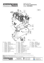
2. INTRODUCTION & SPECIFICATIONS<br />
Aluminium cylinders with cast iron liners give reduced weight and improved resistance to wear. Suitable for general-purpose workshop<br />
applications. Pump head directly coupled to heavy-duty induction motor for reliable operation. Precision welded receiver tank manufactured to<br />
meet Pressure Vessel Directive 87/404/EEC. Fitted with fully automatic pressure cut-out switch, air regulator and tank and supply pressure<br />
gauges. Supplied with handle and wheels for easy manoeuvrability. Fitted with ASTA/BS approved non-rewirable plug.<br />
2.1. Specification<br />
Model No . . . . . . . . . . . . . . . . SA22503<br />
Motor Output . . . . . . . . . . . . . . 3.0hp<br />
Voltage/Phase . . . . . . . . . . . . . 230V - 1ph<br />
Input Current . . . . . . . . . . . . . . 9.3A<br />
Piston Displacement . . . . . . . . 12.6cfm<br />
Max Free Air Delivery . . . . . . . 9.2cfm<br />
Tank Capacity . . . . . . . . . . . . . 50ltr<br />
Max. Pressure. . . . . . . . . . . . . 116psi/8bar<br />
fig. 1<br />
fig. A<br />
fig. 2<br />
3. PREPARATION<br />
3.1. Remove compressor from packaging and inspect for any shortages or damage. If anything is found to be missing or damaged contact<br />
your supplier.<br />
3.2. Save the packing material for future transportation of the compressor. We recommend that you store the packing in a safe location, at<br />
least for the period of the guarantee. Then, if necessary, it will be easier to send the compressor to the service centre.<br />
3.3. Confirm that the mains voltage corresponds with the voltage shown on the compressor data plate.<br />
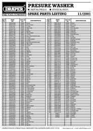
3.4 Assemble the wheels (fig.A-X) and rubber feet (fig.A-Y) to the main frame using using the nuts, bolts and washers supplied.<br />
3.5. The compressor should be operated on a flat surface, or one that does not exceed 15 O either transversely or longitudinally (fig.1), and<br />
should be in a position that allows good air circulation around the unit.<br />
p WARNING! The compressor is shipped without oil in the pump. Do not start the compressor until it has been filled with oil (see below).<br />
3.6. Remove the plastic transit plug from the oil filler hole and pour in the recommended oil. (See section 5.7).<br />
3.7. Before using the compressor check the oil level by refering to the oil sight glass (fig.2-C). If the oil level is not up to the red centre<br />
mark it should be further topped up. Screw the filler/breather cap into the aperture as shown in fig.2B.<br />
3.8 Screw the back half of a filter unit into the downward facing port openings in each head as shown in fig.2-A. Place a filter cover over<br />
each threaded rod protruding from the back half of the filter and secure each with a wing nut. Refer also to fig.4.<br />
4. OPERATION<br />
p WARNING! Ensure that you have read, understood and apply Section 1 safety instructions.<br />
4.1. IMPORTANT. The use of extension leads to connect this compressor to the mains is not recommended as the resulting<br />
voltage drop reduces motor, and therefore pump, performance.<br />
4.2. Take care when selecting tools for use with the compressor. Air tool manufacturers normally express the volume of air<br />
required to operate a tool in cubic feet per minute (cfm). This refers to free air delivered by the compressor (‘air out’) which<br />
varies according to the pressure setting. Do not confuse this with the compressor displacement which is the air taken in by<br />
the compressor (‘air in’). ‘Air out’ is always less than ‘air in’ - due to losses within the compressor .<br />
SA22503 - 1 - 17/05/05
4.3 STARTING THE <strong>COMPRESSOR</strong>.<br />
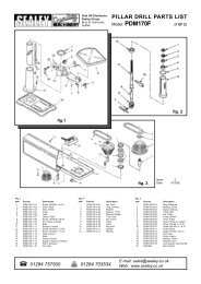
4.3.1 Your compressor is fitted with a push/pull type of ON/OFF switch.<br />
fig. 3<br />
To turn the compressor ‘ON’ pull the switch knob upwards. To turn the<br />
compressor ‘OFF’ push the knob downwards.(See fig.3-1)<br />
4.3.2 Check that the ON/OFF switch is in the “OFF” position, the regulator tap (fig.3-3) is<br />
closed (Zero ‘0’ bar), and air tap (fig.3-5) is OFF.<br />
4.3.3 Plug mains lead into mains supply and start the compressor by pulling the<br />
switch knob upwards.<br />
4.3.4 When starting the compressor for the first time, leave it running for several minutes<br />
with the air tap (fig.3-5) open to ensure good distribution of the lubricating oil. Turn<br />
the compressor off and close the air tap. Restart the compressor and leave it<br />
running with air tap (fig.3-5) closed and regulator (fig.3-3) set to maximum<br />
pressure. Make sure that pressure in the tank rises and that the compressor stops<br />
automatically when the max. pressure value allowed - written on the specification<br />
plate and shown on the gauge (fig.3-7) - is achieved. The compressor will now<br />
operate automatically. The pressure switch (fig.3-2) stops the motor when the<br />
maximum tank pressure is reached and restarts it when pressure falls below the<br />
minimum threshold - approx. 2 bar (29psi) less than the maximum pressure.<br />
4.3.5 Stop the compressor by pushing the switch knob (See fig.3-1) downwards. The compressed air inside the compressor head will flow<br />
out, making the restart easier and preventing the motor from being damaged. DO NOT, other than in an emergency, stop the<br />
compressor by switching off the mains socket, or by pulling the plug out, as the pressure relief will not then occur and motor damage<br />
may result upon restart.<br />
When the compressor runs correctly and is stopped correctly there will be:<br />
(a) a whistle of compressed air when the motor stops,<br />
(b) a protracted whistle (about 20-25 seconds) when the compressor starts with no pressure in the tank.<br />
4.3.6 The output pressure is regulated by the pressure regulator (fig.3-3). Turn the knob clockwise to increase pressure and anticlockwise to<br />
reduce it . The knob can be locked at any required setting by tightening the locking ring (fig.3-4) up against the underside of the knob.<br />
To determine the correct working pressure for any piece of equipment check the corresponding manual. When the compressor is not<br />
being used set the regulated pressure to zero so as to avoid damaging the pressure reducer.<br />
NOTE: a) If the motor does not cut in and out, but runs continuously when using an air appliance, the capacity of the compressor may be<br />
too small for the equipment or tool.<br />
b) The larger gauge (fig.3-7) indicates the pressure inside the main tank. The smaller gauge (fig.3-6) indicates the pressure supplied to<br />
the air equipment. Should the pressure in the main tank exceed the pre-set switch (fig.3-2) maximum, the safety valve (fig.3.8) will activate.<br />
WARNING! For this reason DO NOT tamper with, or adjust, the switch or safety valve.<br />
4.3.7 The compressor motor has a thermal cut-out which stops the motor if it gets too hot. The motor will restart again automatically when it<br />
has cooled down after 15 to 20 minutes. There is also an electrical overload switch in the connection box on top of the motor (see<br />
fig.A-X) The reset button is on the side of the box.<br />
5. MAINTENANCE<br />
In order to keep the compressor in good working condition, periodic maintenance is essential.<br />
p WARNING! Before performing any maintenance operation, switch off the compressor, disconnect from electricity supply and<br />
release all air from the tank.<br />
IMPORTANT! Failure to carry out maintenance tasks may invalidate the warranty on your compressor.<br />
5.1. Operations to be carried out after the first 5 working hours:<br />
a) Check that all bolts/nuts are tight, particularly those retaining the crank case<br />
and cylinder head.<br />
fig. 4<br />
5.2. Operations to be carried out after the first 50 working hours:<br />
b) Replace the lubricating oil - see para 5.5.<br />
5.3. Operations to be carried out daily:<br />
a) Drain condensation by opening the valve located under the tank (fig.5). Place<br />
a container under the valve and open the valve by turning anticlockwise.<br />
5.4. Operations to be carried out every 100 hours<br />
(or more frequently, if the compressor operates in a very dusty atmosphere):<br />
a) Check oil level and, if necessary, top up.<br />
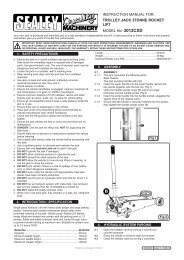
b) Remove the filter elements (See fig.4) and clean with compressed air. (Wear<br />
eye protection). Do not operate the compressor without the filter as foreign<br />
bodies or dust could seriously damage the pump.<br />
c) Check for oil leaks<br />
5.5. Operations to be carried out every 200 hours:<br />
a) Replace the lubricating oil. For oil specifications see 5.7.<br />
Remove the oil filler/breather plug (see fig.2-B) then unscrew oil sight glass (see fig.2-C) and drain the oil into a container.<br />
Drain when the compressor is hot so that oil drains rapidly and completely. Incline compressor to ensure complete drainage.<br />
Replace oil sight glass and refill through the oil filler/breather aperture. Do not overfill. Replace filler/breather plug.<br />
b) Check the automatic cut-out at max. pressure and the automatic cut-in at 2 bar below.<br />
p WARNING! Never mix different oils and do not use non-detergent/low quality oils as the<br />
compressor may be damaged.<br />
fig. 5<br />
p WARNING! Dispose of waste oil only in accordance with local authority requirements.<br />
5.6. Operations to be carried out every 500 hours:<br />
a) Replace air filter. (See fig.4. )<br />
b) Check all tube fittings and electrical connections.<br />
c) Inspect pressure tank inside and out for damage or corrosion.<br />
5.7. Recommended oils<br />
Recommended oil for compressors, suitable for room temperatures ranging from +5 O C to +25 O C.<br />
SEALEY CPO or equivalent SAE 40 compressor oil.<br />
Room temperature below +5 O C: SAE 20 compressor oil.<br />
SA22503 - 1 - 17/05/05<br />
Approximate oil capacity: 0.16 litres.
5.8. Scheduled maintenance table<br />
Maintenance<br />
Operations<br />
Drain condensation<br />
Check oil level<br />
Clean intake filter<br />
Check for oil leaks<br />
Check cut-out<br />
Replace oil<br />
General cleaning of<br />
compressor<br />
Internal & external<br />
inspection of tank<br />
Replace air filter<br />
Check tube fittings and<br />
electrical connections<br />
Daily<br />
100 hrs.<br />
•<br />
•<br />
•<br />
•<br />
200 hrs.<br />
•<br />
•<br />
•<br />
500 hrs.<br />
•<br />
•<br />
•<br />
fig. 6<br />
6. TROUBLE SHOOTING<br />
Fault Cause Remedy<br />
Pressure drop in the tank<br />
Pressure switch valve leaks when compressor is idle<br />
Air leaks at connections<br />
Non-return valve seal defective<br />
Run compressor to max. pressure, switch off.<br />
Brush soap solution over connections and look for<br />
bubbles. Tighten connections showing leaks.<br />
If problem persists contact Authorised Service Agent.<br />
Empty the air tank, remove the non-return valve cap<br />
‘3’ (fig.6) and clean, or, if necessary, replace,<br />
the seal ‘1 ’.<br />
Compressor stops and does not restart Motor failure Contact Authorised Service Agent.<br />
Compressor does not stop at max. pressure Pressure switch fault Contact Authorised Service Agent.<br />
Compressor does not stop at max. pressure<br />
Filter clogged<br />
Head gasket or valve fault<br />
Replace filter element.<br />
Contact Authorised Service Agent.<br />
Compressor noisy with metallic knock Bearing or piston damage Contact Authorised Service Agent.<br />
Declaration of Conformity We, the sole UK importer, declare that the product listed below is in conformity with the following<br />
standards and directives.<br />
The construction file for this product is held by the<br />
<strong>DIRECT</strong> <strong>DRIVE</strong> <strong>COMPRESSOR</strong><br />
Manufacturer and may be inspected, by a national authority,<br />
upon request to Jack Sealey Ltd.<br />
Models: SA22503<br />
87/404/EEC Pressure Vessel Directive<br />
89/336/EEC EMC Directive<br />
73/23/EEC LV Directive<br />
98/37/EC Machinery Directive<br />
93/68/EEC CE Marking Directive<br />
Signed by Mark Sweetman 18th MAY 2005<br />
For Jack Sealey Ltd. Sole UK importer of Sealey Power Products.<br />
NOTE: It is our policy to continually improve products and as such we reserve the right to alter data, specifications and component parts without prior notice.<br />
IMPORTANT: No liability is accepted for incorrect use of this equipment.<br />
WARRANTY: Guarantee is 12 months from purchase date, proof of which will be required for any claim.<br />
INFORMATION: For a copy of our latest catalogue and promotions call us on 01284 757525 and leave your full name and address, including postcode.<br />
Sole UK Distributor<br />
Sealey Group,<br />
Bury St. Edmunds, Suffolk.<br />
01284 757500<br />
www.sealey.co.uk<br />
01284 703534 email sales@sealey.co.uk<br />
Web<br />
SA22503 - 1 - 17/05/05