important: please read these instructions carefully ... - CCW-Tools
important: please read these instructions carefully ... - CCW-Tools
important: please read these instructions carefully ... - CCW-Tools

Create successful ePaper yourself
Turn your PDF publications into a flip-book with our unique Google optimized e-Paper software.
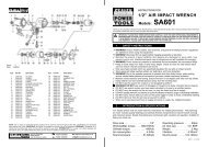
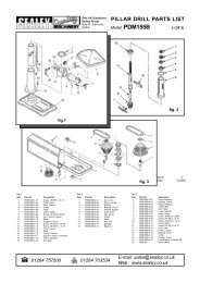
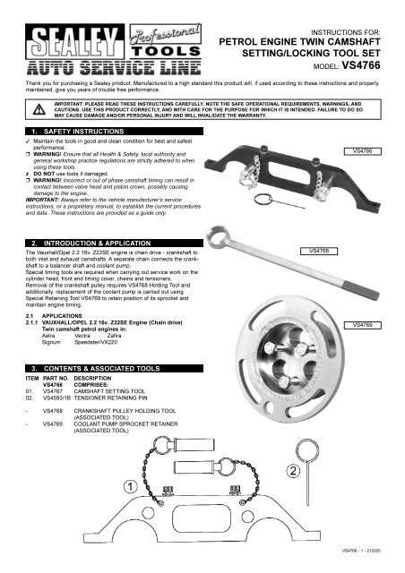
INSTRUCTIONS FOR:PETROL ENGINE TWIN CAMSHAFTSETTING/LOCKING TOOL SETMODEL: VS4766Thank you for purchasing a Sealey product. Manufactured to a high standard this product will, if used according to <strong>these</strong> <strong>instructions</strong> and properlymaintained, give you years of trouble free performance.IMPORTANT: PLEASE READ THESE INSTRUCTIONS CAREFULLY. NOTE THE SAFE OPERATIONAL REQUIREMENTS, WARNINGS, ANDCAUTIONS. USE THIS PRODUCT CORRECTLY, AND WITH CARE FOR THE PURPOSE FOR WHICH IT IS INTENDED. FAILURE TO DO SOMAY CAUSE DAMAGE AND/OR PERSONAL INJURY AND WILL INVALIDATE THE WARRANTY.1. SAFETY INSTRUCTIONS3 Maintain the tools in good and clean condition for best and safestperformance.p WARNING! Ensure that all Health & Safety, local authority andgeneral workshop practice regulations are strictly adhered to whenusing <strong>these</strong> tools.7 DO NOT use tools if damaged.p WARNING! Incorrect or out of phase camshaft timing can result incontact between valve head and piston crown, possibly causingdamage to the engine.IMPORTANT: Always refer to the vehicle manufacturer’s service<strong>instructions</strong>, or a proprietary manual, to establish the current proceduresand data. These <strong>instructions</strong> are provided as a guide only.VS47662. INTRODUCTION & APPLICATIONThe Vauxhall/Opel 2.2 16v. Z22SE engine is chain drive - crankshaft toboth inlet and exhaust camshafts. A separate chain connects the crankshaftto a balancer shaft and coolant pump.Special timing tools are required when carrying out service work on thecylinder head, front end timing cover, chains and tensioners.Removal of the crankshaft pulley requires VS4768 Holding Tool andadditionally, replacement of the coolant pump is carried out usingSpecial Retaining Tool VS4769 to retain position of its sprocket andmaintain engine timing.VS47682.1 APPLICATIONS2.1.1 VAUXHALL/OPEL 2.2 16v. Z22SE Engine (Chain drive)Twin camshaft petrol engines in:Astra Vectra ZafiraSignum Speedster/VX220VS47693. CONTENTS & ASSOCIATED TOOLSITEM PART NO. DESCRIPTIONVS4766 COMPRISES:01. VS4767 CAMSHAFT SETTING TOOL02. VS4593/1B TENSIONER RETAINING PIN- VS4768 CRANKSHAFT PULLEY HOLDING TOOL(ASSOCIATED TOOL)- VS4769 COOLANT PUMP SPROCKET RETAINER(ASSOCIATED TOOL)VS4766 - 1 - 210205
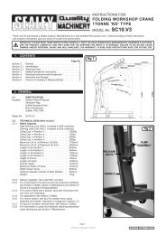
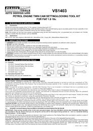
4. OPERATING INSTRUCTIONS4.1 TIMING CHECK4.1.1 VS4767 Setting Tool is required to determine correct camshafttiming.4.1.2 Remove air filter housing, intake pipe and engine vent hose.4.1.3 Relieve fuel pressure and detach fuel line, evaporator andignition module.4.1.4 Detach wiring harness and coolant pipe in order to remove thecam covers.4.1.5 Remove auxiliary belt and turn the crankshaft <strong>carefully</strong>, in thenormal direction of engine rotation, to set the 4th cylinder at TDC.Note: The cam lobes on both camshafts over this cylinder should pointupwards.4.2 CAMSHAFT SETTING TOOL (VS4767)4.2.1 Fix VS4767 Camshaft Setting Tool in place using the twosecuring screws provided.4.2.2 Insert both 'positioning pins' through the holes in the main bodyof the Tool and into the timing holes in the inlet and exhaustcamshaft sprockets.4.2.3 If the 'positioning pins' cannot enter the designated camshaftsprocket holes, timing will require adjustment.4.3 TIMING ADJUSTMENT4.3.1 When service work has required the dismantling/removal ofchains, sprockets and tensioners, engine timing will need to bere-established. 'Timing adjustment' requires the same procedure.4.3.2 Fix VS4767 Camshaft Setting Tool in place using the retainingscrews provided.4.3.3 Set the 4th cylinder at TDC (cam lobes should point upwards).4.2Upper Sliding Rail4.34.4 UPPER SLIDING RAIL - CHAIN TENSIONER4.4.1 Remove the upper sliding rail and remove the chain tensionerfrom the timing chain.Note: The tensioner should be of a type with marks on the hexagon. Ifnot it is likely a new tensioner and rail will be required.4.4.2 Remove the EXHAUST camshaft sprocket, counter-holding thecamshaft via the hexagon section on the camshaft.Chain TensionerVS4766 - 1 - 210205
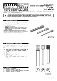
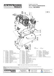
4.4.3 Adjust the position of the INLET camshaft sprocket, turning thecamshaft via the hexagon section, until the 'positioning pin' ofVS4767 can be inserted into the designated timing hole in thesprocket.4.4.4 Position the timing chain on the sprocket so that the COPPERcoloured link is located at the "INT" mark on the sprocket.4.4.5 Position the SILVER coloured link onto the exhaust camshaftsprocket at the "EXH" mark, offer up the exhaust camshaftsprocket to the exhaust camshaft and turn the camshaft(at hexagon) until the sprocket can be fitted to the camshaft.4.4.6 Ensure that the 'positioning pins' of VS4767 Setting Tool can beinserted in to the designated holes in both sprockets.4.4.7 Withdraw the 'positioning pins' and tighten the exhaust sprocketbolt whilst counter-holding the camshaft at the hexagon section.4.4.8 Replace seal rings of chain tensioner and pre-tension it by pullingout the piston, clamping it vertically upwards in a vice and lockingthe inner piston at last indent, by turning to the right.4.4.9 Re-install piston in housing and install the tensioner in engine.IMPORTANT: Ensure the tensioner is activated by pushing thetension rail or chain against it.4.4.10 Turn the crankshaft twice returning the crankshaft to mark andthe 4th cylinder to TDC.4.4.11 Push the 'positioning pins' into the holes in the camshaftsprockets to check engine timing is correct.4.4.12 Remove Tool and fit the upper sliding rail.4.4.34.54.5 CRANKSHAFT PULLEY HOLDING TOOL(VS4768 Associated Tool - not included in kit)4.5.1 Any service work requiring removal of the front lower cover willrequire the crankshaft pulley to be removed.4.5.2 As it will be necessary to remove engine mounting for <strong>these</strong>applications, the engine must be supported from below.4.5.3 Use VS4768 Holding Tool to counter-hold the crank pulley whilstreleasing and tightening the centre bolt.Note: DO NOT attempt to counter-hold the crankshaft/engine usingtiming tools or in any other way.4.6 BALANCER SHAFT TENSIONER4.6.1 To remove the balancer shaft timing chain the tensioner must beremoved.4.6.2 Before re-fitting the tensioner, the plunger must be compressedinto the body and retained.4.6.3 Use Retaining Pin VS4593/1B by turning the tensioner plungerclockwise, to retract and insert Pin VS4593/1B to retain.4.6.4 Remove the Pin to reactivate the tensioner once fitted.4.6VS4766 - 1 - 210205
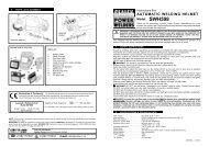
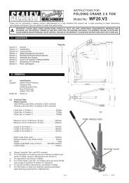
4.7 COOLANT PUMP REPLACEMENT(VS4769 Associated Tool - not included in kit)4..1 The coolant pump on the Z22SE engine can be replaced withoutthe need to disassemble the front end, allowing the engine timingposition to be maintained.4.7.2 A service cover is provided on the front cover to allow RetainerVS4769 to be fitted to hold the coolant pump sprocket in position,whilst the coolant pump is removed/replaced.4.7.3 Remove upper timing cover, manifold heat shield and oxygensensor wiring harness plug.4.7.4 Remover auxiliary belt and release pump drain bolt and draincoolant.4.7.5 Disconnect wiring harness plug from coolant temp. sensor anddetach coolant hose from thermostat housing and heater hosefrom radiator.4.7.6 Remove thermostat housing and pull it, with pipe, out of coolantpump.4.7.7 Close drain bolt and remove coolant pump cover.4.7.8 Remove the pump front service cover (4 bolts).4.74.7.9 Loosely attach VS4769 Retainer using two of the service coverbolts in the outer slotted holes of the Tool.4.7.10 Using the 3 centre attaching bolts supplied with the Tool, secureVS4769 Retainer to the coolant pump sprocket.4.7.11 Tighten the outer bolts to firmly fix the Tool in place. Releasethe 3 bolts which retain the coolant pump to the sprocket.4.7.12 Remove coolant pump.4.7.13 The engine timing is not disturbed as the chain is retained, inplace, on the pump sprocket.4.7.14 Replace pump, re-fit the bolts retaining the pump to its sprocketand remove VS4769 Retainer Tool.4.7.9NOTE: It is our policy to continually improve products and as such we reserve the right to alter data, specifications and component parts withoutprior notice. IMPORTANT: No liability is accepted for incorrect use of this equipment. WARRANTY: Guarantee is 12 months from purchase date,proof of which will be required for any claim. INFORMATION: For a copy of our latest catalogue and promotions call us on 01284 757525 andleave your full name and address, including postcode.Sole UK Distributor, Sealey Group, Bury St. Edmunds, Suffolk.01284 757500 01284 703534 www.sealey.co.uksales@sealey.co.ukWebemailVS4766 - 1 - 210205