X-Ray Generator (Rigaku RU-H2R) Operating Procedure
X-Ray Generator (Rigaku RU-H2R) Operating Procedure
X-Ray Generator (Rigaku RU-H2R) Operating Procedure

Create successful ePaper yourself
Turn your PDF publications into a flip-book with our unique Google optimized e-Paper software.
Created by Thayumanasamy Somasundaram<br />
Created on 5/11/2004 12:51:00 PM<br />
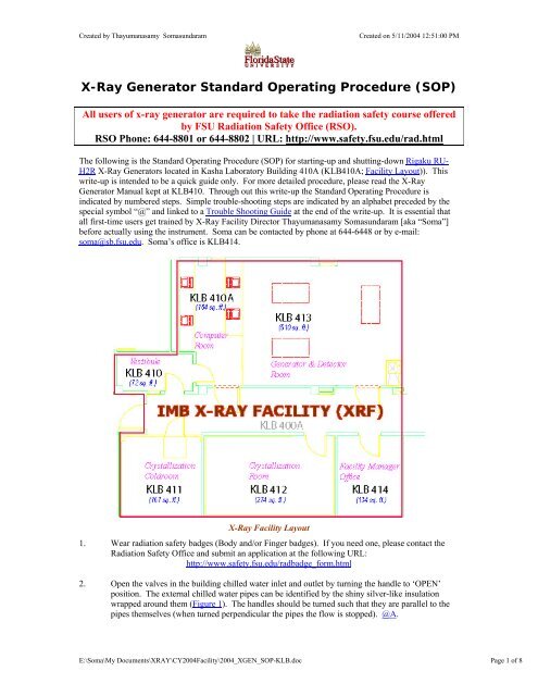
X-<strong>Ray</strong> <strong>Generator</strong> Standard <strong>Operating</strong> <strong>Procedure</strong> (SOP)<br />
All users of x-ray generator are required to take the radiation safety course offered<br />
by FSU Radiation Safety Office (RSO).<br />
RSO Phone: 644-8801 or 644-8802 | URL: http://www.safety.fsu.edu/rad.html<br />
The following is the Standard <strong>Operating</strong> <strong>Procedure</strong> (SOP) for starting-up and shutting-down <strong>Rigaku</strong> <strong>RU</strong>-<br />
<strong>H2R</strong> X-<strong>Ray</strong> <strong>Generator</strong>s located in Kasha Laboratory Building 410A (KLB410A; Facility Layout)). This<br />
write-up is intended to be a quick guide only. For more detailed procedure, please read the X-<strong>Ray</strong><br />
<strong>Generator</strong> Manual kept at KLB410. Through out this write-up the Standard <strong>Operating</strong> <strong>Procedure</strong> is<br />
indicated by numbered steps. Simple trouble-shooting steps are indicated by an alphabet preceded by the<br />
special symbol “@” and linked to a Trouble Shooting Guide at the end of the write-up. It is essential that<br />
all first-time users get trained by X-<strong>Ray</strong> Facility Director Thayumanasamy Somasundaram [aka “Soma”]<br />
before actually using the instrument. Soma can be contacted by phone at 644-6448 or by e-mail:<br />
soma@sb.fsu.edu. Soma’s office is KLB414.<br />
X-<strong>Ray</strong> Facility Layout<br />
1. Wear radiation safety badges (Body and/or Finger badges). If you need one, please contact the<br />
Radiation Safety Office and submit an application at the following URL:<br />
http://www.safety.fsu.edu/radbadge_form.html<br />
2. Open the valves in the building chilled water inlet and outlet by turning the handle to ‘OPEN’<br />
position. The external chilled water pipes can be identified by the shiny silver-like insulation<br />
wrapped around them (Figure 1). The handles should be turned such that they are parallel to the<br />
pipes themselves (when turned perpendicular the pipes the flow is stopped). @A.<br />
E:\Soma\My Documents\XRAY\CY2004Facility\2004_XGEN_SOP-KLB.doc Page 1 of 8
Created by Thayumanasamy Somasundaram<br />
Created on 5/11/2004 12:51:00 PM<br />
Figure 1. Building chilled water pipes and valves.<br />
Figure 2. Haskris water chiller.<br />
3.<br />
4.<br />
5.<br />
6.<br />
7.<br />
8.<br />
Press the ‘ON’ switch in Haskris water chiller. The Haskris chiller is a water-to-water type and<br />
will take several minutes of external chilled water flow to produce the desired internal<br />
temperature. Ensure that the ‘PUMP SELECTION SWITCH’ is at the center [@ BOTH] and ‘TANK<br />
WATER LEVEL INDICATOR’ lamp is ‘ON’ (See Figure 2). @B.<br />
In the front panel of the Haskris water chiller, you will notice two dials and three flow meters.<br />
The left-hand side (LHS) dial and flow meter give information about the pressure, temperature and<br />
flow rate of the internal chilled water to the target. The right-hand side (RHS) dial and flow<br />
meters give the same information for the turbo molecular pump and tube housing.<br />
At the start of the chiller operation temperature reading on the both dials will be close to the<br />
ambient (~70 F). The pressure gauges should be reading ~38 psi (LHS) and ~28 psi (RHS). The<br />
flow rate should be ~3.5 GPM (LHS) and ~20 GPH & ~1.6 GPM (RHS) and close to the blue<br />
lines scored on top of in the meters.<br />
After several minutes of chiller operation, the temperature dials should read 48-52 F, indicating<br />
that the internal water supply has reached equilibrium. @C.<br />
Enter in the logbook, the date, time, your name, hour-meter reading of the generator and a general<br />
description of your experiment (For example, low temperature, non-zero 2-theta, etc.)<br />
Flip the handle in the circuit breaker box on the wall to ‘ON’ position (gray box with a red-handle,<br />
Figure 3). This will supply power to the x-ray generator and vacuum system.<br />
Figure 3. Circuit breaker with a red-handle.<br />
Figure 4. Primary and Reserve Helium cylinders.<br />
E:\Soma\My Documents\XRAY\CY2004Facility\2004_XGEN_SOP-KLB.doc Page 2 of 8
Created by Thayumanasamy Somasundaram<br />
Created on 5/11/2004 12:51:00 PM<br />
9. Ensure that enough helium is available either on the Primary or the Reserve (labeled as P and R)<br />
gas cylinders strapped to the wall (Figure 4). High-pressure gauge at the cylinder should read<br />
between 500-2500 psi and low-pressure gauge should read 10-15 psi. @D.<br />
10. One white tubing each from Primary and Reserve cylinders is connected to the back side of Bio-<br />
Switch (Figure 5a), an automated gas cylinder switching device (See Figure 5b).<br />
Figure 5a. Front of Helium cylinder Switcher.<br />
Figure 5b. Back of Helium Cylinder Switcher.<br />
11. One white braided hose is connected from Helium Cylinder Switcher to the Flow Control Box (see<br />
Figure 6) on each of the generators (via a hidden “Y” connector on the ceiling). Ensure that the<br />
flow selection knob is on the Flow Control Box is set to ‘SLOW PURGE’ mode and the flow<br />
indicator is at a value of 55 and helium is flowing to Osmic mirror system (Figure 7). NOTE:<br />
Failure to flow Helium will irreversibly damage the mirrors, so ensure the flow. @E.<br />
Figure 6. Helium Control Box.<br />
Figure 7. Osmic Mirror System.<br />
12. Walk to the back of the generator to ensure the following (default) conditions are met:<br />
• (LHS): In Vacuum control panel yellow POWER lamp is lit.<br />
• (LHS): In TMP Drive Unit both POWER and READY orange lamps are lit.<br />
• (LHS): In the bottom panel big LINE orange lamp is lit and switch marked ELB1 is up and<br />
on ‘ON’ position.<br />
• (RHS): All four lamps marked Temp, Flow (Tube), HP, and Flow (Target) is lit green.<br />
Figure 8 shows when conditions are met. @F.<br />
13. After about 20 minutes of chiller operation, all conditions seen in Step 6 should remain stable.<br />
E:\Soma\My Documents\XRAY\CY2004Facility\2004_XGEN_SOP-KLB.doc Page 3 of 8
Created by Thayumanasamy Somasundaram<br />
Created on 5/11/2004 12:51:00 PM<br />
Figure 8. Water Flow Lamps.<br />
Figure 9. Front Vacuum Control Panel.<br />
14. Press the ‘START’ button in the Front ‘VACUUM’ Control Panel (Figure 9). This should execute<br />
an automated sequence of starting the rotary pump, the turbo molecular pump, and the ion gauge,<br />
indicated by the activation of respective green lamps. This sequence will take approximately 10<br />
minutes to complete indicated by the lit yellow ‘OPERATE’ light. @G.<br />
15. Press the ‘ON’ switch in the ‘X-RAY’ panel (Figure 10). Two LED will light up below ‘TUBE<br />
VOLTAGE’ and ‘TUBE CURRENT’ each indicating a value of zero (Figure 11).<br />
Figure 10. Front X-RAY Panel.<br />
Figure 11. Front X-RAY Control Panel.<br />
16. Confirm that the amber light at VACUUM panel is activated indicating it is ready to ‘OPERATE’<br />
At this point, check to see the digital multi meter (located at far left in the front panel) reads a<br />
value of 0.200V or less (Figure 12).<br />
17. Wait until the digital multi meter’s reading to fall below 0.150V. Then press the White ‘ON’<br />
button located just below TARGET. The amber light just below READY at the X-RAY panel is<br />
activated. @H<br />
18. The target will start rotating. Simultaneously a green light in the Lamp Post (Figure 13) will also<br />
be activated.<br />
19. Wait until the digital multi meter reading falls below 0.120V, preferably below 0.100V. Then<br />
switch the White ‘ON’ button below X-RAY. Now the red light below X-RAY will be activated<br />
and the red light in the Lamp Post will also be activated.<br />
20. The values shown in the LED’s will slowly increase and reach a value of 20 in TUBE VOLTAGE<br />
and 10 in TUBE CURRENT.<br />
21. Simultaneously the needle in the Filament Current Monitor will go from 0A to approximately<br />
0.75A (Figure 14). @I.<br />
E:\Soma\My Documents\XRAY\CY2004Facility\2004_XGEN_SOP-KLB.doc Page 4 of 8
Created by Thayumanasamy Somasundaram<br />
Created on 5/11/2004 12:51:00 PM<br />
Figure 12. Vacuum multi meter.<br />
Figure 13. Lamp Post (light tower).<br />
22. Allow 5 minutes warm-up at 20 kV and 10 mA. Slowly increase the TUBE VOLTAGE and the<br />
TUBE CURRENT according the following sequence (Make certain that you DO NOT exceed<br />
the maximum power of the generator for a particular filament). @J.<br />
23.<br />
24.<br />
25.<br />
Increase the voltage by six (6) kV; Wait for two minutes.<br />
Increase the current by ten (10) mA; Wait for two minutes.<br />
Repeat Steps 23-24, until desired or the maximum allowable power is reached (Figure 15). @J.<br />
Figure 14. Filament Current & Hour Meter<br />
Monitors.<br />
Figure 15. Maximum Load capacity of filaments.<br />
26.<br />
27.<br />
28.<br />
29.<br />
The maximum working power of the generator for a particular filament is a fixed value and should<br />
never be crossed. For example, for a 0.3 x 3.0 mm 2 filament, that value is 5.4 kW (e.g., 40 kV and<br />
125 mA) and for 0.2 x 2.0 mm 2 filament, it is 2.8 kW. The applied load (power) for any filament<br />
can be calculated by simply multiplying the TUBE VOLTAGE and TUBE CURRENT.<br />
Enter the voltage, tube current, filament-current, hour meter reading, time of the day, vacuum,<br />
filament used and other pertinent details in the logbook. @K.<br />
To carry out the experiment an x-ray port and a particular shutter need to be opened.<br />
Only the Right Hand Port of the x-ray generator is coupled to an Osmic Confocal Mirror system<br />
and the mirror system in turn is coupled either to an R-Axis Image Plate (IP) detector or a<br />
marCCD 165 detector.<br />
E:\Soma\My Documents\XRAY\CY2004Facility\2004_XGEN_SOP-KLB.doc Page 5 of 8
Created by Thayumanasamy Somasundaram<br />
Created on 5/11/2004 12:51:00 PM<br />
30. Important Note for R-AXIS IP detector: The opening and closing of the x-ray generator shutter<br />
for the R-AXIS IP is controlled solely by data collection computer anaconda.sb.fsu.edu and<br />
therefore the shutter switch on the x-ray generator should to left at “EXT” position ( Figure 16a)<br />
31. Important Note for marCCD detector: The opening and closing of the x-ray generator shutter<br />
for marCCD is controlled manually and therefore the shutter switch on the x-ray generator should<br />
be left at “OPEN” position (Figure 16b). Spruce.sb.fsu.edu the data collection computer<br />
controls another shutter down-stream of the x-ray shutter and the user need not worry about being<br />
exposed to x-rays while mounting their samples.<br />
32. If there is a concern regarding the proper use of x-ray shutters, please remember that keeping the<br />
shutters at “CLOSE” position is the best procedure while loading and unloading your samples.<br />
However, remember to switch it back either to “EXT.” (R-Axis IP) or “OPEN” (marCCD) before<br />
you start your data collection.<br />
Figure 16a. <strong>Generator</strong> Shutter position (R-Axis IP).<br />
Figure 16b. <strong>Generator</strong> Shutter position (marCCD).<br />
33.<br />
34.<br />
35.<br />
The amber light at the Lamp Post will indicate which of the two x-ray ports is open.<br />
Carry out your experiment.<br />
IN AN EMERGENCY: If anytime during the experiment for any emergency reason the user<br />
needs to shutdown the generator, please push the Red Round Button labeled “EMERGENCY”<br />
(Figure 17) located between the X-RAY and VACUUM Panels. This should completely shutdown<br />
the generator.<br />
36. IN AN TOTAL EMERGENCY: If for any reason the user is unable to reach the generator but<br />
needs to shutdown the system due to any emergency, please push the Red Circular Button labeled<br />
“EMERGENCY STOP” (Figure 18) located near the entrance to the Facility. Power to the X-<strong>Ray</strong><br />
Facility will be completely cut-off.<br />
37.<br />
38.<br />
39.<br />
40.<br />
41.<br />
NOTE: It is a good practice to locate these two EMERGENCY buttons, as soon as you start using<br />
the Facility. Soma will show the location during the initial training.<br />
Complete the experiment.<br />
Reduce the TUBE VOLTAGE and the TUBE CURRENT in steps. They can be brought down<br />
rapidly unlike the power up procedure.<br />
Enter the final value of hour meter, time of the day and other details in the log book.<br />
After reaching 20 kV and 10 mA, press the X-RAY ‘OFF’ red button located in X-RAY panel<br />
(Figure 10).<br />
Press the red STOP button in the VACUUM panel (Figure 9).<br />
42.<br />
43. Turn the knob (counter clock-wise rotation) in Helium Control Box to ‘Stop’ position (Figure 6).<br />
44. Flip the red handle to ‘OFF’ position in the circuit breaker at the wall (Figure 3).<br />
45. Wait for 15 minutes for the generator and the target to cool down.<br />
46. Close the inlet/outlet valves to the chilled water.<br />
E:\Soma\My Documents\XRAY\CY2004Facility\2004_XGEN_SOP-KLB.doc Page 6 of 8
Created by Thayumanasamy Somasundaram<br />
Created on 5/11/2004 12:51:00 PM<br />
Figure 17. Emergency <strong>Generator</strong> Shutdown Button.<br />
Figure 18. Emergency System Shutdown Button.<br />
47.<br />
48.<br />
49.<br />
Switch OFF the water chiller.<br />
Return the Radiation Finger/Body badge back to the storage box at the Facility.<br />
Report any problems or concerns to Soma.<br />
E:\Soma\My Documents\XRAY\CY2004Facility\2004_XGEN_SOP-KLB.doc Page 7 of 8
Created by Thayumanasamy Somasundaram<br />
Created on 5/11/2004 12:51:00 PM<br />
Trouble Shooting Guide<br />
◄ Back to SOP<br />
Link Symptom Remedy<br />
@A<br />
@B<br />
@C<br />
@D<br />
@E<br />
@F<br />
@G<br />
If the valves are not fully opened, temperature of the<br />
internal cooling water will rise leading to complete<br />
shut-down of the generator and x-ray output.<br />
If pump selection switch is not in the middle position,<br />
or the water level is below, the Haskris chiller will not<br />
run properly leading to generator shut-down and x-ray<br />
output.<br />
If the temperature indicator in Haskris chiller does not<br />
drop below 50°F, it means either that the building<br />
chilled water valves are not open properly or there is a<br />
problem with the chilled water.<br />
If helium level falls below 15 psi either in Primary or<br />
the Reserve cylinder, the Bio-Switch will<br />
automatically switch to the cylinder with more helium<br />
accompanied by an audible alarm.<br />
Flow rate can be adjusted by rotating the knob just<br />
below the Slow Purge Flow Gauge. Failure to flow<br />
Helium will damage the mirrors, exercise caution.<br />
If any of the Flow Control Lamps are off that indicates<br />
poor flow or obstructed tubes.<br />
If vacuum ‘ALARM’ light comes ‘ON’. Press the<br />
‘RESET’ button and try the vacuum sequence again.<br />
@H If the amber ‘READY light on X-RAY panel does not<br />
light up it could be due to: 1) the 12V/110mA Ready<br />
light on the Lamp Post has burnt out, 2) the OL-387<br />
lamp for the X-RAY has burnt out, 3) both the lamps<br />
have burnt out.<br />
@I If the Filament Current needle does not stay around<br />
0.75A but fluctuates between 0.0 and 0.5A rapidly it<br />
means that the x-ray filament has burnt out.<br />
Experiment cannot proceed further.<br />
@J Maximum allowable values for 0.3 x 3.00 mm 2<br />
filament and a Copper anode (default) are:<br />
Tube Voltage: 40-44 kV<br />
Tube Current: 90-100 mA<br />
@K Entering the values in the log book will very<br />
beneficial in the event that the user wants to repeat the<br />
same but forgotten condition.<br />
© 2000-2004 Thayumanasamy Somasundaram.<br />
Open all the valves fully. If the generator<br />
shuts-down contact Soma for further<br />
assistance.<br />
◄Back to SOP<br />
Keep the Pump selection switch in the<br />
middle position. Add distilled water if<br />
needed.<br />
◄Back to SOP<br />
Open the valves fully or contact Soma for<br />
further assistance.<br />
◄Back to SOP<br />
Flip the silver switch toward the Primary<br />
or Reserve (whichever red light is ‘ON’)<br />
to silence the alarm.<br />
◄Back to SOP<br />
Helium flow can be ascertained by<br />
watching the bubbler on MarCCD<br />
generator.<br />
◄Back to SOP<br />
Contact Soma for further assistance.<br />
◄Back to SOP<br />
If the problem persists contact Soma for<br />
further assistance.<br />
◄Back to SOP<br />
Contact Soma for further assistance.<br />
◄Back to SOP<br />
Contact Soma for filament replacement<br />
and reschedule the data collection.<br />
◄Back to SOP<br />
Stay with the lower range to extend the<br />
filament life and prevent premature<br />
stoppage of your experiment.<br />
◄Back to SOP<br />
◄Back to SOP<br />
E:\Soma\My Documents\XRAY\CY2004Facility\2004_XGEN_SOP-KLB.doc Page 8 of 8