

Turbomachinery for Nitric Acid Plants - MAN Diesel & Turbo
Turbomachinery for Nitric Acid Plants - MAN Diesel & Turbo
Turbomachinery for Nitric Acid Plants - MAN Diesel & Turbo

You also want an ePaper? Increase the reach of your titles
YUMPU automatically turns print PDFs into web optimized ePapers that Google loves.
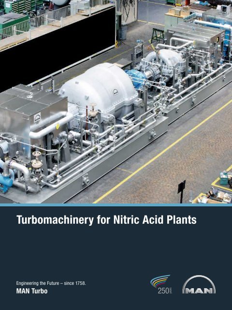
<strong><strong>Turbo</strong>machinery</strong> <strong>for</strong> <strong>Nitric</strong> <strong>Acid</strong> <strong>Plants</strong><br />
Engineering the Future – since 1758.<br />
<strong>MAN</strong> <strong>Turbo</strong>
<strong><strong>Turbo</strong>machinery</strong> <strong>for</strong> nitric acid plants<br />
Nitrid acid, HNO3, is an important intermediate<br />
<strong>for</strong> a variety of products of the<br />
fertilizer and chemical industries. There<br />
are various processes today <strong>for</strong> the production<br />
of nitric acid, which all require<br />
specific mechanical equipment. With the<br />
aid of platinum catalysts, ammonia is<br />
oxidized after which the nitrogen oxides<br />
contained in the combustion gases are<br />
almost completely converted with water<br />
in an absorber to nitric acid. The core<br />
equipment of such nitric acid plants is<br />
the turbomachine train, which in most<br />
cases consists of an air compressor, a<br />
nitrous-gas compressor, a tail-gas turbine<br />
and a steam turbine. There are<br />
many good reasons why this equipment<br />
should come from a competent supplier,<br />
such as <strong>MAN</strong> <strong>Turbo</strong>.<br />
2<br />
Experience<br />
Almost 90 years of turbomachinery<br />
design by <strong>MAN</strong> <strong>Turbo</strong>, including<br />
40 years of experience in manufacturing<br />
machine trains <strong>for</strong> nitric acid plants.<br />
Close cooperation with leading users<br />
and process licensers.<br />
About 460 turbomachines <strong>for</strong> 170<br />
nitric acid plants using the most commonly<br />
applied processes including the<br />
world’s largest plant (2,000 t/day)<br />
Flexibility and versatility<br />
The supply of complex turbomachine<br />
sets should be entrusted to a manufacturer<br />
capable of designing, manufacturing<br />
and testing all of the machines within<br />
the train – compressors and turbines.<br />
<strong>MAN</strong> <strong>Turbo</strong> has the most comprehensive<br />
production and supply programme<br />
in the field of turbomachinery in the<br />
world. This is an asset which guarantees<br />
flexibility and allows the company<br />
to build turbomachines with an optimum<br />
of adaptation to all process requirments.<br />
Another advantage <strong>for</strong> the customer:<br />
the undivided responsibility <strong>for</strong> the whole<br />
machine train lies with <strong>MAN</strong> <strong>Turbo</strong>.<br />
Quality and economy<br />
The high technical standard and the<br />
economy of operation of <strong>MAN</strong> <strong>Turbo</strong><br />
turbomachines are the results not only<br />
of extensive research and development<br />
activities, modern CAD, calculation and<br />
manufacturing techniques, but also of<br />
the availability of high-speed balancing<br />
and overspeed testing equipment as<br />
well as mechanical and thermodynamic<br />
testing facilities. Dismantling <strong>for</strong> shipment?<br />
At <strong>MAN</strong> <strong>Turbo</strong>'s own port – on<br />
the Rhine-Herne-canal close to the port<br />
of Duisburg, the world’s largest river<br />
port – a crane with a handling capacity<br />
of 450 t is available. This allows loading<br />
of complete machine trains, including<br />
their base frames, so that the time needed<br />
<strong>for</strong> erection work on site is significantly<br />
reduced. Result: considerable cost and<br />
time savings during erection on site.
Processes<br />
For the production of nitric acid there<br />
are four basic processes which are distinguished<br />
by their pressure levels <strong>for</strong><br />
combustion and absorption:<br />
4<br />
Low/medium and medium/high<br />
two-pressure process<br />
6<br />
1 Air compressor<br />
2 NH 3 burner<br />
3 NO compressor<br />
1<br />
4 Absorption tower<br />
5 Tail gas expander<br />
6 Steam turbine<br />
2<br />
1. Low/medium two-pressure process<br />
Combustion at atmospheric pressure,<br />
absorption at medium pressure (4-6 bar)<br />
2. Medium-pressure process<br />
Combustion and absorption at medium<br />
pressure (4-6 bar)<br />
3. Medium/high two-pressure process<br />
Combustion at medium pressure (4-6 bar),<br />
absorption at high pressure (10-12 bar)<br />
3<br />
5<br />
4<br />
4. High-pressure process<br />
Combustion and absorption at high<br />
pressure (8-13 bar)<br />
<strong>MAN</strong> <strong>Turbo</strong> has supplied machines <strong>for</strong><br />
all four processes. These are, depending<br />
on the process:<br />
air compressors (cooled and uncooled)<br />
nitrous gas compressors<br />
tail gas expanders<br />
steam turbines.
medium/high-pressure process<br />
5 1<br />
4<br />
1 Air compressor<br />
2 NH 3 burner<br />
3 Absorption tower<br />
4 Tail gas expander<br />
5 Steam turbine<br />
This means, apart from clearly defined<br />
responsibilities, that the necessary<br />
coordinations are much simpler and<br />
the contract handling procedure runs<br />
more smoothly.<br />
Integration of the machines into the<br />
process is graphically shown using the<br />
medium/high two-pressure process and<br />
the high-pressure process as examples.<br />
In the past 15 years the two-pressure<br />
process has gained general acceptance<br />
in Europe <strong>for</strong> nitric acid plants with<br />
capacities of 500 t/day and above.<br />
Smaller plants – mainly outside Europe<br />
use the high-pressure process and the<br />
medium-pressure process.<br />
2<br />
3<br />
The air compressor <strong>for</strong> the two-pressure<br />
process and the medium-pressure process<br />
is an uncooled axial compressor in<br />
most cases, while <strong>for</strong> the high-pressure<br />
process an intercooled centrifugal compressor<br />
is used.<br />
Whilst steam turbines are used as driver<br />
almost exclusively <strong>for</strong> large machine<br />
trains <strong>for</strong> smaller machine sets electric<br />
motors are in service.<br />
5
Axial compressor <strong>for</strong> air<br />
The first axial compressor <strong>for</strong> a nitric<br />
acid plant was built by <strong>MAN</strong> <strong>Turbo</strong> as<br />
early as 1963. For this application the<br />
company developed the type AG, which<br />
has 10-15 axial stages followed by a<br />
centrifugal final stage. <strong>MAN</strong> <strong>Turbo</strong> axial<br />
compressors are built from standardized<br />
stage groups with different degrees of<br />
reaction – from 70 to 85 % in the first<br />
stages and to 100 % in the final stages.<br />
The centrifugal stage replaces two to<br />
6<br />
three axial stages and the outlet diffuser;<br />
it also contributes to improved efficiency<br />
and an extended operating range of the<br />
compressor. <strong>MAN</strong> <strong>Turbo</strong> axial compressors<br />
offer the following advantages:<br />
High efficiency<br />
By the selection of a reduced degree of<br />
reaction in the first stages, flow velocities<br />
can be kept low <strong>for</strong> high flow rates. Installation<br />
of 100 % reaction blading in<br />
the final stages results in optimal channel<br />
sections and relatively small clearances<br />
due to larger blade lengths.<br />
Wide operating characteristics<br />
<strong>MAN</strong> <strong>Turbo</strong> axial compressors with<br />
speed control (e.g., when provided with<br />
steam turbine drive) allow operation<br />
down to a surge point of less than 65 %.<br />
For constant-speed operation it is only<br />
necessary to fit about a third of the
Axial air compressor <strong>for</strong> a 1,230-t/day two pressure plant P = 15,435 kW n = 5,152 rpm<br />
stator blades with variable geometry in<br />
order to obtain the same operating<br />
range as with speed control. About two<br />
thirds of the stator blade rows, in the<br />
MP- and HP- sections, are stationary.<br />
Low susceptibility to fouling and<br />
erosion<br />
The <strong>MAN</strong> <strong>Turbo</strong> axial compressor is<br />
very tolerant of dirty gases. If there is<br />
any accumulation of dirt in the machine<br />
at all, this occurs in the fixed stator<br />
blades, with fouling decreasing from<br />
stage to stage in the direction of flow.<br />
As the <strong>MAN</strong> <strong>Turbo</strong> axial compressor<br />
develops most of the pressure in the<br />
rotor blading, the head generated is not<br />
affected when handling dirty gases;<br />
there will be no change in efficiency<br />
even after long periods of operation.<br />
Gas-borne particles do not present the<br />
<strong>MAN</strong> <strong>Turbo</strong> axial compressor with a<br />
significant erosion hazard as the design<br />
of blading used produces a very low<br />
whirl component, allowing dust to follow<br />
the gas paths without being centrifuged<br />
to high impact velocities. For application<br />
in nitric acid plants, the labyrinths at the<br />
shaft outlets of the bearing housings are<br />
provided with an intermediate air-sealed<br />
chamber to prevent entry of NO-gases<br />
into the oil system.<br />
7
Centrifugal compressor <strong>for</strong> air<br />
For smaller plants using the mediumpressure<br />
process with pressures of<br />
about 6 bar, as weil as <strong>for</strong> highpressure<br />
plants operating in the range between 7<br />
and 15 bar, economically the best solution<br />
today is to use an integrally geared<br />
compressor. Theses multi-shaft compressors<br />
have the advantage over<br />
single-shaft machines, that they allow<br />
direct drive and the integration of a tail<br />
gas expander.<br />
8<br />
These compressors of the type “RG”<br />
are built by <strong>MAN</strong> <strong>Turbo</strong> with a maximum<br />
number of six stages.<br />
By varying the number of intercoolers,<br />
the gas can be delivered at the temperature<br />
required by a particular process.<br />
For the medium-pressure range an uncooled<br />
version is also available.<br />
The advantage of this type of compressor<br />
is that it can be driven either by an<br />
electric motor or by a turbine or by both<br />
at the same time.<br />
For motor driven units, the bull gear is<br />
driven directly. Whereas <strong>for</strong> the turbinedrive<br />
version <strong>MAN</strong> <strong>Turbo</strong> has developed<br />
a design with an additional pinion shaft,<br />
whose transmission ratio is chosen to<br />
allow the compressor to be driven either<br />
by the tail gas expander or the steam<br />
turbine at its optimum speed. The <strong>MAN</strong><br />
<strong>Turbo</strong> integrally geared compressor<br />
offers the following advantages:<br />
high efficiency due to optimum impeller<br />
design, optimum speed selection,<br />
and interstage cooling<br />
low operating costs due to high efficiency<br />
and minimum maintenance<br />
oil-free compression<br />
excellent part-load per<strong>for</strong>mance<br />
high availability<br />
simple operation due to fully automatic<br />
control and monitoring<br />
rugged, compact design.
Integrally geared compressor <strong>for</strong> a high pressure plant<br />
9
Nitrous gas compressor<br />
For the two-pressure process the<br />
nitrous gas compressor is generally of<br />
the centrifugal type. Where the oxidation<br />
pressures are very low, an axial<br />
compressor can be used similar to<br />
low-pressure plants. For nitrous gas<br />
compressors today impellers of high<br />
flowhandling capacity and, if necessary,<br />
with large exit angles (900 impellers) are<br />
also chosen.<br />
10<br />
In designing compressors <strong>for</strong> nitrous<br />
gas, one must take into account that<br />
this gas<br />
<strong>for</strong>ms ammonium nitrite,<br />
nitrate and HNO3 is poisonous,<br />
is highly corrosive,<br />
allows chemical reactions to take<br />
place during compression.<br />
There<strong>for</strong>e, specific design steps have to<br />
be taken and special equipment has to<br />
be installed on the compressor.<br />
The <strong>for</strong>mation of ammonium nitrate deposits,<br />
which under certain circumstances<br />
has an explosive effect, is prevented by<br />
avoiding any dead spaces within the<br />
compressor.<br />
Deposits that may <strong>for</strong>m in the flow<br />
channel are removed by “washing” in<br />
regular intervals.<br />
This is done by spraying steam condensate<br />
into the compressor suction<br />
nozzle. The so-called washing process<br />
is per<strong>for</strong>med during the start-up procedure.<br />
In addition, condensate may be<br />
injected into the machine during normal<br />
operation <strong>for</strong> about five minutes every<br />
eight hours.<br />
Special nozzles spray the water at<br />
high pressure against the gas stream to<br />
give a uni<strong>for</strong>m and precise distribution<br />
guaranteeing quick evaporation of the<br />
water.
This procedure ensures optimum,<br />
gentle cleaning of the flow channel and<br />
has little influence on the process mass<br />
flow rate as only small quantities of<br />
water are injected.<br />
The poisonous effect of nitrous gas<br />
makes it necessary to prevent any escape<br />
of gas from the compressor. This<br />
requirement is met as folIows:<br />
Double sealing chambers are provided<br />
at the main shaft in the casing.<br />
The inboard chambers are fed with<br />
sealing air (from the discharge of<br />
the air compressor), while the outboard<br />
chambers are provided with a<br />
connection to atmosphere. This is led<br />
outside the machine house in case<br />
any leakage does arise. The ingress<br />
of NO-gas into the lube-oil circuit is<br />
prevented by an additional sealing<br />
chamber in each bearing housing<br />
of the machine train.<br />
A special sealing agent is applied<br />
at the horizontal joint flanges of the<br />
casing. In addition, the casing joint<br />
bolts are tightened at an exactly<br />
defined <strong>for</strong>ce by means of a hydraulic<br />
tightening device.<br />
All parts in contact with the gas are<br />
made of acid resistant CrNi steel to<br />
counteract the corrosive effect of the<br />
nitrous gases. The chemical reactions<br />
that occur during compression have to<br />
be taken into account when designing<br />
such a compressor. These reactions<br />
are the dissociation of N2O4 to NO2 and<br />
to a much lesser degree and the<br />
oxidation of NO to NO2. The latter<br />
reaction causes heat to be released,<br />
whereas <strong>for</strong> dissociation considerable<br />
amounts of heat are needed. In<br />
designing the compressor, these heat<br />
quantities/temperature changes are<br />
determined stage by stage and considered<br />
when sizing the flow channel<br />
sections.<br />
Nitrous-gas compressor<br />
11
Tail gas expander<br />
Utilization of the energy still contained in<br />
the tail gas after the absorption process<br />
allows 35 - 100 % of the compressor<br />
drive power to be recovered.<br />
<strong>MAN</strong> <strong>Turbo</strong> builds tailgas expanders <strong>for</strong><br />
a wide range of conditions, both impulse<br />
and reaction turbines, of singlestage<br />
and multi-stage design. For con-<br />
12<br />
trol purposes a system of adjustable<br />
inlet guide vanes has been developed<br />
over the past few years which gives<br />
some advantages over the more traditional<br />
nozzle group control arrangement.<br />
This allows stepless control over the full<br />
operating range and improved efficiency<br />
through the use of a purely reactiontype<br />
blading.<br />
All components in contact with the gas<br />
are made of acid-resistant CrNi steel<br />
to avoid corrosion. The outboard labyrinths<br />
of these machines are also provided<br />
with two intermediate chambers<br />
and are purged with sealing air from the<br />
same source as the seals of the nitrousgas<br />
compressor.
The rotor blades are provided, where<br />
possible, with integral shrouds to give<br />
better sealing between the blades and<br />
the stator. This design also increases<br />
damping to prevent blade vibration<br />
and allows the efficiency to be improved.<br />
The stator blades are fitted in a blade<br />
carrier which is fixed in the turbine<br />
casing in a thermally flexible connection.<br />
The adjustable stator blades can be<br />
brought into the desired position<br />
by means of an electric motor or a<br />
hydraulic actuator.<br />
13
Steam turbine <strong>for</strong> a 1,230-t/day two pressure plant P = 9,410 kW n = 7,973 rpm<br />
Steam turbine<br />
The steam turbine is normally fed with<br />
steam generated in the process. In a<br />
few cases this process steam is utilized<br />
<strong>for</strong> other purposes and the steam turbine<br />
is replaced by an electric motor.<br />
In nitric acid plants the steam turbine<br />
not only has to provide the normal driving<br />
power but also the startup power of<br />
the HNO3 turboset as initially the tail gas<br />
expander does not deliver any power.<br />
14<br />
The start-up power may be more than<br />
twice the normal power.<br />
There is also an increasing demand <strong>for</strong><br />
turbine designs which allow extraction<br />
of a certain steam quantity <strong>for</strong> process<br />
purposes or <strong>for</strong> an additional generator<br />
drive.<br />
For these applications <strong>MAN</strong> <strong>Turbo</strong> provides<br />
condensing steam turbines of<br />
the reaction type with and without extraction<br />
or steam admission.
Steam turbine<br />
The <strong>MAN</strong> <strong>Turbo</strong> modular system<br />
For the important subassemblies of<br />
<strong>MAN</strong> <strong>Turbo</strong> steam turbines, such as<br />
bearing housings, control-valve/nozzle<br />
casing, control-stage casing and exhaust<br />
casing, as well as <strong>for</strong> the connecting<br />
elements, a modular system of<br />
geometrically graded component sizes<br />
has been developed. Combining the<br />
various modules permits flexible adaptation<br />
of the machine to multifarious appli-<br />
cations through the selection of optimum<br />
design features. In order to keep<br />
the blading free from vibration resonance<br />
throughout the speed range, a thick<br />
dropshaped profile with an integral<br />
shroud segment was developed <strong>for</strong> the<br />
rotor blades in the reaction part of the<br />
turbine. This is a very rugged profile;<br />
which can be used within a wide stagger<br />
angle and blade spacing range and is<br />
available with different chord lengths.<br />
The blade selection procedures ensure<br />
resonance free operations. The tapered<br />
twisted rotor blades of the exhaust<br />
stages and the corresponding tapered<br />
stator blades are again selected from a<br />
standard blade range. The rotors are<br />
<strong>for</strong>ged from the solid and are balanced<br />
fully bladed under vacuum conditions at<br />
operating speed.<br />
15
Control and safety equipment<br />
A complex machine train of the kind<br />
used in a nitric acid plant makes very<br />
great demands on the control and protection<br />
systems in terms of quality and<br />
flexibility. Such systems must consider<br />
the requirements of the process and<br />
provide all functions from start-up to<br />
emergency shutdown of the machine<br />
train and process. <strong>MAN</strong> <strong>Turbo</strong> has developed<br />
electronic control and protection<br />
systems which interface with<br />
the mechanically/hydraulically actuated<br />
final control elements.<br />
Anti-surge control, surge detector<br />
In the per<strong>for</strong>mance graph of a turbo<br />
compressor the surge line is the dividing<br />
line between ranges of stable and<br />
un-stable operation. Reduction of the<br />
volume flow rate beyond this line causes<br />
separation of the flow from the<br />
blading, the gas flows periodically from<br />
the discharge end to the suction end –<br />
a phenomenon referred to as compressor<br />
surging. The resultant extreme<br />
load reversals and temperature fluctuations<br />
in the gas-handling components of<br />
the machine must be avoided. This is a<br />
task of the anti-surge control, a system<br />
which, by controlled opening of the<br />
blow-off or by-pass valves, always<br />
keeps the compressor flow rate in the<br />
stable range of the per<strong>for</strong>mance graph.<br />
A special development of <strong>MAN</strong> <strong>Turbo</strong><br />
<strong>for</strong> this purpose is the electronic control<br />
and protection system called “<strong>Turbo</strong>log<br />
S7-400”.<br />
16<br />
Speed control<br />
To allow speed and there<strong>for</strong>e process<br />
pressures and flow rates – to be controlled<br />
as well as the machine train to be<br />
protected against overspeed, <strong>MAN</strong><br />
<strong>Turbo</strong> has developed the turbine control<br />
and protection system “<strong>Turbo</strong>log S7-<br />
400”. This system by far surpasses the<br />
requirements of NEMA specification SM<br />
23, class D. Depending upon specific<br />
requirements, it is designed <strong>for</strong> any of<br />
the following functions: (Refer also to<br />
the special brochure “<strong>Turbo</strong>log S7-<br />
400”.)<br />
redundant turbine speed control<br />
redundant overspeed protection<br />
complete functional testing of all trip<br />
circuits during normal operation<br />
speed-controlled starting of the<br />
turbine from standstill<br />
combined control of speed and<br />
extraction pressures<br />
back-pressure control<br />
control of turbines with sidestream<br />
admission<br />
inlet pressure control<br />
power output control<br />
frequency control
1 Trip valve with steam strainer<br />
2 Live-steam control valves 3 Contral oil<br />
pressure accumulator<br />
4 Speed controller with positioner (<strong>Turbo</strong>log)<br />
5 Sealing-steam control 6 Shaft barring gear<br />
7 By-pass valve<br />
8 Surge detector<br />
9 Non-return flap with closing device<br />
10 Water injection<br />
11 Blow-off valve<br />
12 Anti-surge control 13 Surge detector<br />
14 Non-return flap with closing device<br />
15 Labyrinth sealing air <strong>for</strong> NO-gas compressor<br />
and tail gas expander<br />
16 Labyrinth sealing air <strong>for</strong> bearing pedestals<br />
17 Quick-closing inlet flap 18 Quick-opening<br />
by-pass flap<br />
19 Adjustable stator blades<br />
20 Axial-displacement measurement<br />
21 Bearing-temperature measurement<br />
22 Shaft-vibration measurement<br />
23 Speed monitoring<br />
Quick shutdown<br />
Quick opening of blowoff valve<br />
Control of shaft barring gear<br />
17
Components<br />
Baseframe/steel foundation<br />
If allowed by the local conditions at site,<br />
the entire machine train can be shopmounted<br />
on a common baseframe or<br />
on a steel foundation; this offers the<br />
following great advantages:<br />
all installation and assembly work, including<br />
piping and cabling, can be<br />
done in manufacturer’s works<br />
easy handling during testing and<br />
transport<br />
less time <strong>for</strong> erection<br />
simplification of site work.<br />
18<br />
Oil supply<br />
For the supply of oil to the machine bearings<br />
and the hydraulic control devices,<br />
oil supply units conceived by <strong>MAN</strong><br />
<strong>Turbo</strong> are used. These are designed<br />
either to <strong>MAN</strong> <strong>Turbo</strong> standard or API<br />
Standard 614; customer specifications<br />
can be taken into account if desired.<br />
Gearbox, couplings<br />
A gearbox in the train allows optimum<br />
speeds to be selected <strong>for</strong> the individual<br />
machines within the train. This gearbox<br />
is normally of the single-stage spur-gear<br />
type. The individual casings of the machine<br />
set are connected by gear type or<br />
diaphragm couplings. Also each individual<br />
casing has its own thrust bearing.<br />
This flexible separation has the following<br />
advantages:<br />
minimal effect from adjacent machine<br />
rotors over wide operating conditions<br />
flexibility in selection of machine<br />
arrangement in the train<br />
optimal clearance between stator and<br />
rotor (thereby ensuring best efficiency)<br />
greater inter-casing angular displacement<br />
allowed, e.g., after a long period<br />
of operation.
Quality assurance<br />
<strong>MAN</strong> <strong>Turbo</strong>’s QA programme is the<br />
basis <strong>for</strong> the reliability of the company’s<br />
high-quality products. The QA division,<br />
which reports to the Chairman of the<br />
Executive Board, initiates, coordinates,<br />
and monitors all activities affecting quality,<br />
while also issuing, and controlling<br />
the compliance with, QA Manuals and<br />
Procedures, such as:<br />
Design<br />
Material procurement<br />
Production planning<br />
Fabrication<br />
Functional tests<br />
Procedural qualifications<br />
Calibration of gauges and test<br />
equipment.<br />
The main features of an inspection plan<br />
<strong>for</strong> a nitric acid machine train are:<br />
Destructive testing of specimens<br />
taken from workpieces of the following<br />
components:<br />
- machine casings<br />
- inlet rings<br />
- volutes<br />
- nozzle segments<br />
- stator-blade carriers<br />
- shafts<br />
- impellers<br />
- rotor and stator<br />
- blades<br />
- labyrinth seals<br />
- control-valve/nozzle<br />
- chests<br />
- trip valve internals<br />
Ultrasonic examination after rough<br />
machining and finish-machining of<br />
- cast steel casings<br />
- impellers<br />
- shafts<br />
- rotor and stator blades<br />
- inlet and control-valve/ nozzle<br />
chests<br />
- nozzle segments<br />
Magnetic-particle testing of<br />
- machine casings<br />
- rotor and stator blades<br />
- stator-blade carriers<br />
Due penetrant examination of<br />
- machine casings<br />
- shafts<br />
- impellers<br />
- rotor and stator blades<br />
- stator-blade carriers<br />
Radiography of machine casings<br />
Dimensional and visual examination of<br />
- machine casings (pre-machined and<br />
finish-machined)<br />
- shafts and rotors<br />
Heat stability test of shafts<br />
Hydrostatic testing of casings<br />
Overspeed testing of impellers<br />
Run-out measurement on rotors<br />
Balancing of rotors at operating speed<br />
Clearance measurements on assembled<br />
machines.<br />
19
Workshops<br />
To meet today’s demands <strong>for</strong> high<br />
quality, economic production and short<br />
delivery, advanced workshops qualified<br />
to the latest standards are required.<br />
The new fabrication shops and test<br />
facilities of <strong>MAN</strong> <strong>Turbo</strong>’s turbomachinery<br />
sector satisfy these requirements in<br />
every respect. High-capacity working<br />
facilities have been combined in fabrication<br />
isles <strong>for</strong> an optimum flow of<br />
materials, including equipment <strong>for</strong> the<br />
machining of casings, blade fabrication,<br />
impeller fabrication, rotor machining,<br />
and assembly.<br />
The main machining operations are<br />
per<strong>for</strong>med by CNC machine tools. The<br />
machine tools incorporate the latest<br />
technology.<br />
20
1 Materials receiving<br />
2 Diaphragms<br />
2a Small parts stores<br />
3 Shipment<br />
4 Rotor<br />
4a Materials/toolshop<br />
5 Small parts & blade fabrication<br />
6 Casing fabrication<br />
6a High-bay warehouse<br />
7 Assembly<br />
8 Balancing<br />
9 Stores<br />
10 Gas turbine service shop<br />
11 Large machinery test stand<br />
12 Development test stands<br />
13 Training Shop<br />
14 Screw compressor service shop<br />
15 <strong><strong>Turbo</strong>machinery</strong> service shop<br />
16 Free-field test stand<br />
17 Gas turbine test stand<br />
18 Piping shop<br />
21
Test facility<br />
<strong>MAN</strong> <strong>Turbo</strong> owns and operates different<br />
testbeds <strong>for</strong> turbomachinery in order to<br />
execute factory acceptance tests. One<br />
test centre <strong>for</strong> compressors, steam,<br />
process-gas and industrial-gas turbines<br />
as well as <strong>for</strong> individual components has<br />
been integrated into the production<br />
shops.<br />
Machines/machine trains are completely<br />
assembled in the assembly bay and<br />
subsequently transferred to the adjacent<br />
test stand by two 80 t cranes.<br />
22<br />
After erection on the 44 m long steel<br />
foundation and connection to the permanent<br />
piping systems (steam, air, water,<br />
oil), all kinds of tests to DIN/VDI/ASME/<br />
API can be conducted:<br />
Mechanical testing of the individual<br />
machines<br />
Mechanical testing of a complete<br />
machine train<br />
Thermodynamic testing with air and<br />
other gases in open or closed loop<br />
systems.<br />
The drivers used during testing are<br />
either those supplied under a particular<br />
contract or the various test stand<br />
drivers which are available, i.e.:<br />
An 18 MW condensing steam turbine<br />
One 6.5 MW and two 2.5 MW<br />
variable-speed motors which can,<br />
if necessary, be coupled together.<br />
In 2004 an additional packaging and<br />
test centre <strong>for</strong> large strings was commissioned.<br />
It is now possible to work on up to three<br />
machine trains at the same time, on<br />
an area of over 4400 square meters.<br />
Modules up to 600 tonnes are by no<br />
means an exception.<br />
Two cranes, each capable of lifting<br />
150/180 tonnes, and with a crane hook<br />
height of over 17 metres, guarantee<br />
the necessary flexibilty in the machine<br />
assembly and testing.<br />
This test bed includes a cooling water<br />
circuit with three cooling towers, a 20 MW<br />
electrical power supply in addition to the<br />
steam supply (50 bar, 500 °C, 55 t/h).
Erection and service<br />
All erection and service activities <strong>for</strong><br />
<strong>MAN</strong> <strong>Turbo</strong> machine trains are carried<br />
out by <strong>MAN</strong> <strong>Turbo</strong>’s centralized machinery<br />
service group. The service group’s<br />
activities ensure the greatest possible<br />
availability and operational reliability of<br />
<strong>MAN</strong> <strong>Turbo</strong> turbomachinery even after<br />
many years of operation.<br />
This objective is pursued through<br />
the use of meticulous erection<br />
procedures,<br />
thorough commissioning/trial<br />
operation,<br />
regular inspection,<br />
preventive maintenance,<br />
fast repairs,<br />
readily available spare parts and<br />
extensive advisory services.<br />
The company’s service consultancy<br />
team further ensures expert feedback<br />
on a regular basis to promote the consistent<br />
development of <strong>MAN</strong> <strong>Turbo</strong>’s<br />
products and services. The following<br />
provisions have been made to ensure<br />
comprehensive service to our customers:<br />
a close-knit network of representatives<br />
in many countries of the world<br />
service outlets at strategie points<br />
an independent service workshop at<br />
the company’s Sterkrade works.<br />
Emergency service is available at<br />
Sterkrade<br />
hours.<br />
outside normal working<br />
23
<strong>MAN</strong> <strong>Turbo</strong> AG<br />
Steinbrinkstrasse 1<br />
46145 Oberhausen/Germany<br />
Phone +49. 208. 6 92-01<br />
Fax +49. 208. 6 92-20 19<br />
www.manturbo.com<br />
<strong>MAN</strong> <strong>Turbo</strong> – a member of the <strong>MAN</strong> Group<br />
In the interests of technical progress,<br />
subject to change without notice.<br />
Printed in Germany. December 2008<br />
<strong>Turbo</strong> 1003 e 1208 1.5 ba


