3" Dynabuffer - Dynabrade Inc.
3" Dynabuffer - Dynabrade Inc.
3" Dynabuffer - Dynabrade Inc.

Create successful ePaper yourself
Turn your PDF publications into a flip-book with our unique Google optimized e-Paper software.
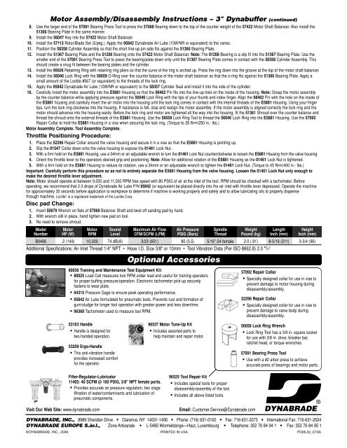
Motor Assembly/Disassembly Instructions – 3" <strong>Dynabuffer</strong> (continued)<br />
8. Use the larger end of the 57091 Bearing Press Tool to press the 57088 Bearing down to the top of the counter weight of the 57422 Motor Shaft Balancer. Also install the<br />
51366 Bearing Plate in the same manner.<br />
9. Install the 56047 Key into the 57422 Motor Shaft Balancer.<br />
10. Install the 57113 Rotor/Blade Set (5/pkg.). Apply the 95842 <strong>Dynabrade</strong> Air Lube (10W/NR or equivalent) to the vanes.<br />
11. Position the 58358 Cylinder Assembly so that the short line-up pin side fits against the 51366 Bearing Plate.<br />
12. Install the 51367 Bearing Plate and the 01206 Bearing onto the 57422 Motor Shaft Balancer. Note: The 01206 Bearing is a slip fit into the 51367 Bearing Plate. Use the<br />
smaller end of the 57091 Bearing Press Tool to press the bearing/plate down only until the 51367 Bearing Plate comes in contact with the 58358 Cylinder Assembly. This<br />
should create a snug fit between the bearing plates and the cylinder.<br />
13. Install the 95626 Retaining Ring with retaining ring pliers so that the curve of the ring is arched up. Press the ring down into the groove at the top of the motor shaft balancer.<br />
14. Install the 56046 Lock Ring with the 50659 O-Ring over the counter balance of the motor shaft balancer so that the o-ring fits against the 51366 Bearing Plate. Apply a<br />
small amount of the Loctite #567 (or equivalent) to the threads of the lock ring.<br />
15. Apply the 95842 <strong>Dynabrade</strong> Air Lube (10W/NR or equivalent) to the 58357 Cylinder Seal and install it into the side of the cylinder.<br />
16. Carefully install the motor assembly into the E5881 Housing so that the 98462 Pin fits into the line-up hole on the inside of the housing. Note: Grasp the motor assembly<br />
by the counter balance while applying pressure against the 56046 Lock Ring with the tips of your thumb and index finger. Align the 98462 Pin with the hole on the inside of<br />
the E5881 housing and carefully insert the air motor into the housing until the lock ring comes in contact with the internal threads of the E5881 Housing. Using your finger<br />
tips, turn the lock ring clockwise into the housing. If resistance is felt, stop and realign the motor assembly. If the motor assembly is aligned correctly the lock ring and the<br />
motor should advance into the housing easily. Before the lock ring and motor are tightened all the way into the housing, fit the 51361 Shroud over the counter balance and<br />
thread the shroud onto the external threads of the E5881 Housing. Use the 56058 Lock Ring Tool to thread the 56046 Lock Ring into the E5881 Housing. Use the 57092<br />
Repair Collar to hold the E5881 Housing in a vise when securing the lock ring. (Torque to 28 N•m/250 in.- lbs.)<br />
Motor Assembly Complete. Tool Assembly Complete.<br />
Throttle Positioning Procedure:<br />
1. Place the 52296 Repair Collar around the valve housing and secure it in a vise so that the E5881 Housing is pointing up.<br />
2. Slip the 01547 Collar down onto the valve housing to expose the 01461 Lock Nut.<br />
3. With a firm hold on the E5881 Housing, use a 34mm or an adjustable wrench to turn the 01461 Lock Nut counterclockwise to loosen the E5881 Housing from the valve housing.<br />
4. Orient the throttle lever to the operators desired grip and positioning. Note: Allow for additional rotation of the E5881 Housing as the 01461 Lock Nut is tightened.<br />
5. With a firm hold on the E5881 Housing to reduce its rotation, use a 34mm or an adjustable wrench to tighten the 01461 Lock Nut. (Torque to 45 N•m/400 in.- lbs.)<br />
Important: Carefully perform this procedure so as not to entirely separate the E5881 Housing from the valve housing. Loosen the 01461 Lock Nut only enough to<br />
make the desired throttle lever adjustment.<br />
Note: Motor should operate at between 9,000 and 11,000 RPM free speed with 80 PSIG of air at the inlet of the tool. RPM should be checked with a tachometer. Before<br />
operating, we recommend that 2-3 drops of <strong>Dynabrade</strong> Air Lube P/N 95842 (or equivalent be placed directly into the air inlet with throttle lever depressed. Operate the machine<br />
for approximately 30 seconds before application to workpiece to determine if machine is working properly and safely and to allow lubricating oils to properly dispense<br />
through machine. Loctite ® is a registered trademark of the Loctite Corp.<br />
Disc pad Change:<br />
1. Insert 50679 Wrench on flats of 57069 Balancer Shaft and twist off sanding pad by hand.<br />
2. With wrench still in place, hand tighten new pad on tool.<br />
3. No need to remove shroud.<br />
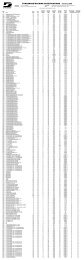
Model Motor Motor Sound Maximum Air Flow Air Pressure Spindle Weight Length Height<br />
Number HP (W) RPM Level CFM/SCFM (LPM) PSIG (Bars) Thread Pound (kg) <strong>Inc</strong>h (mm) <strong>Inc</strong>h (mm)<br />
B0496 .2 (149) 10,000 74 dB(A) 3/23 (651) 80 (5.5) 5/16"-24 female 2.0 (.91) 8-5/16 (211) 3-3/4 (96)<br />
Additional Specifications: Air Inlet Thread 1/4" NPT • Hose I.D. Size 3/8" or 10mm • Tool Vibration Data (Per ISO 8662.8) 2.0 M /S 2<br />
Optional Accessories<br />
80030 Training and Maintenance Test Equipment Kit:<br />
• 80025 Load Cell measures tool RPM under load and useful for training operators<br />
for proper buffing pressure/operation. Electronic tachometer pick-up securely<br />
fastens to wear plate.<br />
• 94315 Pressure Gage to ensure peak operating performance.<br />
• 95842 Air Lube formulated for pneumatic tools. Prevents rust and formation of<br />
gum/sludge for longer tool operation with greater power and less downtime.<br />
• 96368 Tachometer used to measure tool RPM.<br />
57092 Repair Collar<br />
• Specially designed collar for use in vise to<br />
prevent damage to motor housing during<br />
disassembly/assembly.<br />
52296 Repair Collar<br />
• Specially designed collar for use in vise to<br />
prevent damage to valve body during<br />
disassembly/assembly.<br />
53163 Handle<br />
• Handle is designed for<br />
two-handed operation.<br />
53209 Ergo-Handle<br />
• This anti-vibration handle<br />
provides increased comfort<br />
for the operator.<br />
96537 Motor Tune-Up Kit<br />
• <strong>Inc</strong>ludes assorted parts to<br />
help maintain and repair motor.<br />
56058 Lock Ring Wrench<br />
• Lock Ring Tool has a 3/8 in. square socket<br />
for use with 3/8 in. drive; breaker bar,<br />
ratchet head, or torque wrenches.<br />
57091 Bearing Press Tool<br />
• Use with a #2 arbor press to achieve<br />
accurate press of bearings and motor parts.<br />
Visit Our Web Site: www.dynabrade.com<br />
Filter-Regulator-Lubricator<br />
11405: 40 SCFM @ 100 PSIG, 3/8" NPT female ports.<br />
• Provides accurate air pressure regulation, two stage<br />
filtration of water/contaminants and lubrication of<br />
pneumatic components.<br />
96525 Tool Repair Kit<br />
• <strong>Inc</strong>ludes special tools for proper<br />
disassembly/assembly of the tool.<br />
• <strong>Inc</strong>ludes all above listed tools.<br />
Email: Customer.Service@<strong>Dynabrade</strong>.com<br />
DYNABRADE ®<br />
DYNABRADE, INC., 8989 Sheridan Drive • Clarence, NY 14031-1490 • Phone: (716) 631-0100 • Fax: 716-631-2073 • International Fax: 716-631-2524<br />
DYNABRADE EUROPE S.àr.l., Zone Artisanale • L-5485 Wormeldange—Haut, Luxembourg • Telephone: 352 76 84 94 1 • Fax: 352 76 84 95 1<br />
© DYNABRADE, INC., 2006 PRINTED IN USA PD06.20_07/06