3" Dynabuffer - Dynabrade Inc.
3" Dynabuffer - Dynabrade Inc.
3" Dynabuffer - Dynabrade Inc.

Create successful ePaper yourself
Turn your PDF publications into a flip-book with our unique Google optimized e-Paper software.
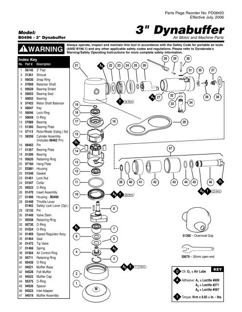
Model:<br />
B0496 - 3" <strong>Dynabuffer</strong><br />
Parts Page Reorder No. PD06•20<br />
Effective July, 2006<br />
3" <strong>Dynabuffer</strong><br />
Air Motor and Machine Parts<br />
Always operate, inspect and maintain this tool in accordance with the Safety Code for portable air tools<br />
(ANSI B186.1) and any other applicable safety codes and regulations. Please refer to <strong>Dynabrade</strong>’s<br />
Warning/Safety Operating Instructions for more complete safety information.<br />
Index Key<br />
No. Part # Description<br />
1 56145 3" Pad<br />
2 51361 Shroud<br />
3 95630 Snap Ring<br />
4 57069 Balancer Shaft<br />
5 95628 Bearing Shield<br />
6 56053 Bearing Seal<br />
7 56052 Bearing<br />
8 57422 Motor Shaft Balancer<br />
9 56047 Key<br />
10 56046 Lock Ring<br />
11 50659 O-Ring<br />
12 57088 Bearing<br />
13 51366 Bearing Plate<br />
14 57113 Rotor/Blade (5/pkg.) Set<br />
15 58358 Cylinder Assembly<br />
(<strong>Inc</strong>ludes 98462 Pin)<br />
16 98462 Pin<br />
17 51367 Bearing Plate<br />
18 01206 Bearing<br />
19 95626 Retaining Ring<br />
20 97166 Hang Plate<br />
21 E5881 Housing<br />
22 01548 Gasket<br />
23 01461 Lock Nut<br />
24 01547 Collar<br />
25 95523 O-Ring<br />
26 01470 Insert Assembly<br />
27 01488 Housing - B0496<br />
28 01448 Throttle Lever<br />
01462 Safety Lock Lever (Opt.)<br />
29 12132 Pin<br />
30 01449 Valve Stem<br />
31 95558 Retaining Ring<br />
32 95730 O-Ring<br />
33 01024 O-Ring<br />
34 01469 Speed Regulator Assy.<br />
35 01464 Seal<br />
36 01472 Tip Valve<br />
37 01468 Spring<br />
38 01564 Air Control Ring<br />
39 95711 Retaining Ring<br />
40 95438 O-Ring<br />
41 94521 Muffler Base<br />
42 94528 Felt Muffler<br />
43 94522 Muffler Cap<br />
44 95375 O-Ring<br />
45 94526 Spacer<br />
46 94523 Inlet Adapter<br />
47 94519 Muffler Assembly<br />
21<br />
14<br />
13<br />
12<br />
11<br />
10<br />
9<br />
A 1<br />
6<br />
4<br />
2<br />
A 8<br />
22 23 24 25 26<br />
A 8 27<br />
T 34 N•m<br />
19<br />
18<br />
17<br />
16<br />
15<br />
O 1<br />
1<br />
A 8<br />
8<br />
7<br />
5<br />
39 40 41 42 43 44 45 46 O 1<br />
A 8 T 23 N•m<br />
T 28 N•m<br />
A 2<br />
3<br />
A 8<br />
T<br />
11.3 N•m<br />
28 29<br />
32<br />
47<br />
33<br />
O<br />
A<br />
T<br />
20<br />
30<br />
31 35<br />
34<br />
51360 – Overmold Grip<br />
50679 – 26mm open-end<br />
Oil: O 1 = Air Lube<br />
36<br />
37<br />
38<br />
KEY<br />
Adhesive: A 1 = Loctite #609<br />
A 2 = Loctite #271<br />
A 8 = Loctite #567<br />
Torque: N•m x 8.85 = In. - lbs.
Important Operating, Maintenance and Safety Instructions<br />
Carefully read all instructions before operating or servicing any <strong>Dynabrade</strong> ® Abrasive Power Tool.<br />
Warning: Hand, wrist and arm injury may result from repetitive work motion and overexposure to vibration.<br />
Important: All <strong>Dynabrade</strong> rotary vane air tools must be used with a Filter-Regulator-Lubricator to maintain all warranties.<br />
Operating Instructions:<br />
Warning: Eye, face, sound, respiratory, and body protection must be worn while operating power tools. Failure to do so may result in serious injury or death. Follow safety<br />
procedures posted in workplace.<br />
Caution: This tool is not to be run at free speed for any length of time. The tool is specifically designed to be low in vibration under load. Running the tool at free speed may<br />
cause the buffing pad to become dislodged from the back-up pad.<br />
1. All initial set-up and maintenance to the tool should be done with the air line disconnected from the tool.<br />
2. Install air fitting into inlet bushing of tool. The inlet bushing is a 1/4" NPT, for optimal performance of the tool, directly couple the air line to the tool or use a quick<br />
couple fitting with a large inlet hole such as <strong>Dynabrade</strong>’s P/N 95675. Important: Secure inlet bushing of tool with a wrench before attempting to install the air fitting to<br />
avoid damaging valve body housing.<br />
3. While there may be other applications suited for this tool it has been specifically designed for the automotive market to be used as the second step of a special two step<br />
operation to remove paint imperfections in the clear coat of automotive finishes. It is imperative that the correct weight mated back-up pad be used with the tool to avoid<br />
excessive vibration. The tool is designed to use a <strong>Dynabrade</strong> P/N 56145 Pad; this pad has a mass of 27 grams.<br />
4. A waffle pad such as 3M P/N 02648 is required to be attached to the back-up pad, other pads may be available contact a <strong>Dynabrade</strong> or 3M representative for additional<br />
information. Pre-condition a virgin pad thoroughly with 3M Final Finish Finesse-It Compound 3M P/N 82876 before attaching it to the tool. Once the pad has been<br />
conditioned this process need not be done until a new waffle pad is required either due to wear or the compound has been allowed to set up rendering the pad useless.<br />
5. Apply a small (15mm) dab of Final Finish on the repaired area, and position tool on the repair surface. Apply approximately a 3 pound load on the pad before throttling<br />
the tool on. Adjust the force on the pad as required to feel the “sweet spot” (low vibration). Buffing for approximately 5 seconds with the pad flat on the work surface<br />
should remove the sand scratches of the initial process. Release the throttle lever and then remove the tool from the work piece.<br />
Maintenance Instructions:<br />
1. Through use of tool the mufflers may clog, hamper performance and require replacement.<br />
2. Check tool speed regularly with a tachometer. A Magnetic Tachometer such as <strong>Dynabrade</strong> P/N 96368 is the simplest way to perform this operation. There are two test<br />
conditions to assure that the tool is running properly, these conditions being free speed and under load. The free speed is a simple check to quickly determine if the tool is<br />
out of specification. Checking under load requires additional test equipment but assures the proper operation of the tool. All speed testing must be done with 80 psig of air<br />
at the inlet bushing, a Pressure Gage such as <strong>Dynabrade</strong> P/N 94315 is required. The tool should run between 9,000 RPM and 11,000 RPM free speed with 80 psig at the<br />
tool inlet bushing. If the tool is running outside these speeds it should be serviced to correct the cause before use. The under load condition can be checked by outfitting<br />
the tool with the proper back-up pad, waffle pad and buffing cream as outlined in the operating instructions. Apparatus is also required to monitor the load applied to the<br />
work surface. <strong>Dynabrade</strong> offers a Load Cell P/N 80025 that allows the tool to be tested on a bench. First zero out the scale by adjusting the knob on the side of the load<br />
cell to read zero when the tool, back-up pad, and waffle are resting on the wear plate of the load cell while connected to the air line. Apply a 3 pound load to the load cell<br />
and using the digital tachometer check the operating speed of the tool. The tool should be running 5,500 RPM minimum. If the tool is running outside this range it should<br />
be serviced to correct the cause before use.<br />
3. All <strong>Dynabrade</strong> rotary vane air motors should be lubricated. <strong>Dynabrade</strong> recommends using <strong>Dynabrade</strong> Air Lube (P/N 95842: 1 pt. 473 ml.) at a rate of 1 drop per minute.<br />
If <strong>Dynabrade</strong> Air Lube is not compatible with paint system it may be substituted with a compatible air tool lubricant with water absorbing properties to prevent internal<br />
components from rusting.<br />
4. It is strongly recommended that all <strong>Dynabrade</strong> rotary vane air tools be used with a Filter-Regulator-Lubricator to minimize the possibility of misuse due to unclean air, wet<br />
air or insufficient lubrication. <strong>Dynabrade</strong> recommends the following: 11405 Air Line Filter-Regulator-Lubricator — Provides accurate air pressure regulation, two-stage<br />
filtration of water contaminants and micro-mist lubrication of pneumatic components. Operates 40 SCFM @ 100 PSIG has 3/8" NPT female ports.<br />
5. Use only genuine <strong>Dynabrade</strong> replacement parts. To reorder replacement parts, please specify the Model #, Serial # and RPM of your machine.<br />
6. A Motor Tune-Up Kit (P/N 96537) is available which includes assorted parts to help maintain motor in peak operating condition.<br />
7. Mineral spirits are recommended when cleaning the tool and parts. Do not clean tool or parts with any solvents or oils containing acids, esters, keytones, chlorinated hydro<br />
carbons or nitro carbons.<br />
Safety Instructions:<br />
Products offered by <strong>Dynabrade</strong> should not be converted or otherwise altered<br />
from original design without expressed written consent from <strong>Dynabrade</strong>, <strong>Inc</strong>.<br />
• Important: User of tool is responsible for following accepted safety codes such as those published by the American National Standards Institute (ANSI).<br />
• Tool should not be running for extended periods of time free speed as it is not balanced for this condition. Avoid running the tool at free speed with a buffing pad installed<br />
onto the back-up pad as it may dislodge from the tool.<br />
• Always disconnect the air line before changing the back-up pad or making machine adjustments.<br />
• Inspect abrasives/accessories for damage or defects prior to installation on tools.<br />
• Please refer to <strong>Dynabrade</strong>’s Warning/Safety Operating Instructions Tag (Reorder No. 95903) for more complete safety information.<br />
• Warning: Hand, wrist and arm injury may result from repetitive work, motion and overexposure to vibration.<br />
Notice<br />
All <strong>Dynabrade</strong> motors use the highest quality parts and metals available and are machined to exacting tolerances. The failure of quality pneumatic motors can most often be<br />
traced to an unclean air supply or the lack of lubrication. Air pressure easily forces dirt or water contained in the air supply into motor bearings causing early failure. It often<br />
scores the cylinder walls and the rotor blades resulting in limited efficiency and power. Our warranty obligation is contingent upon proper use of our tools and cannot apply to<br />
equipment which has been subjected to misuse such as unclean air, wet air or a lack of lubrication during the use of this tool.<br />
One Year Warranty<br />
Following the reasonable assumption that any inherent defect which might prevail in a product will become apparent to the user within one year from the date of purchase, all<br />
equipment of our manufacture is warranted against defects in workmanship and materials under normal use and service. We shall repair or replace at our factory, any<br />
equipment or part thereof which shall, within one year after delivery to the original purchaser, indicate upon our examination to have been defective. Our obligation is contingent<br />
upon proper use of <strong>Dynabrade</strong> tools in accordance with factory recommendations, instructions and safety practices. It shall not apply to equipment which has been subject to<br />
misuse, negligence, accident or tampering in any way so as to affect its normal performance. Normally wearable parts such as bearings, contact wheels, rotor blades, etc., are<br />
not covered under this warranty.<br />
2
Motor Assembly/Disassembly Instructions – 3" <strong>Dynabuffer</strong><br />
Important: Manufacturer’s warranty is void if tool is disassembled before warranty expires.<br />
Notice: All of the special repair tools referred to in these instructions can be ordered from <strong>Dynabrade</strong>. The 96525 Tool Repair Kit is available and the items<br />
contained in this kit are shown on the back of this parts page. Please refer to this parts page for proper part identification.<br />
Motor Disassembly:<br />
1. Disconnect the tool from the air supply.<br />
2. Invert the tool and place the 57092 Repair Collar around the E5881 Housing and the 51361 Shroud, above the two handle<br />
bosses so that the back-up pad is facing up.<br />
3. Use the 50679 Wrench (26mm) to remove the back-up pad.<br />
4. Insert the 56058 Lock Ring Wrench into the tabs of the 56046 Lock Ring and loosen the lock ring from the E5881 Housing by<br />
turning it counterclockwise.<br />
5. Remove the 51361 Shroud from the E5881 Housing by turning it counterclockwise.<br />
6. Pull the motor assembly out of the E5881 Housing and remove the 58357 Cylinder Seal.<br />
7. Use retaining ring pliers to remove the 95626 Retaining Ring.<br />
8. Fasten the 96346 Bearing Separator between the 51367 Bearing Plate and the 58358 Cylinder Assembly.<br />
9. Place the motor assembly with the bearing separator attached, on the table of the 96232 Arbor Press (#2) so that the counter<br />
balance is pointing toward the floor.<br />
10. Use a 3/16" dia. flat end drive punch as a press tool and push the 57422 Motor Shaft Balancer out of the 01206 Bearing.<br />
11. Remove the rotor, vanes, and the 56047 Key from the motor shaft balancer.<br />
12. Remove the 51366 Bearing Plate from the 57088 Bearing.<br />
13. Fasten the bearing separator between the counter balance and the 57088 Bearing and use the arbor press to<br />
remove the bearing.<br />
14. Secure the counter balance portion of the 57422 Motor Shaft Balancer in a vise with aluminum or bronze jaws so that the<br />
26mm hex end of the 57069 Balancer Shaft is accessible and pointing up.<br />
15. Use a small thin screwdriver to pick the notched end of the 95630 Snap Ring out of the motor shaft balancer. Work the<br />
screwdriver under and around the 95630 Snap Ring.<br />
16. Fasten the bearing separator between the 26mm hex end of the 57069 Balancer Shaft and the 95628 Bearing Shield. Place<br />
the separator on the table of the arbor press so that the hex end of the balancer shaft is pointing toward the floor. Use a 5/16"<br />
dia. flat end punch as a press tool and press the 57069 Balancer Shaft out of the 56052 Bearing.<br />
Motor Disassembly Complete.<br />
Valve Disassembly:<br />
1. Place the 52296 Repair Collar around the 01488 Housing and secure it in a vise so that the air inlet is pointing up.<br />
2. Use two wrenches when removing the air fitting. Place one wrench on the 94523 Inlet Adapter to hold it stationary and use<br />
another wrench to remove the air fitting.<br />
3. Remove the inlet adapter from the valve housing. Note: Refer to the exploded view of the muffler assembly to identify the<br />
parts and their order of assembly.<br />
4. Use needle nose pliers to remove the 01468 Spring and the 01472 Tip Valve. The 01464 Seal can be removed from the<br />
valve housing with a small screwdriver.<br />
5. Use retaining ring pliers to remove the 95558 Retaining Ring and push the 01469 Speed Regulator Assembly along with the<br />
01449 Valve Stem out of the valve housing.<br />
6. Use a 2.5mm dia. drive punch to remove the 12132 Pin and the throttle lever.<br />
Valve Disassembly Complete.<br />
Valve Assembly:<br />
Important: Clean and inspect all parts before assembling.<br />
1. Place the 52296 Repair Collar around the 01488 Housing and secure it in a vise so that the air inlet is pointing up.<br />
2. Install the 01469 Speed Regulator Assembly (includes o-rings) into the valve housing and secure it in place with the<br />
95558 Retaining Ring.<br />
3. Insert the 01449 Valve Stem so that the end with the hole fits into the 01469 Speed Regulator Assembly.<br />
4. Install the 01464 Seal into the inlet so that it is laying flat.<br />
5. Use a needle nose pliers to grasp the white nylon portion of the 01472 Tip Valve and insert the metal pin of the tip valve into<br />
the hole of the 01449 Valve Stem.<br />
6. Install the 01468 Spring so that the smaller end of the spring fits against the center of the tip valve.<br />
7. Place the 01564 Air Control Ring against the air inlet opening of the 01488 Housing.<br />
8. Install the 01468 Spring so that the smaller end of the spring fits against the center of the tip valve.<br />
9. Note: Refer to the exploded view of the muffler assembly to identify the parts and their order of assembly. Apply a small<br />
amount of the Loctite #567 (or equivalent) to the threads of the inlet adapter and install it into the air inlet of the valve housing.<br />
(Torque to 23 N•m/200 in.-lbs.)<br />
10. Install the throttle lever and secure it in place with the 12132 Pin.<br />
11. Use two wrenches when installing the air fitting. Place one wrench on the 94523 Inlet Adapter to hold it stationary and use<br />
another wrench to install the air fitting.<br />
Motor Assembly:<br />
1. Place the hex end of the 57069 Balancer Shaft on the table of the 96232 Arbor Press (#2).<br />
2. Install the 95628 Bearing Shield onto the balancer shaft so that the concave side is facing up.<br />
3. Install the 56053 Bearing Seal onto the balancer shaft so that it fits down past the step on the balancer shaft.<br />
4. Apply a small amount of the Loctite #271 (or equivalent) to the bearing surface of the balancer shaft.<br />
5. Position the 56052 Bearing Press Tool to press the bearing down to the step of the 57069 Balancer Shaft.<br />
6. Apply a small amount of Loctite #609 (or equivalent) to the outer diameter of the 56052 Bearing and install the balancer<br />
bearing assembly into the 57422 Motor Shaft Balancer.<br />
7. Important: To avoid injury it is best to hold the counter balance in a vise when the 95630 Snap Ring is being installed. Use a<br />
small thin screwdriver to install the snap ring. Install the 95630 Snap Ring between the hex end of the balancer shaft and the<br />
95628 Bearing Shield. The snap ring must fit into the groove in the motor shaft balancer.<br />
(continued on next page)<br />
Drawing 1<br />
Drawing 2<br />
Drawing 3<br />
Drawing 4<br />
57091<br />
Bearing Press Tool<br />
56052 Bearing<br />
Shaft Step<br />
Bearing Seal and<br />
Bearing Shield<br />
Balancer Shaft<br />
Assembly<br />
57091<br />
Bearing Press Tool<br />
57088 Bearing<br />
Motor Shaft<br />
Balancer<br />
Balancer Shaft<br />
Assembly<br />
57091<br />
Bearing Press Tool<br />
51366<br />
Front Bearing Plate<br />
57088 Bearing<br />
Motor Shaft<br />
Balancer<br />
Balancer Shaft<br />
Assembly<br />
57091Bearing<br />
Press Tool<br />
51367 Rear Bearing<br />
Plate (with 01206<br />
Bearing)<br />
Line-Up Pin<br />
53858 Cylinder<br />
Assembly.<br />
(w/Rotor and Vanes)<br />
51366 Front<br />
Bearing Plate<br />
(with 57088 Bearing)<br />
Motor Shaft<br />
Balancer<br />
Balancer Shaft<br />
Assembly
Motor Assembly/Disassembly Instructions – 3" <strong>Dynabuffer</strong> (continued)<br />
8. Use the larger end of the 57091 Bearing Press Tool to press the 57088 Bearing down to the top of the counter weight of the 57422 Motor Shaft Balancer. Also install the<br />
51366 Bearing Plate in the same manner.<br />
9. Install the 56047 Key into the 57422 Motor Shaft Balancer.<br />
10. Install the 57113 Rotor/Blade Set (5/pkg.). Apply the 95842 <strong>Dynabrade</strong> Air Lube (10W/NR or equivalent) to the vanes.<br />
11. Position the 58358 Cylinder Assembly so that the short line-up pin side fits against the 51366 Bearing Plate.<br />
12. Install the 51367 Bearing Plate and the 01206 Bearing onto the 57422 Motor Shaft Balancer. Note: The 01206 Bearing is a slip fit into the 51367 Bearing Plate. Use the<br />
smaller end of the 57091 Bearing Press Tool to press the bearing/plate down only until the 51367 Bearing Plate comes in contact with the 58358 Cylinder Assembly. This<br />
should create a snug fit between the bearing plates and the cylinder.<br />
13. Install the 95626 Retaining Ring with retaining ring pliers so that the curve of the ring is arched up. Press the ring down into the groove at the top of the motor shaft balancer.<br />
14. Install the 56046 Lock Ring with the 50659 O-Ring over the counter balance of the motor shaft balancer so that the o-ring fits against the 51366 Bearing Plate. Apply a<br />
small amount of the Loctite #567 (or equivalent) to the threads of the lock ring.<br />
15. Apply the 95842 <strong>Dynabrade</strong> Air Lube (10W/NR or equivalent) to the 58357 Cylinder Seal and install it into the side of the cylinder.<br />
16. Carefully install the motor assembly into the E5881 Housing so that the 98462 Pin fits into the line-up hole on the inside of the housing. Note: Grasp the motor assembly<br />
by the counter balance while applying pressure against the 56046 Lock Ring with the tips of your thumb and index finger. Align the 98462 Pin with the hole on the inside of<br />
the E5881 housing and carefully insert the air motor into the housing until the lock ring comes in contact with the internal threads of the E5881 Housing. Using your finger<br />
tips, turn the lock ring clockwise into the housing. If resistance is felt, stop and realign the motor assembly. If the motor assembly is aligned correctly the lock ring and the<br />
motor should advance into the housing easily. Before the lock ring and motor are tightened all the way into the housing, fit the 51361 Shroud over the counter balance and<br />
thread the shroud onto the external threads of the E5881 Housing. Use the 56058 Lock Ring Tool to thread the 56046 Lock Ring into the E5881 Housing. Use the 57092<br />
Repair Collar to hold the E5881 Housing in a vise when securing the lock ring. (Torque to 28 N•m/250 in.- lbs.)<br />
Motor Assembly Complete. Tool Assembly Complete.<br />
Throttle Positioning Procedure:<br />
1. Place the 52296 Repair Collar around the valve housing and secure it in a vise so that the E5881 Housing is pointing up.<br />
2. Slip the 01547 Collar down onto the valve housing to expose the 01461 Lock Nut.<br />
3. With a firm hold on the E5881 Housing, use a 34mm or an adjustable wrench to turn the 01461 Lock Nut counterclockwise to loosen the E5881 Housing from the valve housing.<br />
4. Orient the throttle lever to the operators desired grip and positioning. Note: Allow for additional rotation of the E5881 Housing as the 01461 Lock Nut is tightened.<br />
5. With a firm hold on the E5881 Housing to reduce its rotation, use a 34mm or an adjustable wrench to tighten the 01461 Lock Nut. (Torque to 45 N•m/400 in.- lbs.)<br />
Important: Carefully perform this procedure so as not to entirely separate the E5881 Housing from the valve housing. Loosen the 01461 Lock Nut only enough to<br />
make the desired throttle lever adjustment.<br />
Note: Motor should operate at between 9,000 and 11,000 RPM free speed with 80 PSIG of air at the inlet of the tool. RPM should be checked with a tachometer. Before<br />
operating, we recommend that 2-3 drops of <strong>Dynabrade</strong> Air Lube P/N 95842 (or equivalent be placed directly into the air inlet with throttle lever depressed. Operate the machine<br />
for approximately 30 seconds before application to workpiece to determine if machine is working properly and safely and to allow lubricating oils to properly dispense<br />
through machine. Loctite ® is a registered trademark of the Loctite Corp.<br />
Disc pad Change:<br />
1. Insert 50679 Wrench on flats of 57069 Balancer Shaft and twist off sanding pad by hand.<br />
2. With wrench still in place, hand tighten new pad on tool.<br />
3. No need to remove shroud.<br />
Model Motor Motor Sound Maximum Air Flow Air Pressure Spindle Weight Length Height<br />
Number HP (W) RPM Level CFM/SCFM (LPM) PSIG (Bars) Thread Pound (kg) <strong>Inc</strong>h (mm) <strong>Inc</strong>h (mm)<br />
B0496 .2 (149) 10,000 74 dB(A) 3/23 (651) 80 (5.5) 5/16"-24 female 2.0 (.91) 8-5/16 (211) 3-3/4 (96)<br />
Additional Specifications: Air Inlet Thread 1/4" NPT • Hose I.D. Size 3/8" or 10mm • Tool Vibration Data (Per ISO 8662.8) 2.0 M /S 2<br />
Optional Accessories<br />
80030 Training and Maintenance Test Equipment Kit:<br />
• 80025 Load Cell measures tool RPM under load and useful for training operators<br />
for proper buffing pressure/operation. Electronic tachometer pick-up securely<br />
fastens to wear plate.<br />
• 94315 Pressure Gage to ensure peak operating performance.<br />
• 95842 Air Lube formulated for pneumatic tools. Prevents rust and formation of<br />
gum/sludge for longer tool operation with greater power and less downtime.<br />
• 96368 Tachometer used to measure tool RPM.<br />
57092 Repair Collar<br />
• Specially designed collar for use in vise to<br />
prevent damage to motor housing during<br />
disassembly/assembly.<br />
52296 Repair Collar<br />
• Specially designed collar for use in vise to<br />
prevent damage to valve body during<br />
disassembly/assembly.<br />
53163 Handle<br />
• Handle is designed for<br />
two-handed operation.<br />
53209 Ergo-Handle<br />
• This anti-vibration handle<br />
provides increased comfort<br />
for the operator.<br />
96537 Motor Tune-Up Kit<br />
• <strong>Inc</strong>ludes assorted parts to<br />
help maintain and repair motor.<br />
56058 Lock Ring Wrench<br />
• Lock Ring Tool has a 3/8 in. square socket<br />
for use with 3/8 in. drive; breaker bar,<br />
ratchet head, or torque wrenches.<br />
57091 Bearing Press Tool<br />
• Use with a #2 arbor press to achieve<br />
accurate press of bearings and motor parts.<br />
Visit Our Web Site: www.dynabrade.com<br />
Filter-Regulator-Lubricator<br />
11405: 40 SCFM @ 100 PSIG, 3/8" NPT female ports.<br />
• Provides accurate air pressure regulation, two stage<br />
filtration of water/contaminants and lubrication of<br />
pneumatic components.<br />
96525 Tool Repair Kit<br />
• <strong>Inc</strong>ludes special tools for proper<br />
disassembly/assembly of the tool.<br />
• <strong>Inc</strong>ludes all above listed tools.<br />
Email: Customer.Service@<strong>Dynabrade</strong>.com<br />
DYNABRADE ®<br />
DYNABRADE, INC., 8989 Sheridan Drive • Clarence, NY 14031-1490 • Phone: (716) 631-0100 • Fax: 716-631-2073 • International Fax: 716-631-2524<br />
DYNABRADE EUROPE S.àr.l., Zone Artisanale • L-5485 Wormeldange—Haut, Luxembourg • Telephone: 352 76 84 94 1 • Fax: 352 76 84 95 1<br />
© DYNABRADE, INC., 2006 PRINTED IN USA PD06.20_07/06