CAN J1939 High Amp Relay Module GS10324010 - GSNA.com
CAN J1939 High Amp Relay Module GS10324010 - GSNA.com
CAN J1939 High Amp Relay Module GS10324010 - GSNA.com

You also want an ePaper? Increase the reach of your titles
YUMPU automatically turns print PDFs into web optimized ePapers that Google loves.
OVERVIEW<br />
XHA3 HI AMP RELAY MODULE: <strong>CAN</strong> CONTROLLED<br />
The <strong>High</strong> Current I/O <strong>Module</strong> is a printed<br />
circuit board relay controller with <strong>J1939</strong> <strong>CAN</strong><br />
bus <strong>com</strong>munication.<br />
The module is designed to be<br />
controlled by a GS switch panel or as a node<br />
on a <strong>J1939</strong> <strong>CAN</strong> bus. It uses advanced<br />
<strong>com</strong>munication technology in <strong>com</strong>bination<br />
with traditional mechanical relays which<br />
provides the operator or mechanic better<br />
diagnostic and troubleshooting features.<br />
When determining assembly, this unit<br />
has the ability to “stand alone” or be<br />
controlled by a <strong>J1939</strong> relay module. In addition,<br />
it can be mounted in a standard enclosure or<br />
customized to fit your needs.<br />
Housing<br />
6.0” x 9.5” x 1.8”<br />
Diagnostics<br />
Status LED for operation and troubleshooting<br />
Supply<br />
12 Volt (9-18Vdc) or 24 Volt (+17Vdc +32Vdc)<br />
Outputs<br />
8 <strong>Relay</strong>s from 5 to 20 <strong>Amp</strong> outputs individually<br />
protected<br />
2 <strong>Relay</strong>s at 30 <strong>Amp</strong> outputs individually protected<br />
Eight (8) FET Outputs 3 <strong>Amp</strong>s Continuous<br />
Outputs are rated to connector terminal<br />
limitation<br />
All outputs are protected via the fuse/circuit<br />
breaker<br />
Each relay is circuit protected either fuse or circuit<br />
breaker.<br />
20 <strong>Amp</strong>s maximum; continuous outputs at 80ºC<br />
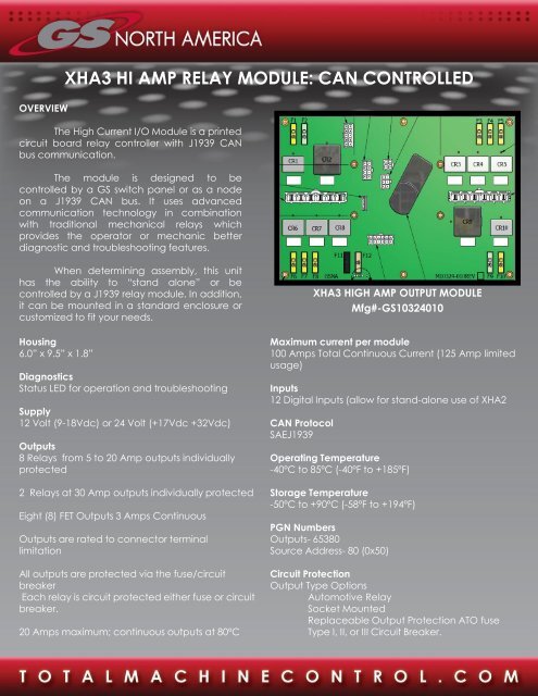
XHA3 HIGH AMP OUTPUT MODULE<br />
Mfg#-<strong>GS10324010</strong><br />
Maximum current per module<br />
100 <strong>Amp</strong>s Total Continuous Current (125 <strong>Amp</strong> limited<br />
usage)<br />
Inputs<br />
12 Digital Inputs (allow for stand-alone use of XHA2<br />
<strong>CAN</strong> Protocol<br />
SAE<strong>J1939</strong><br />
Operating Temperature<br />
-40ºC to 85ºC (-40ºF to +185ºF)<br />
Storage Temperature<br />
-50ºC to +90ºC (-58ºF to +194ºF)<br />
PGN Numbers<br />
Outputs- 65380<br />
Source Address- 80 (0x50)<br />
Circuit Protection<br />
Output Type Options<br />
Automotive <strong>Relay</strong><br />
Socket Mounted<br />
Replaceable Output Protection ATO fuse<br />
Type I, II, or III Circuit Breaker.
HOUSING<br />
XHA3 HI AMP RELAY MODULE: <strong>CAN</strong> CONTROLLED
XHA3 HI AMP RELAY MODULE: <strong>CAN</strong> CONTROLLED<br />
CONNECTIONS<br />
J1 Connector: Mating Connector: <strong>Amp</strong>henol C10-<br />
647184-061<br />
Pin 1: +Supply (100 <strong>Amp</strong>) (Continuous)<br />
J2 Connector: Machine Connection<br />
Mating Connector: Molex 39-01-2125<br />
Pin 1: +Battery Supply<br />
Pin 2: Power Switch Supply<br />
Pin 3: Power Point (+)<br />
Pin 4: Common Supply<br />
Pin 5: Open<br />
Pin 6: Open<br />
Pin 7: Digital Input 1<br />
Pin 8: Digital Input 2<br />
Pin 9: Digital Input 3<br />
Pin 10: Digital Input 4<br />
Pin 11: Digital Input 5<br />
Pin 12: Digital Input 6<br />
J3 Connector: Can Connection<br />
Mating Connector: Molex 39-01-3042<br />
Pin 1: <strong>CAN</strong>-H<br />
Pin 2: <strong>CAN</strong>-L<br />
Pin 3: <strong>CAN</strong> Shield<br />
Pin 4: No Connection<br />
J4 Connector: <strong>Relay</strong> Outputs 1-5<br />
Mating Connector: Molex 43914-1101 Mini-Fit SR.<br />
Pin 1: <strong>Relay</strong> 1- to 20 <strong>Amp</strong><br />
Pin 2: <strong>Relay</strong> 2- 30 <strong>Amp</strong><br />
Pin 3: <strong>Relay</strong> 3- to 20 <strong>Amp</strong><br />
Pin 4: <strong>Relay</strong> 4- to 20 <strong>Amp</strong><br />
Pin 5: <strong>Relay</strong> 5- to 20 <strong>Amp</strong><br />
Pin 6: No Connection<br />
J5 Connector: <strong>Relay</strong> Outputs 6-10<br />
Mating Connector: Molex 43914-1101 Mini-Fit SR.<br />
Pin 1: <strong>Relay</strong> 6- to 20 <strong>Amp</strong><br />
Pin 2: <strong>Relay</strong> 7 - to 20 <strong>Amp</strong><br />
Pin 3: <strong>Relay</strong> 8- to 20 <strong>Amp</strong><br />
Pin 4: <strong>Relay</strong> 9 – 30 <strong>Amp</strong><br />
Pin 5: <strong>Relay</strong> 10- to 20 <strong>Amp</strong><br />
Pin 6: No Connection<br />
J6 Connector: FET Outputs- 4 <strong>Amp</strong> Control<br />
Mating Connector: Molex 39-01-2100<br />
Pin 1: FET Out 1<br />
Pin 2: FET Out 2<br />
Pin 3: FET Out 3<br />
Pin 4: FET Out 4<br />
Pin 5: FET Out 5<br />
Pin 6: FET Out 6<br />
Pin 7: FET Out 7<br />
Pin 8: FET Out 8<br />
Pin 9: FET Common Supply<br />
Pin 10: FET Common Supply<br />
J7 Connector: FET External Input Control<br />
Mating Connector: Molex 39-01-2080<br />
Pin 1: <strong>Relay</strong> or FET Input 1<br />
Pin 2: <strong>Relay</strong> or FET Input 2<br />
Pin 3: <strong>Relay</strong> or FET Input 3<br />
Pin 4: <strong>Relay</strong> or FET Input 4<br />
Pin 5: <strong>Relay</strong> or FET Input 5<br />
Pin 6: <strong>Relay</strong> or FET Input 6<br />
Pin 7: <strong>Relay</strong> or FET Input 7<br />
Pin 8: <strong>Relay</strong> or FET Input 8<br />
J8 Connector: Switch panel Control RS-485<br />
Mating Connector: Molex 39-01-2060<br />
Pin 1: Switch Panel RS-485-A<br />
Pin 2: Switch Panel Common Supply<br />
Pin 3: Switch Panel +5VDC Supply<br />
Pin 4: Switch Panel RS-485-/B<br />
Pin 5: No Connection<br />
Pin 6: Switch Panel Shield<br />
!!!!!!!!!!!!WARNING!!!!!!!!!!!!<br />
FAILURE OR IMPROPER SELECTION OR IMPROPER USE OF THE PRODUCT AND/OR SYSTEMS DESCRIBED HEREIN OR RELATED<br />
ITEMS <strong>CAN</strong> CAUSE DEATH, PERSONAL INJURY AND PROPERTY DAMAGE<br />
This document and other information from GS North America LLC its subsidiaries and authorized distributors provide product and/or<br />
system options for further investigations by users having technical expertise. It is important that you analyze all aspects of your<br />
application, including consequences of any failure, and review the information concerning the products or systems, the user, through<br />
its own analysis and testing, is solely responsible for making the final selection of the products and systems and assuring that all<br />
performance, safety and warning requirements of the application are met. The products described herein, including without<br />
limitation, product features, specifications, designs, availability and pricing, are subject to change by GS North America LLC and its<br />
subsidiaries at any time without notice
<strong>CAN</strong> Create flexibility And Control<br />
GS North America integrates <strong>CAN</strong> control solutions for OEMs operating in some of the harshest<br />
environments around the globe. <strong>GSNA</strong> turns your ideas into reality creating<br />
innovative and cost-effective control solutions.<br />
Our Customers Can Expect<br />
•Unparalleled technical ability in the mobile electronic and hydraulic systems integration<br />
•Specialized in <strong>J1939</strong> <strong>CAN</strong> solutions for the mobile machinery market<br />
•Standardized <strong>com</strong>ponents utilized in custom solutions to meet all manufacturer’s needs