Failure Analysis of Short Faults on Advanced Wire ... - DfR Solutions
Failure Analysis of Short Faults on Advanced Wire ... - DfR Solutions
Failure Analysis of Short Faults on Advanced Wire ... - DfR Solutions

You also want an ePaper? Increase the reach of your titles
YUMPU automatically turns print PDFs into web optimized ePapers that Google loves.
<str<strong>on</strong>g>Failure</str<strong>on</strong>g> <str<strong>on</strong>g>Analysis</str<strong>on</strong>g> <str<strong>on</strong>g>of</str<strong>on</strong>g> <str<strong>on</strong>g>Short</str<strong>on</strong>g> <str<strong>on</strong>g>Faults</str<strong>on</strong>g> <strong>on</strong> <strong>Advanced</strong> <strong>Wire</strong>-b<strong>on</strong>d and<br />
Flip-chip Packages with Scanning SQUID Microscopy<br />
Steve K. Hsiung, Kevan V. Tan, Andrew J. Komrowski, Daniel J. D. Sullivan<br />
LSI Logic Corporati<strong>on</strong>, 3098 West Warren Avenue, Frem<strong>on</strong>t, California 94539<br />
Tel: 408-433-8838 Fax: 408-433-8892 Email: stevehs@lsil.com<br />
Jan Gaudestad<br />
Neocera, Inc., 10000 Virginia Manor Road, Beltsville, Maryland 20705<br />
Tel: 301-210-1010 Fax: 301-210-1042 Email: gaudestad@neocera.com<br />
Abstract<br />
Scanning SQUID (Superc<strong>on</strong>ducting Quantum Interference<br />
Device) Microscopy, known as SSM, is a n<strong>on</strong>-destructive<br />
technique that detects magnetic fields in Integrated Circuits<br />
(IC). The magnetic field, when c<strong>on</strong>verted to current density<br />
via Fast Fourier Transform (FFT), is particularly useful to<br />
detect shorts and high resistance (HR) defects. A short<br />
between two wires or layers will cause the current to<br />
diverge from the path the designer intended. An analyst can<br />
see where the current is not matching the design, thereby<br />
easily localizing the fault. Many defects occur between or<br />
under metal layers that make it impossible using visible<br />
light or infrared emissi<strong>on</strong> detecting equipment to locate the<br />
defect. SSM is the <strong>on</strong>ly tool that can detect signals from<br />
defects under metal layers, since magnetic fields are not<br />
affected by them. New analysis s<str<strong>on</strong>g>of</str<strong>on</strong>g>tware makes it possible<br />
for the analyst to overlay design layouts, such as CAD<br />
Knights, directly <strong>on</strong>to the current paths found by the SSM.<br />
In this paper, we present four case studies where SSM<br />
successfully localized short faults in advanced wire-b<strong>on</strong>d<br />
and flip-chip packages after other fault analysis methods<br />
failed to locate the defects.<br />
Introducti<strong>on</strong><br />
SQUID (Superc<strong>on</strong>ducting Quantum Interference Device) is<br />
the most sensitive magnetic field detector currently known.<br />
In recent years, current imaging through magnetic field<br />
detecti<strong>on</strong> using a SQUID sensor has become a mainstream<br />
approach for short localizati<strong>on</strong> in the package [1]. The<br />
technique is also utilized for die level applicati<strong>on</strong>s [2].<br />
Magnetic fields are not blocked by typical package and<br />
semic<strong>on</strong>ductor materials such as package molding<br />
compounds, heat sinks, metal layers or silic<strong>on</strong>. The device<br />
can therefore be examined n<strong>on</strong>-destructively.<br />
is typically inversely proporti<strong>on</strong>al to the distance between<br />
the sensor and the source [3] .<br />
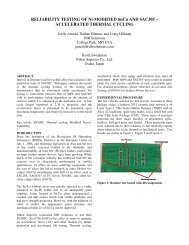
The MAGMA-C20 (Figure 1) is a commercial magnetic<br />
field imaging microscope designed for failure analysis <str<strong>on</strong>g>of</str<strong>on</strong>g><br />
ICs, packages, and boards. It employs a high-temperature<br />
SQUID that is cooled down to 77 K. The microscope keeps<br />
the SQUID cold and in vacuum, while the DUT is at room<br />
temperature in air. The SQUID can be positi<strong>on</strong>ed as close<br />
as 50 mm from the DUT. Resoluti<strong>on</strong> <str<strong>on</strong>g>of</str<strong>on</strong>g> the system is ±3 µm<br />
when the distance from the SQUID to the current carrying<br />
structure is about 250 µm or less. The system has a<br />
sensitivity <str<strong>on</strong>g>of</str<strong>on</strong>g> 20 picotesla, or two milli<strong>on</strong> times smaller than<br />
the Earth’s magnetic field, making it sensitive enough to<br />
detect currents as small as 10 nA at a 100 mm working<br />
distance with 1 sec<strong>on</strong>d averaging.<br />
The SQUID sensor is oriented paralle l to the plane <str<strong>on</strong>g>of</str<strong>on</strong>g> the<br />
sample and is therefore <strong>on</strong>ly sensitive to the Z-comp<strong>on</strong>ent <str<strong>on</strong>g>of</str<strong>on</strong>g><br />
the magnetic field (the comp<strong>on</strong>ent perpendicular to the<br />
scanning plane). The SQUID is held stati<strong>on</strong>ary while the<br />
DUT is raster scanned under the magnetic sensor in a n<strong>on</strong>c<strong>on</strong>tact<br />
mode to acquire the magnetic field image. The<br />
current supplied to the DUT is typically alternating at a<br />
frequency less than 20 kHz. By using a lock-in technique,<br />
an image <str<strong>on</strong>g>of</str<strong>on</strong>g> just the supplied current can be acquired while<br />
static background fields are ignored, enabling the system to<br />
work in an unshielded envir<strong>on</strong>ment. The interpretati<strong>on</strong> <str<strong>on</strong>g>of</str<strong>on</strong>g><br />
the magnetic field image is difficult so a Fast Fourier<br />
Transform (FFT) back-evoluti<strong>on</strong> technique is used to<br />
transform the magnetic field image into an equivalent<br />
current image <str<strong>on</strong>g>of</str<strong>on</strong>g> the integrated circuit or packaged device<br />
[3, 4]. The resulting current map can then be compared to a<br />
circuit diagram or optical/IR image to determine the fault<br />
locati<strong>on</strong>.<br />
The magnetic field strength scales with current magnitude<br />
and decreases with separati<strong>on</strong> between the sensor and<br />
source currents. The rate <str<strong>on</strong>g>of</str<strong>on</strong>g> decrease depends <strong>on</strong> the nature<br />
<str<strong>on</strong>g>of</str<strong>on</strong>g> the current source, but for ICs the magnetic-field strength
Figure 1 Magma -C20 Scanning SQUID Microscope (SSM)<br />
The basic steps <str<strong>on</strong>g>of</str<strong>on</strong>g> SSM analysis used <strong>on</strong> advanced wireb<strong>on</strong>d<br />
and flip -chip packages fall into five categories:<br />
· Sample Preparati<strong>on</strong><br />
· Scanning<br />
· Data <str<strong>on</strong>g>Analysis</str<strong>on</strong>g><br />
· Fault Localizati<strong>on</strong><br />
· Fault Validati<strong>on</strong><br />
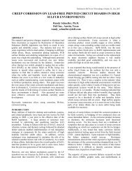
<strong>Advanced</strong> <strong>Wire</strong>-b<strong>on</strong>d Packages<br />
<strong>Advanced</strong> wire-b<strong>on</strong>d packages, unlike traditi<strong>on</strong>al Ball Grid<br />
Array (BGA) packages, have multiple pad rows <strong>on</strong> the die<br />
and multiple tiers <strong>on</strong> the substrate (Figure 2 and Figure 3).<br />
The advanced wire-b<strong>on</strong>d packages at LSI Logic have high<br />
pin count and small die size employing LSI Logic’s Gflx<br />
Cu/Low-K process and Pad-<strong>on</strong>-IO wire b<strong>on</strong>ding.<br />
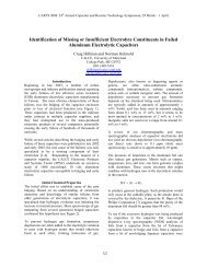
Figure 3 X-ray image <str<strong>on</strong>g>of</str<strong>on</strong>g> a traditi<strong>on</strong>al wire -b<strong>on</strong>d package<br />
This package technology has brought new challenges to<br />
failure analysis. To date, Scanning Acoustic Microscopy<br />
(SAM), Time Domain Reflectometry (TDR) analysis, and<br />
Real-Time X-ray (RTX) inspecti<strong>on</strong> were the n<strong>on</strong>-destructive<br />
tools used to detect short faults. Unfortunately, these<br />
techniques do not work very well in advanced wire-b<strong>on</strong>d<br />
packages: SAM is used to detect anomalies at die and<br />
package interfaces; TDR can <strong>on</strong>ly tell if the short occurs <strong>on</strong><br />
die side or substrate. Most importantly, because <str<strong>on</strong>g>of</str<strong>on</strong>g> the highdensity<br />
wire b<strong>on</strong>ding in advanced wire-b<strong>on</strong>d packages, it is<br />
extremely hard to localize the short with c<strong>on</strong>venti<strong>on</strong>al RTX<br />
inspecti<strong>on</strong>.<br />
Without detailed informati<strong>on</strong> as to where the short might<br />
occur, attempting destructive decapsualti<strong>on</strong> to expose both<br />
die surface and b<strong>on</strong>d wires is full <str<strong>on</strong>g>of</str<strong>on</strong>g> risk. Wet chemical<br />
etching to remove mold compound in a large area <str<strong>on</strong>g>of</str<strong>on</strong>g>ten<br />
results in overetching. Furthermore, even if the package is<br />
successfully decapped, visual inspecti<strong>on</strong> <str<strong>on</strong>g>of</str<strong>on</strong>g> the multi-tiered<br />
b<strong>on</strong>d wires is a blind search.<br />
SSM analysis, however, provides an alternative and new<br />
n<strong>on</strong>-destructive approach to localize short faults.<br />
Figure 2 X-ray image <str<strong>on</strong>g>of</str<strong>on</strong>g> an advanced wire -b<strong>on</strong>d package<br />
Sample Preparati<strong>on</strong><br />
To improve the resoluti<strong>on</strong> <str<strong>on</strong>g>of</str<strong>on</strong>g> the SSM images, cursory<br />
sample preparati<strong>on</strong> is necessary. On wire b<strong>on</strong>d packages,<br />
the mold cap needs to be thinned as much as possible.<br />
Typically it is lapped down to the top <str<strong>on</strong>g>of</str<strong>on</strong>g> the b<strong>on</strong>d wire loop<br />
without c<strong>on</strong>tacting the b<strong>on</strong>d wires. This allows the SQUID<br />
sensor to be rastered closely to the sample surface, while<br />
ensuring the device retains electrical functi<strong>on</strong>ality.<br />
Scanning<br />
<strong>Wire</strong>s are soldered to the solder balls <str<strong>on</strong>g>of</str<strong>on</strong>g> a DUT. The device<br />
is then put <strong>on</strong> the stage in the probe stati<strong>on</strong> <str<strong>on</strong>g>of</str<strong>on</strong>g> SSM. An AC<br />
voltage is applied to the device proporti<strong>on</strong>al to the current <str<strong>on</strong>g>of</str<strong>on</strong>g><br />
the short fault. If the device is packaged with a daisy-chain<br />
die, given the resistance between the shorted pins, the<br />
voltage applied should make the current less than 2 mA.<br />
Each scan takes about forty-five minutes to <strong>on</strong>e hour<br />
depending <strong>on</strong> scanning area and image resoluti<strong>on</strong>.
Data <str<strong>on</strong>g>Analysis</str<strong>on</strong>g><br />
The SSM data are current density images and current peak<br />
images. The current density images give the magnitude <str<strong>on</strong>g>of</str<strong>on</strong>g><br />
the current, while the current peak images reveal the current<br />
path with a ± 3 µm resoluti<strong>on</strong>.<br />
Obtaining the SSM data from scanning advanced wire-b<strong>on</strong>d<br />
packages is <strong>on</strong>ly half the task; fault localizati<strong>on</strong> is still<br />
necessary. The critical step is to overlay the SSM current<br />
images or current path images with CAD files such as<br />
b<strong>on</strong>ding diagrams or RTX images to pinpoint the fault<br />
locati<strong>on</strong>.<br />
To make alignment <str<strong>on</strong>g>of</str<strong>on</strong>g> overlaying possible, an optical twopoint<br />
reference alignment is made. The package edge and<br />
package fiducial are the most c<strong>on</strong>venient package markings<br />
to align to.<br />
Fault Localizati<strong>on</strong><br />
Based <strong>on</strong> the data analysis, fault localizati<strong>on</strong> by SSM should<br />
isolate the short in the die, b<strong>on</strong>d wires or package substrate.<br />
Figure 5 SSM current peak image<br />
Fault Validati<strong>on</strong><br />
After all n<strong>on</strong>-destructive approaches are exhausted, the final<br />
step is destructive deprocessing to verify SSM data.<br />
Depending <strong>on</strong> fault isolati<strong>on</strong>, the deprocessing techniques<br />
include decapsulati<strong>on</strong>, parallel lapping or cross-secti<strong>on</strong>.<br />
Case Study I<br />
One advanced wire -b<strong>on</strong>d package device failed with a short<br />
between two I/O pins. TDR analysis characterized the short<br />
to bey<strong>on</strong>d the bare substrate (i.e. the b<strong>on</strong>d wires), but RTX<br />
inspecti<strong>on</strong> did not show any anomalies.<br />
The device was then analyzed by SSM. The SSM current<br />
density image (Figure 4) and current peak image (Figure 5)<br />
were obtained. The current density image was then overlaid<br />
to the b<strong>on</strong>ding diagram (Figure 6). The short is <strong>on</strong> the die<br />
side (Figure 7).<br />
Figure 6 CAD file <str<strong>on</strong>g>of</str<strong>on</strong>g> the b<strong>on</strong>ding diagram<br />
Figure 7 SSM current density image overlaying CAD file<br />
Figure 4 SSM current density image<br />
The device was then chemically decapped <strong>on</strong> the die<br />
surface. Visual inspecti<strong>on</strong> revealed a partially lifted ball<br />
b<strong>on</strong>d from <strong>on</strong>e failing I/O pin c<strong>on</strong>tacting the b<strong>on</strong>d wire <str<strong>on</strong>g>of</str<strong>on</strong>g>
the other failing I/O pin (Figure 8). The short went away<br />
after the ball b<strong>on</strong>d was pushed away.<br />
Figure 10 SSM current peak image overlaid with b<strong>on</strong>ding<br />
diagram pinpoints short to b<strong>on</strong>d wires close to the power<br />
ring<br />
Figure 8 Optical image <str<strong>on</strong>g>of</str<strong>on</strong>g> the lifted ball b<strong>on</strong>d <str<strong>on</strong>g>of</str<strong>on</strong>g> <strong>on</strong>e failing<br />
I/O pin that was touching the b<strong>on</strong>d wire <str<strong>on</strong>g>of</str<strong>on</strong>g> the other failing<br />
I/O pin<br />
Case Study II<br />
One advanced wire -b<strong>on</strong>d package device failed with a short<br />
between I/O and VSS. TDR analysis showed that the short<br />
was again bey<strong>on</strong>d the bare substrate. Again, RTX<br />
inspecti<strong>on</strong> did not show any anomalies.<br />
The SSM current peak image (Figure 9) overlaid with the<br />
b<strong>on</strong>ding diagram pinpointed the short to b<strong>on</strong>d wires close to<br />
the power ring (Figure 10).<br />
Chemical decapsulati<strong>on</strong> to expose b<strong>on</strong>d wires is risky,<br />
because it <str<strong>on</strong>g>of</str<strong>on</strong>g>ten results in overetching. Employing a laser<br />
ablati<strong>on</strong> tool, the mold compound was selectively removed<br />
at the target area, exposing the entire b<strong>on</strong>d wire loop (Figure<br />
11).<br />
Figure 11 Optical image <str<strong>on</strong>g>of</str<strong>on</strong>g> the device where mold<br />
compound was partially removed by a laser decapsulati<strong>on</strong><br />
tool<br />
Based <strong>on</strong> SSM data, visual inspecti<strong>on</strong> was focused at the<br />
VSS power ring. Two b<strong>on</strong>d wires were observed to be<br />
shorting close to the power ring (Figure 12). The short<br />
disappeared after the two b<strong>on</strong>d wires were separated.<br />
Figure 9 SSM current density/peak image<br />
Figure 12 Optical image <str<strong>on</strong>g>of</str<strong>on</strong>g> two shorted b<strong>on</strong>d wires in the<br />
area indicated by SSM data
Flip-chip Packages<br />
Until recently, localizing power short fault in the core area<br />
<str<strong>on</strong>g>of</str<strong>on</strong>g> LSI Logic’s flip-chip packages with n<strong>on</strong>-destructive<br />
methods was challenging. TDR analysis does not apply for<br />
power shorts. The most comm<strong>on</strong> technique was to separate<br />
the die from the substrate and perform random inspecti<strong>on</strong><br />
through parallel-lap <str<strong>on</strong>g>of</str<strong>on</strong>g> the substrate. Given the large area <str<strong>on</strong>g>of</str<strong>on</strong>g><br />
the power core (Figure 13), most <str<strong>on</strong>g>of</str<strong>on</strong>g> the time searching<br />
without localizati<strong>on</strong> was in vain.<br />
Y<br />
Figure 15 Optical image <str<strong>on</strong>g>of</str<strong>on</strong>g> a die backside after the die is<br />
thinned down to 100mm and the die backside surface is<br />
covered by an anti-reflective coating material<br />
Core Area <str<strong>on</strong>g>of</str<strong>on</strong>g><br />
VDD and VSS<br />
Figure 13 IR image <str<strong>on</strong>g>of</str<strong>on</strong>g> a core area <str<strong>on</strong>g>of</str<strong>on</strong>g> VDD and VSS where<br />
X-Y positi<strong>on</strong> is marked<br />
With SSM analysis it is possible to localize the X-Y<br />
positi<strong>on</strong> <str<strong>on</strong>g>of</str<strong>on</strong>g> short faults in the core. More importantly, Z-<br />
positi<strong>on</strong> informati<strong>on</strong> is available. This makes possible<br />
distinguishing shorts in the interc<strong>on</strong>nect solder bumps from<br />
shorts in the package substrate (Figure 14).<br />
X<br />
Scanning<br />
To protect short defects from fusing open, an AC voltage is<br />
applied to the devices such that the current is less than 2 mA.<br />
Our studies have shown that short faults in the substrate<br />
may blow out if the current is above 2 mA for this defect.<br />
There are four SSM and camera images that can be obtained<br />
from flip-chip packages: current density images, peak<br />
images, optical/Infra Red (IR) images and static magnetic<br />
field images. The procedures to localize short faults in X-<br />
Y-Z positi<strong>on</strong> may include four steps:<br />
Step 1 Power up VDD and VSS pins. Then perform SSM<br />
to see if there is a spot with str<strong>on</strong>g current density.<br />
Step 2 Power up different VDD and VSS pins. Then<br />
perform SSM to see if there are other spots with str<strong>on</strong>g<br />
current density.<br />
Step 3 Power up all VDD pins and perform SSM. This<br />
helps distinguish the current features in the VDD plane.<br />
Step 4 Power up all VSS pins and make a scan. This helps<br />
distinguish the current features in the VSS plane.<br />
Figure 14 Schematic <str<strong>on</strong>g>of</str<strong>on</strong>g> Z positi<strong>on</strong> <str<strong>on</strong>g>of</str<strong>on</strong>g> die, interc<strong>on</strong>nect<br />
solder bumps and substrate in flip-chip packages<br />
Sample Preparati<strong>on</strong><br />
For flip-chip packages, the bulk silic<strong>on</strong> needs to be thinned<br />
down to about 100 mm. The die backside surface is polished<br />
and covered by an anti-reflective coating material to obtain<br />
better infrared images (Figure 15).<br />
Z<br />
Data <str<strong>on</strong>g>Analysis</str<strong>on</strong>g><br />
In flip-chip packages optical/IR images, AC magnetic field<br />
images, current density images, current peak images and DC<br />
static magnetic field images are acquired together.<br />
Data analysis <strong>on</strong> the DC magnetic field images also yields<br />
magnetic dipoles. This informati<strong>on</strong> is useful because a<br />
static magnetic dipole suggests a magnetic material is<br />
present.<br />
Fault Localizati<strong>on</strong><br />
After overlaying current density images to optical/IR<br />
images, if the spots with str<strong>on</strong>g current density in Step 1<br />
and Step 2 are the same, then that is the X-Y positi<strong>on</strong> <str<strong>on</strong>g>of</str<strong>on</strong>g> the<br />
short fault.
To isolate the Z-positi<strong>on</strong> <str<strong>on</strong>g>of</str<strong>on</strong>g> the short fault, the images<br />
gained from Step 3 and Step 4 will be compared to the<br />
CAD files <str<strong>on</strong>g>of</str<strong>on</strong>g> the substrate drawings. The images obtained in<br />
Step 1 and Step 2 are then compared to the images obtained<br />
in Step 3 and Step 4 and to the substrate drawings, to find<br />
which layer the current passes through to get to the shorted<br />
locati<strong>on</strong>. If the images match the substrate drawings, then it<br />
indicates the short occurs in the substrate.<br />
Fault Validati<strong>on</strong><br />
Based <strong>on</strong> data analysis <strong>on</strong> X-Y-Z positi<strong>on</strong>s <str<strong>on</strong>g>of</str<strong>on</strong>g> a short fault,<br />
die removal by mechanical grinding is the first step for fault<br />
validati<strong>on</strong>.<br />
Ne xt, two different VDD pins and two different VSS pins<br />
were c<strong>on</strong>nected. The device was scanned again. The SSM<br />
current image overlaid IR image pinpoints to the same<br />
locati<strong>on</strong> with str<strong>on</strong>g current density (Figure 17).<br />
VSS<br />
VSS<br />
If the short is localized in interc<strong>on</strong>nect solder bumps,<br />
parallel-lapping in the regi<strong>on</strong> <str<strong>on</strong>g>of</str<strong>on</strong>g> the current density peak<br />
will expose the anomaly.<br />
If the short fault is isolated to the package substrate, plasma<br />
ashing to remove underfill material followed by electric<br />
probing c<strong>on</strong>firms the SSM data. Then, based <strong>on</strong> Z-positi<strong>on</strong><br />
<str<strong>on</strong>g>of</str<strong>on</strong>g> short fault, the substrate is parallel-lapped, and inspected<br />
sequentially to identify the root cause.<br />
Case Study III<br />
One flip-chip package with daisy-chain die failed power<br />
short between VDD Core and VSS Core. The resistance<br />
between the two power domains was 7.8 Ohms. Acoustic<br />
Microscopy in C-Mode (C-SAM) did not find any<br />
delaminati<strong>on</strong> or void. RTX and IR inspecti<strong>on</strong>s did not<br />
observe any bridging between solder bumps.<br />
VDD<br />
VDD<br />
Figure 17 SSM current density image overlaid IR image<br />
shows a spot with str<strong>on</strong>g current density when powered by a<br />
different set <str<strong>on</strong>g>of</str<strong>on</strong>g> VDD and VSS pins<br />
The DC static magnetic field image revealed a dipole in that<br />
spot that suggests there might be a magnetic material such<br />
as Ir<strong>on</strong>, Nickel or Cobalt at this locati<strong>on</strong> (Figure 18).<br />
Two VDD pins <strong>on</strong> top left and right corners and two VSS<br />
pins <strong>on</strong> bottom left and right corners were c<strong>on</strong>nected. The<br />
current was set less than 2 mA. The device was scanned.<br />
The SSM current density image overlaid IR image shows a<br />
spot with str<strong>on</strong>g current density (Figure 16).<br />
VDD<br />
VDD<br />
Figure 18 SSM peak current image overlaid DC static magnetic<br />
field image revealed a magnetic dipole in that spot<br />
VSS<br />
VSS<br />
Figure 16 SSM current density image overlaid IR image<br />
shows a spot with str<strong>on</strong>g current density using <strong>on</strong>e set <str<strong>on</strong>g>of</str<strong>on</strong>g><br />
VDD and VSS pins<br />
The current peak image overlaid with the IR image in high<br />
resoluti<strong>on</strong> indicates the short fault is in interc<strong>on</strong>nect solder<br />
bumps, not in the package substrate. This is identified by<br />
tracing the current path; the current is observed to be closer<br />
to the surface in the regi<strong>on</strong> <str<strong>on</strong>g>of</str<strong>on</strong>g> the short than the current flow<br />
in other parts <str<strong>on</strong>g>of</str<strong>on</strong>g> the package (the current density peak is<br />
largest close to the SQUID sensor). This yields the Z-<br />
positi<strong>on</strong> <str<strong>on</strong>g>of</str<strong>on</strong>g> the fault.
VDD<br />
VSS<br />
Figure 21 Optical image <str<strong>on</strong>g>of</str<strong>on</strong>g> a particle trapped between<br />
solder bumps <str<strong>on</strong>g>of</str<strong>on</strong>g> VDD Core and VSS Core in underfill<br />
material<br />
Figure 19 The SSM current peak image in high resoluti<strong>on</strong><br />
indicates the short is in the interc<strong>on</strong>nect solder bumps<br />
The die was removed by mechanical grinding. Visual<br />
inspecti<strong>on</strong> revealed an anomaly at the locati<strong>on</strong> identified by<br />
SSM (Figure 20). Parallel-lapping the solder bumps<br />
revealed a particle trapped between solder bumps <str<strong>on</strong>g>of</str<strong>on</strong>g> VDD<br />
and VSS in the underfill material (Figure 21). EDX analysis<br />
identified the particle to be composed <str<strong>on</strong>g>of</str<strong>on</strong>g> Fe (Ir<strong>on</strong>), Ni<br />
(Nickel) and Cr (Chromium) (Figure 22). The stainless<br />
steel particle c<strong>on</strong>firms the SSM data analysis.<br />
Figure 22 EDX spectrum <str<strong>on</strong>g>of</str<strong>on</strong>g> the particle that shows the<br />
elements <str<strong>on</strong>g>of</str<strong>on</strong>g> Fe (Ir<strong>on</strong>), Ni (Nickel) and Cr (chromium)<br />
Case Study IV<br />
One flip-chip device failed with a power short in the core<br />
area. The resistance between power domains was 1.7 KW.<br />
After C-SAM analysis, RTX and IR inspecti<strong>on</strong>s did not<br />
reveal any anomalies, the device was then analyzed by<br />
SSM.<br />
Figure 20 Optical image <str<strong>on</strong>g>of</str<strong>on</strong>g> an anomaly in the locati<strong>on</strong><br />
identified by the SSM<br />
The first scan was taken with a VDD pin <strong>on</strong> top left corner<br />
and a VSS pin <strong>on</strong> bottom center c<strong>on</strong>nected. The sec<strong>on</strong>d<br />
scan was d<strong>on</strong>e with a VDD pin <strong>on</strong> top right corner and a<br />
VSS pin <strong>on</strong> center left c<strong>on</strong>nected. The current was set less<br />
than 2 mA. Both scans generated images with str<strong>on</strong>g<br />
current density at the same locati<strong>on</strong> (Figure 23 and Figure<br />
24). This is the X-Y positi<strong>on</strong> <str<strong>on</strong>g>of</str<strong>on</strong>g> the short fault.
VDD<br />
VSS<br />
Figure 23 SSM current density image overlaid IR image<br />
shows a locati<strong>on</strong> with str<strong>on</strong>g current density<br />
Figure 25 SSM current density image overlaid IR image in<br />
high resoluti<strong>on</strong><br />
VSS<br />
VDD<br />
To locate the Z-positi<strong>on</strong>, Step 3 and Step 4 menti<strong>on</strong>ed<br />
before were taken. The images were then compared with<br />
CAD file <str<strong>on</strong>g>of</str<strong>on</strong>g> the substrate drawing. The data suggest that the<br />
fault is in the 1 st and 2 nd layer <str<strong>on</strong>g>of</str<strong>on</strong>g> the substrate.<br />
After the die was removed by mechanical grinding (Figure<br />
26) and the underfill material was removed by plasma<br />
ashing (Figure 27), the resistance remained the same at 1.7<br />
KW. This c<strong>on</strong>firms the SSM data analysis -- the short<br />
occurred in the package substrate. A defect was found at the<br />
locati<strong>on</strong> identified by SSM in the substrate after sequential<br />
parallel-lapping and cross-secti<strong>on</strong>.<br />
Figure 24 SSM current density image overlaid IR image<br />
shows the same locati<strong>on</strong> with str<strong>on</strong>g current density even<br />
when different VDD and VSS pins were c<strong>on</strong>nected<br />
The current density image overlaid IR image in high<br />
resoluti<strong>on</strong> did not show very obvious sign <str<strong>on</strong>g>of</str<strong>on</strong>g> the Z-positi<strong>on</strong><br />
<str<strong>on</strong>g>of</str<strong>on</strong>g> the fault. The current density was diffuse. There was<br />
also no magnetic dipole observed in that locati<strong>on</strong> (Figure<br />
25).<br />
Figure 26 Optical image <str<strong>on</strong>g>of</str<strong>on</strong>g> the device after die was<br />
removed by mechanical grinding
[6] Hsiung, S. et al, “<str<strong>on</strong>g>Failure</str<strong>on</strong>g> <str<strong>on</strong>g>Analysis</str<strong>on</strong>g> <strong>on</strong> Resistive Opens<br />
with Scanning SQUID Microscopy”, Proceedings <str<strong>on</strong>g>of</str<strong>on</strong>g> 2004<br />
Internati<strong>on</strong>al Reliability Physics Symposium, pp. 611<br />
[6] Mai, Z. et al, “<str<strong>on</strong>g>Short</str<strong>on</strong>g> <str<strong>on</strong>g>Failure</str<strong>on</strong>g> <str<strong>on</strong>g>Analysis</str<strong>on</strong>g> under Fault<br />
Isolati<strong>on</strong>”, Proceedings <str<strong>on</strong>g>of</str<strong>on</strong>g> 2001 Internati<strong>on</strong>al Testing and<br />
<str<strong>on</strong>g>Failure</str<strong>on</strong>g> <str<strong>on</strong>g>Analysis</str<strong>on</strong>g> Symposium, pp.202<br />
Figure 27 Optical image in high resoluti<strong>on</strong> <str<strong>on</strong>g>of</str<strong>on</strong>g> the locati<strong>on</strong><br />
after underfill material was dissolved by plasma ashing<br />
C<strong>on</strong>clusi<strong>on</strong><br />
Our case studies employing Scanning SQUID Microscopy<br />
in advanced wire-b<strong>on</strong>d and flip-chip packages dem<strong>on</strong>strate<br />
its capability as a novel and n<strong>on</strong>-destructive failure analysis<br />
tool to isolate short faults at low current levels (2mA or<br />
less). In each case study, fault validati<strong>on</strong> verified the<br />
accuracy <str<strong>on</strong>g>of</str<strong>on</strong>g> SSM in localizing the X-Y positi<strong>on</strong> <str<strong>on</strong>g>of</str<strong>on</strong>g> the root<br />
defect, and in case study III, the Z positi<strong>on</strong> was also<br />
verified. The SSM technique has been proven to be<br />
successful in situati<strong>on</strong>s where SAM, TDR and X-ray are not<br />
successful.<br />
Acknowledgements<br />
The authors would like to thank their colleagues at LSI<br />
Logic and Neocera for their support in the failure analysis <str<strong>on</strong>g>of</str<strong>on</strong>g><br />
these parts and the development <str<strong>on</strong>g>of</str<strong>on</strong>g> this technique. The<br />
authors would also like to thank Sameer Patel, who made<br />
great c<strong>on</strong>tributi<strong>on</strong>s to the results.<br />
References<br />
[1] Dias, R. et al, “Integrati<strong>on</strong> <str<strong>on</strong>g>of</str<strong>on</strong>g> SQUID Microscopy into<br />
FA Flow”, Proceedings <str<strong>on</strong>g>of</str<strong>on</strong>g> 2001 ISTFA, pp.77-81<br />
[2] Vallett, D. et al, “Scanning SQUID Microscopy for Die<br />
Level Fault Isolati<strong>on</strong>”, Proceedings <str<strong>on</strong>g>of</str<strong>on</strong>g> 2002 ISTFA, pp.391-<br />
396<br />
[3] Chatraphorn, et. Al., “Scanning SQUID Microscopy <str<strong>on</strong>g>of</str<strong>on</strong>g><br />
Integrated Circuits”, Applied Physics Letters; 76 (16): 2304<br />
(2004)<br />
[4] Wikswo, Jr. JP. The Magnetic Inverse Problem for<br />
NDE”, in Weinstock H (ed.). SQUID Sensors:<br />
Fundamentals, Fabricati<strong>on</strong>, and Applicati<strong>on</strong>s. The<br />
Netherlands: Kluwer Academic Publishers; 1996, pp. 629-<br />
695<br />
[5] Fleet EF, et al, “HTS Scanning SQUID Microscopy <str<strong>on</strong>g>of</str<strong>on</strong>g><br />
Active Circuits”, IEEE Transacti<strong>on</strong>s <strong>on</strong> Applied<br />
Superc<strong>on</strong>ductivity 1999; 9(2): 4103