Oscillating Mountings
Oscillating Mountings
Oscillating Mountings

Create successful ePaper yourself
Turn your PDF publications into a flip-book with our unique Google optimized e-Paper software.
TECHNOLOGY<br />
Typical Calculation<br />
The size and number of the oscillating mountings are calculated as<br />
follows: oscillating weight (device consisting of drive units and the<br />
material conveyed) divided by the number of supports. The oscillating<br />
angle may thus be neglected. The excitation frequency must be at least<br />
3 times higher than the natural frequency of the AB oscillating mountings<br />
to get an acceptable degree of vibration damping towards substructure.<br />
Given:<br />
Weight of the empty trough with drive unit<br />
Material on trough<br />
of this 20 % coupling effect<br />
Total weight of oscillating mass m<br />
(trough, driving unit and coupling)<br />
6 support points<br />
= 680 kg<br />
= 200 kg<br />
= 40 kg<br />
= 720 kg<br />
Wanted:<br />
Loading per support G = m · g = 720 · 9.81 = 1177.2 N<br />
z 6<br />
Selected: 6 units of type AB 38<br />
See formulas on page 53 for calculating the amplitudes, machine factors<br />
and insulation efficiency.<br />
Installation Guidelines<br />
<strong>Oscillating</strong> <strong>Mountings</strong><br />
The ROSTA oscillating mounts type AB, AB-HD, AB-D and HS have to be<br />
selected based on the relevant load capacity of the oscillating mass (see<br />
pages 55–59). Their mounting position is between the screen-box or<br />
feeder-trough and the substructure (frame) of the oscillating machine.<br />
The required quantity of ROSTA suspensions has to be determined<br />
according to the position of the centre of gravity of the oscillating mass<br />
(see following examples). In linear motion acting screens and feeders<br />
Drive Options<br />
all ROSTA mounts should stay in same direction (knee of the pantograph-like<br />
mount in feeding direction). In circular motion acting<br />
screens the ROSTA mounts should stay mirror-inverted in a “diamond”<br />
or “rhomboid” configuration (see following examples). In order to<br />
assure an ideal material flow on the screens and feeders, it is important<br />
that the element axes of the ROSTA mounts are staying right-angled to<br />
the conveying direction, permissible tolerance ±1°, see Fig. 1, section A.<br />
conveying direction<br />
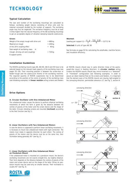
A. Circular Oscillator with One Unbalanced Motor<br />
The unbalanced motor causes the device to perform elliptical oscillating<br />
movements of which the form is given by the distance between the<br />
centres of gravity of the motor and the screen device and the shape of<br />
the latter. Circular vibrating screens are mounted (inclined) according<br />
to the their function (see fig. 1).<br />
~ 35°<br />
section A<br />
B. Linear Oscillators with Two Unbalanced Motors<br />
In case the device is supposed to perform linear oscillating movements, it<br />
is necessary to mount two unbalanced motors with rigid connection. The<br />
motors must rotate in opposite direction (to each other). The centres of<br />
gravity of the motors and the device must be on the same line, their<br />
inclina tion being generally 45° (see fig. 2).<br />
conveying direction<br />
C. Linear Oscillators with One Unbalanced Motor<br />
on Pendulum Mount<br />
If the unbalanced motor is mounted on a pendulum mount, the device’s<br />
oscil lating movements are not exactly straight-line, but slightly elliptical.<br />
Their form depends on the distance between the centres of gravity of the<br />
motor and screen device and on the shape of the latter. Drives on pen -<br />
dulum mounts may be used only on smaller devices. Their inclination is<br />
usually 45° (see fig. 3).<br />
ROSTA<br />
conveying direction<br />
54