Properties of Composite Piezoelectric Materials for Ultrasonic ...
Properties of Composite Piezoelectric Materials for Ultrasonic ...
Properties of Composite Piezoelectric Materials for Ultrasonic ...

You also want an ePaper? Increase the reach of your titles
YUMPU automatically turns print PDFs into web optimized ePapers that Google loves.
PROPERTIES OF COMPOSITE PIEZOELECTRIC MATERIALS<br />
FOR ULTRASONIC TRANSDUCERS<br />
W. A. Smith, A. A. Shaulov and B. M. Singer<br />
Philip Laboratories<br />
A Division <strong>of</strong> North American Philips Corporation<br />
Briarcliff Manor, New York 10510<br />
ABSTRACT<br />
A new spectrum <strong>of</strong> electromechanical properties are<br />
realized with composite materials made by combining<br />
a piezoelectric ceramic and a passive epoxy.<br />
we have studied disks <strong>of</strong> rod composites in which<br />
the epoxy resin holds together parallel thin rods<br />
<strong>of</strong> piezoelectric ceramic oriented perpendicular to<br />
the faces. If the lateral spatial periodicity <strong>of</strong><br />
the structure is smaller than all the relevant a-<br />
coustic wavelengths, these composites behave as a<br />
homogeneous piezoelectric with new "effective'<br />
material parameters. For ultrasonic transducer<br />
applications we can engineer the structure to make<br />
materials whose electromechanical coupling is<br />
higher and acoustic impedance is lower than those<br />
<strong>of</strong> conventional piezoelectric ceramics.<br />
ical properties better suited to medical ultrasound<br />
transducers. Such composite materials are<br />
built up by combining a piezoelectric ceramic with<br />
a passive polymer. A great variety <strong>of</strong> structures<br />
have been made; each <strong>of</strong>fers new options in material<br />
properties. The class <strong>of</strong> structures we report<br />
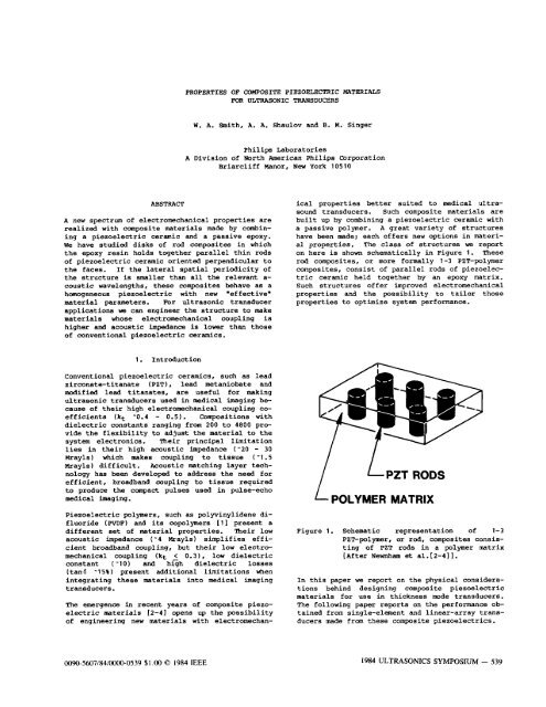
on here is shown schematically in Figure 1. These<br />
rod composites, or more <strong>for</strong>mally 1-3 PZT-polymer<br />
composites, consist <strong>of</strong> parallel rods <strong>of</strong> piezoelectric<br />
ceramic held together by an epoxy matrix.<br />
Such structures <strong>of</strong>fer improved electromechanical<br />
properties and the possibility to tailor those<br />
properties to optimize system per<strong>for</strong>mance.<br />
1. Introduction<br />
Conventional piezoelectric ceramics, such as lead<br />
zirconate-titanate (PZT), lead metaniobate and<br />
modified lead titanates, are useful <strong>for</strong> making<br />
ultrasonic transducers used in medical imaging because<br />
<strong>of</strong> their high electromechanical coupling coefficients<br />
(kt -0.4 - 0.5). Compositions with<br />
dielectric constants ranging from 200 to 4800 provide<br />
the flexibility to adjust the material to the<br />
system electronics. Their principal limitation<br />
lies in their high acoustic impedance ('20 - 30<br />
Mrayls) which makes coupling to tissue (-1.5<br />
Mrayls) difficult. Acoustic matching layer technology<br />
has been developed to address the need <strong>for</strong><br />
efficient, broadband coupling to tissue required<br />
to produce the compact pulses used in pulse-echo<br />
medical imaging.<br />
<strong>Piezoelectric</strong> polymers, such as polyvinylidene difluoride<br />
(PVDF) and its copolymers [l] present a<br />
different set <strong>of</strong> material properties. Their low<br />
acoustic impedance (-4 Mrayls) simplifies efficient<br />
broadband coupling, but their low electromechanical<br />
coupling (kt 5 0.31, low dielectric<br />
constant (-10) and high dielectric losses<br />
(tan6 -15% 1 present additional limitations when<br />
integrating these materials into medical imaging<br />
transducers.<br />
The emergence in recent years <strong>of</strong> composite piezoelectric<br />
materials 12-41 opens up the possibility<br />
<strong>of</strong> engineering new materials with electromechan-<br />
LPZT RODS<br />
POLYMER MATRIX<br />
Figure 1. Schematic representation <strong>of</strong> 1-3<br />
PZT-polymer, or rod, composites consisting<br />
<strong>of</strong> PZT rods in a polymer matrix<br />
[After Newnham et al.t2-411.<br />
In this paper we report on the physical considerations<br />
behind designing composite piezoelectric<br />
materials <strong>for</strong> use in thickness mode transducers.<br />
The following paper reports on the per<strong>for</strong>mance obtained<br />
from single-element and linear-array transducers<br />
made from these composite piezoelectrics.<br />
0090-5607/84/oooO-0539 $1 .OO 0 1984 IEEE 1984 ULTRASONICS SYMPOSIUM - 539
Smith, W.A.<br />
2. Material Fabrication<br />
A number <strong>of</strong> techniques have been developed to<br />
fabricate rod composites both at Pennsylvania<br />
State University [4,51 and within our own lab<br />
[61. Figure 2 illustrates one method based on<br />
dicing part-way through a solid disk <strong>of</strong> PZT with a<br />
multiple-blade semiconductor wafering saw. A<br />
polymer epoxy is then poured into the grooves.<br />
After curing the epoxy, the base <strong>of</strong> solid PZT is<br />
cut away leaving a thin disk consisting <strong>of</strong><br />
rectangular rods held together by the polymer<br />
similar to the structure shown schematically in<br />
Figure 1.<br />
The measurements reported in this paper were made<br />
on disks fabricated in this fashion from PZT5A<br />
[71 and Spurr epoxy [81. These are the same<br />
materials used to make the samples studied at<br />
Pennsylvania State and Stan<strong>for</strong>d Universities that<br />
are reported in the three preceding papers [9-111;<br />
so direct comparisons can be made. The spatial<br />
periodicity <strong>of</strong> these samples is about 500 microns<br />
with 250 micron square rods, i.e. approximately<br />
25% PZT by volume.<br />
3. Theory<br />
Let us first take up the question <strong>of</strong> when we can<br />
consider a rod composite structure to behave as a<br />
homogeneous material with new "effective" material<br />
constants. The preceding papers [9,10] present a<br />
detailed study <strong>of</strong> the very complex modes in rod<br />
composite disks due to stop-band resonances in the<br />
lateral periodic array <strong>of</strong> rods. For a given<br />
periodicity, there is a whole spectrum <strong>of</strong> resonant<br />
Lamb waves on a composite plate, beginning at the<br />
frequency <strong>of</strong> the first stop-band resonance. It<br />
would be a catastrophe to have these lateral<br />
resonances occur near the thickness-resonance mode<br />
<strong>of</strong> the disk that we wish to use as an ultrasonic<br />
transducer in that thickness mode. We can avoid<br />
this regime by making composite plates with a<br />
sufficiently fine lateral spatial scale, compared<br />
with the thickness, that its lateral stop-band<br />
resonances occur at frequencies well above the<br />
fundamental thickness mode <strong>of</strong> the plate. Viewed<br />
in the spatial domain, such a choice insures that<br />
all excited acoustic waves have wavelengths large<br />
compared with the lateral variations in<br />
composition. That is, <strong>of</strong> course, if we limit the<br />
excitation frequencies to be near the thickness<br />
mode frequency. In such a case the acoustic waves<br />
"average" over the unresolved fine structure much<br />
as the acoustic waves in the usual piezoelectric<br />
ceramic "average" over properties <strong>of</strong> individual<br />
ceramic grains. Thus the material can be<br />
considered an effective homogeneous piezoelectric<br />
with .new" properties if the lateral periodicity<br />
is sufficiently fine compared with its thickness.<br />
Figure 2.<br />
<strong>Composite</strong> fabrication by slicing a PZT<br />
disk part-way through in one direction<br />
and again in the perpendicular<br />
direction.<br />
We can get further physical insight into this<br />
requirement by considering the gedanken experiment<br />
shown schematically in Figure 3. Here a<br />
high-frequency pressure wave is impinging on a<br />
single PZT rod embedded in a compliant polymer<br />
plate. The polymer is s<strong>of</strong>t both under compression<br />
and shear so its surface distorts dramatically<br />
near the stiffer PZT rod. The ceramic rod thus<br />
stiffens the structure in its vicinity. This<br />
stiffening extends out some fraction <strong>of</strong> the<br />
epoxy's shear wavelength at the driving<br />
frequency. Now if the polymer plate is filled<br />
with a periodic array <strong>of</strong> PZT rods whose spacing is<br />
much smaller than this shear wavelength, the<br />
polymer is effectively "tied" to the rods. The<br />
plate then oscillates uni<strong>for</strong>mly with the ceramic<br />
and polymer moving together. Thus the pressure<br />
exerted on the epoxy is not lost but effectively<br />
transferred to the PZT rods which produce the<br />
electric response.<br />
Considering the case where the rod composite plate<br />
oscillates uni<strong>for</strong>mly near its thickness-mode<br />
resonance we can readily calculate the new<br />
"effective" material parameters describing that<br />
resonance. The easiest properties to determine<br />
are the density and dielectric constant <strong>of</strong> the<br />
composite. They are, in first order, just the<br />
average <strong>of</strong> these properties <strong>of</strong> the component<br />
phases weighted by volume fraction. For the<br />
density this is clear because it is a scalar<br />
quantity; <strong>for</strong> the dielectric permittivity it<br />
follows from simple summation <strong>of</strong> parallel<br />
capacitances.<br />
540 - 1984 ULTRASONICS SYMPOSIUM
Smith, W.A.<br />
dielectric constant. The partial lateral clamping<br />
<strong>of</strong> the rod by the polymer and the actual squeezing<br />
<strong>of</strong> the polymer by the ceramic, both serve to stiffen<br />
the composite over the first-order calculation.<br />
Figure 3.<br />
d-<br />
Usheaqn<br />
f<br />
Schematic representation <strong>of</strong> a highfrequency<br />
pressure wave impinging on a<br />
single PZT rod in a polymer plate. For<br />
a distance, d, from the rod the polymer<br />
is effectively tied to the ceramic.<br />
The elastic constant governing the thickness distortions<br />
is also just the volume-fraction weighted<br />
average <strong>of</strong> that <strong>of</strong> the component phases. This is<br />
readily seen using a parallel-springs picture much<br />
like the parallel capacitance viewpoint used to<br />
calculate the dielectric constant. Here however a<br />
judicious choice can improve the calculation with<br />
little ef<strong>for</strong>t. A compression <strong>of</strong> the plate will<br />
cause both the ceramic and the polymer to want to<br />
bulge in the lateral direction (i.e. the Poisson<br />
ratio effect 1 . Since we will operate the<br />
transducer at frequencies high compared with<br />
lateral modes <strong>of</strong> the sample as a whole, the total<br />
lateral distortion is clamped or "frozen out".<br />
The component phases, however, have lateral scales<br />
corresponding to much higher frequencies than the<br />
thickness resonance so the substructure is not<br />
laterally clamped in detail. The ceramic and<br />
polymer will compete in the lateral direction, and<br />
the much stiffer ceramic will win. Indeed, the<br />
polymer will only exert a modest degree <strong>of</strong> clamping<br />
on the ceramic rod over its behavior as a<br />
totally free rod. Thus, in first approximation,<br />
it is best to use the elastic constant describing<br />
oscillations in a laterally free PZT rod, not a<br />
laterally clamped PZT disk. For the polymer it<br />
makes little difference, since its contribution to<br />
the elastic constant <strong>of</strong> the composite is small<br />
even in first approximation.<br />
While the calculation <strong>of</strong> the density is exact,<br />
there are clearly corrections to the dielectric<br />
and elastic constants available in a more detailed<br />
theory. Flux leakage and relaxation <strong>of</strong> the<br />
lateral clamping on the rod give countervailing<br />
corrections to the ceramic's contribution to the<br />
Fram the values <strong>for</strong> the density and elastic constant,<br />
the longitudinal velocity, (c/p)'i2, and<br />
specific acoustic impedance, (pc)'I2,<br />
are readily<br />
calculated. For the velocity, the lower density<br />
and elastic constant cancel each other out and<br />
only modest change is observed from PZT behavior.<br />
For the specific acoustic impedance, the effects<br />
compound and dramatically lower values (- 4<br />
Mrayls) can be attained. The low acoustic impedance<br />
is an important advantage <strong>for</strong> rod composite<br />
piezoelectrics.<br />
The effective electromechanical coupling coefficient<br />
<strong>of</strong> the composite disk receives no direct<br />
contribution from the polymer phase, since it is<br />
not piezoelectric. In first order we can take<br />
kt <strong>for</strong> the composite to be just that <strong>of</strong> a free<br />
PZT rod (i.e. k33 <strong>for</strong> the ceramic). The partial<br />
lateral clamping <strong>of</strong> the polymer will serve to reduce<br />
the effective kt somewhat, but nevertheless<br />
it will be still significantly larger than the<br />
fully lateral-clamped value (i.e. kt) <strong>for</strong> the<br />
ceramic. By using a ceramic with high k33 significant<br />
enhancement can be obtained. The larger<br />
electromechanical coupling coefficient is another<br />
advantage <strong>for</strong> rod composite piezoelectrics.<br />
4. Fxperiment<br />
For the samples reported in this paper let us<br />
first note that the first-order theory is expected<br />
to be valid. The shear velocity <strong>of</strong> the Spurr<br />
epoxy (- 1000 m/sec) yields a shear wavelength<br />
<strong>of</strong> 2 nun near the 500 kHz thickness resonance.<br />
This is much greater than the 250 micron spacing<br />
between the rods.<br />
Table 1 shows the electromechanical properties <strong>of</strong><br />
25% PZT rod composite material along with those <strong>of</strong><br />
its component phases. A full discussion <strong>of</strong> the<br />
measurements is presented below. But let us here<br />
note that the composite's effective properties are<br />
in good agreement with predictions <strong>of</strong> the<br />
first-order theory.<br />
The remainder <strong>of</strong> this section describes, <strong>for</strong> one<br />
particular sample, a detailed experimental verification<br />
that rod composites can be accurately described<br />
as a homogeneous piezoelectric material<br />
with new "effective" material constants. The per<strong>for</strong>mance<br />
<strong>of</strong> a thickness-mode piezoelectric transducer<br />
can be accurately predicted [12] using the<br />
one-dimensional model embodied in the Mason [13]<br />
or KLM [14] equivalent circuits. Besides the<br />
transducer geometry, four material parameters are<br />
needed to predict the per<strong>for</strong>mance from a homogeneous<br />
piezoelectric material: the clamped dielectric<br />
constant, ES, the longitudinal acoustic velocity,<br />
vD, the thickness electromechanical coup<br />
ling constant, kt, and the specific acoustic<br />
impedance, Z. Three <strong>of</strong> these (ES, kt, vD)<br />
are obtained directly by measuring the frequency<br />
1984 ULTRASONICS SYMPOSIUM - 541
Smith, W.A.<br />
Table 1.<br />
Electromechanical properties <strong>of</strong> a typical<br />
250 PZT rod composite and its component<br />
materials together with the predictions<br />
<strong>of</strong> a first-order theory. The<br />
underlined quantities are the directly<br />
measured ones. The others are inferred.<br />
PZT<br />
DISK -<br />
-<br />
ET 1200<br />
PZT<br />
ROD<br />
-<br />
- 1200<br />
- SPURR<br />
- 4<br />
25% PZT<br />
COUPOSITB<br />
- E X P Z<br />
- 280 300<br />
- N A R<br />
OWE FACE N WATER<br />
pO03 k4/m3)<br />
__ 7.5<br />
- 7.5<br />
- 1.1<br />
- 2.5 2.1<br />
~ ( 1 N/m3) 0 ~ ~ 15<br />
10.8<br />
0.5<br />
2.9 3.1<br />
28.5<br />
2.4<br />
0.5 8.4<br />
02 0.4 0.6<br />
- 3.8<br />
- 2.2<br />
- 3.4 3.4<br />
FREQUENCY (MHr)<br />
- 65<br />
- 0<br />
- 60 65<br />
dependence <strong>of</strong> the electrical impedance in the<br />
vicinity <strong>of</strong> the thickness-mode resonance in a thin<br />
disk sample using either the IRE standard [15] or<br />
the impedance circle technique 1161. The acoustic<br />
impedance, Z, is also determined directly by<br />
measuring the same resonance curve but with one<br />
face <strong>of</strong> the sample in water. The losses caused by<br />
acoustic radiation into water dominate, so we<br />
obtain Z by fitting the electrical impedance to<br />
its theoretical <strong>for</strong>m,<br />
1<br />
kt2 2tan (kf/2) - j(Zo/Z)<br />
-[1-- 1 1<br />
kt 1<br />
WO - j (ZO/Z) Cot (kL)<br />
where CO = E ~ E ~ A is / ~ the clamped capacitance<br />
<strong>of</strong> the sample (area A, thickness E), k =<br />
w/vD is the propagation constant <strong>of</strong> the acoustic<br />
wave and Zo is the specific acoustic impedance<br />
<strong>of</strong> water.<br />
We have per<strong>for</strong>med these measurements using an<br />
HP4192A Impedance Analyzer controlled by an<br />
HP9825T Desktop Computer. Figures 4 and 5 show<br />
the measured resonance curves and the theoretical<br />
fit <strong>for</strong> a sample with kt = 0.60, Z = 7.5 Mrayls,<br />
ES = 200, and vD = 3400 nJsec.<br />
It is important to confirm that these materials<br />
parameters accurately describe the acoustic<br />
transduction in composite piezoelectric<br />
materials. To do this we have measured the<br />
reception sensitivity, transmission efficiency,<br />
and acoustic radiation pr<strong>of</strong>ile from an air-backed<br />
19 m disk <strong>of</strong> material. Absolute pressure<br />
measurements were made using a calibrated 1 mn<br />
Figure 4.<br />
P<br />
I<br />
- P<br />
Magnitude <strong>of</strong> the electrical impedance<br />
measured near the thickness resonance<br />
<strong>of</strong> a composite disk both in air and<br />
with one face in water.<br />
4 , I I I (<br />
- M O R Y<br />
02 0.4 0. E 0.8<br />
FREQUENCY (MHz)<br />
Figure 5. Real and imaginary parts <strong>of</strong> the<br />
electric impedance <strong>of</strong> a composite disk<br />
(with one face in water) measured near<br />
its thickness resonance plus the fitted<br />
theoretical curve which determines the<br />
mat er ial paramet er s.<br />
542 - 1984 ULTRASONICS SYMPOSIUM
Smith, W.A.<br />
diameter WDF hydrophone probe [ 1 7,18 1.<br />
Transmission efficiency is measured as the ratio<br />
<strong>of</strong> the pressure amplitude at a point in the far<br />
field along the disk's axis to the voltage<br />
amplitude across the sample. In measuring the<br />
reception sensitivity, a broadband unfocused<br />
transducer was used as a source with the sample<br />
perpendicular to its axis, well into the far<br />
field. The reception sensitivity was determined<br />
as the ratio <strong>of</strong> the open circuit voltage amplitude<br />
to the incoming pressure amplitude; minor<br />
corrections due to amplitude and phase variations<br />
<strong>of</strong> the pressure over the disk receiver were taken<br />
into account.<br />
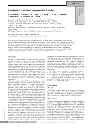
Figure 6 shows the transmission efficiency<br />
measured 12 an along the axis <strong>of</strong> the same 19 w<br />
disk whose materials constants were determined<br />
from the impedance measurements shown above.<br />
Figure 7 shows the reception sensitivity <strong>of</strong> this<br />
same sample. In both figures the theoretical fits<br />
to these absolute measurements were made using<br />
materials parameters that agree with those derived<br />
from the resonance fits; there are no other<br />
ad justable parameters. "be agreement with theory<br />
is excellent. The largest source <strong>of</strong> experimental<br />
uncertainty is the 2 2.5 dB absolute calibration<br />
<strong>of</strong> the hydrophone probe below lMHz 1181 which<br />
influences only +; the other parameters agree<br />
well within 5%.<br />
FREQUENCY (MHz)<br />
- THEORY<br />
~caowm EXPERIMENT<br />
Figure 7. Absolute reception sensitivity measured<br />
in the far field <strong>of</strong> the source (corrected<br />
<strong>for</strong> minor phase and amplitude<br />
variations), together with the theoretical<br />
fit.<br />
Figure 8 shows the acoustic radiation pr<strong>of</strong>ile<br />
measured with a 1 w diameter PZT hydrophone probe<br />
[DAPCO NPIO-11 at 490 kAz in the far field. The<br />
theoretical curve is the beam pr<strong>of</strong>ile expected <strong>for</strong><br />
a 19 rmn diameter flat-piston radiator. Again the<br />
agreement with theory is excellent.<br />
- THEORY<br />
25 , I I<br />
- TIIErnY<br />
L<br />
$<br />
Y<br />
B w<br />
Figure 8.<br />
-16 -8 0 8 16<br />
ANGLE (DEGREES)<br />
Acoustic radiation pr<strong>of</strong>ile measured in<br />
the far field <strong>of</strong> a 19 mn disk sample at<br />
490 kHz.<br />
FREQUENCY (MHz)<br />
Figure 6. Absolute transmission efficiency<br />
measured 12 cm along the axis <strong>of</strong> a 19<br />
nun diameter disk sample, together with<br />
the theoretical fit.<br />
5. Conclusions<br />
For thickness-mode ultrasonic transducers, a rod<br />
composite piezoelectric can be described as a<br />
homogeneous material with new "effective"<br />
electromechanical properties if the lateral<br />
spatial periodicity is sufficiently fine compared<br />
with the thickness. Making fine spatial scale<br />
material is the key to designing composite <strong>for</strong> use<br />
in thickness mode transducers at high frequencies.<br />
1984 ULTRASONICS SYMPOSIUM - 543
Smith, W.A.<br />
Rod composite piezoelectrics have been made which<br />
have higher electromechanical coupling coefficient<br />
(kt 2 0.6) and lower acoustic Lnpedance (5 7.5<br />
Mrayls) than conventional piezoelectric ceramics.<br />
Such a piezoelectric material is particularly useful<br />
<strong>for</strong> making ultrasonic transducers <strong>for</strong> medical<br />
imaging.<br />
6. Acknowledgements<br />
We are indebted to M. Athanas, D. Cammack, R.<br />
Dalby, D. Dorman, S . Frazier, J. Hannes, A. Pink,<br />
M. Rosar and J. Zola <strong>of</strong> Philips Laboratories <strong>for</strong><br />
their contributions in fabrication, measurement<br />
and analysis. Dr. P. J. 't Hoen, Dr. S. 0. Ishrak<br />
and Dr. E. J. Pisa <strong>of</strong> Philips Ultrasound Inc. provided<br />
valued insights into transducer and system<br />
requirements <strong>for</strong> medical imaging. This research<br />
has benefited greatly by interactions with Pr<strong>of</strong>.<br />
L. E. Cross, Dr. T. R. Gururaja, Pr<strong>of</strong>. R. E.<br />
Newnham, and Dr. W. A. Schulze at Pennsylvania<br />
State University, and with Pr<strong>of</strong>. B. A. Auld, Dr.<br />
R. L. Baer, and Pr<strong>of</strong>. B. T. Khuri-Yakub at Stan<strong>for</strong>d<br />
University. It is also good to note the<br />
seminal role <strong>of</strong> the Office <strong>of</strong> Naval Research in<br />
bringing out the potential <strong>of</strong> composite piezoelectrics<br />
by sponsoring the in-depth materials<br />
research at Pennsylvania State University.<br />
7. References<br />
7. 501A powder from <strong>Ultrasonic</strong>s Powders Inc.,<br />
South Plainfield, New Jersey fired by Nittany<br />
Piezo Ceramics, Bellefonte, Pennsylvania.<br />
8. Spurr Low Viscosity medding Medium, Polysciences<br />
Inc., Warrington, Pennsylvania.<br />
9. T. R. Gururaja, W. A. Schulze, L. E. Cross,<br />
R. E. Newnham, R. A. Auld and J. Wang,<br />
"Resonant Modes in <strong>Piezoelectric</strong> PZT Rod-<br />
Polymer <strong>Composite</strong> <strong>Materials</strong>," Proc. 1984 IEEE<br />
<strong>Ultrasonic</strong>s Symposium.<br />
10. B. A. Auld and J. Wang, "Acoustic Wave Vibrations<br />
in Periodic <strong>Composite</strong> Plates," Proc.<br />
1984 IEEE <strong>Ultrasonic</strong>s Symposium.<br />
11. T. R. Gururaja, W. A. Schulze, L. E. Cross<br />
and R. E. Newnham, "<strong>Ultrasonic</strong> <strong>Properties</strong> <strong>of</strong><br />
<strong>Piezoelectric</strong> PZT Rod-Polymer <strong>Composite</strong><br />
<strong>Materials</strong>," Proc. 1984 IEEE <strong>Ultrasonic</strong>s<br />
symposium.<br />
12. A. R. Selfridge, "The Design and Fabrication<br />
<strong>of</strong> <strong>Ultrasonic</strong> Transducers and Transducer<br />
Arrays," Ph.D. Thesis, Stan<strong>for</strong>d<br />
University, July 1982 and citations therein.<br />
13. W. P. Mason, Electromechanical Transducers<br />
and Wave Filters, Second Edition, van<br />
Nostrand-Reinhold, Princeton, New Jersey,<br />
1948.<br />
1.<br />
2.<br />
3.<br />
4.<br />
5.<br />
6.<br />
H. Ohigashi, K. Koga, M. Suzuki, T.<br />
Nakanishi, K. Kimura and N. Hashimoto,<br />
"<strong>Piezoelectric</strong> and Ferroelectric <strong>Properties</strong><br />
<strong>of</strong> P(VDF-TrFE) Copolymers and their Application<br />
to <strong>Ultrasonic</strong> Transducers," Ferroelectrics<br />
60, 263 (1984).<br />
R. E. Newnham, A. Safari, J. Giniewicz and<br />
B. H. FOX, "<strong>Composite</strong> <strong>Piezoelectric</strong> Sensors,"<br />
Ferroelectrics in press (1984).<br />
A. Safari, R. E. Newnham, L. E. Cross and<br />
W. A. Schulze, "Per<strong>for</strong>ated PZT-Polymer Corn<br />
posites <strong>for</strong> <strong>Piezoelectric</strong> Transducer Applications,"<br />
Ferroelectrics 41, 197 (1982).<br />
R. E. Newnham, L. J. Bowen, K. A. Klicker<br />
and L. E. Cross, "<strong>Composite</strong> <strong>Piezoelectric</strong><br />
Transducers," Mat. Eng. 2, 93 (1980).<br />
H. P. Savakus, K. A. Klicker and R. E.<br />
Newnham, "PZT-Epoxy <strong>Piezoelectric</strong> Transducers:<br />
A Simplified Fabrication Procedure",<br />
Mat. Res. Bul. 2, 677 (1981).<br />
J. Zola, D. Dorman and W. A. Smith, to be<br />
published.<br />
14. D. Leedom, R. Krimholtz, and G. Matthaei,<br />
"Equivalent Circuits <strong>for</strong> Transducers having<br />
Arbitrary Even-or Odd-Symmetry <strong>Piezoelectric</strong><br />
Excitation", IEEE Trans. Sonics Ultrason.<br />
SO-18, 128 (1971).<br />
15. IRE Standards on <strong>Piezoelectric</strong> Crystals,<br />
Proc. IRE E, 1161 (1961).<br />
16. R. Holland and E. P. EerNisse, "Accurate<br />
Measurement <strong>of</strong> Coefficient in a Ferroelectric<br />
Ceramic", IEEE Trans. Sonics Ultrason. SU-16,<br />
173 (1969).<br />
17. P. A. Lewin, "Miniature <strong>Piezoelectric</strong> Polymer<br />
<strong>Ultrasonic</strong> Hydrophone Probes", Utrasonics 3,<br />
2 13 ( 1981 1 , and "Calibration and Per<strong>for</strong>mance<br />
Evaluation <strong>of</strong> Miniature <strong>Ultrasonic</strong> Hydrophones<br />
using Time Delay Spectroscopy", Proc.<br />
1981 IEEE Ultasonics Symposium, 660 (1 981 1.<br />
18. Lewin Probe 530, Danish Institute <strong>of</strong> <strong>of</strong><br />
Biomedical Engineering, DK-2600 Glostrup,<br />
Denmark. The extended calibration range, 150<br />
kHz - lMhz, had a quoted accuracy <strong>of</strong> only<br />
* 2.5 dB; in our experience it was rather<br />
more accurate.<br />
544 - 1984 ULTRASONICS SYMPOSIUM