Superconducting magnetic energy storage device operating at liquid ...
Superconducting magnetic energy storage device operating at liquid ...
Superconducting magnetic energy storage device operating at liquid ...

You also want an ePaper? Increase the reach of your titles
YUMPU automatically turns print PDFs into web optimized ePapers that Google loves.
Cryogenics 39 (1999) 53–58<br />
<strong>Superconducting</strong> <strong>magnetic</strong> <strong>energy</strong> <strong>storage</strong> <strong>device</strong> <strong>oper<strong>at</strong>ing</strong> <strong>at</strong><br />
<strong>liquid</strong> nitrogen temper<strong>at</strong>ures<br />
A. Friedman * , N. Shaked, E. Perel, M. Sinvani, Y. Wolfus, Y. Yeshurun<br />
Institute for Superconductivity, Department of Physics, Bar-Ilan University, Ram<strong>at</strong>-Gan 52900, Israel<br />
Received 7 July 1998; received in revised form 7 November 1998<br />
Abstract<br />
A labor<strong>at</strong>ory-scale superconducting <strong>energy</strong> <strong>storage</strong> (SMES) <strong>device</strong> based on a high-temper<strong>at</strong>ure superconducting coil was<br />
developed. This SMES has three major distinctive fe<strong>at</strong>ures: (a) it oper<strong>at</strong>es between 64 and 77K, using <strong>liquid</strong> nitrogen (LN 2 ) for<br />
cooling; (b) it uses a ferro<strong>magnetic</strong> core with a variable gap to increase the stored <strong>energy</strong> while retaining the critical current value;<br />
(c) it has the option for simultaneous <strong>energy</strong> charge and discharge which increases the power available <strong>at</strong> the SMES output by a<br />
factor of 2 when <strong>oper<strong>at</strong>ing</strong> as a converter. The present prototype of <strong>liquid</strong> nitrogen <strong>oper<strong>at</strong>ing</strong> SMES stores 130 J <strong>at</strong> 64K and<br />
60 J <strong>at</strong> 77K. © 1999 Elsevier Science Ltd. All rights reserved.<br />
Keywords: High T c superconductors; Critical current density; SMES; Power applic<strong>at</strong>ions<br />
1. Introduction<br />
A <strong>device</strong> for storing electro<strong>magnetic</strong> <strong>energy</strong> is an<br />
<strong>at</strong>tractive potential applic<strong>at</strong>ion for high-temper<strong>at</strong>ure<br />
superconductors (HTS). The feasibility of a high-temper<strong>at</strong>ure<br />
superconducting <strong>magnetic</strong> <strong>energy</strong> <strong>storage</strong> (HT-<br />
SMES) <strong>device</strong> has been extensively discussed [1–4] and<br />
a few experimental projects aiming <strong>at</strong> <strong>oper<strong>at</strong>ing</strong> temper<strong>at</strong>ures<br />
of 30K were reported [5–8].<br />
The two main obstacles delaying the development of<br />
aLN 2 oper<strong>at</strong>ed SMES are the rel<strong>at</strong>ively low critical current<br />
density J c of the BSCCO wires and the strong<br />
decrease of J c with <strong>magnetic</strong> field <strong>at</strong> LN 2 temper<strong>at</strong>ure.<br />
These two factors result in low values for the stored<br />
<strong>energy</strong>, making the <strong>liquid</strong> nitrogen oper<strong>at</strong>ed SMES inefficient<br />
i.e. with poor r<strong>at</strong>io of the maximal <strong>energy</strong> stored<br />
in the coil to the power required for its cooling. Calcul<strong>at</strong>ions<br />
[9] show th<strong>at</strong> for BSCCO-based SMES,<br />
maximum efficiency is achieved <strong>at</strong> about 30K. We report<br />
here on an HT-SMES, based on HTS coil made of Bi–<br />
Sr–Ca–Cu–O (Bi-2223) wires, <strong>oper<strong>at</strong>ing</strong> <strong>at</strong> <strong>liquid</strong> nitrogen<br />
(LN 2 ) temper<strong>at</strong>ures. In order to improve the<br />
efficiency of this SMES we have introduced a ferro<strong>magnetic</strong><br />
core and designed a special converter circuit. The<br />
* Corresponding author.<br />
core, made of lamin<strong>at</strong>ed iron surrounding the HTS coil,<br />
contributes a gain of 14 and 6 in the stored <strong>energy</strong><br />
<strong>at</strong> 77 and 64K, respectively. Moreover, the core is<br />
designed to prevent the coil from being exposed to the<br />
<strong>magnetic</strong> self-fields, allowing for rel<strong>at</strong>ively high oper<strong>at</strong>ion<br />
currents in the presence of high self-fields. A specially<br />
designed converter enables simultaneous charge and<br />
discharge of the HTS coil, adding another factor of <br />
2 in the transmitted power. The details of this SMES<br />
and its oper<strong>at</strong>ional st<strong>at</strong>es are described below.<br />
2. SMES structure<br />
2.1. The HTS coil<br />
The three double pancakes coil, purchased from<br />
American Superconductors Corpor<strong>at</strong>ion (ASC) is made<br />
of 160 m multifilamentary silver-she<strong>at</strong>hed BSCCO wire.<br />
Its critical current (1 V/cm criterion) is 22.2 A <strong>at</strong> 77K.<br />
The <strong>energy</strong> <strong>storage</strong> capacity <strong>at</strong> this temper<strong>at</strong>ure is 4.2 J.<br />
Table 1 summarizes the characteristics of this coil.<br />
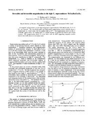
Typical I–V curves for the coil are shown in Fig. 1<br />
for 64 and 77K. All measured I–V curves between 52<br />
and 77K exhibit a power law dependence: V <br />
V 0 (I/I c ) n , with a power n between 10 and 12. The critical<br />
current, I c , was found to increase, approxim<strong>at</strong>ely lin-<br />
0011-2275/99/$ - see front m<strong>at</strong>ter © 1999 Elsevier Science Ltd. All rights reserved.<br />
PII: S0011-2275(98)00126-X
54 A. Friedman et al. /Cryogenics 39 (1999) 53–58<br />
Table 1<br />
Characteristics of the HTS coil<br />
Inside diameter (mm) 194<br />
Outside diameter (mm) 244<br />
Height (mm) 18<br />
Number of turns 250<br />
Conductor length (m) 160<br />
Inductance (mH) 17<br />
Critical current @ 77K (A) 22.2<br />
Maximal amperturns @ 77K 5550<br />
Stored <strong>energy</strong> @ 77K (J) 4.2<br />
In the present work we have investig<strong>at</strong>ed the gain in<br />
the stored <strong>energy</strong> for a ‘closed core’ configur<strong>at</strong>ion. In<br />
this configur<strong>at</strong>ion, the core occupies the volume both<br />
inside and outside the coil. This prevents flux lines from<br />
leaking out of the core increasing the field <strong>at</strong> the coil<br />
site. Energy gain calcul<strong>at</strong>ions for several geometrical<br />
shapes of closed cores are given elsewhere [14]. To illustr<strong>at</strong>e<br />
the conclusions from these calcul<strong>at</strong>ions we focus<br />
here on a special case of a closed core namely, the ‘pot<br />
core’ configur<strong>at</strong>ion in which the cross section S 0 along<br />
the flux p<strong>at</strong>h is kept constant, so th<strong>at</strong> the ‘leakage’ of<br />
flux out of the core is negligible.<br />
The maximal <strong>energy</strong> stored in a coil surrounded by a<br />
nearly s<strong>at</strong>ur<strong>at</strong>ed pot core can be estim<strong>at</strong>ed [14] as<br />
U 1 2 LI2 1 2 B sINS 0 (1)<br />
Fig. 1.<br />
I–V curves of the HTS coil <strong>at</strong> the indic<strong>at</strong>ed temper<strong>at</strong>ures.<br />
early, with decreasing temper<strong>at</strong>ure, in agreement with<br />
previous reports for HTS coils [10].<br />
We also investig<strong>at</strong>ed the interplay between AC and<br />
DC currents and their influence on the measured I–V<br />
curves. We observed th<strong>at</strong> the applic<strong>at</strong>ion of a sinusoidal<br />
current component in the frequency range of 50–500 Hz,<br />
in the presence of a DC level in the range of 16–22.5 A,<br />
caused a significant increase in the DC voltage. The DC<br />
voltage increment due to the AC component was found<br />
to increase linearly with the frequency and with the DC<br />
current level, and quadr<strong>at</strong>ically with the AC amplitude.<br />
This phenomenon is discussed elsewhere [11].<br />
2.2. Ferro<strong>magnetic</strong> core<br />
The possible gain in field and <strong>energy</strong> by inserting a<br />
<strong>magnetic</strong> core into the coil was analyzed by Cha using<br />
a long solenoid approxim<strong>at</strong>ion and finite element calcul<strong>at</strong>ion<br />
[12]. The use of a ferro<strong>magnetic</strong> core inside the<br />
coil was shown to increase the stored <strong>energy</strong> only <strong>at</strong> low<br />
current densities. Morisue et al. [13] examined the gain<br />
in the stored <strong>energy</strong> for a ferro<strong>magnetic</strong> cylinder placed<br />
outside the coil with internal fields up to 4 T. While this<br />
gain was shown to be significant, their configur<strong>at</strong>ion<br />
induces an increase in the field experienced by the coil<br />
and thus a decrease in its critical current.<br />
where L is the inductance of the coil with the core, I is<br />
the current flowing in the coil, N is the number of turns<br />
and B s is the s<strong>at</strong>ur<strong>at</strong>ion <strong>magnetic</strong> induction in the core.<br />
According to Eq. (1), the <strong>energy</strong> gain due to the iron<br />
core is proportional to the increase of the inductance or,<br />
equivalently, to the induction gain.<br />
The term LI 2 /2 in Eq. (1) indic<strong>at</strong>es the importance of<br />
the interplay between the current I and the inductance<br />
L. With a ferro<strong>magnetic</strong> core the current increase may<br />
drive the core into s<strong>at</strong>ur<strong>at</strong>ion where the inductance drops<br />
dram<strong>at</strong>ically. It is therefore crucial to select an oper<strong>at</strong>ion<br />
current close to the critical current which drives the core<br />
as close as possible to the s<strong>at</strong>ur<strong>at</strong>ion point, but still in the<br />
high inductance regime. To achieve the optimal working<br />
conditions we have introduced a variable gap into the<br />
core. As the gap width increases, the coil inductance<br />
below the s<strong>at</strong>ur<strong>at</strong>ion decreases. This allows for larger<br />
currents in the coil resulting in a total increase in the<br />
stored <strong>energy</strong>. By varying the gap we are able to oper<strong>at</strong>e<br />
the same construction <strong>at</strong> different temper<strong>at</strong>ures i.e. different<br />
values of the critical current. For technical<br />
reasons, in the present work the core occupies only 40%<br />
of the optimal volume of a pot-core configur<strong>at</strong>ion. The<br />
expected <strong>energy</strong> gain for 100% of the available volume<br />
is thus larger by a factor of 2. The characteristics of<br />
the core used in our <strong>device</strong> are summarized in Table 2.<br />
The d<strong>at</strong>a presented in Table 2 might suggest th<strong>at</strong> the<br />
<strong>energy</strong> gain decreases with increasing stored <strong>energy</strong>. It<br />
is important to note th<strong>at</strong> the <strong>energy</strong> gain obtained by the<br />
core insertion strongly depends on the <strong>magnetic</strong> field of<br />
the coil without a core. To obtain a significant gain <strong>at</strong><br />
low temper<strong>at</strong>ures where the critical current and the<br />
stored <strong>energy</strong> are high it is necessary to design the coil<br />
to have a low self induction. This conclusion will also<br />
hold for future HTS wires which will probably offer<br />
much higher critical currents <strong>at</strong> high temper<strong>at</strong>ures.<br />
The core was made of thin sheets of commercial silicon<br />
steel formed into a standard C-core shape. Pairs of
A. Friedman et al. /Cryogenics 39 (1999) 53–58<br />
55<br />
Table 2<br />
Parameters of the core<br />
52K 64K 77K<br />
Air gap (mm) 13.3 9 4.1<br />
Core cross-section (m 2 ) 0.013 0.013 0.013<br />
Critical current (A) 72 49 22.2<br />
Energy without core (J) 44 20.4 4.2<br />
Energy with core (J) 193 131 59.4<br />
Energy gain E/E 0 4.4 6.4 14.1<br />
Expected gain for 100% volume 9.3 13.6 30<br />
Inductance without core (H) 0.017 0.017 0.017<br />
Inductance with core (H) 0.075 0.11 0.24<br />
Maximum field with core (T) 1.7 1.7 1.7<br />
Maximum field without core (T) 0.39 0.27 0.12<br />
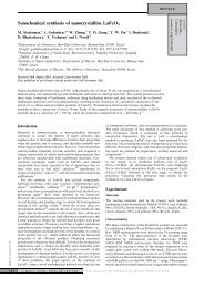
Fig. 2. The coil with the core (for clarity some of the C-cores are<br />
removed).<br />
these C-cores form rings surrounding the coil. PVC spacers<br />
were inserted between the C-cores to form the<br />
appropri<strong>at</strong>e gap <strong>at</strong> the desired <strong>oper<strong>at</strong>ing</strong> temper<strong>at</strong>ure.<br />
Fig. 2 shows a photograph of the coil and the core. For<br />
clarity we removed several of the C-core elements.<br />
2.3. Electric circuit<br />
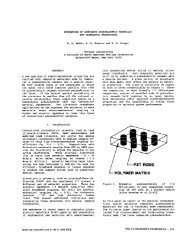
The electric circuit of our SMES <strong>device</strong> is sketched<br />
in Fig. 3. An important part of the circuit is the converter<br />
which gener<strong>at</strong>es positive and neg<strong>at</strong>ive voltage pulses to<br />
charge and discharge the superconducting coil. Two<br />
capacitor arrays, <strong>at</strong> the charger (C1) and <strong>at</strong> the load (C2),<br />
are used for the conversion of voltage to current in the<br />
coil, and vice versa. The coil is connected to four<br />
switches (Fig. 3), forming an open bridge configur<strong>at</strong>ion,<br />
and protected against overvoltage th<strong>at</strong> might occur during<br />
a fault. The switches are responsible for the different<br />
basic st<strong>at</strong>es of oper<strong>at</strong>ion. When switches 1 and 4 are<br />
closed and 2 and 3 are open, the superconducting coil<br />
is charged from the DC power source. When switches<br />
2 and 3 are closed and 1 and 4 are open, the discharge<br />
st<strong>at</strong>e is obtained. In this st<strong>at</strong>e a current is withdrawn from<br />
the coil and fed into the load capacitor to cre<strong>at</strong>e the load<br />
voltage. When switches 1 and 3 are closed and 2 and 4<br />
are open the coil is in the ‘persistent’ st<strong>at</strong>e and the current<br />
flows in a closed loop within the superconducting<br />
coil. The persistent st<strong>at</strong>e is set as an intermedi<strong>at</strong>e st<strong>at</strong>e<br />
when charge or discharge st<strong>at</strong>es are not required. The<br />
switches settings for the different st<strong>at</strong>es are summarized<br />
in Table 3.<br />
To reduce <strong>energy</strong> losses in the converter, most of its<br />
elements were immersed in <strong>liquid</strong> nitrogen. The resistance<br />
of the switches drops from 7 m <strong>at</strong> room temper<strong>at</strong>ure<br />
to 2 m <strong>at</strong> LN 2 temper<strong>at</strong>ures. As shown in Table 3<br />
and Fig. 3, switch 2 plays the role of a diode. We have<br />
found th<strong>at</strong> MOSFET transistors exhibit low resistance in<br />
comparison with other kinds of electronic switches and<br />
diodes <strong>at</strong> LN 2 temper<strong>at</strong>ures. Two kinds of capacitors<br />
were used as charger and load capacitors. One capacitors<br />
bank, which carries high currents, was immersed in the<br />
Fig. 3.<br />
Electric circuit of the SMES.<br />
Table 3<br />
Switches settings for the various oper<strong>at</strong>ion st<strong>at</strong>es of the SMES<br />
St<strong>at</strong>e S1 S2 S3 S4<br />
Charge Closed Open Open Closed<br />
Persistent Closed Open Closed Open<br />
Discharge Open Closed Closed Open<br />
Through Open Closed Open Closed
56 A. Friedman et al. /Cryogenics 39 (1999) 53–58<br />
LN 2 to reduce the losses in the wires. For this bank we<br />
have used polyester capacitors th<strong>at</strong> have low <strong>energy</strong> density<br />
but they maintain their capacitance <strong>at</strong> 77K. The<br />
remaining part—tantalum capacitors—were placed in<br />
the upper part of the dewar <strong>at</strong> temper<strong>at</strong>ure of about 0°C.<br />
The logic th<strong>at</strong> governs the above switching circuit is<br />
described in Fig. 4. The SMES can also oper<strong>at</strong>e in a<br />
converter mode in which the coil is autom<strong>at</strong>ically<br />
switched between the three <strong>oper<strong>at</strong>ing</strong> st<strong>at</strong>es according to<br />
the load voltage and the coil current conditions. The field<br />
and current probes sense actually the amount of the electro<strong>magnetic</strong><br />
<strong>energy</strong> stored in the SMES. The reading of<br />
these sensors is compared with two limit values <strong>at</strong> the<br />
compar<strong>at</strong>ors. Once the coil current decreases below the<br />
lower limit value, the controller sets the switches into<br />
the charge st<strong>at</strong>e. The charge st<strong>at</strong>e is maintained until the<br />
current achieves its preset upper value. The voltage<br />
sensor senses the voltage across the load. This value is<br />
again compared with two limiting values. Below the<br />
minimal value, the discharge st<strong>at</strong>e is set until the load<br />
voltage reaches its maximum value. The limiting values<br />
of the coil current and the load voltage can be set by<br />
the user. Between these two st<strong>at</strong>es, when no charge or<br />
discharge is required, the current circul<strong>at</strong>es in the coil.<br />
In this persistent st<strong>at</strong>e the loss of <strong>energy</strong> depends on<br />
the coil current and on the resistance of switches 1 and<br />
3. At the critical current <strong>at</strong> 77K this loss is about 1 W.<br />
To compens<strong>at</strong>e for the <strong>energy</strong> loss the coil is charged<br />
with 1 ms pulses of 10 V <strong>at</strong> a frequency of 5 Hz.<br />
A unique fe<strong>at</strong>ure of our SMES <strong>device</strong> <strong>oper<strong>at</strong>ing</strong> as a<br />
converter is the ability for a simultaneous<br />
charge/discharge oper<strong>at</strong>ion [15]. In this improved mode,<br />
charging the HTS coil can overlap its discharging. The<br />
benefit of this configur<strong>at</strong>ion is clear: the independent<br />
oper<strong>at</strong>ion of the charge/discharge st<strong>at</strong>es enables the dur<strong>at</strong>ion<br />
of each st<strong>at</strong>e to be stretched up to a full cycle. For<br />
the common case, when the charger voltage is equal to<br />
the output DC voltage, this doubles the available power<br />
<strong>at</strong> the <strong>device</strong> output, while the coil dimensions and oper-<br />
<strong>at</strong>ion costs remain unchanged. The simultaneous<br />
charge/discharge st<strong>at</strong>e is achieved when switches 2 and<br />
4 are closed and switches 1 and 3 are open. This st<strong>at</strong>e<br />
appears in Table 3 as a ‘through’ st<strong>at</strong>e. It is important<br />
to note th<strong>at</strong> in this st<strong>at</strong>e charging and discharging are<br />
still independent.<br />
2.4. Cryogenics<br />
The benefits of LN 2 oper<strong>at</strong>ion arise from the increase<br />
of cooling efficiency with the increase of the oper<strong>at</strong>ion<br />
temper<strong>at</strong>ure and from the excellent thermal contact<br />
between the coolant and the HTS coil. On the other<br />
hand, the critical current drops dram<strong>at</strong>ically with the<br />
increase of temper<strong>at</strong>ure and field, resulting in a decrease<br />
in the amount of stored <strong>energy</strong>. It is, thus, necessary to<br />
balance between these two conflicting effects in order<br />
to find the optimum oper<strong>at</strong>ion temper<strong>at</strong>ure. Following<br />
Stephanblome, Kellers and Kleimaier (SKK) [9], we<br />
define a ‘figure of merit’ for the SMES as the r<strong>at</strong>io of<br />
stored <strong>energy</strong> and the power required to cool the system.<br />
The stored <strong>energy</strong> is given by<br />
0.5LI 2 c<br />
and the cooling power is taken to be proportional to th<strong>at</strong><br />
of an ideal Carnot machine i.e. T/(T RT T), where T is<br />
the <strong>oper<strong>at</strong>ing</strong> temper<strong>at</strong>ure and T RT is the room temper<strong>at</strong>ure.<br />
From the measured I c (T), and from the known temper<strong>at</strong>ure<br />
dependence of the cooling power of the Carnot<br />
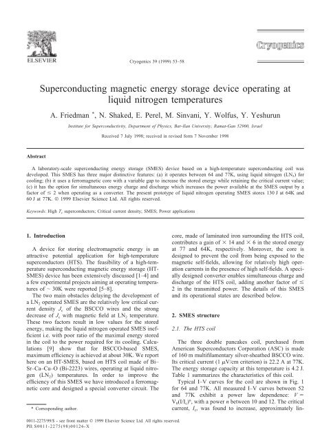
refriger<strong>at</strong>or, SKK calcul<strong>at</strong>ed the figure of merit for an<br />
HTS coil as a function of temper<strong>at</strong>ure. This figure of<br />
merit exhibits a maximum around 30K (circles in Fig.<br />
5). SMES oper<strong>at</strong>ion is practical between the 3 db point<br />
i.e. 8–62K. This situ<strong>at</strong>ion is significantly changed with<br />
the introduction of iron core where the dependence of<br />
Fig. 4.<br />
Control circuit of the converter.<br />
Fig. 5. Figure of merit for the HTS coil with () and without ()<br />
<strong>magnetic</strong> core, as a function of temper<strong>at</strong>ure.
A. Friedman et al. /Cryogenics 39 (1999) 53–58<br />
57<br />
the stored <strong>energy</strong> on the oper<strong>at</strong>ion current becomes<br />
weaker (see Table 2). As a result, the calcul<strong>at</strong>ed figure<br />
of merit (squares in Fig. 5) exhibits a maximum around<br />
50K, upwarding the practical range (between the 3 db<br />
points) to 15–77K, overlapping with the regime of<br />
LN 2 temper<strong>at</strong>ures.<br />
The HTS coil, the core and part of the electric circuit<br />
(marked in a rectangular frame in Fig. 3) are immersed<br />
in LN 2 . While <strong>oper<strong>at</strong>ing</strong>, the he<strong>at</strong> gener<strong>at</strong>ed by the<br />
SMES causes additional losses of 0.1 l/h, which is about<br />
30% of the overall cooling losses in our dewar.<br />
The main sources for the oper<strong>at</strong>ion losses are the<br />
ohmic components in the <strong>device</strong>. We have therefore<br />
selected electric components th<strong>at</strong> are suitable for oper<strong>at</strong>ion<br />
<strong>at</strong> LN 2 temper<strong>at</strong>ures. The losses due to these<br />
components are much lower <strong>at</strong> low temper<strong>at</strong>ures than <strong>at</strong><br />
room temper<strong>at</strong>ure.<br />
The working temper<strong>at</strong>ure was achieved by controlling<br />
the vapor pressure of the LN 2 . The SMES oper<strong>at</strong>ion was<br />
tested between 52K (solid nitrogen) and 77K. Although<br />
pumping adds to the cost of oper<strong>at</strong>ion, it adds flexibility<br />
in choosing the working temper<strong>at</strong>ure, allowing for an<br />
increase in the stored <strong>energy</strong> and power.<br />
To avoid working in solid nitrogen which offers<br />
inferior thermal contact than the <strong>liquid</strong>, we have selected<br />
the oper<strong>at</strong>ion temper<strong>at</strong>ure to be 64K, which is slightly<br />
above the triple point of nitrogen (T 63.2K). This temper<strong>at</strong>ure<br />
is achieved <strong>at</strong> a vapor pressure of about<br />
100 Torr th<strong>at</strong> is accessible by a low power-consuming<br />
rotary vacuum pump. The <strong>liquid</strong> st<strong>at</strong>e of nitrogen<br />
ensures ideal cooling conditions of the coil and other<br />
elements of the electric circuit.<br />
3. Oper<strong>at</strong>ion<br />
Integr<strong>at</strong>ion of the components described above results<br />
in a SMES <strong>device</strong> <strong>oper<strong>at</strong>ing</strong> in the temper<strong>at</strong>ure range<br />
between 64 and 77K with a stored <strong>energy</strong> of up to 130 J<br />
(<strong>at</strong> 64K). This <strong>device</strong> supplies a stable DC voltage to<br />
the load, which does not depend on the power quality<br />
of the input AC line.<br />
For a persistent current of 15 A the losses per second<br />
<strong>at</strong> 77K are, on the average, 0.5% of the stored <strong>energy</strong>.<br />
These losses are mainly a result of the ohmic components<br />
of the circuit. At this current, the intrinsic losses<br />
of the superconducting coil are two orders of magnitude<br />
less than the ohmic losses and are negligible.<br />
Fig. 6 demonstr<strong>at</strong>es the oper<strong>at</strong>ion of the SMES <strong>at</strong><br />
77K. The first 2 s show its oper<strong>at</strong>ion as a converter, with<br />
a load of 6 W. In this mode, <strong>energy</strong> of 50 J is stored in<br />
the coil while pulses of neg<strong>at</strong>ive and positive voltage,<br />
shown in the lower left part of the figure, charge and<br />
discharge the coil. The need for a charge or discharge<br />
pulse is determined by the control circuit which probes<br />
the coil current and the load voltage. Simultaneous<br />
Fig. 6. Oper<strong>at</strong>ion of the SMES <strong>device</strong> <strong>at</strong> 77K as a function of time.<br />
The upper curve is a record of the load voltage. Charge (neg<strong>at</strong>ive) and<br />
discharge (positive) pulses are shown in the lower part of the figure.<br />
The middle curve records the coil current which is proportional to the<br />
square root of the stored <strong>energy</strong>.<br />
appearance of charge and discharge pulses are apparent<br />
in the figure. After approxim<strong>at</strong>ely 2 s the SMES was disconnected<br />
from the AC line in order to simul<strong>at</strong>e a power<br />
failure. Fig. 6 shows th<strong>at</strong> while the charge pulses are<br />
stopped, the discharge pulses continue so th<strong>at</strong> the voltage<br />
across the load (the upper curve in the figure) is kept<br />
constant. As the <strong>energy</strong> stored in the coil decreases<br />
(middle curve), the frequency of the discharge pulses<br />
increase because each pulse converts less <strong>energy</strong>. When<br />
the stored <strong>energy</strong> reaches a predefined lower limit (in<br />
our case it is 4% of the stored <strong>energy</strong>), the SMES oper<strong>at</strong>ion<br />
is stopped and the output voltage drops to zero. It<br />
is important to note th<strong>at</strong> throughout all the time of SMES<br />
oper<strong>at</strong>ion the output voltage remains constant. The ripple<br />
seen in the voltage curve (upper curve) is a user defined<br />
value and may be set to a value as low as required. For<br />
a lower ripple value the discharging pulses will become<br />
narrower but more frequent. In this case losses in the<br />
SMES <strong>device</strong> grow as a result of the increase in the r<strong>at</strong>e<br />
of switching oper<strong>at</strong>ions.<br />
4. Summary<br />
We have designed, built and tested a prototype of<br />
SMES <strong>oper<strong>at</strong>ing</strong> in the temper<strong>at</strong>ure range between 64<br />
and 77K using <strong>liquid</strong> nitrogen cooling. This method of<br />
cooling offers a good thermal contact between the coolant<br />
and the <strong>device</strong>, it provides good thermal stability and<br />
homogeneity, and therefore is suitable for large scale<br />
applic<strong>at</strong>ions.<br />
We have used a ferro<strong>magnetic</strong> core to increase the<br />
stored <strong>energy</strong> in our SMES. A variable gap was intro-
58 A. Friedman et al. /Cryogenics 39 (1999) 53–58<br />
duced to m<strong>at</strong>ch the <strong>device</strong> inductance with the critical<br />
currents <strong>at</strong> different temper<strong>at</strong>ures. Calcul<strong>at</strong>ions for the<br />
present experiment suggest a factor of 30 in the <strong>energy</strong><br />
gain <strong>at</strong> 77K for optimal core design.<br />
The insertion of <strong>magnetic</strong> core should be considered<br />
carefully in every SMES <strong>device</strong>. For low temper<strong>at</strong>ures,<br />
the gain in the stored <strong>energy</strong> may be low and the core<br />
may become large and costly. On the other hand, it is<br />
clear th<strong>at</strong> for high temper<strong>at</strong>ure oper<strong>at</strong>ion with the present<br />
wire technology the <strong>energy</strong> gain is much higher, hence<br />
the cost of the core and its additional weight are worthwhile.<br />
A converter circuit was designed to convert the current<br />
stored in the coil to a constant voltage across the<br />
load. It allows also the oper<strong>at</strong>ion of the SMES as a DC–<br />
DC converter with simultaneous charging and discharging<br />
pulses, yielding an increase of up to a factor 2 in<br />
the power th<strong>at</strong> can be supplied by the <strong>device</strong>. The possibility<br />
for simultaneous charge and discharge oper<strong>at</strong>ion<br />
may contribute to any converter <strong>device</strong> using a superconducting<br />
coil [15].<br />
Acknowledgements<br />
We thank Gadi Pinkovich for help in the converter<br />
construction. We also thank J. Kellers and A.P. Malozemoff<br />
of ASC Inc. for useful discussions and for sharing<br />
with us available inform<strong>at</strong>ion. The Ministry of Energy<br />
and Infrastructure supported this work under contract no.<br />
93-11-039. A.F. acknowledges a support from the Ministry<br />
of Sciences and Humanities under contract no. 6781-<br />
1-95.<br />
References<br />
[1] Eyssa YM, Abdelsalam MK, Boom RW, McIntosh GE. Cryogenics<br />
1988;33:69–75.<br />
[2] Schoenung SM, Bieri RL, Meier WR, Bickel TC. IEEE Transactions<br />
in Applied Superconductivity 1993;3:200–3.<br />
[3] Schoenung SM, Meier WR, Fagaly RL, Heiberger M, Stephens<br />
RB, Stephens J, Leuer JA, Guzman RA. IEEE Transactions in<br />
Applied Superconductivity 1993;8:33–9.<br />
[4] Akita S, Wachi Y, Meguro S, Saito T, Kazuhiro U, Kazuhiko N,<br />
Takakazu S. In: Design Study of High-T c SMES. Supporo, 1996.<br />
[5] American Superconductors, Inc., Transforming the grid. Annual<br />
Report, 1996.<br />
[6] American Superconductors Inc., Revolutionizing the way the<br />
world manages <strong>energy</strong>. Annual Report, 1997.<br />
[7] Kalsi SS, Aized D, Connor B, Snitchler G, Campbell J, Schwall<br />
RE, Kellers J. IEEE Transactions in Applied Superconductivity<br />
1997;7:971–6.<br />
[8] Paasi J, Lahtinen M, Lehtonen J, Mikkonen R, Söderlund L, Connor<br />
B, Kalsi SS. Proc. of MT-15 Conference, Beijing, China,<br />
October 20–24, 1997:781–4.<br />
[9] Stephanblome T, Kellers J, Kleimaier M. Priv<strong>at</strong>e communic<strong>at</strong>ion,<br />
1995.<br />
[10] Ueyama M, Ohkura K, Kobayashi S, Muranaka K, Kaneko T,<br />
Hik<strong>at</strong>a T, Hayashi K, S<strong>at</strong>o K. In: Proceedings of the 7th Intern<strong>at</strong>ional<br />
Symposium on Superconductivity, (ISS94), Japan, 1995,<br />
p. 847.<br />
[11] Shaked N, Al-Omari IA, Friedman A, Wolfus Y, Sinvani M,<br />
Shaulov A, Yeshurun Y. Applied Physics Letters<br />
1998;73:3932–4.<br />
[12] Cha YS. Journal of Applied Physics 1993;73:6787.<br />
[13] Morisue T, Yajima T. Journal of Applied Physics 1994;75:6969.<br />
[14] Friedman A, Shaked N, Sinvani M, Wolfus Y, Yeshurun Y.<br />
Unpublished, 1998.<br />
[15] Yeshurun Y, Perel E, Friedman A, Shaked N, Sinvani M, Wolfus<br />
Y. US p<strong>at</strong>ent 60/071852, 1998.