Superconducting magnetic energy storage device operating at liquid ...
Superconducting magnetic energy storage device operating at liquid ...
Superconducting magnetic energy storage device operating at liquid ...

Create successful ePaper yourself
Turn your PDF publications into a flip-book with our unique Google optimized e-Paper software.
54 A. Friedman et al. /Cryogenics 39 (1999) 53–58<br />
Table 1<br />
Characteristics of the HTS coil<br />
Inside diameter (mm) 194<br />
Outside diameter (mm) 244<br />
Height (mm) 18<br />
Number of turns 250<br />
Conductor length (m) 160<br />
Inductance (mH) 17<br />
Critical current @ 77K (A) 22.2<br />
Maximal amperturns @ 77K 5550<br />
Stored <strong>energy</strong> @ 77K (J) 4.2<br />
In the present work we have investig<strong>at</strong>ed the gain in<br />
the stored <strong>energy</strong> for a ‘closed core’ configur<strong>at</strong>ion. In<br />
this configur<strong>at</strong>ion, the core occupies the volume both<br />
inside and outside the coil. This prevents flux lines from<br />
leaking out of the core increasing the field <strong>at</strong> the coil<br />
site. Energy gain calcul<strong>at</strong>ions for several geometrical<br />
shapes of closed cores are given elsewhere [14]. To illustr<strong>at</strong>e<br />
the conclusions from these calcul<strong>at</strong>ions we focus<br />
here on a special case of a closed core namely, the ‘pot<br />
core’ configur<strong>at</strong>ion in which the cross section S 0 along<br />
the flux p<strong>at</strong>h is kept constant, so th<strong>at</strong> the ‘leakage’ of<br />
flux out of the core is negligible.<br />
The maximal <strong>energy</strong> stored in a coil surrounded by a<br />
nearly s<strong>at</strong>ur<strong>at</strong>ed pot core can be estim<strong>at</strong>ed [14] as<br />
U 1 2 LI2 1 2 B sINS 0 (1)<br />
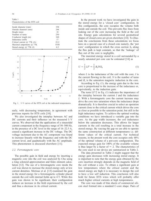
Fig. 1.<br />
I–V curves of the HTS coil <strong>at</strong> the indic<strong>at</strong>ed temper<strong>at</strong>ures.<br />
early, with decreasing temper<strong>at</strong>ure, in agreement with<br />
previous reports for HTS coils [10].<br />
We also investig<strong>at</strong>ed the interplay between AC and<br />
DC currents and their influence on the measured I–V<br />
curves. We observed th<strong>at</strong> the applic<strong>at</strong>ion of a sinusoidal<br />
current component in the frequency range of 50–500 Hz,<br />
in the presence of a DC level in the range of 16–22.5 A,<br />
caused a significant increase in the DC voltage. The DC<br />
voltage increment due to the AC component was found<br />
to increase linearly with the frequency and with the DC<br />
current level, and quadr<strong>at</strong>ically with the AC amplitude.<br />
This phenomenon is discussed elsewhere [11].<br />
2.2. Ferro<strong>magnetic</strong> core<br />
The possible gain in field and <strong>energy</strong> by inserting a<br />
<strong>magnetic</strong> core into the coil was analyzed by Cha using<br />
a long solenoid approxim<strong>at</strong>ion and finite element calcul<strong>at</strong>ion<br />
[12]. The use of a ferro<strong>magnetic</strong> core inside the<br />
coil was shown to increase the stored <strong>energy</strong> only <strong>at</strong> low<br />
current densities. Morisue et al. [13] examined the gain<br />
in the stored <strong>energy</strong> for a ferro<strong>magnetic</strong> cylinder placed<br />
outside the coil with internal fields up to 4 T. While this<br />
gain was shown to be significant, their configur<strong>at</strong>ion<br />
induces an increase in the field experienced by the coil<br />
and thus a decrease in its critical current.<br />
where L is the inductance of the coil with the core, I is<br />
the current flowing in the coil, N is the number of turns<br />
and B s is the s<strong>at</strong>ur<strong>at</strong>ion <strong>magnetic</strong> induction in the core.<br />
According to Eq. (1), the <strong>energy</strong> gain due to the iron<br />
core is proportional to the increase of the inductance or,<br />
equivalently, to the induction gain.<br />
The term LI 2 /2 in Eq. (1) indic<strong>at</strong>es the importance of<br />
the interplay between the current I and the inductance<br />
L. With a ferro<strong>magnetic</strong> core the current increase may<br />
drive the core into s<strong>at</strong>ur<strong>at</strong>ion where the inductance drops<br />
dram<strong>at</strong>ically. It is therefore crucial to select an oper<strong>at</strong>ion<br />
current close to the critical current which drives the core<br />
as close as possible to the s<strong>at</strong>ur<strong>at</strong>ion point, but still in the<br />
high inductance regime. To achieve the optimal working<br />
conditions we have introduced a variable gap into the<br />
core. As the gap width increases, the coil inductance<br />
below the s<strong>at</strong>ur<strong>at</strong>ion decreases. This allows for larger<br />
currents in the coil resulting in a total increase in the<br />
stored <strong>energy</strong>. By varying the gap we are able to oper<strong>at</strong>e<br />
the same construction <strong>at</strong> different temper<strong>at</strong>ures i.e. different<br />
values of the critical current. For technical<br />
reasons, in the present work the core occupies only 40%<br />
of the optimal volume of a pot-core configur<strong>at</strong>ion. The<br />
expected <strong>energy</strong> gain for 100% of the available volume<br />
is thus larger by a factor of 2. The characteristics of<br />
the core used in our <strong>device</strong> are summarized in Table 2.<br />
The d<strong>at</strong>a presented in Table 2 might suggest th<strong>at</strong> the<br />
<strong>energy</strong> gain decreases with increasing stored <strong>energy</strong>. It<br />
is important to note th<strong>at</strong> the <strong>energy</strong> gain obtained by the<br />
core insertion strongly depends on the <strong>magnetic</strong> field of<br />
the coil without a core. To obtain a significant gain <strong>at</strong><br />
low temper<strong>at</strong>ures where the critical current and the<br />
stored <strong>energy</strong> are high it is necessary to design the coil<br />
to have a low self induction. This conclusion will also<br />
hold for future HTS wires which will probably offer<br />
much higher critical currents <strong>at</strong> high temper<strong>at</strong>ures.<br />
The core was made of thin sheets of commercial silicon<br />
steel formed into a standard C-core shape. Pairs of