Superconducting magnetic energy storage device operating at liquid ...
Superconducting magnetic energy storage device operating at liquid ...
Superconducting magnetic energy storage device operating at liquid ...

You also want an ePaper? Increase the reach of your titles
YUMPU automatically turns print PDFs into web optimized ePapers that Google loves.
A. Friedman et al. /Cryogenics 39 (1999) 53–58<br />
55<br />
Table 2<br />
Parameters of the core<br />
52K 64K 77K<br />
Air gap (mm) 13.3 9 4.1<br />
Core cross-section (m 2 ) 0.013 0.013 0.013<br />
Critical current (A) 72 49 22.2<br />
Energy without core (J) 44 20.4 4.2<br />
Energy with core (J) 193 131 59.4<br />
Energy gain E/E 0 4.4 6.4 14.1<br />
Expected gain for 100% volume 9.3 13.6 30<br />
Inductance without core (H) 0.017 0.017 0.017<br />
Inductance with core (H) 0.075 0.11 0.24<br />
Maximum field with core (T) 1.7 1.7 1.7<br />
Maximum field without core (T) 0.39 0.27 0.12<br />
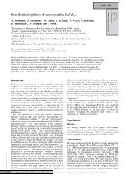
Fig. 2. The coil with the core (for clarity some of the C-cores are<br />
removed).<br />
these C-cores form rings surrounding the coil. PVC spacers<br />
were inserted between the C-cores to form the<br />
appropri<strong>at</strong>e gap <strong>at</strong> the desired <strong>oper<strong>at</strong>ing</strong> temper<strong>at</strong>ure.<br />
Fig. 2 shows a photograph of the coil and the core. For<br />
clarity we removed several of the C-core elements.<br />
2.3. Electric circuit<br />
The electric circuit of our SMES <strong>device</strong> is sketched<br />
in Fig. 3. An important part of the circuit is the converter<br />
which gener<strong>at</strong>es positive and neg<strong>at</strong>ive voltage pulses to<br />
charge and discharge the superconducting coil. Two<br />
capacitor arrays, <strong>at</strong> the charger (C1) and <strong>at</strong> the load (C2),<br />
are used for the conversion of voltage to current in the<br />
coil, and vice versa. The coil is connected to four<br />
switches (Fig. 3), forming an open bridge configur<strong>at</strong>ion,<br />
and protected against overvoltage th<strong>at</strong> might occur during<br />
a fault. The switches are responsible for the different<br />
basic st<strong>at</strong>es of oper<strong>at</strong>ion. When switches 1 and 4 are<br />
closed and 2 and 3 are open, the superconducting coil<br />
is charged from the DC power source. When switches<br />
2 and 3 are closed and 1 and 4 are open, the discharge<br />
st<strong>at</strong>e is obtained. In this st<strong>at</strong>e a current is withdrawn from<br />
the coil and fed into the load capacitor to cre<strong>at</strong>e the load<br />
voltage. When switches 1 and 3 are closed and 2 and 4<br />
are open the coil is in the ‘persistent’ st<strong>at</strong>e and the current<br />
flows in a closed loop within the superconducting<br />
coil. The persistent st<strong>at</strong>e is set as an intermedi<strong>at</strong>e st<strong>at</strong>e<br />
when charge or discharge st<strong>at</strong>es are not required. The<br />
switches settings for the different st<strong>at</strong>es are summarized<br />
in Table 3.<br />
To reduce <strong>energy</strong> losses in the converter, most of its<br />
elements were immersed in <strong>liquid</strong> nitrogen. The resistance<br />
of the switches drops from 7 m <strong>at</strong> room temper<strong>at</strong>ure<br />
to 2 m <strong>at</strong> LN 2 temper<strong>at</strong>ures. As shown in Table 3<br />
and Fig. 3, switch 2 plays the role of a diode. We have<br />
found th<strong>at</strong> MOSFET transistors exhibit low resistance in<br />
comparison with other kinds of electronic switches and<br />
diodes <strong>at</strong> LN 2 temper<strong>at</strong>ures. Two kinds of capacitors<br />
were used as charger and load capacitors. One capacitors<br />
bank, which carries high currents, was immersed in the<br />
Fig. 3.<br />
Electric circuit of the SMES.<br />
Table 3<br />
Switches settings for the various oper<strong>at</strong>ion st<strong>at</strong>es of the SMES<br />
St<strong>at</strong>e S1 S2 S3 S4<br />
Charge Closed Open Open Closed<br />
Persistent Closed Open Closed Open<br />
Discharge Open Closed Closed Open<br />
Through Open Closed Open Closed