Superconducting magnetic energy storage device operating at liquid ...
Superconducting magnetic energy storage device operating at liquid ...
Superconducting magnetic energy storage device operating at liquid ...

You also want an ePaper? Increase the reach of your titles
YUMPU automatically turns print PDFs into web optimized ePapers that Google loves.
A. Friedman et al. /Cryogenics 39 (1999) 53–58<br />
57<br />
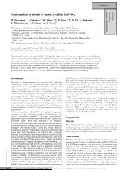
the stored <strong>energy</strong> on the oper<strong>at</strong>ion current becomes<br />
weaker (see Table 2). As a result, the calcul<strong>at</strong>ed figure<br />
of merit (squares in Fig. 5) exhibits a maximum around<br />
50K, upwarding the practical range (between the 3 db<br />
points) to 15–77K, overlapping with the regime of<br />
LN 2 temper<strong>at</strong>ures.<br />
The HTS coil, the core and part of the electric circuit<br />
(marked in a rectangular frame in Fig. 3) are immersed<br />
in LN 2 . While <strong>oper<strong>at</strong>ing</strong>, the he<strong>at</strong> gener<strong>at</strong>ed by the<br />
SMES causes additional losses of 0.1 l/h, which is about<br />
30% of the overall cooling losses in our dewar.<br />
The main sources for the oper<strong>at</strong>ion losses are the<br />
ohmic components in the <strong>device</strong>. We have therefore<br />
selected electric components th<strong>at</strong> are suitable for oper<strong>at</strong>ion<br />
<strong>at</strong> LN 2 temper<strong>at</strong>ures. The losses due to these<br />
components are much lower <strong>at</strong> low temper<strong>at</strong>ures than <strong>at</strong><br />
room temper<strong>at</strong>ure.<br />
The working temper<strong>at</strong>ure was achieved by controlling<br />
the vapor pressure of the LN 2 . The SMES oper<strong>at</strong>ion was<br />
tested between 52K (solid nitrogen) and 77K. Although<br />
pumping adds to the cost of oper<strong>at</strong>ion, it adds flexibility<br />
in choosing the working temper<strong>at</strong>ure, allowing for an<br />
increase in the stored <strong>energy</strong> and power.<br />
To avoid working in solid nitrogen which offers<br />
inferior thermal contact than the <strong>liquid</strong>, we have selected<br />
the oper<strong>at</strong>ion temper<strong>at</strong>ure to be 64K, which is slightly<br />
above the triple point of nitrogen (T 63.2K). This temper<strong>at</strong>ure<br />
is achieved <strong>at</strong> a vapor pressure of about<br />
100 Torr th<strong>at</strong> is accessible by a low power-consuming<br />
rotary vacuum pump. The <strong>liquid</strong> st<strong>at</strong>e of nitrogen<br />
ensures ideal cooling conditions of the coil and other<br />
elements of the electric circuit.<br />
3. Oper<strong>at</strong>ion<br />
Integr<strong>at</strong>ion of the components described above results<br />
in a SMES <strong>device</strong> <strong>oper<strong>at</strong>ing</strong> in the temper<strong>at</strong>ure range<br />
between 64 and 77K with a stored <strong>energy</strong> of up to 130 J<br />
(<strong>at</strong> 64K). This <strong>device</strong> supplies a stable DC voltage to<br />
the load, which does not depend on the power quality<br />
of the input AC line.<br />
For a persistent current of 15 A the losses per second<br />
<strong>at</strong> 77K are, on the average, 0.5% of the stored <strong>energy</strong>.<br />
These losses are mainly a result of the ohmic components<br />
of the circuit. At this current, the intrinsic losses<br />
of the superconducting coil are two orders of magnitude<br />
less than the ohmic losses and are negligible.<br />
Fig. 6 demonstr<strong>at</strong>es the oper<strong>at</strong>ion of the SMES <strong>at</strong><br />
77K. The first 2 s show its oper<strong>at</strong>ion as a converter, with<br />
a load of 6 W. In this mode, <strong>energy</strong> of 50 J is stored in<br />
the coil while pulses of neg<strong>at</strong>ive and positive voltage,<br />
shown in the lower left part of the figure, charge and<br />
discharge the coil. The need for a charge or discharge<br />
pulse is determined by the control circuit which probes<br />
the coil current and the load voltage. Simultaneous<br />
Fig. 6. Oper<strong>at</strong>ion of the SMES <strong>device</strong> <strong>at</strong> 77K as a function of time.<br />
The upper curve is a record of the load voltage. Charge (neg<strong>at</strong>ive) and<br />
discharge (positive) pulses are shown in the lower part of the figure.<br />
The middle curve records the coil current which is proportional to the<br />
square root of the stored <strong>energy</strong>.<br />
appearance of charge and discharge pulses are apparent<br />
in the figure. After approxim<strong>at</strong>ely 2 s the SMES was disconnected<br />
from the AC line in order to simul<strong>at</strong>e a power<br />
failure. Fig. 6 shows th<strong>at</strong> while the charge pulses are<br />
stopped, the discharge pulses continue so th<strong>at</strong> the voltage<br />
across the load (the upper curve in the figure) is kept<br />
constant. As the <strong>energy</strong> stored in the coil decreases<br />
(middle curve), the frequency of the discharge pulses<br />
increase because each pulse converts less <strong>energy</strong>. When<br />
the stored <strong>energy</strong> reaches a predefined lower limit (in<br />
our case it is 4% of the stored <strong>energy</strong>), the SMES oper<strong>at</strong>ion<br />
is stopped and the output voltage drops to zero. It<br />
is important to note th<strong>at</strong> throughout all the time of SMES<br />
oper<strong>at</strong>ion the output voltage remains constant. The ripple<br />
seen in the voltage curve (upper curve) is a user defined<br />
value and may be set to a value as low as required. For<br />
a lower ripple value the discharging pulses will become<br />
narrower but more frequent. In this case losses in the<br />
SMES <strong>device</strong> grow as a result of the increase in the r<strong>at</strong>e<br />
of switching oper<strong>at</strong>ions.<br />
4. Summary<br />
We have designed, built and tested a prototype of<br />
SMES <strong>oper<strong>at</strong>ing</strong> in the temper<strong>at</strong>ure range between 64<br />
and 77K using <strong>liquid</strong> nitrogen cooling. This method of<br />
cooling offers a good thermal contact between the coolant<br />
and the <strong>device</strong>, it provides good thermal stability and<br />
homogeneity, and therefore is suitable for large scale<br />
applic<strong>at</strong>ions.<br />
We have used a ferro<strong>magnetic</strong> core to increase the<br />
stored <strong>energy</strong> in our SMES. A variable gap was intro-