Steel Joist Manual
Steel Joist Manual
Steel Joist Manual

You also want an ePaper? Increase the reach of your titles
YUMPU automatically turns print PDFs into web optimized ePapers that Google loves.
Contact the Vulcraft Sales Corporation Office nearest you:<br />
Albuquerque, NM Area<br />
Ph. (505) 892-0707<br />
Fax (505) 892-2727<br />
Atlanta, GA Area<br />
Ph. (770) 338-9363<br />
Fax (770) 338-9757<br />
Baltimore, MD Area<br />
Ph. (410) 998-0800<br />
Fax (410) 998-0801<br />
Birmingham, AL Area<br />
Ph. (205) 380-0070<br />
Fax (205) 380-0077<br />
Chicago, IL Area<br />
Ph. (630) 887-1400<br />
Fax (630) 887-1477<br />
Columbia, SC Area<br />
Ph. (803) 732-5557<br />
Fax (803) 732-5551<br />
Dallas, TX Area<br />
Ph. (214) 340-1883<br />
Fax (214) 340-5897<br />
Danbury, CT Area<br />
Ph. (203) 791-1227<br />
Fax (203) 791-8657<br />
Dayton, OH Area<br />
Ph. (937) 390-2300<br />
Fax (937) 390-2333<br />
Denver, CO Area<br />
Ph. (303) 757-6323<br />
Fax (303) 757-6324<br />
Des Moines, IA Area<br />
Ph. (515) 270-2500<br />
Fax (515) 270-8849<br />
Detroit, MI Area<br />
Ph. (248) 486-6166<br />
Fax (248) 486-6169<br />
Fargo, ND Area<br />
Ph. (701) 235-6605<br />
Fax (701) 234-1966<br />
Ft. Wayne/S. Bend, IN Area<br />
Ph. (260) 337-1800<br />
Fax (260) 337-1801<br />
Grand Rapids, MI Area<br />
Ph. (616) 949-2106<br />
Fax (616) 949-6694<br />
Greensboro, NC Area<br />
Ph. (336) 294-9544<br />
Fax (336) 294-7636<br />
Greenville, NC Area<br />
Ph. (252) 493-0333<br />
Fax (252) 493-0555<br />
Houston, TX Area<br />
Ph. (281) 477-6700<br />
Fax (281) 477-6701<br />
Indianapolis, IN Area<br />
Ph. (317) 576-5399<br />
Fax (317) 576-5395<br />
Jackson, MS Area<br />
Ph. (601) 936-6215<br />
Fax (601) 936-6216<br />
Jacksonville, FL Area<br />
Ph. (904) 880-1150<br />
Fax (904) 880-1151<br />
Kansas City, KS Area<br />
Ph. (913) 341-9299<br />
Fax (913) 341-5764<br />
Knoxville, TN Area<br />
Ph. (865) 690-6388<br />
Fax (865) 690-6389<br />
Lexington, KY Area<br />
Ph. (859) 271-2591<br />
Fax (859) 271-2580<br />
Little Rock, AR Area<br />
Ph. (501) 758-6424<br />
Fax (501) 758-6427<br />
Los Angeles, CA Area<br />
Ph. (714) 957-5713<br />
Fax (714) 957-8871<br />
Memphis, TN Area<br />
Ph. (901) 751-2154<br />
Fax (901) 759-1152<br />
Miami, FL Area<br />
Ph. (954) 785-8695<br />
Fax (954) 785-8696<br />
Milwaukee/Green Bay, WI Area<br />
Ph. (262) 251-5666<br />
Fax (262) 251-7065<br />
Minneapolis, MN Area<br />
Ph. (763) 425-4399<br />
Fax (763) 425-6905<br />
Nashua, NH Area<br />
Ph. (603) 894-1146<br />
Fax (603) 894-1149<br />
Nashville, TN Area<br />
Ph. (615) 889-6673<br />
Fax (615) 889-0818<br />
North Alabama Area<br />
Ph. (256) 845-2460<br />
Fax (256) 845-2823<br />
Oklahoma City, OK Area<br />
Ph. (405) 715-2844<br />
Fax (405) 715-5855<br />
Philadelphia, PA Area<br />
Ph. (610) 292-8009<br />
Fax (610) 292-8155<br />
Phoenix, AZ Area<br />
Ph. (480) 730-3012<br />
Fax (480) 730-2824<br />
Pittsburgh, PA Area<br />
Ph. (724) 695-8200<br />
Fax (724) 695-8628<br />
Richmond, VA Area<br />
Ph. (804) 379-3704<br />
Fax (804) 379-3709<br />
Rochester, NY Area<br />
Ph. (585) 394-8400<br />
Fax (585) 394-8488<br />
Salt Lake City, UT Area<br />
Ph. (801) 355-0431<br />
Fax (801) 621-0927<br />
San Antonio, TX Area<br />
Ph. (210) 655-9070<br />
Fax (210) 655-9504<br />
San Francisco, CA Area<br />
Ph. (925) 229-1020<br />
Fax (925) 229-2469<br />
Seattle, WA Area<br />
Ph. (425) 957-7252<br />
Fax (425) 957-7295<br />
St. Louis, MO Area<br />
Ph. (314) 894-6076<br />
Fax (314) 894-9173<br />
Tampa, FL Area<br />
Ph. (813) 621-0684<br />
Fax (813) 626-4955<br />
Youngstown, OH Area<br />
Ph. (330) 726-8833<br />
Fax (330) 726-0694<br />
To view a map of the Vulcraft Sales Corporation Office nearest you,<br />
logon to our website at www.vulcraft.com.
TABLE OF CONTENTS<br />
VULCRAFT DESIGN NOTICE ...................................................................................... 4<br />
GENERAL INFORMATION............................................................................................ 5<br />
A. <strong>Joist</strong> Design Commentary<br />
1. Vibration<br />
2. Deflection<br />
3. How to Specify Concentrated &Other Non-Uniform Loads on <strong>Steel</strong> <strong>Joist</strong>s<br />
4. Recycled Content – LEED Program<br />
K AND KCS SERIES...................................................................................................... 9<br />
A. General Information<br />
B. K Series Specifications<br />
C. K Series LRFD and ASD Load Tables<br />
D. KCS Series LRFD and ASD Load Tables<br />
ACCESSORIES AND DETAILS..................................................................................... 35<br />
A. K Series <strong>Joist</strong> Substitutes<br />
B. 2.5K Series and Loose Outriggers<br />
C. K Series Top Chord Extensions and Extended Ends<br />
D. K Series Extensions LRFD and ASD Load Tables<br />
E. K Series Open Web <strong>Steel</strong> <strong>Joist</strong>s<br />
F. LH and DLH Series Details<br />
LH AND DLH SERIES ................................................................................................... 49<br />
A. General Information<br />
B. LH and DLH Series Specifications<br />
C. LH Series LRFD and ASD Load Tables<br />
D. DLH Series LRFD and ASD Load Tables<br />
SLH SERIES .................................................................................................................. 73<br />
A. General Information<br />
B. SLH Details<br />
C. SLH-Load Tables<br />
D. SLH-Specifications<br />
JOIST GIRDERS............................................................................................................ 89<br />
A. General Information<br />
B. <strong>Joist</strong> Girder Details<br />
C. Bottom Chord Brace Tables<br />
D. <strong>Joist</strong> Girders in Moment Resistant Frames<br />
E. <strong>Joist</strong> Girder Specifications<br />
F. <strong>Joist</strong> Girder LRFD and ASD Weight Tables<br />
FIRE RESISTANCE RATINGS WITH STEEL JOIST AND JOIST GIRDERS ............... 113<br />
ECONOMICAL JOIST GUIDE....................................................................................... 123<br />
RECOMMENDED CODE OF STANDARD PRACTICE ................................................ 135<br />
GLOSSARY.................................................................................................................... 144<br />
OSHA SAFETY STANDARDS FOR STEEL ERECTION .............................................. 148<br />
PUBLICATIONS............................................................................................................. 157<br />
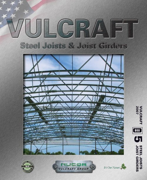
FRONT COVER PICTURE:<br />
The Prairie School - Racine, Wisconsin<br />
This 68,000 sq. ft facility included a new locker room, fitness and weight training areas, a field house, and a track. The primary<br />
framing system consisted of a braced, compound-curved steel frame supporting long span barrel vaulted steel joists at the<br />
roof with precast plank supported on a steel frame and load bearing masonry walls at the floor. The structure was supported<br />
on conventional spread footings. The building featured large areas of clerestory glazing and curvilinear form.<br />
1
ALABAMA<br />
7205 Gault Avenue N.<br />
Fort Payne, Alabama 35967<br />
P.O. Box 680169<br />
Fort Payne, Alabama 35968<br />
(256) 845-2460 • Fax: (256) 845-2823<br />
email: sales@vulcraft-al.com<br />
ISO 9001 Certified<br />
ISO 14001 Certified<br />
<strong>Joist</strong>s & Deck<br />
INDIANA<br />
6610 County Road 60<br />
P.O. Box 1000<br />
St.Joe, Indiana 46785<br />
(260) 337-1800 • Fax: (260) 337-1801<br />
email: sales@vulcraft-in.com<br />
ISO 9001 Certified<br />
ISO 14001 Certified<br />
<strong>Joist</strong>s & Deck<br />
NEBRASKA<br />
1601 West Omaha Avenue<br />
Norfolk, Nebraska 68701<br />
P.O. Box 59<br />
Norfolk, Nebraska 68702<br />
(402) 644-8500 • Fax: (402) 644-8528<br />
email: sales@vulcraft-ne.com<br />
ISO 9001 Certified<br />
ISO 14001 Certified<br />
<strong>Joist</strong>s & Deck<br />
NEW YORK<br />
5362 Railroad Street<br />
P.O. Box 280<br />
Chemung, New York 14825<br />
(607) 529-9000 • Fax: (607) 529-9001<br />
email: sales@vulcraft-ny.com<br />
ISO 9001 Certified<br />
ISO 14001 Certified<br />
<strong>Joist</strong>s & Deck<br />
2
SOUTH CAROLINA<br />
1501 West Darlington Street<br />
P.O. Box 100520<br />
Florence, South Carolina 29501<br />
(843) 662-0381 • Fax: (843) 662-3132<br />
email: sales@vulcraft-sc.com<br />
ISO 9001 Certified<br />
ISO 14001 Certified<br />
<strong>Joist</strong>s & Deck<br />
TEXAS<br />
287 North Main Extension<br />
P.O. Box 186<br />
Grapeland, Texas 75844<br />
(936) 687-4665 • Fax: (936) 687-4290<br />
email: sales@vulcraft-tx.com<br />
ISO 9001 Certified<br />
ISO 14001 Certified<br />
<strong>Joist</strong>s & Deck<br />
UTAH<br />
1875 West Highway 13 South<br />
P.O. Box 637<br />
Brigham City, Utah 84302<br />
(435) 734-9433 • Fax: (435) 723-5423<br />
email: sales@vulcraft-ut.com<br />
ISO 9001 Certified<br />
ISO 14001 Certified<br />
<strong>Joist</strong>s<br />
3
A WORD ABOUT QUALITY<br />
In manufacturing steel joists, there can be no compromise<br />
on quality. Your business depends on it. Our reputation<br />
and success depends on it. As the largest<br />
manufacturer of steel joists in the United States, a lot of<br />
buildings and a lot of people depend on Vulcraft for consistently<br />
high standards of quality that are demonstrated<br />
in reliable performance.<br />
In the manufacturing of steel joists and joist girders,<br />
Vulcraft uses high quality steel. Welding to exact specifications<br />
is the key to making structurally sound joists<br />
— and the most critical step in the entire process. This<br />
being the case, all Vulcraft welders are qualified to<br />
American Welding Society standards. All welds are in<br />
accordance with the <strong>Steel</strong> <strong>Joist</strong> Institute’s welding criteria<br />
and all Vulcraft joists are manufactured to meet the<br />
required design loads of the specifying professional.<br />
To further insure the precision and quality of every<br />
weld, every Vulcraft quality assurance inspector is also<br />
certified to these same high standards. Furthermore<br />
Vulcraft’s quality assurance supervisors report directly<br />
to the engineering manager. Vulcraft also employs an<br />
ongoing program of mechanical testing that includes<br />
full scale load tests at every facility.<br />
As the leading manufacturer of steel joists and joist<br />
girders in the United States, Vulcraft’s reputation depends<br />
on successfully managed quality control programs.<br />
That’s why quality is important at Vulcraft. You<br />
have our word on it.<br />
NOTICE<br />
Vulcraft, a Division of Nucor Corporation, has provided<br />
this catalog for use by engineers and architects in designing<br />
and using Vulcraft open web joists and open<br />
web girders. It includes all products available at the<br />
time of printing. Vulcraft reserves the right to change,<br />
revise or withdraw any Products or procedures without<br />
notice.<br />
The information presented in this catalog has been<br />
prepared in accordance with recognized engineering<br />
principles and is for general information only. While it<br />
is believed to be accurate, this information should not<br />
be used or relied upon for any specific application without<br />
competent professional examination and verification<br />
of its accuracy, suitability and applicability by an<br />
engineer, architect or other licensed professional.<br />
Vulcraft is a manufacturer of open web steel joists, joist<br />
girders, floor deck and roof deck. Vulcraft employs a<br />
staff of engineers for the design, manufacture and<br />
marketing of its products. Vulcraft does not accept the<br />
responsibility as the design professional of record for<br />
any structure. Vulcraft accepts the delegation of the<br />
engineering responsibility only for the products it manufactures,<br />
provided the application and applicable<br />
loading for these products are specified by the design<br />
professional of record. Vulcraft provides engineering<br />
for the design of its products and does not displace the<br />
need on any project for a design professional of<br />
record.<br />
4
JOIST DESIGN COMMENTARY<br />
FLOOR VIBRATION<br />
Floor vibration occurs, in varying degrees, in all types<br />
of building construction. Unlike steady state vibration,<br />
which can be isolated, vibration due to human impact<br />
is inconsistent in amplitude and frequency and therefore,<br />
more difficult to control.<br />
The <strong>Steel</strong> <strong>Joist</strong> Institute and Nucor Research and Development<br />
have studied this phenomenon for many<br />
years. Laboratory research has been performed and<br />
numerous buildings, exhibiting both good and bad<br />
characteristics, were tested using seismic recording<br />
instruments. SJI Technical Digest #5 (1988) and AISC<br />
/ CISC <strong>Steel</strong> Design Guide 11 (1997) discuss in detail<br />
methods for calculating vibrational properties for joist<br />
supported floors.<br />
The vast majority of structures, including those utilizing<br />
steel joists, do not exhibit floor vibrations severe<br />
enough to be considered objectionable. However,<br />
human sensitivity to vibratory motion varies, and a satisfactory<br />
framing solution is dependent upon the sound<br />
judgment of qualified structural engineers.<br />
DEFINITIONS<br />
Floor vibration is measured in terms of acceleration<br />
amplitude, displacement amplitude, and frequency.<br />
These factors are not objectionable to all people at the<br />
same level since human sensitivity varies.<br />
Acceleration amplitude is the maximum acceleration<br />
caused by a force excitation.<br />
Displacement amplitude is defined as the magnitude<br />
or total distance traveled by each oscillation of the<br />
vibration.<br />
Frequency is the term used to describe the speed of<br />
the oscillations and is expressed in cycles per second<br />
or Hz.<br />
Acceleration is the only vibration factor which humans<br />
can sense.<br />
Damping is defined as the rate of decay of amplitude.<br />
The following observations, which were determined<br />
from research data to be beneficial in reducing vibration<br />
levels, are recommended only as a guide.<br />
OPEN FLOOR AREAS are most subject to vibrational<br />
problems. Modern “electronic offices” tend to have<br />
lower live loading and damping, and hence can potentially<br />
be more prone to floor vibration. Partitions, file<br />
cabinets, book stacks, heavy furnishings and even<br />
crowds of people provide additional damping and minimize<br />
complaints.<br />
THICKER FLOOR SLABS are an economical solution<br />
to floor vibration. Additional thickness increases floor<br />
system stiffness transverse to the joists, thus reducing<br />
the vibration. The additional mass of the system will<br />
reduce the objectionable vibration.<br />
WIDER JOIST SPACINGS improve vibrational characteristics<br />
only when combined with thicker floor slabs.<br />
The resulting increase in joist size does not contribute<br />
significantly to the composite section. When used with<br />
a thicker slab, greater resistance to vibration can be<br />
achieved, and, since fewer pieces must be installed,<br />
may be more economical.<br />
PARTITIONS introduce damping and usually eliminate<br />
vibration problems. They will be effective either above<br />
or below a floor as long as they are connected to the<br />
floor. Partitions below a joist supported floor ideally<br />
should be in direct contact with the steel deck. If partitions<br />
below a joist supported floor are in direct contact<br />
with the joists, the joist bottom chord and webs must be<br />
designed for such intermediate support conditions.<br />
SUPPORT FRAMING BEAMS sometimes contribute<br />
to floor vibration. The natural frequency and amplitude<br />
for both the joist and supporting joist girders or hotrolled<br />
girders need to be calculated. In this manner the<br />
resulting system acceleration or displacement and frequency<br />
can be determined from which the performance<br />
of the system can be predicted.<br />
INCREASING JOIST STIFFNESS above that which is<br />
required by live load deflection may be beneficial. A<br />
higher frequency floor is generally a better floor for<br />
most applications. Increasing the stiffness of the steel<br />
joists themselves results in increasing the frequency<br />
and slightly decreasing the acceleration or displacement<br />
of the floor vibration.<br />
BRIDGING of all standard types provide equal floor<br />
vibrational characteristics.<br />
LONGER FLOOR SPANS have many advantages<br />
over shorter spans, both in construction cost and in<br />
vibrational response. Floor spans over 40 feet with a<br />
2-1/2" thick concrete slab give a vibrational frequency<br />
in the 3 - 5 cycles per second range. There are many<br />
long spanning joist supported floors that perform satisfactorily.<br />
PC-based software to evaluate vibration of joist supported<br />
floor systems is available from the<br />
STEEL JOIST INSTITUTE<br />
3127 Mr. Joe White Avenue<br />
Myrtle Beach, SC 29577<br />
phone (843) 626-1995<br />
and<br />
STRUCTURAL ENGINEERS, INC.<br />
537 Wisteria Drive<br />
Radford, VA 24141<br />
phone (540) 731-3330<br />
CONCLUSIONS:<br />
Partitions eliminate vibration problems. When a floor<br />
area cannot have partitions, increasing the slab thickness<br />
and/or increasing the joist stiffness are the most<br />
economical and effective ways to reduce objectionable<br />
vibrations.<br />
For more information refer to <strong>Steel</strong> <strong>Joist</strong> Institute Technical Digest No. 5 "Vibration<br />
of <strong>Steel</strong> <strong>Joist</strong>-Concrete Slab Floors", and the AISC / CISC <strong>Steel</strong> Design<br />
Guide 11 “Floor Vibrations Due to Human Activity”.<br />
5
JOIST DESIGN COMMENTARY<br />
DEFLECTION OF STEEL JOISTS<br />
The deflection of a steel joist when loaded with a<br />
uniformly-distributed load depends upon the following<br />
factors:<br />
w= uniformly-distributed load carried by the joist (plf)<br />
L= (span of the joist -.33)(ft.)<br />
E= modulus of elasticity of steel (29,000,000 psi)<br />
I= 26.767 WLL (L3) (10 -6 ) where WLL=red figure in load<br />
table<br />
Tests have shown that deflection at mid-span may<br />
be determined with reasonable accuracy using the<br />
following formula:<br />
Deflection (inches)=<br />
1.15x5wL 4 (12 3 ) =<br />
384El<br />
25.88wL 4<br />
El<br />
Example: Determine the approximate total load deflection<br />
of a 24K8 for the following conditions:<br />
W=280 plf L=40.0 ft<br />
W LL = 161 plf E=29,000,000 psi<br />
I=26.767(161) (40-.33) 3 (10 -6 )= 269.0 in. 4<br />
Deflection=<br />
25.88(280)(40-.33) 4 =2.30 in.<br />
29,000,000(269)<br />
HOW TO SPECIFY JOISTS FOR CONCENTRATED<br />
LOADS ON STEEL JOISTS<br />
When specifying joists for concentrated loads, the<br />
specifying professional should first attempt to specify a<br />
larger standard joist or a KCS series joist. The joist<br />
specified must have adequate moment and shear<br />
resistance throughout the length of the joist.<br />
The shear resistance of K or LH series joists varies<br />
throughout the length of the joist. The shear capacity<br />
of the joist must be checked at every location by use<br />
of a shear diagram showing the allowable shear envelope<br />
created by the uniform design load of the joist<br />
(given in the table), versus the actual shear diagram.<br />
This diagram can be easily drawn with free software<br />
(Vulcraft Assistant Program) available at our web site<br />
www.vulcraft.com. The following diagram is an example<br />
of a 40’ joist with a 180 plf uniform load plus a concentrated<br />
load of 1900 lbs. at 17’ from the left end.<br />
In this case, using the developed 399 plf load, either a<br />
30K10 with an 11% stress reversal, or a standard<br />
26KCS3 could be specified.<br />
Web members have a 5% stress reversal reserve<br />
capacity. If a stress reversal is larger than 5%, clearly<br />
specify the stress reversal with the joists. An “SP” is not<br />
required as long as the stress reversal requirement is<br />
clearly specified.<br />
When a suitable K or LH series joist cannot be specified,<br />
use the required moment and shear to select a<br />
KCS series joist or use double joists to attain the<br />
required capacity. Note that LH series have deeper<br />
standard bearing depths than K or KCS series joists.<br />
In some cases, a standard joist cannot be reasonably<br />
specified. In this case, all uniform, non-uniform (such<br />
as drift loads or varying uniform loads) and concentrated<br />
loads must be given on the drawing or load diagram<br />
with all dimensions given. The drawback of this<br />
method is that the exact dimensions and locations must<br />
be given. Often this information is not available at<br />
the time of joist fabrication.<br />
Regardless of whether K-series, KCS-series or LHseries<br />
joists are specified, it is important to note that<br />
even though sufficient shear and moment capacity are<br />
provided within the special joist, the localized bending<br />
of the chord members due to concentrated loading<br />
between panel points is not considered. The joist<br />
design generally presumes that all concentrated loads<br />
are to be applied at panel points. When this is not the<br />
case, the specifying professional must specify on the<br />
structural drawings of the contract documents that a<br />
field installed member be located at all concentrated<br />
loads not occurring at panel points (see detail C1).<br />
If the magnitude and locations of all loads are provided<br />
on the structural drawings, Vulcraft can design for the<br />
localized chord bending due to the load at the locations<br />
given.<br />
The second alternative is the most economical.<br />
DETAIL C1<br />
VARYING UNIFORM LOADS ON STEEL JOISTS<br />
The selection process of a joist for varying uniform<br />
loads such as drift loads or stepped uniform loads is<br />
essentially the same as that for concentrated loads.<br />
For K-series joists where the uniform load exceeds<br />
550 pounds per lineal foot, the only options are: double<br />
joists or the use of special (SP) joists. Again a load<br />
diagram should be shown on the structural drawings.<br />
6
JOIST DESIGN COMMENTARY<br />
2006 RECYCLED CONTENT OF NUCOR STEEL<br />
PRODUCTS FOR THE L.E.E.D. ® PROGRAM<br />
Nucor Corporation is the nation’s largest recycler, using<br />
almost 21 million tons of scrap steel in 2006 to create<br />
new products. Nucor uses Electric Arc Furnace (EAF)<br />
technology at all of its steel producing facilities. EAFs<br />
use post-consumer scrap steel material for the major<br />
feedstock, unlike blast furnace operations which use<br />
mined iron ore as the major feedstock. Nucor has prepared<br />
the following information to help calculate the recycled<br />
content for products being used with “Green<br />
Building” applications or for projects<br />
in the L.E.E.D. program. Percentages<br />
are approximate and based on<br />
the total weight of the products. Calculations<br />
are based on 2006 scrap<br />
steel delivered and finished materials<br />
produced. Values do not consider<br />
home scrap or scrap<br />
generated onsite. Specific product<br />
information may be available from<br />
facility representatives.<br />
RECYCLED CONTENT - LEED Version 2.2 Credit 4.1 and 4.2<br />
2006 Recycled <strong>Steel</strong> Content of Nucor Products(*)<br />
(% by Total Weight)<br />
Product Group<br />
Average Recycled Content<br />
Nucor Bar Products >99%<br />
Nucor Sheet Products 70%<br />
Total Nucor <strong>Steel</strong> Combined 82.3%<br />
Vulcraft Structural Products >99%<br />
Vulcraft Decking 70%<br />
REGIONAL MATERIALS - LEED Version 2.2 Credit 5.1 and 5.2<br />
Nucor tracks the origin of all scrap shipments to our mills. Nucor can approximate the amount of scrap extracted<br />
from any project site region. Nucor owns steel and steel products manufacturing facilities throughout the US that<br />
are within 500 miles of almost any project site. Please contact your local sales representative if you have questions<br />
about regional materials.<br />
BAR MILL GROUP - Darlington SC, Norfolk NE, Jewett TX, Plymouth UT, Auburn NY,<br />
Birmingham AL, Kankakee IL, Jackson MS, Seattle WA, Marion OH<br />
2006 Approximate Recycled <strong>Steel</strong> Content Of All Nucor Bar Mill Group Products(*)<br />
Facility Total Scrap Total Alloys and Total Post Consumer Total Pre-consumer<br />
<strong>Steel</strong> Use Other Iron Units Recycled Content Recycled Content<br />
All >99%
JOIST DESIGN COMMENTARY<br />
Sheet Mill Group - Crawfordsville IN, Hickman AR, Berkeley SC, Decatur AL<br />
2006 Approximate Recycled <strong>Steel</strong> Content Of Nucor Sheet Mill Group Products(*)<br />
Facility<br />
Total Scrap<br />
<strong>Steel</strong> Used<br />
Total Alloys and<br />
Other Iron Units<br />
Total Post Consumer<br />
Recycled Content<br />
Total Pre-consumer<br />
Recycled Content<br />
Crawfordsville, IN<br />
82%<br />
18%<br />
68%<br />
14%<br />
Hickman, AR<br />
70%<br />
30%<br />
58%<br />
12%<br />
Berkley, SC<br />
56%<br />
44%<br />
46%<br />
10%<br />
Decatur, AL<br />
71%<br />
29%<br />
59%<br />
12%<br />
The Nucor Sheet Mill Group produces hot band, cold rolled, pickled and galvanized products. Nucor Sheet mills<br />
use varying amounts of recycled materials depending on metallurgical product demands and market conditions.<br />
The combined sheet mill total recycled content is approximately 70%.<br />
VULCRAFT GROUP -<br />
Florence SC, Norfolk NE, Brigham City UT, Grapeland TX, St. Joe IN,<br />
Fort Payne AL, Chemung NY<br />
JOISTS - The bar steel for most Vulcraft joists is obtained<br />
from one of the nine Nucor bar mills that use<br />
over 99% scrap steel as their feedstock. A breakdown<br />
of the recycled content of Nucor bar mill products<br />
is detailed above. Vulcraft facilities may receive<br />
steel from sources outside of Nucor that may contain<br />
lower amounts of recycled steel. Specific product information<br />
is available from facility representatives.<br />
DECK – <strong>Steel</strong> for decking produced by Vulcraft facilities<br />
are typically obtained from one of the four Nucor sheet<br />
mills. A breakdown of the recycled content of Nucor<br />
sheet mill products is detailed above. Vulcraft deck<br />
products contain approximately 70% recycled steel.<br />
Additional information is available online through the<br />
<strong>Steel</strong> Recycling Institute at http://www.recycle-steel.org.<br />
(*) Studies from 2005 have shown that the recycled steel used for Nucor products consists of approximately 87% post-consumer scrap.<br />
The remaining 13% typically consists of pre-consumer scrap generated by manufacturing processes for products made<br />
with steel.<br />
All figures shown are based on 2006 figures and may vary from year to year. Please contact your local<br />
sales representative for current average recycled content for Vulcraft products.<br />
8
VULCRAFT K SERIES / GENERAL INFORMATION<br />
ECONOMICAL<br />
HIGH STRENGTH<br />
DESIGN - Vulcraft K Series open web steel<br />
joists are designed in accordance with<br />
specifications of the <strong>Steel</strong> <strong>Joist</strong> Institute.<br />
ACCESSORIES see page 40.<br />
FOR TOP CHORD EXTENSIONS AND<br />
EXTENDED ENDS see page 37.<br />
SJI SPANS TO 60'-0"<br />
PAINT - Vulcraft joists receive a shop-coat of<br />
rust inhibitive primer whose performance<br />
characteristics conform to those of the <strong>Steel</strong><br />
<strong>Joist</strong> Institute specifications 3.3.<br />
SPECIFICATIONS see page 10.<br />
KCS SERIES JOIST see page 29.<br />
MAXIMUM JOIST SPACING FOR HORIZONTAL BRIDGING<br />
BRIDGING MATERIAL SIZE<br />
Round Rod<br />
Equal Leg Angles<br />
SECTION 1/2"DIA 1 x 7/64 1-1/4 x 7/64 1-1/2 x7/64 1-3/4 x 7/64 2x 1/8 2-1/2 x 5/32<br />
NUMBER** (13mm) (25mm x 3mm) (32mm x 3mm) (38mm x 3mm) (45mm x 3mm) (51mm x 3mm) (64mm x 4mm)<br />
r = .13" r = .25" r = .25" r = .30" r = .35" r = .40" r = .50"<br />
1 thru 9 3'-3" 5'-0" 6'-3" 7'-6" 8'-7" 10'-0" 12'-6"<br />
(991mm) (1524mm) (1905mm) (2286mm) (2616mm) (3048mm) (3810mm)<br />
10 3'-0" 4'-8" 6'-3" 7'-6" 8'-7" 10'-0" 12'-6"<br />
(914mm) (1422mm) (1905mm) (2286mm) (2616mm) (3048mm) (3810mm)<br />
11 and 12 2'-7" 4'-0" 5'-8" 7'-6" 8'-7" 10'-0" 12'-6"<br />
(787mm) (1219mm) (1727mm) (2286mm) (2616mm) (3048mm) (3810mm)<br />
*SECTION NUMBER REFERS TO THE LAST DIGITS OF JOIST DESIGNATION, CONNECTION TO JOIST MUST RESIST 700 POUNDS (3114 N)<br />
MAXIMUM JOIST SPACING FOR DIAGONAL BRIDGING<br />
BRIDGING ANGLE SIZE-EQUAL LEG ANGLES<br />
JOIST<br />
DEPTH 1 x 7/64 1 1/4 X7/64 1 1/2 X 7/64 1 3/4 x 7/64<br />
(25mm x 3mm) (32mm x 3mm) (38mm x 3mm) (45mm x 3mm)<br />
r = .20" r = .25" r = .30" r = .35"<br />
12 6'-6" (1981mm) 8'-3" (2514mm) 9'-11" (3022mm) 11'-7" (3530mm)<br />
14 6'-6" (1981mm) 8'-3" (2514mm) 9'-11" (3022mm) 11'-7" (3530mm)<br />
16 6'-6" (1981mm) 8'-2" (2489mm) 9'-10" (2997mm) 11'-6" (3505mm)<br />
18 6'-6" (1981mm) 8'-2" (2489mm) 9'-10" (2997mm) 11'-6" (3505mm)<br />
20 6'-5" (1955mm) 8'-2" (2489mm) 9'-10" (2997mm) 11'-6" (3505mm)<br />
22 6'-4" (1930mm) 8'-1" (2463mm) 9'-10" (2997mm) 11'-6" (3505mm)<br />
24 6'-4" (1930mm) 8'-1" (2463mm) 9'-9" (2971mm) 11'-5" (3479mm)<br />
26 6'-3" (1905mm) 8'-0" (2438mm) 9'-9" (2971mm) 11'-5" (3479mm)<br />
28 6'-2" (1879mm) 8'-0" (2438mm) 9'-8" (2946mm) 11'-5" (3479mm)<br />
30 6'-2" (1879mm) 7'-11" (2413mm) 9'-8" (2946mm) 11'-4" (3454mm)<br />
K-series--all sections numbers use A307 bolt 3/8" (9mm) diameter.<br />
See page 16 for number of rows of bridging required.<br />
BRIDGING FOR STANDING SEAM ROOF<br />
SYSTEMS:<br />
Generally, standing seam roof systems will not<br />
adequately brace the top chords of the joists<br />
with standard SJI bridging. We therefore,<br />
recommend that when a standing seam roof<br />
system is specified, the design professional<br />
specifically state that the joist manufacturer is<br />
to check the bridging requirements and<br />
provide bridging as required to adequately<br />
brace the top chord against lateral movement<br />
under full loading conditions.<br />
UPLIFT BRIDGING:<br />
Where uplift forces due to wind are a design<br />
requirement, these forces must be indicated<br />
on the structural drawings in terms of net uplift<br />
in pounds per square foot or pounds per linear<br />
foot. When these loads are specified, they<br />
must be considered in the design of joists and<br />
bridging. As a minimum, a single line of bottom<br />
chord bridging must be provided near the first<br />
bottom chord panel point, at each end of the<br />
joist, whenever uplift is a design<br />
consideration.*<br />
*See Section 5.11 of the specifications.<br />
9
American National Standard SJI-K–1.1<br />
STANDARD SPECIFICATIONS<br />
FOR OPEN WEB STEEL JOISTS, K-SERIES<br />
Adopted by the <strong>Steel</strong> <strong>Joist</strong> Institute November 4, 1985<br />
Revised to November 10, 2003 - Effective March 01, 2005<br />
SECTION 1.<br />
SCOPE<br />
This specification covers the design, manufacture and use<br />
of Open Web <strong>Steel</strong> <strong>Joist</strong>s, K-Series. Load and Resistance<br />
Factor Design (LRFD) and Allowable Strength Design (ASD)<br />
are included in this specification.<br />
SECTION 2.<br />
DEFINITION<br />
The term “Open Web <strong>Steel</strong> <strong>Joist</strong>s K-Series,” as used herein,<br />
refers to open web, parallel chord, load-carrying members<br />
suitable for the direct support of floors and roof decks in buildings,<br />
utilizing hot-rolled or cold-formed steel, including coldformed<br />
steel whose yield strength* has been attained by cold<br />
working. K-Series <strong>Joist</strong>s shall be designed in accordance<br />
with this specification to support the uniformly distributed<br />
loads given in the Standard Load Tables for Open Web <strong>Steel</strong><br />
<strong>Joist</strong>s, K-Series, attached hereto.<br />
The KCS <strong>Joist</strong> is a K-Series <strong>Joist</strong> which is provided to<br />
address the problem faced by specifying professionals when<br />
trying to select joists to support uniform plus concentrated<br />
loads or other non-uniform loads.<br />
The design of chord sections for K-Series <strong>Joist</strong>s shall be<br />
based on a yield strength of 50 ksi (345 MPa). The design<br />
of web sections for K-Series <strong>Joist</strong>s shall be based on a yield<br />
strength of either 36 ksi (250 MPa) or 50 ksi (345 MPa).<br />
<strong>Steel</strong> used for K-Series <strong>Joist</strong>s chord or web sections shall<br />
have a minimum yield strength determined in accordance<br />
with one of the procedures specified in Section 3.2, which is<br />
equal to the yield strength assumed in the design.<br />
* The term “Yield Strength” as used herein shall designate<br />
the yield level of a material as determined by the<br />
applicable method outlined in paragraph 13.1 “Yield<br />
Point”, and in paragraph 13.2 “Yield Strength”, of<br />
ASTM A370, Standard Test Methods and Definitions<br />
for Mechanical Testing of <strong>Steel</strong> Products, or as specified<br />
in paragraph 3.2 of this specification.<br />
Standard Specifications and Load Tables, Open Web<br />
<strong>Steel</strong> <strong>Joist</strong>s, K-Series,<br />
<strong>Steel</strong> <strong>Joist</strong> Institute - Copyright, 2005<br />
SECTION 3.<br />
MATERIALS<br />
3.1 STEEL<br />
The steel used in the manufacture of chord and web sections<br />
shall conform to one of the following ASTM Specifications:<br />
• Carbon Structural <strong>Steel</strong>, ASTM A36/A36M.<br />
• High-Strength, Low-Alloy Structural <strong>Steel</strong>, ASTM<br />
A242/A242M.<br />
• High-Strength Carbon-Manganese <strong>Steel</strong> of Structural<br />
Quality, ASTM A529/A529M, Grade 50.<br />
• High-Strength Low-Alloy Columbium-Vanadium Structural<br />
<strong>Steel</strong>, ASTM A572/A572M, Grade 42 and 50.<br />
• High-Strength Low-Alloy Structural <strong>Steel</strong> with 50 ksi (345<br />
MPa) Minimum Yield Point to 4 inches (100 mm) Thick,<br />
ASTM A588/A588M.<br />
• <strong>Steel</strong>, Sheet and Strip, High-Strength, Low-Alloy, Hot-<br />
Rolled and Cold-Rolled, with Improved Corrosion Resistance,<br />
ASTM A606.<br />
• <strong>Steel</strong>, Sheet, Cold-Rolled, Carbon, Structural, High-<br />
Strength Low-Alloy and High-Strength Low-Alloy with<br />
Improved Formability, ASTM A1008/A1008M<br />
• <strong>Steel</strong>, Sheet and Strip, Hot-Rolled, Carbon, Structural,<br />
High-Strength Low-Alloy and High-Strength Low-Alloy with<br />
Improved Formability, ASTM A1011/A1011M<br />
or shall be of suitable quality ordered or produced to other than<br />
the listed specifications, provided that such material in the state<br />
used for final assembly and manufacture is weldable and is<br />
proved by tests performed by the producer or manufacturer to<br />
have the properties specified in Section 3.2.<br />
3.2 MECHANICAL PROPERTIES<br />
The yield strength used as a basis for the design stresses<br />
prescribed in Section 4 shall be either 36 ksi (250 MPa) or<br />
50 ksi (345 MPa). Evidence that the steel furnished meets<br />
or exceeds the design yield strength shall, if requested, be<br />
provided in the form of an affidavit or by witnessed or certified<br />
test reports.<br />
For material used without consideration of increase in yield<br />
strength resulting from cold forming, the specimens shall be<br />
taken from as-rolled material. In the case of material, the mechanical<br />
properties of which conform to the requirements of<br />
one of the listed specifications, the test specimens and procedures<br />
shall conform to those of such specifications and to<br />
ASTM A370.<br />
10
OPEN WEB STEEL JOISTS, K-SERIES<br />
In the case of material, the mechanical properties of which<br />
do not conform to the requirements of one of the listed specifications,<br />
the test specimens and procedures shall conform<br />
to the applicable requirements of ASTM A370, and the specimens<br />
shall exhibit a yield strength equal to or exceeding the<br />
design yield strength and an elongation of not less than (a)<br />
20 percent in 2 inches (51 millimeters) for sheet and strip, or<br />
(b) 18 percent in 8 inches (203 millimeters) for plates,<br />
shapes and bars with adjustments for thickness for plates,<br />
shapes and bars as prescribed in ASTM A36/A36M,<br />
A242/A242M, A529/A529M, A572/A572M, A588/A588M,<br />
whichever specification is applicable on the basis of design<br />
yield strength.<br />
The number of tests shall be as prescribed in ASTM A6/A6M<br />
for plates, shapes, and bars; and ASTM A606,<br />
A1008/A1008M and A1011/A1011M for sheet and strip.<br />
If as-formed strength is utilized, the test reports shall show<br />
the results of tests performed on full section specimens in<br />
accordance with the provisions of the AISI North American<br />
Specifications for the Design of Cold-Formed <strong>Steel</strong><br />
Structural Members. They shall also indicate compliance<br />
with these provisions and with the following additional<br />
requirements:<br />
a) The yield strength calculated from the test data shall<br />
equal or exceed the design yield strength.<br />
b) Where tension tests are made for acceptance and control<br />
purposes, the tensile strength shall be at least 6 percent<br />
greater than the yield strength of the section.<br />
c) Where compression tests are used for acceptance and<br />
control purposes, the specimen shall withstand a gross<br />
shortening of 2 percent of its original length without<br />
cracking. The length of the specimen shall be not<br />
greater than 20 times the least radius of gyration.<br />
d) If any test specimen fails to pass the requirements of the<br />
subparagraphs (a), (b), or (c) above, as applicable, two<br />
retests shall be made of specimens from the same lot.<br />
Failure of one of the retest specimens to meet such<br />
requirements shall be the cause for rejection of the lot<br />
represented by the specimens.<br />
3.3 PAINT<br />
The standard shop paint is intended to protect the steel for<br />
only a short period of exposure in ordinary atmospheric conditions<br />
and shall be considered an impermanent and provisional<br />
coating.<br />
When specified, the standard shop paint shall conform to<br />
one of the following:<br />
a) <strong>Steel</strong> Structures Painting Council Specification, SSPC<br />
No. 15.<br />
b) Or, shall be a shop paint which meets the minimum performance<br />
requirements of the above listed specification.<br />
SECTION 4.<br />
DESIGN AND<br />
MANUFACTURE<br />
4.1 METHOD<br />
<strong>Joist</strong>s shall be designed in accordance with these specifications<br />
as simply supported, uniformly loaded trusses supporting a<br />
floor or roof deck so constructed as to brace the top chord of<br />
the joists against lateral buckling. Where any applicable design<br />
feature is not specifically covered herein, the design shall be in<br />
accordance with the following specifications:<br />
a) Where the steel used consists of hot-rolled shapes, bars or<br />
plates, use the American Institute of <strong>Steel</strong> Construction,<br />
Specification for Structural <strong>Steel</strong> Buildings.<br />
b) For members that are cold-formed from sheet or strip steel,<br />
use the American Iron and <strong>Steel</strong> Institute, North American<br />
Specification for the Design of Cold-Formed <strong>Steel</strong><br />
Structural Members.<br />
Design Basis:<br />
Designs shall be made according to the provisions in this Specification<br />
for either Load and Resistance Factor Design (LRFD)<br />
or for Allowable Strength Design (ASD).<br />
Load Combinations:<br />
LRFD:<br />
When load combinations are not specified to the joist manufacturer,<br />
the required stress shall be computed for the factored loads<br />
based on the factors and load combinations as follows:<br />
1.4D<br />
1.2D + 1.6 ( L, or L r , or S, or R )<br />
ASD:<br />
When load combinations are not specified to the joist manufacturer,<br />
the required stress shall be computed based on the load<br />
combinations as follows:<br />
D<br />
D + ( L, or L r , or S, or R )<br />
Where:<br />
D = dead load due to the weight of the structural elements<br />
and the permanent features of the structure<br />
L = live load due to occupancy and movable equipment<br />
L r = roof live load<br />
S = snow load<br />
R = load due to initial rainwater or ice exclusive of the<br />
ponding contribution<br />
When special loads are specified and the specifying professional<br />
does not provide the load combinations, the provisions of ASCE<br />
7, “Minimum Design Loads for Buildings and Other Structures”<br />
shall be used for LRFD and ASD load combinations.<br />
11
OPEN WEB STEEL JOISTS, K-SERIES<br />
4.2 DESIGN AND ALLOWABLE STRESSES<br />
Design Using Load and Resistance Factor Design (LRFD)<br />
<strong>Joist</strong>s shall have their components so proportioned that the<br />
required stresses, f u , shall not exceed φF n where,<br />
f u = required stress ksi (MPa)<br />
F n = nominal stress ksi (MPa)<br />
φ = resistance factor<br />
φF n = design stress<br />
Design Using Allowable Strength Design (ASD)<br />
<strong>Joist</strong>s shall have their components so proportioned that the<br />
required stresses, f, shall not exceed F n / Ω where,<br />
f = required stress ksi (MPa)<br />
F n = nominal stress ksi (MPa)<br />
Ω = safety factor<br />
F n /Ω = allowable stress<br />
Stresses:<br />
(a) Tension: φ t = 0.90 (LRFD) Ω = 1.67 (ASD)<br />
For Chords: F y = 50 ksi (345 MPa)<br />
For Webs: F y = 50 ksi (345 MPa), or F y = 36 ksi (250 MPa)<br />
Design Stress = 0.9F y (LRFD) (4.2-1)<br />
Allowable Stress = 0.6F y (ASD) (4.2-2)<br />
(b) Compression: φ c = 0.90 (LRFD) Ω c = 1.67 (ASD)<br />
For members with<br />
For members with<br />
l<br />
r<br />
≤ 4.71<br />
QF y<br />
F cr = Q 0.658 F e F y (4.2-3)<br />
l<br />
r<br />
> 4.71<br />
F cr = 0.877F e (4.2-4)<br />
For hot-rolled sections, “Q” is the full reduction factor for<br />
slender compression elements.<br />
Design Stress = 0.9F cr (LRFD) (4.2-6)<br />
Allowable Stress = 0.6F cr (ASD) (4.2-7)<br />
In the above equations, l is taken as the distance in inches<br />
(millimeters) between panel points for the chord members<br />
√<br />
( )<br />
√<br />
E<br />
QF y<br />
E<br />
QF y<br />
Where F e = Elastic buckling stress determined in<br />
accordance with Equation 4.2-5.<br />
F e = π (4.2-5)<br />
( 2 E<br />
)<br />
2<br />
l<br />
r<br />
and the appropriate length for web members, and r is the<br />
corresponding least radius of gyration of the member or<br />
any component thereof. E is equal to 29,000 ksi (200,000<br />
MPa).<br />
Use 1.2 l/r x for a crimped, first primary compression web<br />
member when a moment-resistant weld group is not used<br />
for this member; where r x = member radius of gyration in<br />
the plane of the joist.<br />
For cold-formed sections the method of calculating the nominal<br />
column strength is given in the AISI, North American<br />
Specification for the Design of Cold-Formed <strong>Steel</strong> Structural<br />
Members.<br />
(c) Bending: φ b = 0.90 (LRFD) Ω b = 1.67 (ASD)<br />
Bending calculations are to be based on using the elastic<br />
section modulus.<br />
For chords and web members other than solid rounds:<br />
F y = 50 ksi (345 MPa)<br />
Design Stress = 0.9F y (LRFD) (4.2-8)<br />
Allowable Stress = 0.6F y (ASD) (4.2-9)<br />
For web members of solid round cross section:<br />
F y = 50 ksi (345 MPa), or F y = 36 ksi (250 MPa)<br />
Design Stress = 1.45F y (LRFD) (4.2-10)<br />
Allowable Stress = 0.95F y (ASD) (4.2-11)<br />
For bearing plates:<br />
F y = 50 ksi (345 MPa), or F y = 36 ksi (250 MPa)<br />
Design Stress = 1.35F y (LRFD) (4.2-12)<br />
Allowable Stress = 0.90F y (ASD) (4.2-13)<br />
4.3 MAXIMUM SLENDERNESS RATIOS<br />
The slenderness ratio, l/r, where l is as used in Section 4.2<br />
(b) and r is the corresponding least radius of gyration, shall<br />
not exceed the following:<br />
Top chord interior panels . . . . . . . . . . . . . . . . . . . . . . . . . . . 90<br />
Top chord end panels . . . . . . . . . . . . . . . . . . . . . . . . . . . . . . 120<br />
Compression members other than top chord. . . . . . . . . 200<br />
Tension members . . . . . . . . . . . . . . . . . . . . . . . . . . . . . . . . . 240<br />
4.4 MEMBERS<br />
(a) Chords<br />
The bottom chord shall be designed as an axially loaded<br />
tension member.<br />
The radius of gyration of the top chord about its vertical axis<br />
shall not be less than l/145 where l is the spacing in<br />
inches (millimeters) between lines of bridging as specified in<br />
Section 5.4(c).<br />
The top chord shall be considered as stayed laterally by<br />
the floor slab or roof deck when attachments are in accordance<br />
with the requirements of Section 5.8(e) of these<br />
specifications.<br />
12
OPEN WEB STEEL JOISTS, K-SERIES<br />
The top chord shall be designed for only axial compressive<br />
stress when the panel length, l, does not exceed<br />
24 inches (609 mm). When the panel length exceeds<br />
24 inches (609 mm), the top chord shall be designed as<br />
a continuous member subject to combined axial and<br />
bending stresses and shall be so proportioned that:<br />
For LRFD:<br />
at the panel point:<br />
f au + f bu ≤ 0.9F y (4.4-1)<br />
at the mid panel: for ≥ 0.2,<br />
φ c F cr<br />
f au<br />
+ 8<br />
φ c F cr 9<br />
( )<br />
f au<br />
2φ c F cr<br />
for < 0.2,<br />
φ c F cr<br />
1–<br />
f au<br />
≤ 1.0 (4.4-2)<br />
≤ 1.0 (4.4-3)<br />
f au = P u /A = Required compressive stress, ksi (MPa)<br />
P u = Required axial strength using LRFD load<br />
combinations, kips (N)<br />
f bu = M u /S = Required bending stress at the location under<br />
consideration, ksi (MPa)<br />
M u = Required flexural strength using LRFD load<br />
combinations, kip-in. (N-mm)<br />
S = Elastic Section Modulus, in. 3 (mm 3 )<br />
F cr = Nominal axial compressive stress in ksi (MPa)<br />
based on l/ r as defined in Section 4.2(b),<br />
C m = 1 - 0.3 f au /φF e for end panels<br />
C m = 1 - 0.4 f au /φF e for interior panels<br />
F y = Specified minimum yield strength, ksi (MPa)<br />
F e = π<br />
( 2 E<br />
) , ksi (MPa)<br />
2<br />
l<br />
r x<br />
+<br />
1–<br />
f au<br />
C m f bu<br />
( )<br />
f au<br />
C m f bu<br />
( )<br />
f au<br />
φ c F e<br />
φ c F e<br />
Qφ b F y<br />
Qφ b F y<br />
Where l is the panel length, in inches (millimeters), as<br />
defined in Section 4.2(b) and r x is the radius of gyration<br />
about the axis of bending.<br />
Q = Form factor defined in Section 4.2(b)<br />
A = Area of the top chord, in. 2 (mm 2 )<br />
For ASD:<br />
at the panel point:<br />
at the mid panel: for ≥ 0.2,<br />
f a<br />
f a<br />
+ 8<br />
F a 9<br />
( )<br />
f a<br />
2F a<br />
+<br />
f a + f b ≤ 0.6F y (4.4-4)<br />
f a<br />
F a<br />
C m f b<br />
( )<br />
1.67f a<br />
1– QF b<br />
f a<br />
F a<br />
for < 0.2,<br />
≤ 1.0 (4.4-5)<br />
≤ 1.0 (4.4-6)<br />
= P/A = Required compressive stress, ksi (MPa)<br />
P = Required axial strength using ASD load combinations,<br />
kips (N)<br />
f b = M/S = Required bending stress at the location under<br />
consideration, ksi (MPa)<br />
M = Required flexural strength using ASD load<br />
combinations, kip-in. (N-mm)<br />
S = Elastic Section Modulus, in. 3 (mm 3 )<br />
F a = Allowable axial compressive stress based on l/r as<br />
defined in Section 4.2(b), ksi (MPa)<br />
F b = Allowable bending stress; 0.6F y , ksi (MPa)<br />
C m = 1 - 0.50 f a /F e for end panels<br />
C m = 1 - 0.67 f a /F e for interior panels<br />
(b) Web<br />
The vertical shears to be used in the design of the web<br />
members shall be determined from full uniform loading, but<br />
such vertical shears shall be not less than 25 percent of the<br />
end reaction. Due consideration shall be given to the effect<br />
of eccentricity. The effect of combined axial compression<br />
and bending may be investigated using the provisions of<br />
Section 4.4(a), letting C m = 0.4 when bending due to<br />
eccentricity produces reversed curvature.<br />
Interior vertical web members used in modified Warren<br />
type web systems shall be designed to resist the gravity<br />
loads supported by the member plus an additional axial<br />
load of 1/2 of 1.0 percent of the top chord axial force.<br />
(c) Extended Ends<br />
The magnitude and location of the loads to be supported,<br />
deflection requirements, and proper bracing of extended<br />
F e<br />
C m f b<br />
( )<br />
1.67f<br />
1– a<br />
QF b<br />
F e<br />
13
OPEN WEB STEEL JOISTS, K-SERIES<br />
top chords or full depth cantilever ends shall be clearly indicated<br />
on the structural drawings.<br />
4.5 CONNECTIONS<br />
(a) Methods<br />
<strong>Joist</strong> connections and splices shall be made by attaching<br />
the members to one another by arc or resistance welding<br />
or other accredited methods.<br />
(1) Welded Connections<br />
a) Selected welds shall be inspected visually by the<br />
manufacturer. Prior to this inspection, weld slag<br />
shall be removed.<br />
b) Cracks are not acceptable and shall be repaired.<br />
c) Thorough fusion shall exist between weld and base<br />
metal for the required design length of the weld;<br />
such fusion shall be verified by visual inspection.<br />
d) Unfilled weld craters shall not be included in the<br />
design length of the weld.<br />
e) Undercut shall not exceed 1/16 inch (2 millimeters)<br />
for welds oriented parallel to the principal stress.<br />
f) The sum of surface (piping) porosity diameters shall<br />
not exceed 1/16 inch (2 millimeters) in any 1 inch<br />
(25 millimeters) of design weld length.<br />
g) Weld spatter that does not interfere with paint coverage<br />
is acceptable.<br />
(2) Welding Program<br />
Manufacturers shall have a program for establishing<br />
weld procedures and operator qualification, and for<br />
weld sampling and testing. (See Technical Digest #8 -<br />
Welding of Open Web <strong>Steel</strong> <strong>Joist</strong>s.)<br />
(3) Weld Inspection by Outside Agencies (See Section<br />
5.12 of these specifications)<br />
The agency shall arrange for visual inspection to determine<br />
that welds meet the acceptance standards of<br />
Section 4.5(a)(1) above. Ultrasonic, X-Ray, and magnetic<br />
particle testing are inappropriate for joists due to<br />
the configurations of the components and welds.<br />
(b) Strength<br />
(1) Joint Connections - Joint connections shall be capable<br />
of withstanding forces due to an ultimate load equal to<br />
at least 1.35 times the LRFD, or 2.0 times the ASD load<br />
shown in the applicable Standard Load Table.<br />
(2) Shop Splices – Splices may occur at any point in chord<br />
or web members. Members containing a butt weld<br />
splice shall develop an ultimate tensile force of at least<br />
57 ksi (393 MPa) times the full design area of the chord<br />
or web. The term “member” shall be defined as all<br />
component parts comprising the chord or web, at the<br />
point of the splice.<br />
(c) Eccentricity<br />
Members connected at a joint shall have their centroidal<br />
axes meet at a point if practical. Otherwise, due consideration<br />
shall be given to the effect of eccentricity. In no case<br />
shall eccentricity of any web member at a joint exceed 3/4<br />
of the over-all dimension, measured in the plane of the<br />
web, of the largest member connected. The eccentricity of<br />
any web member shall be the perpendicular distance from<br />
the centroidal axis of that web member to the point on the<br />
centroidal axis of the chord which is vertically above or<br />
below the intersection of the centroidal axes of the web<br />
members forming the joint. Ends of joists shall be proportioned<br />
to resist bending produced by eccentricity at the<br />
support.<br />
4.6 CAMBER<br />
<strong>Joist</strong>s shall have approximate camber in accordance with the<br />
following:<br />
TABLE 4.6-1<br />
Top Chord Length Approximate Camber<br />
20'-0" (6096 mm) 1/4" (6 mm)<br />
30'-0" (9144 mm) 3/8" (10 mm)<br />
40'-0" (12192 mm) 5/8" (16 mm)<br />
50'-0" (15240 mm) 1" (25 mm)<br />
60'-0" (18288 mm) 1 1/2" (38 mm)<br />
The specifying professional shall give consideration to coordinating<br />
joist camber with adjacent framing.<br />
4.7 VERIFICATION OF DESIGN AND MANUFACTURE<br />
(a) Design Calculations<br />
Companies manufacturing K-Series <strong>Joist</strong>s shall submit<br />
design data to the <strong>Steel</strong> <strong>Joist</strong> Institute (or an independent<br />
agency approved by the <strong>Steel</strong> <strong>Joist</strong> Institute) for verification<br />
of compliance with the SJI Specifications. Design data<br />
shall be submitted in detail and in the format specified by<br />
the Institute.<br />
(b) Tests of Chord and Web Members<br />
Each manufacturer shall, at the time of design review by<br />
the <strong>Steel</strong> <strong>Joist</strong> Institute or other independent agency,<br />
verify by tests that the design, in accordance with<br />
Sections 4.1 through 4.5 of this specification, will provide<br />
the theoretical strength of critical members. Such tests<br />
shall be evaluated considering the actual yield strength<br />
of the members of the test joists.<br />
Material tests for determining mechanical properties of<br />
component members shall be conducted.<br />
(c) Tests of Joints and Connections<br />
Each manufacturer shall verify by shear tests on representative<br />
joints of typical joists that connections will meet the<br />
provision of Section 4.5(b). Chord and web members may<br />
be reinforced for such tests.<br />
14
OPEN WEB STEEL JOISTS, K-SERIES<br />
(d) In-Plant Inspections<br />
Each manufacturer shall verify their ability to manufacture<br />
K-Series <strong>Joist</strong>s through periodic In-Plant Inspections.<br />
Inspections shall be performed by an independent<br />
agency approved by the <strong>Steel</strong> <strong>Joist</strong> Institute. The frequency,<br />
manner of inspection, and manner of reporting<br />
shall be determined by the <strong>Steel</strong> <strong>Joist</strong> Institute. The<br />
plant inspections are not a guarantee of the quality of<br />
any specific joists; this responsibility lies fully and solely<br />
with the individual manufacturer.<br />
SECTION 5.<br />
APPLICATION<br />
5.1 USAGE<br />
These specifications shall apply to any type of structure where<br />
floors and roofs are to be supported directly by steel joists<br />
installed as hereinafter specified. Where joists are used other<br />
than on simple spans under uniformly distributed loading as<br />
prescribed in Section 4.1, they shall be investigated and modified<br />
if necessary to limit the required stresses to those listed in<br />
Section 4.2.<br />
CAUTION: If a rigid connection of the bottom chord is to be<br />
made to the column or other support, it shall be made only<br />
after the application of the dead loads. The joist is then no<br />
longer simply supported, and the system must be investigated<br />
for continuous frame action by the specifying professional.<br />
The designed detail of a rigid type connection and moment<br />
plates shall be shown on the structural drawings by the specifying<br />
professional. The moment plates shall be furnished by<br />
other than the joist manufacturer.<br />
5.2 SPAN<br />
The span of a joist shall not exceed 24 times its depth.<br />
5.3 END SUPPORTS<br />
(a) Masonry and Concrete<br />
K-Series <strong>Joist</strong>s supported by masonry or concrete are to<br />
bear on steel bearing plates and shall be designed as steel<br />
bearing. Due consideration of the end reactions and all<br />
other vertical or lateral forces shall be taken by the specifying<br />
professional in the design of the steel bearing plate<br />
and the masonry or concrete. The ends of K-Series <strong>Joist</strong>s<br />
shall extend a distance of not less than 4 inches (102 millimeters)<br />
over the masonry or concrete support and be<br />
anchored to the steel bearing plate. The plate shall be<br />
located not more than 1/2 inch (13 millimeters) from the<br />
face of the wall and shall be not less than 6 inches (152 millimeters)<br />
wide perpendicular to the length of the joist. The<br />
plate is to be designed by the specifying professional and<br />
shall be furnished by other than the joist manufacturer.<br />
Where it is deemed necessary to bear less than 4 inches<br />
(102 millimeters) over the masonry or concrete support,<br />
special consideration is to be given to the design of the<br />
steel bearing plate and the masonry or concrete by the<br />
specifying professional. The joists must bear a minimum<br />
of 21/2 inches (64 millimeters) on the steel bearing plate.<br />
(b) <strong>Steel</strong><br />
Due consideration of the end reactions and all other vertical<br />
and lateral forces shall be taken by the specifying<br />
professional in the design of the steel support. The ends<br />
of K-Series <strong>Joist</strong>s shall extend a distance of not less than<br />
2 1/2 inches (64 millimeters) over the steel supports.<br />
5.4 BRIDGING<br />
Top and bottom chord bridging is required and shall consist of<br />
one or both of the following types.<br />
(a) Horizontal<br />
Horizontal bridging shall consist of continuous horizontal<br />
steel members. Attachments to the joist chords shall be<br />
made by welding or mechanical means and shall be capable<br />
of resisting a nominal (unfactored) horizontal force of<br />
not less than 700 pounds (3114 Newtons).<br />
The ratio of unbraced length to least radius of gyration, l/r,<br />
of the bridging member shall not exceed 300, where l is<br />
the distance in inches (millimeters) between attachments<br />
and r is the least radius of gyration of the bridging member.<br />
(b) Diagonal<br />
Diagonal bridging shall consist of cross-bracing with a<br />
l/r ratio of not more than 200, where l is the distance in<br />
inches (millimeters) between connections and r is the least<br />
radius of gyration of the bracing member. Where crossbracing<br />
members are connected at their point of intersection,<br />
the l distance shall be taken as the distance in inches (millimeters)<br />
between connections at the point of intersection<br />
of the bracing members and the connections to the chord of<br />
the joists. Connections to the chords of steel joists shall be<br />
made by positive mechanical means or by welding.<br />
(c) Quantity and Spacing<br />
The number of rows of top chord bridging shall not be less<br />
than as shown in Bridging Tables 5.4-1 and the spacing<br />
shall meet the requirements of Section 4.4(a). The number<br />
of rows of bottom chord bridging, including bridging required<br />
per Section 5.11, shall not be less than the number<br />
of top chord rows. Rows of bottom chord bridging are permitted<br />
to be spaced independently of rows of top chord<br />
bridging. The spacing of rows of bottom chord bridging<br />
shall meet the slenderness requirement of Section 4.3 and<br />
any specified strength requirements.<br />
(d) Bottom Chord Bearing <strong>Joist</strong>s<br />
Where bottom chord bearing joists are utilized, a row of<br />
diagonal bridging shall be provided near the support(s).<br />
This bridging shall be installed and anchored before the<br />
hoisting cable(s) is released.<br />
15
OPEN WEB STEEL JOISTS, K-SERIES<br />
TABLE 5.4-1<br />
NUMBER OF ROWS OF TOP CHORD BRIDGING**<br />
Refer to the K-Series Load Table and Specification Section 6 for required bolted diagonal bridging.<br />
Distances are <strong>Joist</strong> Span lengths in feet - See “Definition of Span” preceding Load Table.<br />
*Section One Two Three Four Five<br />
Number Row Rows Rows Rows Rows<br />
#1 Up thru 16 Over 16 thru 24 Over 24 thru 28<br />
#2 Up thru 17 Over 17 thru 25 Over 25 thru 32<br />
#3 Up thru 18 Over 18 thru 28 Over 28 thru 38 Over 38 thru 40<br />
#4 Up thru 19 Over 19 thru 28 Over 28 thru 38 Over 38 thru 48<br />
#5 Up thru 19 Over 19 thru 29 Over 29 thru 39 Over 39 thru 50 Over 50 thru 52<br />
#6 Up thru 19 Over 19 thru 29 Over 29 thru 39 Over 39 thru 51 Over 51 thru 56<br />
#7 Up thru 20 Over 20 thru 33 Over 33 thru 45 Over 45 thru 58 Over 58 thru 60<br />
#8 Up thru 20 Over 20 thru 33 Over 33 thru 45 Over 45 thru 58 Over 58 thru 60<br />
#9 Up thru 20 Over 20 thru 33 Over 33 thru 46 Over 46 thru 59 Over 59 thru 60<br />
#10 Up thru 20 Over 20 thru 37 Over 37 thru 51 Over 51 thru 60<br />
#11 Up thru 20 Over 20 thru 38 Over 38 thru 53 Over 53 thru 60<br />
#12 Up thru 20 Over 20 thru 39 Over 39 thru 53 Over 53 thru 60<br />
* Last digit(s) of joist designation shown in Load Table<br />
** See Section 5.11 for additional bridging required for uplift design.<br />
16
OPEN WEB STEEL JOISTS, K-SERIES<br />
5.5 INSTALLATION OF BRIDGING<br />
Bridging shall support the top and bottom chords against lateral<br />
movement during the construction period and shall hold the<br />
steel joists in the approximate position as shown on the joist<br />
placement plans.<br />
The ends of all bridging lines terminating at walls or beams<br />
shall be anchored thereto.<br />
5.6 END ANCHORAGE<br />
(a) Masonry and Concrete<br />
Ends of K-Series <strong>Joist</strong>s resting on steel bearing plates<br />
on masonry or structural concrete shall be attached<br />
thereto with a minimum of two 1/8 inch (3 millimeters)<br />
fillet welds 1 inch (25 millimeters) long, or with two 1/2<br />
inch (13 millimeters) ASTM A307 bolts, or the equivalent.<br />
(b) <strong>Steel</strong><br />
Ends of K-Series <strong>Joist</strong>s resting on steel supports shall<br />
be attached thereto with a minimum of two 1/8 inch<br />
(3 millimeters) fillet welds 1 inch (25 millimeters) long, or<br />
with two 1/2 inch (13 millimeters) ASTM A307 bolts, or<br />
the equivalent. When K-Series <strong>Joist</strong>s are used to provide<br />
lateral stability to the supporting member, the final<br />
connection shall be made by welding or as designated<br />
by the specifying professional.<br />
(c) Uplift<br />
Where uplift forces are a design consideration, roof joists<br />
shall be anchored to resist such forces (Refer to Section<br />
5.11 Uplift).<br />
5.7 JOIST SPACING<br />
<strong>Joist</strong>s shall be spaced so that the loading on each joist does not<br />
exceed the design load (LRFD or ASD) for the particular joist<br />
designation and span as shown in the applicable load tables.<br />
5.8 FLOOR AND ROOF DECKS<br />
(a) Material<br />
Floor and roof decks may consist of cast-in-place or precast<br />
concrete or gypsum, formed steel, wood, or other<br />
suitable material capable of supporting the required load<br />
at the specified joist spacing.<br />
(b) Thickness<br />
Cast-in-place slabs shall be not less than 2 inches (51<br />
millimeters) thick.<br />
(c) Centering<br />
Centering for cast-in-place slabs may be ribbed metal lath,<br />
corrugated steel sheets, paper-backed welded wire fabric,<br />
removable centering or any other suitable material capable<br />
of supporting the slab at the designated joist spacing.<br />
Centering shall not cause lateral displacement or damage<br />
to the top chord of joists during installation or removal of<br />
the centering or placing of the concrete.<br />
(d) Bearing<br />
Slabs or decks shall bear uniformly along the top chords<br />
of the joists.<br />
(e) Attachments<br />
The spacing for slab or deck attachments along the joist<br />
top chord shall not exceed 36 inches (914 millimeters),<br />
and shall be capable of resisting a nominal (unfactored)<br />
lateral force of not less than 300 pounds (1335 Newtons),<br />
i.e., 100 plf (1.46 kN/m).<br />
(f) Wood Nailers<br />
Where wood nailers are used, such nailers in conjunction<br />
with deck or slab shall be attached to the top chords of the<br />
joists in conformance with Section 5.8(e).<br />
(g) <strong>Joist</strong> With Standing Seam Roofing<br />
The stiffness and strength of standing-seam roof clips<br />
varies from one manufacturer to another. Therefore,<br />
some roof systems cannot be counted on to provide lateral<br />
stability to the joists which support the roof.<br />
Sufficient stability must be provided to brace the joists<br />
laterally under the full design load. The compression<br />
chord must resist the chord axial design force in the<br />
plane of the joist (i.e., x-x axis buckling) and out of the<br />
plane of the joist (i.e., y-y axis buckling). Out-of-plane<br />
strength may be achieved by adjusting the bridging spacing<br />
and/or increasing the compression chord area, the<br />
joist depth, and the y-axis radius of gyration. The effective<br />
slenderness ratio in the y-direction equals 0.94 L/r y ; where<br />
L is the bridging spacing in inches (millimeters). The<br />
maximum bridging spacing may not exceed that specified<br />
in Section 5.4(c).<br />
Horizontal bridging members attached to the compression<br />
chords and their anchorage’s must be designed for a<br />
compressive axial force of 0.0025nP, where n is the number<br />
of joists between end anchors and P is the chord design<br />
force in kips (Newtons). The attachment force<br />
between the horizontal bridging member and the compression<br />
chord is 0.005P. Horizontal bridging attached to<br />
the tension chords shall be proportioned so that the slenderness<br />
ratio between attachments does not exceed 300.<br />
Diagonal bridging shall be proportioned so that the slenderness<br />
ratio between attachments does not exceed 200.<br />
17
OPEN WEB STEEL JOISTS, K-SERIES<br />
5.9 DEFLECTION<br />
The deflection due to the design nominal live load shall not<br />
exceed the following:<br />
Floors: 1/360 of span.<br />
Roofs: 1/360 of span where a plaster ceiling is attached<br />
or suspended.<br />
1/240 of span for all other cases.<br />
The specifying professional shall give consideration to the<br />
effects of deflection and vibration* in the selection of joists.<br />
* For further reference, refer to <strong>Steel</strong> <strong>Joist</strong> Institute Technical<br />
Digest #5, “Vibration of <strong>Steel</strong> <strong>Joist</strong>-Concrete Slab Floors”<br />
and the Institute’s Computer Vibration Program.<br />
5.10 PONDING*<br />
The ponding investigation shall be performed by the specifying<br />
professional.<br />
* For further reference, refer to <strong>Steel</strong> <strong>Joist</strong> Institute Technical<br />
Digest #3, “Structural Design of <strong>Steel</strong> <strong>Joist</strong> Roofs to Resist<br />
Ponding Loads” and AISC Specifications.<br />
5.11 UPLIFT<br />
Where uplift forces due to wind are a design requirement,<br />
these forces must be indicated on the contract drawings in<br />
terms of NET uplift in pounds per square foot (Pascals). The<br />
contract documents shall indicate if the net uplift is based<br />
upon LRFD or ASD. When these forces are specified, they<br />
must be considered in the design of joists and/or bridging. A<br />
single line of bottom chord bridging must be provided near<br />
the first bottom chord panel points whenever uplift due to<br />
wind forces is a design consideration.*<br />
* For further reference, refer to <strong>Steel</strong> <strong>Joist</strong> Institute Technical<br />
Digest #6, “Structural Design of <strong>Steel</strong> <strong>Joist</strong> Roofs to Resist<br />
Uplift Loads”.<br />
5.12 INSPECTION<br />
<strong>Joist</strong>s shall be inspected by the manufacturer before shipment<br />
to verify compliance of materials and workmanship with the<br />
requirements of these specifications. If the purchaser wishes<br />
an inspection of the steel joists by someone other than the<br />
manufacturer’s own inspectors, they may reserve the right to<br />
do so in their “Invitation to Bid” or the accompanying “Job<br />
Specifications”.<br />
Arrangements shall be made with the manufacturer for such<br />
inspection of the joists at the manufacturing shop by the purchaser’s<br />
inspectors at purchaser’s expense.<br />
5.13 PARALLEL CHORD SLOPED JOISTS<br />
The span of a parallel chord sloped joist shall be defined by<br />
the length along the slope. Minimum depth, load-carrying<br />
capacity, and bridging requirements shall be determined by<br />
the sloped definition of span. The Standard Load Table<br />
capacity shall be the component normal to the joist.<br />
SECTION 6.*<br />
ERECTION STABILITY<br />
AND HANDLING<br />
When it is necessary for the erector to climb on the joists,<br />
extreme caution must be exercised since unbridged joists may<br />
exhibit some degree of instability under the erector’s weight.<br />
(a) Stability Requirements<br />
1) Before an employee is allowed on the steel joist: BOTH<br />
ends of joists at columns (or joists designated as column<br />
joists) shall be attached to its supports. For all other<br />
joists a minimum of one end shall be attached before the<br />
employee is allowed on the joist. The attachment shall be<br />
in accordance with Section 5.6 – End Anchorage.<br />
When a bolted seat connection is used for erection purposes,<br />
as a minimum, the bolts must be snug tightened.<br />
The snug tight condition is defined as the tightness that<br />
exists when all plies of a joint are in firm contact. This<br />
may be attained by a few impacts of an impact wrench<br />
or the full effort of an employee using an ordinary spud<br />
wrench.<br />
2) On steel joists that do not require erection bridging as<br />
shown by the unshaded area of the Load Tables, only<br />
one employee shall be allowed on the steel joist unless<br />
all bridging is installed and anchored.<br />
* For a thorough coverage of this topic, refer to SJI<br />
Technical Digest #9, “Handling and Erection of <strong>Steel</strong><br />
<strong>Joist</strong>s and <strong>Joist</strong> Girders”.<br />
3) Where the span of the steel joist is within the Red shaded<br />
area of the Load Table, the following shall apply:<br />
a) The row of bridging nearest the mid span of the steel<br />
joists shall be bolted diagonal erection bridging; and<br />
b) Hoisting cables shall not be released until this bolted<br />
diagonal erection bridging is installed and anchored,<br />
unless an alternate method of stabilizing the joist has<br />
been provided; and<br />
c) No more than one employee shall be allowed on<br />
these spans until all other bridging is installed and<br />
anchored.<br />
4) When permanent bridging terminus points cannot be<br />
used during erection, additional temporary bridging terminus<br />
points are required to provide stability.<br />
5) In the case of bottom chord bearing joists, the ends of<br />
the joist must be restrained laterally per Section 5.4(d).<br />
6) After the joist is straightened and plumbed, and all bridging<br />
is completely installed and anchored, the ends of the<br />
joists shall be fully connected to the supports in accordance<br />
with Section 5.6 End Anchorage.<br />
18
OPEN WEB STEEL JOISTS, K-SERIES<br />
(b) Landing and Placing Loads<br />
1) Except as stated in paragraphs 6(b)(3) and 6(b)(4) of<br />
this section, no “construction loads” (1) are allowed on<br />
the steel joists until all bridging is installed and anchored,<br />
and all joist bearing ends are attached.<br />
2) During the construction period, loads placed on the<br />
steel joists shall be distributed so as not to exceed the<br />
capacity of the steel joists.<br />
3) The weight of a bundle of joist bridging shall not exceed<br />
a total of 1000 pounds (454 kilograms). The<br />
bundle of joist bridging shall be placed on a minimum<br />
of 3 steel joists that are secured at one end. The edge<br />
of the bridging bundle shall be positioned within 1 foot<br />
(0.30 m) of the secured end.<br />
(1)<br />
See page 150 for definition of “construction load”.<br />
A copy of the OSHA <strong>Steel</strong> Erection Standard<br />
§1926.757, Open Web <strong>Steel</strong> <strong>Joist</strong>s, is included in<br />
Appendix E for reference purposes.<br />
4) No bundle of deck may be placed on steel joists until all<br />
bridging has been installed and anchored and all joist<br />
bearing ends attached, unless the following conditions<br />
are met:<br />
a) The contractor has first determined from a “qualified<br />
person” (2) and documented in a site-specific erection<br />
plan that the structure or portion of the structure<br />
is capable of supporting the load;<br />
b) The bundle of decking is placed on a minimum of 3<br />
steel joists;<br />
c) The joists supporting the bundle of decking are<br />
attached at both ends;<br />
d) At least one row of bridging is installed and<br />
anchored;<br />
e) The total weight of the decking does not exceed<br />
4000 pounds (1816 kilograms); and<br />
f) The edge of the decking shall be placed within 1 foot<br />
(0.30 meters) of the bearing surface of the joist end.<br />
g) The edge of the construction load shall be placed<br />
within 1 foot (0.30 meters) of the bearing surface of<br />
the joist end.<br />
(c) Field Welding<br />
1) All field welding shall be performed in accordance with<br />
the contract documents. Field welding shall not damage<br />
the joists.<br />
2) On cold-formed members whose yield strength has<br />
been attained by cold working, and whose as-formed<br />
strength is used in the design, the total length of weld at<br />
any one point shall not exceed 50 percent of the overall<br />
developed width of the cold-formed section.<br />
(d) Handling<br />
Care shall be exercised at all times to avoid damage to the<br />
joists and accessories.<br />
(e) Fall Arrest Systems<br />
<strong>Steel</strong> joists shall not be used as anchorage points for a fall<br />
arrest system unless written direction to do so is obtained<br />
from a “qualified person” (2) .<br />
(2) See page 150 for OSHA definition of “qualified<br />
person”.<br />
19
OPEN WEB STEEL JOISTS, K-SERIES<br />
DEFINITION OF SPAN<br />
(U. S. Customary Units)<br />
NOTES: 1) DESIGN LENGTH = SPAN - 0.33 FT.<br />
2) BEARING LENGTH FOR STEEL SUPPORTS SHALL NOT<br />
BE LESS THAN 2 1/2 INCHES; FOR MASONRY AND<br />
CONCRETE NOT LESS THAN 4 INCHES.<br />
3) PARALLEL CHORD JOISTS INSTALLED TO A SLOPE<br />
GREATER THAN 1/2 INCH PER FOOT SHALL USE SPAN<br />
DEFINED BY THE LENGTH ALONG THE SLOPE.<br />
20
STANDARD LRFD LOAD TABLE<br />
OPEN WEB STEEL JOISTS, K-SERIES<br />
Based on a 50 ksi Maximum Yield Strength<br />
Adopted by the <strong>Steel</strong> <strong>Joist</strong> Institute May 1, 2000<br />
Revised to November 10, 2003 – Effective March 01, 2005<br />
The black figures in the following table give the TOTAL safe<br />
factored uniformly distributed load-carrying capacities, in<br />
pounds per linear foot, of LRFD K-Series <strong>Steel</strong> <strong>Joist</strong>s. The<br />
weight of factored DEAD loads, including the joists, must be<br />
deducted to determine the factored LIVE load-carrying capacities<br />
of the joists. Sloped parallel-chord joists shall use span as<br />
defined by the length along the slope.<br />
The figures shown in RED in this load table are the unfactored<br />
nominal LIVE loads per linear foot of joist which will produce<br />
an approximate deflection of 1/360 of the span. LIVE loads<br />
which will produce a deflection of 1/240 of the span may be<br />
obtained by multiplying the figures in RED by 1.5. In no case<br />
shall the TOTAL load capacity of the joists be exceeded.<br />
LRFD<br />
The approximate joist weights per linear foot shown in these<br />
tables do not include accessories.<br />
The approximate moment of inertia of the joist, in inches 4 is;<br />
I j = 26.767(W LL )(L 3 )(10 -6 ), where W LL = RED figure in the<br />
Load Table and L = (Span - 0.33) in feet.<br />
For the proper handling of concentrated and/or varying loads,<br />
see Section 6.1 in the Code of Standard Practice for <strong>Steel</strong><br />
<strong>Joist</strong>s and <strong>Joist</strong> Girders.<br />
Where the joist span exceeds the unshaded area of the<br />
Load Table, the row of bridging nearest the mid span shall be<br />
diagonal bridging with bolted connections at the chords and<br />
intersections.<br />
STANDARD LOAD TABLE FOR OPEN WEB STEEL JOISTS, K-SERIES<br />
Based on a 50 ksi Maximum Yield Strength - Loads Shown in Pounds per Linear Foot (plf)<br />
<strong>Joist</strong><br />
Designation<br />
8K1 10K1 12K1 12K3 12K5 14K1 14K3 14K4 14K6 16K2 16K3 16K4 16K5 16K6 16K7 16K9<br />
Depth (in.) 8 10 12 12 12 14 14 14 14 16 16 16 16 16 16 16<br />
Approx. Wt<br />
(lbs./ft.)<br />
Span (ft.)<br />
8<br />
5.1<br />
825<br />
550<br />
5.0 5.0 5.7 7.1 5.2 6.0 6.7 7.7 5.5 6.3 7.0 7.5 8.1 8.6 10.0<br />
9 825<br />
550<br />
10 825 825<br />
480 550<br />
11 798 825<br />
377 542<br />
12 666 825 825 825 825<br />
288 455 550 550 550<br />
13 565 718 825 825 825<br />
225 363 510 510 510<br />
14 486 618 750 825 825 825 825 825 825<br />
179 289 425 463 463 550 550 550 550<br />
15 421 537 651 814 825 766 825 825 825<br />
145 234 344 428 434 475 507 507 507<br />
16 369 469 570 714 825 672 825 825 825 825 825 825 825 825 825 825<br />
119 192 282 351 396 390 467 467 467 550 550 550 550 550 550 550<br />
17 415 504 630 825 592 742 825 825 768 825 825 825 825 825 825<br />
159 234 291 366 324 404 443 443 488 526 526 526 526 526 526<br />
18 369 448 561 760 528 661 795 825 684 762 825 825 825 825 825<br />
134 197 245 317 272 339 397 408 409 456 490 490 490 490 490<br />
19 331 402 502 681 472 592 712 825 612 682 820 825 825 825 825<br />
113 167 207 269 230 287 336 383 347 386 452 455 455 455 455<br />
20 298 361 453 613 426 534 642 787 552 615 739 825 825 825 825<br />
97 142 177 230 197 246 287 347 297 330 386 426 426 426 426<br />
21 327 409 555 385 483 582 712 499 556 670 754 822 825 825<br />
123 153 198 170 212 248 299 255 285 333 373 405 406 406<br />
22 298 373 505 351 439 529 648 454 505 609 687 747 825 825<br />
106 132 172 147 184 215 259 222 247 289 323 351 385 385<br />
23 271 340 462 321 402 483 592 415 462 556 627 682 760 825<br />
93 116 150 128 160 188 226 194 216 252 282 307 339 363<br />
24 249 312 423 294 367 442 543 381 424 510 576 627 697 825<br />
81 101 132 113 141 165 199 170 189 221 248 269 298 346<br />
25 270 339 408 501 351 390 469 529 576 642 771<br />
100 124 145 175 150 167 195 219 238 263 311<br />
26 249 313 376 462 324 360 433 489 532 592 711<br />
88 110 129 156 133 148 173 194 211 233 276<br />
27 231 289 349 427 300 334 402 453 493 549 658<br />
79 98 115 139 119 132 155 173 188 208 246<br />
28 214 270 324 397 279 310 373 421 459 510 612<br />
70 88 103 124 106 118 138 155 168 186 220<br />
29 259 289 348 391 427 475 570<br />
95 106 124 139 151 167 198<br />
30 241 270 324 366 399 444 532<br />
86 96 112 126 137 151 178<br />
31 226 252 304 342 373 415 498<br />
78 87 101 114 124 137 161<br />
32 213 237 285 321 349 388 466<br />
71 79 92 103 112 124 147<br />
21
LRFD<br />
STANDARD LOAD TABLE FOR OPEN WEB STEEL JOISTS, K-SERIES<br />
Based on a 50 ksi Maximum Yield Strength - Loads Shown in Pounds per Linear Foot (plf)<br />
<strong>Joist</strong><br />
Designation<br />
18K3 18K4 18K5 18K6 18K7 18K9 18K10 20K3 20K4 20K5 20K6 20K7 20K9 20K10 22K4 22K5 22K6 22K7 22K9 22K10 22K11<br />
Depth (In.) 18 18 18 18 18 18 18 20 20 20 20 20 20 20 22 22 22 22 22 22 22<br />
Approx. Wt.<br />
(lbs./ft.)<br />
Span (ft.)<br />
6.6 7.2 7.7 8.5 9 10.2 11.7 6.7 7.6 8.2 8.9 9.3 10.8 12.2 8 8.8 9.2 9.7 11.3 12.6 13.8<br />
18 825 825 825 825 825 825 825<br />
550 550 550 550 550 550 550<br />
19 771 825 825 825 825 825 825<br />
494 523 523 523 523 523 523<br />
20 694 825 825 825 825 825 825 775 825 825 825 825 825 825<br />
423 490 490 490 490 490 490 517 550 550 550 550 550 550<br />
21 630 759 825 825 825 825 825 702 825 825 825 825 825 825<br />
364 426 460 460 460 460 460 453 520 520 520 520 520 520<br />
22 573 690 777 825 825 825 825 639 771 825 825 825 825 825 825 825 825 825 825 825 825<br />
316 370 414 438 438 438 438 393 461 490 490 490 490 490 548 548 548 548 548 548 548<br />
23 523 630 709 774 825 825 825 583 703 793 825 825 825 825 777 825 825 825 825 825 825<br />
276 323 362 393 418 418 418 344 402 451 468 468 468 468 491 518 518 518 518 518 518<br />
24 480 577 651 709 789 825 825 535 645 727 792 825 825 825 712 804 825 825 825 825 825<br />
242 284 318 345 382 396 396 302 353 396 430 448 448 448 431 483 495 495 495 495 495<br />
25 441 532 600 652 727 825 825 493 594 669 729 811 825 825 657 739 805 825 825 825 825<br />
214 250 281 305 337 377 377 266 312 350 380 421 426 426 381 427 464 474 474 474 474<br />
26 408 492 553 603 672 807 825 456 549 618 673 750 825 825 606 682 744 825 825 825 825<br />
190 222 249 271 299 354 361 236 277 310 337 373 405 405 338 379 411 454 454 454 454<br />
27 378 454 513 558 622 747 825 421 508 573 624 694 825 825 561 633 688 768 825 825 825<br />
169 198 222 241 267 315 347 211 247 277 301 333 389 389 301 337 367 406 432 432 432<br />
28 351 423 477 519 577 694 822 391 472 532 579 645 775 825 522 588 640 712 825 825 825<br />
151 177 199 216 239 282 331 189 221 248 269 298 353 375 270 302 328 364 413 413 413<br />
29 327 394 444 483 538 646 766 364 439 495 540 601 723 825 486 547 597 664 798 825 825<br />
136 159 179 194 215 254 298 170 199 223 242 268 317 359 242 272 295 327 387 399 399<br />
30 304 367 414 451 502 603 715 340 411 462 504 561 675 799 453 511 556 619 745 825 825<br />
123 144 161 175 194 229 269 153 179 201 218 242 286 336 219 245 266 295 349 385 385<br />
31 285 343 387 421 469 564 669 318 384 433 471 525 631 748 424 478 520 580 697 825 825<br />
111 130 146 158 175 207 243 138 162 182 198 219 259 304 198 222 241 267 316 369 369<br />
32 267 322 363 396 441 529 627 298 360 406 442 492 592 702 397 448 489 544 654 775 823<br />
101 118 132 144 159 188 221 126 147 165 179 199 235 276 180 201 219 242 287 337 355<br />
33 252 303 342 372 414 498 589 280 339 381 415 463 556 660 373 421 459 511 615 729 798<br />
92 108 121 131 145 171 201 114 134 150 163 181 214 251 164 183 199 221 261 307 334<br />
34 237 285 321 349 390 468 555 264 318 358 391 435 523 621 352 397 432 481 579 687 774<br />
84 98 110 120 132 156 184 105 122 137 149 165 195 229 149 167 182 202 239 280 314<br />
35 223 268 303 330 367 441 523 249 300 339 369 411 493 585 331 373 408 454 546 648 741<br />
77 90 101 110 121 143 168 96 112 126 137 151 179 210 137 153 167 185 219 257 292<br />
36 211 253 286 312 348 417 495 235 283 319 348 388 466 553 313 354 385 429 516 612 700<br />
70 82 92 101 111 132 154 88 103 115 125 139 164 193 126 141 153 169 201 236 269<br />
37 222 268 303 330 367 441 523 297 334 364 406 487 579 663<br />
81 95 106 115 128 151 178 116 130 141 156 185 217 247<br />
38 211 255 286 312 348 418 496 280 316 345 384 462 549 628<br />
74 87 98 106 118 139 164 107 119 130 144 170 200 228<br />
39 199 241 271 297 330 397 471 267 300 327 364 438 520 595<br />
69 81 90 98 109 129 151 98 110 120 133 157 185 211<br />
40 190 229 258 282 313 376 447 253 285 310 346 417 495 565<br />
64 75 84 91 101 119 140 91 102 111 123 146 171 195<br />
41 241 271 295 330 396 471 538<br />
85 95 103 114 135 159 181<br />
42 229 259 282 313 378 448 513<br />
79 88 96 106 126 148 168<br />
43 219 247 268 300 360 427 489<br />
73 82 89 99 117 138 157<br />
44 208 235 256 286 343 408 466<br />
68 76 83 92 109 128 146<br />
22
LRFD<br />
STANDARD LOAD TABLE FOR OPEN WEB STEEL JOISTS, K-SERIES<br />
Based on a 50 ksi Maximum Yield Strength - Loads Shown in Pounds per Linear Foot (plf)<br />
<strong>Joist</strong><br />
Designation<br />
Depth (In.)<br />
24K4<br />
24<br />
24K5<br />
24<br />
24K6<br />
24<br />
24K7<br />
24<br />
24K8<br />
24<br />
24K9<br />
24<br />
24K10<br />
24<br />
24K12<br />
24<br />
26K5<br />
26<br />
26K6<br />
26<br />
26K7<br />
26<br />
26K8<br />
26<br />
26K9<br />
26<br />
26K10<br />
26<br />
26K12<br />
26<br />
Approx. Wt.<br />
(lbs./ft.)<br />
Span (ft.)<br />
8.4 9.3 9.7 10.1 11.5 12.0 13.1 16.0 9.8 10.6 10.9 12.1 12.2 13.8 16.6<br />
24 780 825 825 825 825 825 825 825<br />
516 544 544 544 544 544 544 544<br />
25 718 810 825 825 825 825 825 825<br />
456 511 520 520 520 520 520 520<br />
26 663 748 814 825 825 825 825 825 813 825 825 825 825 825 825<br />
405 453 493 499 499 499 499 499 535 541 541 541 541 541 541<br />
27 615 693 754 825 825 825 825 825 753 820 825 825 825 825 825<br />
361 404 439 479 479 479 479 479 477 519 522 522 522 522 522<br />
28 571 643 700 781 825 825 825 825 699 762 825 825 825 825 825<br />
323 362 393 436 456 456 456 456 427 464 501 501 501 501 501<br />
29 531 600 652 727 804 825 825 825 651 709 790 825 825 825 825<br />
290 325 354 392 429 436 436 436 384 417 463 479 479 479 479<br />
30 496 559 609 679 750 816 825 825 607 661 738 816 825 825 825<br />
262 293 319 353 387 419 422 422 346 377 417 457 459 459 459<br />
31 465 523 570 636 702 765 825 825 568 619 690 763 825 825 825<br />
237 266 289 320 350 379 410 410 314 341 378 413 444 444 444<br />
32 435 490 535 595 658 717 823 823 534 580 648 715 778 823 823<br />
215 241 262 290 318 344 393 393 285 309 343 375 407 431 431<br />
33 409 462 502 559 619 673 798 798 501 546 609 672 732 798 798<br />
196 220 239 265 289 313 368 368 259 282 312 342 370 404 404<br />
34 385 435 472 526 582 634 753 774 472 514 573 633 688 774 774<br />
179 201 218 242 264 286 337 344 237 257 285 312 338 378 378<br />
35 363 409 445 496 549 598 709 751 445 484 540 597 649 751 751<br />
164 184 200 221 242 262 308 324 217 236 261 286 310 356 356<br />
36 343 387 421 469 519 565 670 730 420 457 510 564 613 729 730<br />
150 169 183 203 222 241 283 306 199 216 240 263 284 334 334<br />
37 324 366 399 444 490 534 634 711 397 433 483 534 580 690 711<br />
138 155 169 187 205 222 260 290 183 199 221 242 262 308 315<br />
38 307 346 378 421 465 507 601 691 376 411 457 505 550 654 691<br />
128 143 156 172 189 204 240 275 169 184 204 223 241 284 299<br />
39 292 328 358 399 441 480 570 673 357 390 433 480 522 619 673<br />
118 132 144 159 174 189 222 261 156 170 188 206 223 262 283<br />
40 277 312 340 379 420 456 541 657 340 370 412 456 496 589 657<br />
109 122 133 148 161 175 206 247 145 157 174 191 207 243 269<br />
41 264 297 324 361 399 435 516 640 322 352 393 433 472 561 640<br />
101 114 124 137 150 162 191 235 134 146 162 177 192 225 256<br />
42 252 283 309 343 379 414 490 625 307 336 373 412 450 534 625<br />
94 106 115 127 139 151 177 224 125 136 150 164 178 210 244<br />
43 240 270 294 328 363 394 468 609 294 319 357 394 429 508 610<br />
88 98 107 118 130 140 165 213 116 126 140 153 166 195 232<br />
44 229 258 280 313 346 376 447 580 280 306 340 376 409 486 597<br />
82 92 100 110 121 131 154 199 108 118 131 143 155 182 222<br />
45 219 246 268 298 330 360 427 555 268 291 325 360 391 465 583<br />
76 86 93 103 113 122 144 185 101 110 122 133 145 170 212<br />
46 208 235 256 286 316 345 408 531 256 279 310 343 375 444 570<br />
71 80 87 97 106 114 135 174 95 103 114 125 135 159 203<br />
47 199 225 246 274 303 330 391 508 246 267 298 328 358 426 553<br />
67 75 82 90 99 107 126 163 89 96 107 117 127 149 192<br />
48 192 216 235 262 291 316 375 487 235 256 285 315 343 408 529<br />
63 70 77 85 93 101 118 153 83 90 100 110 119 140 180<br />
49 225 246 274 303 330 391 508<br />
78 85 94 103 112 131 169<br />
50 216 235 262 291 316 375 487<br />
73 80 89 97 105 124 159<br />
51 208 226 252 279 304 361 469<br />
69 75 83 91 99 116 150<br />
52 199 217 243 268 292 346 451<br />
65 71 79 86 93 110 142<br />
23
<strong>Joist</strong><br />
Designation<br />
28K6 28K7 28K8 28K9 28K10 28K12 30K7 30K8 30K9 30K10 30K11 30K12<br />
Depth (In.) 28 28 28 28 28 28 30 30 30 30 30 30<br />
Approx. Wt.<br />
(lbs./ft.)<br />
Span (ft.)<br />
11.4 11.8 12.7 13.0<br />
LRFD<br />
STANDARD LOAD TABLE FOR OPEN WEB STEEL JOISTS, K-SERIES<br />
Based on a 50 ksi Maximum Yield Strength - Loads Shown in Pounds per Linear Foot (plf)<br />
14.3 17.1 12.3 13.2 13.4 15.0 16.4 17.6<br />
28 822 825 825 825 825 825<br />
541 543 543 543 543 543<br />
29 766 825 825 825 825 825<br />
486 522 522 522 522 522<br />
30 715 796 825 825 825 825 825 825 825 825 825 825<br />
439 486 500 500 500 500 543 543 543 543 543 543<br />
31 669 745 825 825 825 825 801 825 825 825 825 825<br />
397 440 480 480 480 480 508 520 520 520 520 520<br />
32 627 699 772 823 823 823 751 823 823 823 823 823<br />
361 400 438 463 463 463 461 500 500 500 500 500<br />
33 589 657 726 790 798 798 706 780 798 798 798 798<br />
329 364 399 432 435 435 420 460 468 468 468 468<br />
34 555 618 684 744 774 774 664 735 774 774 774 774<br />
300 333 364 395 410 410 384 420 441 441 441 441<br />
35 523 583 645 702 751 751 627 693 751 751 751 751<br />
275 305 333 361 389 389 351 384 415 415 415 415<br />
36 495 550 609 663 730 730 592 654 712 730 730 730<br />
252 280 306 332 366 366 323 353 383 392 392 392<br />
37 468 522 576 627 711 711 559 619 673 711 711 711<br />
232 257 282 305 344 344 297 325 352 374 374 374<br />
38 444 493 546 594 691 691 531 586 639 691 691 691<br />
214 237 260 282 325 325 274 300 325 353 353 353<br />
39 420 469 519 564 670 673 504 556 606 673 673 673<br />
198 219 240 260 306 308 253 277 300 333 333 333<br />
40 399 445 492 535 636 657 478 529 576 657 657 657<br />
183 203 222 241 284 291 234 256 278 315 315 315<br />
41 379 424 468 510 606 640 454 502 547 640 640 640<br />
170 189 206 224 263 277 217 238 258 300 300 300<br />
42 361 403 445 486 576 625 433 480 522 619 625 625<br />
158 175 192 208 245 264 202 221 240 282 284 284<br />
43 345 385 426 463 550 610 414 457 498 591 610 610<br />
147 163 179 194 228 252 188 206 223 263 270 270<br />
44 330 367 406 442 525 597 394 436 475 564 597 597<br />
137 152 167 181 212 240 176 192 208 245 258 258<br />
45 315 351 388 423 501 583 376 417 454 538 583 583<br />
128 142 156 169 198 229 164 179 195 229 246 246<br />
46 301 336 372 405 480 570 361 399 435 516 570 570<br />
120 133 146 158 186 219 153 168 182 214 236 236<br />
47 288 321 355 387 459 558 345 382 415 493 558 558<br />
112 125 136 148 174 210 144 157 171 201 226 226<br />
48 276 309 340 370 441 547 331 366 399 472 543 547<br />
105 117 128 139 163 201 135 148 160 188 215 216<br />
49 265 295 327 355 423 535 318 351 382 454 520 535<br />
99 110 120 130 153 193 127 139 150 177 202 207<br />
50 255 283 313 342 405 525 304 337 367 436 499 525<br />
93 103 113 123 144 185 119 130 141 166 190 199<br />
51 244 273 301 328 390 507 292 324 352 418 480 514<br />
88 97 106 115 136 175 112 123 133 157 179 192<br />
52 235 262 289 315 375 487 282 312 339 402 462 504<br />
83 92 100 109 128 165 106 116 126 148 169 184<br />
53 226 252 279 304 360 469 271 300 327 387 444 495<br />
78 87 95 103 121 156 100 109 119 140 159 177<br />
54 217 243 268 292 348 451 261 288 313 373 427 486<br />
74 82 89 97 114 147 94 103 112 132 150 170<br />
55 210 234 259 282 334 435 252 277 303 360 412 468<br />
70 77 85 92 108 139 89 98 106 125 142 161<br />
56 202 226 249 271 322 420 243 268 292 346 397 451<br />
66 73 80 87 102 132 84 92 100 118 135 153<br />
57 234 259 282 334 384 435<br />
80 88 95 112 128 145<br />
58 226 250 271 322 370 420<br />
76 83 90 106 121 137<br />
59 219 241 262 312 358 406<br />
72 79 86 101 115 130<br />
60 211 234 253 301 346 393<br />
69 75 81 96 109 124<br />
24
STANDARD ASD LOAD TABLE<br />
OPEN WEB STEEL JOISTS, K-SERIES<br />
The black figures in the following table give the TOTAL safe<br />
uniformly distributed load-carrying capacities, in pounds per<br />
linear foot, of ASD K-Series <strong>Steel</strong> <strong>Joist</strong>s. The weight of<br />
DEAD loads, including the joists, must be deducted to<br />
determine the LIVE load-carrying capacities of the joists.<br />
Sloped parallel-chord joists shall use span as defined by the<br />
length along the slope.<br />
The figures shown in RED in this load table are the nominal<br />
LIVE loads per linear foot of joist which will produce an<br />
approximate deflection of 1/360 of the span. LIVE loads<br />
which will produce a deflection of 1/240 of the span may be<br />
obtained by multiplying the figures in RED by 1.5. In no<br />
case shall the TOTAL load capacity of the joists be exceeded.<br />
Based on a 50 ksi Maximum Yield Strength<br />
Adopted by the <strong>Steel</strong> <strong>Joist</strong> Institute November 4, 1985<br />
Revised to November 10, 2003 - Effective March 01, 2005<br />
ASD<br />
The approximate joist weights per linear foot shown in these<br />
tables do not include accessories.<br />
The approximate moment of inertia of the joist, in inches 4 is;<br />
I j = 26.767(W LL )(L 3 )(10 -6 ), where W LL = RED figure in the<br />
Load Table and L = (Span - 0.33) in feet.<br />
For the proper handling of concentrated and/or varying loads,<br />
see Section 6.1 in the Code of Standard Practice for <strong>Steel</strong> <strong>Joist</strong>s<br />
and <strong>Joist</strong> Girders.<br />
Where the joist span exceeds the unshaded area of the<br />
Load Table, the row of bridging nearest the mid span shall<br />
be diagonal bridging with bolted connections at the chords<br />
and intersections.<br />
STANDARD LOAD TABLE FOR OPEN WEB STEEL JOISTS, K-SERIES<br />
Based on a 50 ksi Maximum Yield Strength - Loads Shown in Pounds per Linear Foot (plf)<br />
<strong>Joist</strong><br />
Designation<br />
8K1 10K1 12K1 12K3 12K5 14K1 14K3 14K4 14K6 16K2 16K3 16K4 16K5 16K6 16K7 16K9<br />
Depth (in.) 8 10 12 12 12 14 14 14 14 16 16 16 16 16 16 16<br />
Approx. Wt<br />
(lbs./ft.)<br />
Span (ft.)<br />
8<br />
5.1<br />
550<br />
550<br />
5.0 5.0 5.7 7.1 5.2 6.0 6.7 7.7 5.5 6.3 7.0 7.5 8.1 8.6 10.0<br />
9 550<br />
550<br />
10 550 550<br />
480 550<br />
11 532 550<br />
377 542<br />
12 444 550 550 550 550<br />
288 455 550 550 550<br />
13 377 479 550 550 550<br />
225 363 510 510 510<br />
14 324 412 500 550 550 550 550 550 550<br />
179 289 425 463 463 550 550 550 550<br />
15 281 358 434 543 550 511 550 550 550<br />
145 234 344 428 434 475 507 507 507<br />
16 246 313 380 476 550 448 550 550 550 550 550 550 550 550 550 550<br />
119 192 282 351 396 390 467 467 467 550 550 550 550 550 550 550<br />
17 277 336 420 550 395 495 550 550 512 550 550 550 550 550 550<br />
159 234 291 366 324 404 443 443 488 526 526 526 526 526 526<br />
18 246 299 374 507 352 441 530 550 456 508 550 550 550 550 550<br />
134 197 245 317 272 339 397 408 409 456 490 490 490 490 490<br />
19 221 268 335 454 315 395 475 550 408 455 547 550 550 550 550<br />
113 167 207 269 230 287 336 383 347 386 452 455 455 455 455<br />
20 199 241 302 409 284 356 428 525 368 410 493 550 550 550 550<br />
97 142 177 230 197 246 287 347 297 330 386 426 426 426 426<br />
21 218 273 370 257 322 388 475 333 371 447 503 548 550 550<br />
123 153 198 170 212 248 299 255 285 333 373 405 406 406<br />
22 199 249 337 234 293 353 432 303 337 406 458 498 550 550<br />
106 132 172 147 184 215 259 222 247 289 323 351 385 385<br />
23 181 227 308 214 268 322 395 277 308 371 418 455 507 550<br />
93 116 150 128 160 188 226 194 216 252 282 307 339 363<br />
24 166 208 282 196 245 295 362 254 283 340 384 418 465 550<br />
81 101 132 113 141 165 199 170 189 221 248 269 298 346<br />
25 180 226 272 334 234 260 313 353 384 428 514<br />
100 124 145 175 150 167 195 219 238 263 311<br />
26 166 209 251 308 216 240 289 326 355 395 474<br />
88 110 129 156 133 148 173 194 211 233 276<br />
27 154 193 233 285 200 223 268 302 329 366 439<br />
79 98 115 139 119 132 155 173 188 208 246<br />
28 143 180 216 265 186 207 249 281 306 340 408<br />
70 88 103 124 106 118 138 155 168 186 220<br />
29 173 193 232 261 285 317 380<br />
95 106 124 139 151 167 198<br />
30 161 180 216 244 266 296 355<br />
86 96 112 126 137 151 178<br />
31 151 168 203 228 249 277 332<br />
78 87 101 114 124 137 161<br />
32 142 158 190 214 233 259 311<br />
71 79 92 103 112 124 147<br />
25
ASD<br />
STANDARD LOAD TABLE FOR OPEN WEB STEEL JOISTS, K-SERIES<br />
Based on a 50 ksi Maximum Yield Strength - Loads Shown in Pounds per Linear Foot (plf)<br />
<strong>Joist</strong><br />
Designation<br />
18K3 18K4 18K5 18K6 18K7 18K9 18K10 20K3 20K4 20K5 20K6 20K7 20K9 20K10 22K4 22K5 22K6 22K7 22K9 22K10 22K11<br />
Depth (In.) 18 18 18 18 18 18 18 20 20 20 20 20 20 20 22 22 22 22 22 22 22<br />
Approx. Wt.<br />
(lbs./ft.)<br />
Span (ft.)<br />
6.6 7.2 7.7 8.5 9 10.2 11.7 6.7 7.6 8.2 8.9 9.3 10.8 12.2 8 8.8 9.2 9.7 11.3 12.6 13.8<br />
18 550 550 550 550 550 550 550<br />
550 550 550 550 550 550 550<br />
19 514 550 550 550 550 550 550<br />
494 523 523 523 523 523 523<br />
20 463 550 550 550 550 550 550 517 550 550 550 550 550 550<br />
423 490 490 490 490 490 490 517 550 550 550 550 550 550<br />
21 420 506 550 550 550 550 550 468 550 550 550 550 550 550<br />
364 426 460 460 460 460 460 453 520 520 520 520 520 520<br />
22 382 460 518 550 550 550 550 426 514 550 550 550 550 550 550 550 550 550 550 550 550<br />
316 370 414 438 438 438 438 393 461 490 490 490 490 490 548 548 548 548 548 548 548<br />
23 349 420 473 516 550 550 550 389 469 529 550 550 550 550 518 550 550 550 550 550 550<br />
276 323 362 393 418 418 418 344 402 451 468 468 468 468 491 518 518 518 518 518 518<br />
24 320 385 434 473 526 550 550 357 430 485 528 550 550 550 475 536 550 550 550 550 550<br />
242 284 318 345 382 396 396 302 353 396 430 448 448 448 431 483 495 495 495 495 495<br />
25 294 355 400 435 485 550 550 329 396 446 486 541 550 550 438 493 537 550 550 550 550<br />
214 250 281 305 337 377 377 266 312 350 380 421 426 426 381 427 464 474 474 474 474<br />
26 272 328 369 402 448 538 550 304 366 412 449 500 550 550 404 455 496 550 550 550 550<br />
190 222 249 271 299 354 361 236 277 310 337 373 405 405 338 379 411 454 454 454 454<br />
27 252 303 342 372 415 498 550 281 339 382 416 463 550 550 374 422 459 512 550 550 550<br />
169 198 222 241 267 315 347 211 247 277 301 333 389 389 301 337 367 406 432 432 432<br />
28 234 282 318 346 385 463 548 261 315 355 386 430 517 550 348 392 427 475 550 550 550<br />
151 177 199 216 239 282 331 189 221 248 269 298 353 375 270 302 328 364 413 413 413<br />
29 218 263 296 322 359 431 511 243 293 330 360 401 482 550 324 365 398 443 532 550 550<br />
136 159 179 194 215 254 298 170 199 223 242 268 317 359 242 272 295 327 387 399 399<br />
30 203 245 276 301 335 402 477 227 274 308 336 374 450 533 302 341 371 413 497 550 550<br />
123 144 161 175 194 229 269 153 179 201 218 242 286 336 219 245 266 295 349 385 385<br />
31 190 229 258 281 313 376 446 212 256 289 314 350 421 499 283 319 347 387 465 550 550<br />
111 130 146 158 175 207 243 138 162 182 198 219 259 304 198 222 241 267 316 369 369<br />
32 178 215 242 264 294 353 418 199 240 271 295 328 395 468 265 299 326 363 436 517 549<br />
101 118 132 144 159 188 221 126 147 165 179 199 235 276 180 201 219 242 287 337 355<br />
33 168 202 228 248 276 332 393 187 226 254 277 309 371 440 249 281 306 341 410 486 532<br />
92 108 121 131 145 171 201 114 134 150 163 181 214 251 164 183 199 221 261 307 334<br />
34 158 190 214 233 260 312 370 176 212 239 261 290 349 414 235 265 288 321 386 458 516<br />
84 98 110 120 132 156 184 105 122 137 149 165 195 229 149 167 182 202 239 280 314<br />
35 149 179 202 220 245 294 349 166 200 226 246 274 329 390 221 249 272 303 364 432 494<br />
77 90 101 110 121 143 168 96 112 126 137 151 179 210 137 153 167 185 219 257 292<br />
36 141 169 191 208 232 278 330 157 189 213 232 259 311 369 209 236 257 286 344 408 467<br />
70 82 92 101 111 132 154 88 103 115 125 139 164 193 126 141 153 169 201 236 269<br />
37 148 179 202 220 245 294 349 198 223 243 271 325 386 442<br />
81 95 106 115 128 151 178 116 130 141 156 185 217 247<br />
38 141 170 191 208 232 279 331 187 211 230 256 308 366 419<br />
74 87 98 106 118 139 164 107 119 130 144 170 200 228<br />
39 133 161 181 198 220 265 314 178 200 218 243 292 347 397<br />
69 81 90 98 109 129 151 98 110 120 133 157 185 211<br />
40 127 153 172 188 209 251 298 169 190 207 231 278 330 377<br />
64 75 84 91 101 119 140 91 102 111 123 146 171 195<br />
41 161 181 197 220 264 314 359<br />
85 95 103 114 135 159 181<br />
42 153 173 188 209 252 299 342<br />
79 88 96 106 126 148 168<br />
43 146 165 179 200 240 285 326<br />
73 82 89 99 117 138 157<br />
44 139 157 171 191 229 272 311<br />
68 76 83 92 109 128 146<br />
26
<strong>Joist</strong><br />
Designation<br />
24K4 24K5 24K6 24K7 24K8 24K9 24K10 24K12 26K5 26K6 26K7 26K8 26K9 26K10 26K12<br />
Depth (In.) 24 24 24 24 24 24 24 24 26 26 26 26 26 26 26<br />
Approx. Wt.<br />
(lbs./ft.)<br />
Span (ft.)<br />
ASD<br />
STANDARD LOAD TABLE FOR OPEN WEB STEEL JOISTS, K-SERIES<br />
Based on a 50 ksi Maximum Yield Strength - Loads Shown in Pounds per Linear Foot (plf)<br />
8.4 9.3 9.7 10.1 11.5 12.0 13.1 16.0 9.8 10.6 10.9 12.1 12.2 13.8 16.6<br />
24 520 550 550 550 550 550 550 550<br />
516 544 544 544 544 544 544 544<br />
25 479 540 550 550 550 550 550 550<br />
456 511 520 520 520 520 520 520<br />
26 442 499 543 550 550 550 550 550 542 550 550 550 550 550 550<br />
405 453 493 499 499 499 499 499 535 541 541 541 541 541 541<br />
27 410 462 503 550 550 550 550 550 502 547 550 550 550 550 550<br />
361 404 439 479 479 479 479 479 477 519 522 522 522 522 522<br />
28 381 429 467 521 550 550 550 550 466 508 550 550 550 550 550<br />
323 362 393 436 456 456 456 456 427 464 501 501 501 501 501<br />
29 354 400 435 485 536 550 550 550 434 473 527 550 550 550 550<br />
290 325 354 392 429 436 436 436 384 417 463 479 479 479 479<br />
30 331 373 406 453 500 544 550 550 405 441 492 544 550 550 550<br />
262 293 319 353 387 419 422 422 346 377 417 457 459 459 459<br />
31 310 349 380 424 468 510 550 550 379 413 460 509 550 550 550<br />
237 266 289 320 350 379 410 410 314 341 378 413 444 444 444<br />
32 290 327 357 397 439 478 549 549 356 387 432 477 519 549 549<br />
215 241 262 290 318 344 393 393 285 309 343 375 407 431 431<br />
33 273 308 335 373 413 449 532 532 334 364 406 448 488 532 532<br />
196 220 239 265 289 313 368 368 259 282 312 342 370 404 404<br />
34 257 290 315 351 388 423 502 516 315 343 382 422 459 516 516<br />
179 201 218 242 264 286 337 344 237 257 285 312 338 378 378<br />
35 242 273 297 331 366 399 473 501 297 323 360 398 433 501 501<br />
164 184 200 221 242 262 308 324 217 236 261 286 310 356 356<br />
36 229 258 281 313 346 377 447 487 280 305 340 376 409 486 487<br />
150 169 183 203 222 241 283 306 199 216 240 263 284 334 334<br />
37 216 244 266 296 327 356 423 474 265 289 322 356 387 460 474<br />
138 155 169 187 205 222 260 290 183 199 221 242 262 308 315<br />
38 205 231 252 281 310 338 401 461 251 274 305 337 367 436 461<br />
128 143 156 172 189 204 240 275 169 184 204 223 241 284 299<br />
39 195 219 239 266 294 320 380 449 238 260 289 320 348 413 449<br />
118 132 144 159 174 189 222 261 156 170 188 206 223 262 283<br />
40 185 208 227 253 280 304 361 438 227 247 275 304 331 393 438<br />
109 122 133 148 161 175 206 247 145 157 174 191 207 243 269<br />
41 176 198 216 241 266 290 344 427 215 235 262 289 315 374 427<br />
101 114 124 137 150 162 191 235 134 146 162 177 192 225 256<br />
42 168 189 206 229 253 276 327 417 205 224 249 275 300 356 417<br />
94 106 115 127 139 151 177 224 125 136 150 164 178 210 244<br />
43 160 180 196 219 242 263 312 406 196 213 238 263 286 339 407<br />
88 98 107 118 130 140 165 213 116 126 140 153 166 195 232<br />
44 153 172 187 209 231 251 298 387 187 204 227 251 273 324 398<br />
82 92 100 110 121 131 154 199 108 118 131 143 155 182 222<br />
45 146 164 179 199 220 240 285 370 179 194 217 240 261 310 389<br />
76 86 93 103 113 122 144 185 101 110 122 133 145 170 212<br />
46 139 157 171 191 211 230 272 354 171 186 207 229 250 296 380<br />
71 80 87 97 106 114 135 174 95 103 114 125 135 159 203<br />
47 133 150 164 183 202 220 261 339 164 178 199 219 239 284 369<br />
67 75 82 90 99 107 126 163 89 96 107 117 127 149 192<br />
48 128 144 157 175 194 211 250 325 157 171 190 210 229 272 353<br />
63 70 77 85 93 101 118 153 83 90 100 110 119 140 180<br />
49 150 164 183 202 220 261 339<br />
78 85 94 103 112 131 169<br />
50 144 157 175 194 211 250 325<br />
73 80 89 97 105 124 159<br />
51 139 151 168 186 203 241 313<br />
69 75 83 91 99 116 150<br />
52 133 145 162 179 195 231 301<br />
65 71 79 86 93 110 142<br />
27
STANDARD LOAD TABLE FOR OPEN WEB STEEL JOISTS, K-SERIES<br />
Based on a 50 ksi Maximum Yield Strength - Loads Shown in Pounds per Linear Foot (plf)<br />
<strong>Joist</strong><br />
Designation<br />
Depth (In.)<br />
28K6<br />
28<br />
28K7<br />
28<br />
28K8<br />
28<br />
28K9<br />
28<br />
28K10<br />
28<br />
28K12<br />
28<br />
30K7<br />
30<br />
30K8<br />
30<br />
30K9<br />
30<br />
30K10<br />
30<br />
30K11<br />
30<br />
30K12<br />
30<br />
Approx. Wt.<br />
(lbs./ft.)<br />
Span (ft.)<br />
11.4 11.8 12.7 13.0<br />
ASD<br />
14.3 17.1 12.3 13.2 13.4 15.0 16.4 17.6<br />
28 548 550 550 550 550 550<br />
541 543 543 543 543 543<br />
29 511 550 550 550 550 550<br />
486 522 522 522 522 522<br />
30 477 531 550 550 550 550 550 550 550 550 550 550<br />
439 486 500 500 500 500 543 543 543 543 543 543<br />
31 446 497 550 550 550 550 534 550 550 550 550 550<br />
397 440 480 480 480 480 508 520 520 520 520 520<br />
32 418 466 515 549 549 549 501 549 549 549 549 549<br />
361 400 438 463 463 463 461 500 500 500 500 500<br />
33 393 438 484 527 532 532 471 520 532 532 532 532<br />
329 364 399 432 435 435 420 460 468 468 468 468<br />
34 370 412 456 496 516 516 443 490 516 516 516 516<br />
300 333 364 395 410 410 384 420 441 441 441 441<br />
35 349 389 430 468 501 501 418 462 501 501 501 501<br />
275 305 333 361 389 389 351 384 415 415 415 415<br />
36 330 367 406 442 487 487 395 436 475 487 487 487<br />
252 280 306 332 366 366 323 353 383 392 392 392<br />
37 312 348 384 418 474 474 373 413 449 474 474 474<br />
232 257 282 305 344 344 297 325 352 374 374 374<br />
38 296 329 364 396 461 461 354 391 426 461 461 461<br />
214 237 260 282 325 325 274 300 325 353 353 353<br />
39 280 313 346 376 447 449 336 371 404 449 449 449<br />
198 219 240 260 306 308 253 277 300 333 333 333<br />
40 266 297 328 357 424 438 319 353 384 438 438 438<br />
183 203 222 241 284 291 234 256 278 315 315 315<br />
41 253 283 312 340 404 427 303 335 365 427 427 427<br />
170 189 206 224 263 277 217 238 258 300 300 300<br />
42 241 269 297 324 384 417 289 320 348 413 417 417<br />
158 175 192 208 245 264 202 221 240 282 284 284<br />
43 230 257 284 309 367 407 276 305 332 394 407 407<br />
147 163 179 194 228 252 188 206 223 263 270 270<br />
44 220 245 271 295 350 398 263 291 317 376 398 398<br />
137 152 167 181 212 240 176 192 208 245 258 258<br />
45 210 234 259 282 334 389 251 278 303 359 389 389<br />
128 142 156 169 198 229 164 179 195 229 246 246<br />
46 201 224 248 270 320 380 241 266 290 344 380 380<br />
120 133 146 158 186 219 153 168 182 214 236 236<br />
47 192 214 237 258 306 372 230 255 277 329 372 372<br />
112 125 136 148 174 210 144 157 171 201 226 226<br />
48 184 206 227 247 294 365 221 244 266 315 362 365<br />
105 117 128 139 163 201 135 148 160 188 215 216<br />
49 177 197 218 237 282 357 212 234 255 303 347 357<br />
99 110 120 130 153 193 127 139 150 177 202 207<br />
50 170 189 209 228 270 350 203 225 245 291 333 350<br />
93 103 113 123 144 185 119 130 141 166 190 199<br />
51 163 182 201 219 260 338 195 216 235 279 320 343<br />
88 97 106 115 136 175 112 123 133 157 179 192<br />
52 157 175 193 210 250 325 188 208 226 268 308 336<br />
83 92 100 109 128 165 106 116 126 148 169 184<br />
53 151 168 186 203 240 313 181 200 218 258 296 330<br />
78 87 95 103 121 156 100 109 119 140 159 177<br />
54 145 162 179 195 232 301 174 192 209 249 285 324<br />
74 82 89 97 114 147 94 103 112 132 150 170<br />
55 140 156 173 188 223 290 168 185 202 240 275 312<br />
70 77 85 92 108 139 89 98 106 125 142 161<br />
56 135 151 166 181 215 280 162 179 195 231 265 301<br />
66 73 80 87 102 132 84 92 100 118 135 153<br />
57 156 173 188 223 256 290<br />
80 88 95 112 128 145<br />
58 151 167 181 215 247 280<br />
76 83 90 106 121 137<br />
59 146 161 175 208 239 271<br />
72 79 86 101 115 130<br />
60 141 156 169 201 231 262<br />
69 75 81 96 109 124<br />
28
OPEN WEB STEEL JOISTS, K-SERIES<br />
KCS JOISTS<br />
The KCS <strong>Joist</strong>s:<br />
1. Provide a versatile K-Series <strong>Joist</strong> that can be easily<br />
specified to support uniform loads plus concentrated<br />
and non-uniform loads.<br />
2. Eliminate many repetitive load diagrams required on<br />
contract documents and allow some flexibility of load<br />
locations.<br />
KCS joists are designed in accordance with the Standard Specification<br />
for K-Series <strong>Joist</strong>s.<br />
Standard K-Series <strong>Joist</strong>s are designed for simple span uniform<br />
loading which results in a parabolic moment diagram for chord<br />
forces and a linearly sloped shear diagram for web forces.<br />
When non-uniform and/or concentrated loads are encountered<br />
the shear and moment diagrams required may be shaped<br />
quite differently and may not be covered by the shear and<br />
moment design envelopes of a standard K-Series <strong>Joist</strong>.<br />
KCS <strong>Joist</strong> chords are designed for a flat positive moment<br />
envelope. The moment capacity is constant at all interior<br />
panels. The top chord end panel is designed for axial load<br />
based on the force in the first tension web, which is based<br />
on the specified shear. A uniform load of 825 plf (12030<br />
N/m) LRFD or 550 plf (8020 N/m) ASD is used to check end<br />
panel bending.<br />
The web forces are determined based on a flat shear envelope.<br />
All webs are designed for a vertical shear equal to the<br />
specified shear capacity. Furthermore, all webs (except the<br />
first tension web which remains in tension under all simple<br />
span gravity loads) will be designed for 100% stress reversal.<br />
Both LRFD and ASD KCS <strong>Joist</strong> load tables list the shear and<br />
moment capacity of each joist. The selection of a KCS <strong>Joist</strong><br />
requires the specifying professional to calculate the maximum<br />
moment and shear imposed and select the appropriate<br />
KCS <strong>Joist</strong>. If a KCS <strong>Joist</strong> cannot be selected from the load<br />
table or if any uniform load exceeds 825 plf (12030 N/m)<br />
LRFD or 550 plf (8020 N/m) ASD or if the maximum concentrated<br />
load exceeds the shear capacity of the joist, use double<br />
KCS <strong>Joist</strong>s or select an LH-Series <strong>Joist</strong>. For the<br />
LH-Series <strong>Joist</strong>, supply a load diagram. When net uplift<br />
loads, end moments or other external horizontal loads are a<br />
design consideration; these loads shall be provided to the<br />
joist manufacturer by the specifying professional.<br />
As is the case with standard K-, LH- and DLH-Series <strong>Joist</strong>s,<br />
chord bending due to concentrated loads must be addressed.<br />
In the case of concentrated loads, the specifying professional<br />
shall handle them in one of two ways: 1) specify on the structural<br />
drawings that an extra web must be field applied at all<br />
concentrated loads not occurring at joist panel points, or 2)<br />
provide exact locations of all concentrated loads for which the<br />
joist manufacturer shall provide necessary reinforcement.<br />
Please reference SJI Technical Digest #9 “Handling and<br />
Erection of <strong>Steel</strong> <strong>Joist</strong>s and <strong>Joist</strong> Girders” for further information.<br />
NOTE: In the following examples joist selection is based on<br />
minimum depth and minimum weight (plf, kg/m). Other selections<br />
may be more suitable for specific job conditions.<br />
LRFD EXAMPLES<br />
EXAMPLE 1<br />
LRFD FACTORED LOADS<br />
M = 938 in.-kip (105.9 kN-m)<br />
R L = 8400 lbs (37.37 kN), R R = 7500 lbs (33.36 kN)<br />
Select a 22KCS3, M = 987 in.-kip (111.5 kN-m)<br />
R = 9900 lbs (44.0 kN)<br />
Bridging section no. 9 for L = 40 ft. (12192 mm)<br />
Use 22K9 to determine bridging and stability requirements.<br />
Since a standard KCS <strong>Joist</strong> can be selected from the load<br />
table a load diagram is not required.<br />
29
OPEN WEB STEEL JOISTS, K-SERIES<br />
EXAMPLE 2<br />
LRFD FACTORED LOADS<br />
Bridging section no. 12 for L = 55 ft. (16764 mm) Use 28K12<br />
to determine bridging and stability requirements.<br />
OPTION B: Select an LH-Series <strong>Joist</strong>. Calculate an equivalent<br />
uniform load based on the maximum moment or shear:<br />
W M =<br />
8M<br />
L 2<br />
= 962 plf (14.04 kN/m)<br />
W V =<br />
2R<br />
L<br />
= 764 plf (11.14 kN/m)<br />
M = 664 in.-kip (75.03 kN-m)<br />
R L = 7500 lbs (33.36 kN), R R = 8010 lbs (35.63 kN)<br />
Select a 22KCS2, M = 732 in.-kip (82.64 kN-m)<br />
R = 8850 lbs (39.3 kN)<br />
Bridging section no. 6 for L = 30 ft. (9144 mm)<br />
Use 22K6 to determine bridging and stability requirements.<br />
Since the maximum factored uniform load of 645 plf (9413<br />
N/m) (405 plf (5911 N/m) + 240 plf (3503 N/m) does not<br />
exceed the maximum KCS <strong>Joist</strong> uniform load of 825 plf (12030<br />
N/m) and a standard KCS <strong>Joist</strong> can be selected from the load<br />
table, a load diagram is not required.<br />
EXAMPLE 3<br />
Use 962 plf (14.04 kN/m)<br />
From the LH-Series LRFD Load Table select a 32LH13,<br />
W = 1035 plf (15.10 kN/m) for a 55 ft. (16764 mm) clear span.<br />
Specify a 32LH13SP and present a load diagram on the<br />
structural drawings with the following note:<br />
JOIST MANUFACTURER SHALL DESIGN FOR THE LOAD-<br />
ING SHOWN IN THE LOAD DIAGRAM.<br />
ASD EXAMPLES<br />
EXAMPLE 1<br />
LRFD FACTORED LOADS<br />
M = 4365 in.-kip (493.2 kN-m)<br />
R L = R R = 21000 lbs (93.41 kN)<br />
EXCEEDS CAPACITY OF 30KCS5 (MAXIMUM KCS JOIST<br />
AND EXCEEDS MAXIMUM FACTORED UNIFORM LOAD<br />
OF 825 plf (12040 N/m).<br />
OPTION A: Use double joists each having a minimum moment<br />
capacity M = 2183 in.-kip (246.65 kN-m) and shear capacity R =<br />
10500 lbs (46.71 kN) and a uniform load of 600 plf (8756 N/m).<br />
Select two 28KCS5, M = 2556 in.-kip (288.7 kN-m),<br />
R = 13800 lbs (61.3 kN).<br />
M = 625 in.-kip (70.6 kN-m)<br />
R L =5600 lbs (24.9 kN), R R =5000 lbs (22.2 kN)<br />
Select a 22KCS3, M = 658 in.-kip (74.3 kN-m)<br />
R = 6600 lbs (29.3 kN)<br />
Bridging section no. 9 for L = 40 ft. (12192 mm)<br />
Use 22K9 to determine bridging and stability requirements.<br />
Since a standard KCS <strong>Joist</strong> can be selected from the load<br />
table a load diagram is not required.<br />
30
OPEN WEB STEEL JOISTS, K-SERIES<br />
EXAMPLE 2<br />
EXAMPLE 3<br />
M = 443 in.-kip (50.1 kN-m)<br />
R L = 5000 lbs (22.24 kN), R R = 5340 lbs (23.75 kN)<br />
Select a 22KCS2, M = 488 in.-kip (55.1 kN-m)<br />
R = 5900 lbs (26.2 kN)<br />
Bridging section no. 6 for L = 30 ft. (9144 mm)<br />
Use 22K6 to determine bridging and stability requirements.<br />
Since the maximum uniform load of 430 plf [6275 N/m) (270<br />
plf (3940 N/m) + 160 plf (2335 N/m)] does not exceed the<br />
maximum KCS <strong>Joist</strong> uniform load of 550 plf (8020 N/m) and<br />
a standard KCS <strong>Joist</strong> can be selected from the load table, a<br />
load diagram is not required.<br />
M = 2910 in.-kip (328.8 kN-m)<br />
R L = R R = 14000 lbs (62.28 kN)<br />
EXCEEDS CAPACITY OF 30KCS5 (MAXIMUM KCS JOIST)<br />
AND EXCEEDS MAXIMUM UNIFORM LOAD OF 550 plf<br />
(8027 N/m).<br />
OPTION A: Use double joists each having a minimum moment<br />
capacity M = 1455 in.-kip (164.4 kN-m) and shear capacity R =<br />
7000 lbs (31.14 kN) and a uniform load of 400 plf (5838 N/m).<br />
Select two 28KCS5, M = 1704 in.-kip (192.5 kN-m), R = 9200<br />
lbs (40.9 kN)<br />
Bridging section no. 12 for L = 55 ft. (16764 mm) Use 28K12<br />
to determine bridging and stability requirements.<br />
OPTION B: Select an LH-Series <strong>Joist</strong>. Calculate an equivalent<br />
uniform load based on the maximum moment or shear:<br />
W M =<br />
8M<br />
L 2<br />
= 641 plf (9.35 kN/m)<br />
W V =<br />
2R<br />
L<br />
= 509 plf (7.43 kN/m)<br />
Use 641 plf (9.35 kN/m)<br />
From the LH-Series ASD Load Table select a 32LH13, W =<br />
690 plf (10.06 kN/m) for a 55 ft. (16764 mm) clear span. Specify<br />
a 32LH13SP and present a load diagram on the structural drawings<br />
with the following note:<br />
JOIST MANUFACTURER SHALL DESIGN FOR THE LOAD-<br />
ING SHOWN IN THE LOAD DIAGRAM.<br />
31
JOIST<br />
DESIGNATION<br />
DEPTH<br />
(inches)<br />
MOMENT<br />
CAPACITY<br />
(inch-kips)<br />
LRFD<br />
STANDARD LOAD TABLE FOR KCS OPEN WEB STEEL JOISTS<br />
Based on a 50 ksi Maximum Yield Strength<br />
SHEAR<br />
CAPACITY*<br />
(lbs)<br />
APPROX.<br />
WEIGHT**<br />
(lbs/ft)<br />
GROSS<br />
MOMENT OF<br />
INERTIA (in.4)<br />
BRIDGING<br />
TABLE<br />
SECTION<br />
NUMBER<br />
10KCS1 10 258 3000 6.0 29 1<br />
10KCS2 10 337 3750 7.5 37 1<br />
10KCS3 10 444 4500 10.0 47 1<br />
12KCS1 12 313 3600 6.0 43 3<br />
12KCS2 12 411 4500 8.0 55 5<br />
12KCS3 12 543 5250 10.0 71 5<br />
14KCS1 14 370 4350 6.5 59 4<br />
14KCS2 14 486 5100 8.0 77 6<br />
14KCS3 14 642 5850 10.0 99 6<br />
16KCS2 16 523 6000 8.5 99 6<br />
16KCS3 16 705 7200 10.5 128 9<br />
16KCS4 16 1080 7950 14.5 192 9<br />
16KCS5 16 1401 8700 18.0 245 9<br />
18KCS2 18 592 7050 9.0 127 6<br />
18KCS3 18 798 7800 11.0 164 9<br />
18KCS4 18 1225 8550 15.0 247 10<br />
18KCS5 18 1593 9300 18.5 316 10<br />
20KCS2 20 663 7800 9.5 159 6<br />
20KCS3 20 892 9000 11.5 205 9<br />
20KCS4 20 1371 11850 16.5 308 10<br />
20KCS5 20 1786 12600 20.0 396 10<br />
22KCS2 22 732 8850 10.0 194 6<br />
22KCS3 22 987 9900 12.5 251 9<br />
22KCS4 22 1518 11850 16.5 377 11<br />
22KCS5 22 1978 12900 20.5 485 11<br />
24KCS2 24 801 9450 10.0 232 6<br />
24KCS3 24 1080 10800 12.5 301 9<br />
24KCS4 24 1662 12600 16.5 453 12<br />
24KCS5 24 2172 13350 20.5 584 12<br />
26KCS2 26 870 9900 10.0 274 6<br />
26KCS3 26 1174 11700 12.5 355 9<br />
26KCS4 26 1809 12750 16.5 536 12<br />
26KCS5 26 2364 13800 20.5 691 12<br />
28KCS2 28 939 10350 10.5 320 6<br />
28KCS3 28 1269 12000 12.5 414 9<br />
28KCS4 28 1954 12750 16.5 626 12<br />
28KCS5 28 2556 13800 20.5 808 12<br />
30KCS3 30 1362 12000 13.0 478 9<br />
30KCS4 30 2100 12750 16.5 722 12<br />
30KCS5 30 2749 13800 21.0 934 12<br />
*MAXIMUM UNIFORMLY DISTRIBUTED LOAD CAPACITY IS 825 PLF AND SINGLE CONCENTRATED LOAD CANNOT<br />
EXCEED SHEAR CAPACITY<br />
**DOES NOT INCLUDE ACCESSORIES<br />
32
JOIST<br />
DESIGNATION<br />
DEPTH<br />
(inches)<br />
MOMENT<br />
CAPACITY*<br />
(inch-kips)<br />
ASD<br />
STANDARD LOAD TABLE FOR KCS OPEN WEB STEEL JOISTS<br />
Based on a 50 ksi Maximum Yield Strength<br />
SHEAR<br />
CAPACITY*<br />
(lbs)<br />
APPROX.<br />
WEIGHT**<br />
(lbs/ft)<br />
GROSS<br />
MOMENT OF<br />
INERTIA (in.4)<br />
BRIDGING<br />
TABLE<br />
SECTION<br />
NUMBER<br />
10KCS1 10 172 2000 6.0 29 1<br />
10KCS2 10 225 2500 7.5 37 1<br />
10KCS3 10 296 3000 10.0 47 1<br />
12KCS1 12 209 2400 6.0 43 3<br />
12KCS2 12 274 3000 8.0 55 5<br />
12KCS3 12 362 3500 10.0 71 5<br />
14KCS1 14 247 2900 6.5 59 4<br />
14KCS2 14 324 3400 8.0 77 6<br />
14KCS3 14 428 3900 10.0 99 6<br />
16KCS2 16 349 4000 8.5 99 6<br />
16KCS3 16 470 4800 10.5 128 9<br />
16KCS4 16 720 5300 14.5 192 9<br />
16KCS5 16 934 5800 18.0 245 9<br />
18KCS2 18 395 4700 9.0 127 6<br />
18KCS3 18 532 5200 11.0 164 9<br />
18KCS4 18 817 5700 15.0 247 10<br />
18KCS5 18 1062 6200 18.5 316 10<br />
20KCS2 20 442 5200 9.5 159 6<br />
20KCS3 20 595 6000 11.5 205 9<br />
20KCS4 20 914 7900 16.5 308 10<br />
20KCS5 20 1191 8400 20.0 396 10<br />
22KCS2 22 488 5900 10.0 194 6<br />
22KCS3 22 658 6600 12.5 251 9<br />
22KCS4 22 1012 7900 16.5 377 11<br />
22KCS5 22 1319 8600 20.5 485 11<br />
24KCS2 24 534 6300 10.0 232 6<br />
24KCS3 24 720 7200 12.5 301 9<br />
24KCS4 24 1108 8400 16.5 453 12<br />
24KCS5 24 1448 8900 20.5 584 12<br />
26KCS2 26 580 6600 10.0 274 6<br />
26KCS3 26 783 7800 12.5 355 9<br />
26KCS4 26 1206 8500 16.5 536 12<br />
26KCS5 26 1576 9200 20.5 691 12<br />
28KCS2 28 626 6900 10.5 320 6<br />
28KCS3 28 846 8000 12.5 414 9<br />
28KCS4 28 1303 8500 16.5 626 12<br />
28KCS5 28 1704 9200 20.5 808 12<br />
30KCS3 30 908 8000 13.0 478 9<br />
30KCS4 30 1400 8500 16.5 722 12<br />
30KCS5 30 1833 9200 21.0 934 12<br />
*MAXIMUM UNIFORMLY DISTRIBUTED LOAD CAPACITY IS 550 PLF AND SINGLE CONCENTRATED LOAD CANNOT<br />
EXCEED SHEAR CAPACITY<br />
**DOES NOT INCLUDE ACCESSORIES<br />
33
NOTES<br />
34
ACCESSORIES AND DETAILS<br />
JOIST SUBSTITUTES K SERIES<br />
<strong>Joist</strong> substitutes are 2.5 inch (64 mm) deep sections intended<br />
for use in very short spans (less than 8 feet (2.4 m)<br />
where Open Web <strong>Steel</strong> <strong>Joist</strong>s are impractical. They are<br />
commonly specified to span over hallways and short spans<br />
in skewed bays.<br />
<strong>Joist</strong> substitutes are fabricated from material conforming to<br />
<strong>Steel</strong> <strong>Joist</strong> Institute Specifications. Full lateral support to the<br />
compressive flange is provided by attachments to the deck.<br />
Caution must be exercised during erection since joist substitutes<br />
exhibit some degree of instability. After erection and before<br />
loads of any description are placed on the joist substitutes,<br />
the ends must be attached to the supports per SJI K-<br />
Series specifications and the deck installed and attached to<br />
the top flange.<br />
Tables below list uniform loads based on LRFD and ASD<br />
methods of design and listed in U.S. Customary units:<br />
LRFD<br />
ASD<br />
4'-0" 825 825 825<br />
5'-0" 825 825 825<br />
338 465<br />
6'-0" 561 779 825<br />
189 260 354<br />
7'-0" 405 563 810<br />
116 160 218<br />
8'-0" 306 426 612<br />
76 105 143<br />
9'-0" — 333 480<br />
— 73 99<br />
10'-0" — 267 386<br />
— 52 71<br />
4'-0" 550 550 550<br />
5'-0" 550 550 550<br />
338 465<br />
6'-0" 374 519 550<br />
189 260 354<br />
7'-0" 270 375 540<br />
116 160 218<br />
8'-0" 204 284 408<br />
76 105 143<br />
9'-0" — 222 320<br />
— 73 99<br />
10'-0" — 178 257<br />
— 52 71<br />
The figures shown in red are the uniform live loads which produce an approximate deflection of 1/360 of<br />
the span. Live loads which will produce a deflection of 1/240 of the span may be obtained by multiplying<br />
the figures in red by 1.5. In no case shall the total load capacity of the joist substitute be exceeded.<br />
35
ACCESSORIES AND DETAILS<br />
FABRICATION<br />
• Depth 2.5 in<br />
• Maximum Length 10 ft<br />
• Minimum Length 3 ft<br />
• Contact your local Vulcraft plant for sloped<br />
or pitched seat information.<br />
2.5K SERIES SIMPLE SPAN INFORMATION<br />
2.5K TYPE 2.5K1 2.5K2 2.5K3<br />
S in 3 0.62 0.84 1.2<br />
I in 4 0.78 1.1 1.5<br />
WT lbs/ft 3.0 4.2 6.4<br />
NOTE: 2.5K SERIES NOT U.L. APPROVED.<br />
LRFD<br />
NOTE: 2.5K SERIES NOT U.L. APPROVED.<br />
ASD<br />
2'-0" 2'-6" 3'-0" 3'-6" 4'-0" 4'-6" 5'-0" 5'-6" 6'-0" 6'-6"<br />
2.5K1 825 749 519 381 293 231 188 155 — —<br />
2.5K2 825 825 698 512 392 311 251 207 174 —<br />
2.5K3 825 825 825 740 566 447 362 299 252 215<br />
2'-0" 2'-6" 3'-0" 3'-6" 4'-0" 4'-6" 5'-0" 5'-6" 6'-0" 6'-6"<br />
2.5K1 550 499 346 254 195 154 125 103 — —<br />
2.5K2 550 550 465 341 261 207 167 138 116 —<br />
2.5K3 550 550 550 493 377 298 241 199 168 143<br />
*Serviceability requirements must be checked by the specifying professional.<br />
36
ACCESSORIES AND DETAILS<br />
TOP CHORD EXTENSIONSAND EXTENDED ENDS, K-SERIES<br />
<strong>Joist</strong> extensions are commonly furnished to support a variety<br />
of overhang conditions. The two types are pictured<br />
below. The first is the TOP CHORD EXTENSION or “S”<br />
TYPE, which has only the top chord angles extended. The<br />
second is the EXTENDED END or “R” TYPE in which the<br />
standard 2 1/2 in., (64 mm) end bearing depth is maintained<br />
over the entire length of the extension. The “S” TYPE extension<br />
is so designated because of its Simple nature whereas<br />
the “R” TYPE involves Reinforcing the top chord angles.<br />
The specifying professional should be aware that an “S”<br />
TYPE is more economical and should be specified whenever<br />
possible.<br />
The following load tables for K-Series TOP CHORD EXTEN-<br />
SIONS and EXTENDED ENDS for LRFD and ASD methods<br />
of design and listed in U.S. Customary and Metric units,<br />
have been developed as an aid to the specifying professional.<br />
The black number in the tables is the maximum<br />
allowable uniform load in pounds per linear foot (kilo-<br />
Newton/Meter). The red number is the uniform load<br />
which will produce an approximate deflection of L1/240,<br />
where L1 is the length of the extension. The load tables are<br />
applicable for uniform loads only. If there are concentrated<br />
loads and/or non-uniform loads, a loading diagram must be<br />
provided by the specifying professional on the structural<br />
drawings. In cases where it is not possible to meet specific<br />
job requirements with a 2 1/2 in. (64 mm) deep “R” type<br />
extension (refer to “S” and “I” values in the Extended End<br />
Load Table), the depth of the extension must be increased<br />
to provide greater load-carrying capacity. If the loading diagram<br />
for any condition is not shown, the joist manufacturer<br />
will design the extension to support the uniform load indicated<br />
in the K-Series <strong>Joist</strong> Load Table for the span of the joist.<br />
When TOP CHORD EXTENSIONS or EXTENDED ENDS<br />
are specified, the allowable deflection and the bracing requirements<br />
must be considered by the specifying professional.<br />
It should be noted that an “R” TYPE extension must be specified<br />
when building details dictate a 2 1/2 in., (64 mm) depth at<br />
the end of the extension. In the absence of specific instructions,<br />
the joist manufacturer may provide either type.<br />
37
LRFD<br />
TOP CHORD EXTENSION LOAD TABLE (S TYPE)<br />
Based on a Maximum Yield Strength of 50 ksi<br />
Pounds per Linear Foot<br />
"S" "I"<br />
LENGTH (L1)<br />
TYPE (in. 3 ) (in. 4 ) 0'-6" 1'-0" 1'-6" 2'-0" 2'-6" 3'-0" 3'-6" 4'-0" 4'-6"<br />
S1 0.099 0.088 825 544 267 157<br />
550 363 127 58<br />
S2 0.127 0.138 825 700 343 202<br />
550 422 200 91<br />
S3 0.144 0.156 825 793 388 229<br />
550 550 226 104<br />
S4 0.160 0.172 825 825 432 255 168<br />
550 550 249 113 60<br />
S5 0.176 0.188 825 825 474 280 184<br />
550 550 272 124 66<br />
S6 0.192 0.204 825 825 517 306 202<br />
550 550 295 134 72<br />
S7 0.241 0.306 825 825 649 384 253 180<br />
550 550 443 201 108 64<br />
S8 0.266 0.332 825 825 717 424 280 198<br />
550 550 481 219 117 70<br />
S9 0.288 0.358 825 825 777 459 303 214 160<br />
550 550 519 236 126 75 48<br />
S10 0.380 0.544 825 825 825 606 400 283 211 163<br />
550 550 550 359 192 115 74 50<br />
S11 0.438 0.622 825 825 825 699 460 327 243 189 150<br />
550 550 550 410 220 131 84 57 41<br />
S12 0.494 0.696 825 825 825 789 520 369 274 213 169<br />
550 550 550 459 246 147 94 64 45<br />
LRFD<br />
TOP CHORD EXTENSION LOAD TABLE (R TYPE)<br />
Based on a Maximum Yield Strength of 50 ksi<br />
Pounds per Linear Foot<br />
"S" "I"<br />
LENGTH (L1)<br />
TYPE (in.3) (in.4) 0'-6" 1'-0" 1'-6" 2'-0" 2'-6" 3'-0" 3'-6" 4'-0" 4'-6" 5'-0" 5'-6" 6'-0"<br />
R1 0.895 1.119 825 825 825 825 825 669 498 385 307 250 208 175<br />
550 550 550 550 396 236 152 103 73 54 41 32<br />
R2 0.923 1.157 825 825 825 825 825 690 514 399 318 259 216 181<br />
550 550 550 550 409 244 157 107 76 56 42 33<br />
R3 1.039 1.299 825 825 825 825 825 777 579 448 358 292 243 205<br />
550 550 550 550 459 274 176 120 85 63 47 37<br />
R4 1.147 1.433 825 825 825 825 825 825 639 495 394 321 267 225<br />
550 550 550 550 507 302 195 132 94 69 52 41<br />
R5 1.249 1.561 825 825 825 825 825 825 696 538 429 349 291 246<br />
550 550 550 550 550 329 212 144 103 75 57 44<br />
R6 1.352 1.690 825 825 825 825 825 825 753 583 465 379 315 265<br />
550 550 550 550 550 357 230 156 111 82 62 48<br />
R7 1.422 1.802 825 825 825 825 825 825 792 613 489 399 331 279<br />
550 550 550 550 550 380 245 167 119 87 66 51<br />
R8 1.558 1.948 825 825 825 825 825 825 825 672 535 436 363 306<br />
550 550 550 550 550 411 265 180 128 94 71 55<br />
R9 1.673 2.091 825 825 825 825 825 825 825 721 576 469 390 328<br />
550 550 550 550 550 442 284 194 138 101 77 59<br />
R10 1.931 2.414 825 825 825 825 825 825 825 825 664 541 450 379<br />
550 550 550 550 550 510 328 224 159 117 89 69<br />
R11 2.183 2.729 825 825 825 825 825 825 825 825 751 612 508 430<br />
550 550 550 550 550 550 371 253 180 132 100 78<br />
R12 2.413 3.016 825 825 825 825 825 825 825 825 825 676 562 475<br />
550 550 550 550 550 550 410 279 199 146 111 86<br />
38
ASD<br />
TOP CHORD EXTENSION LOAD TABLE (S TYPE)<br />
Based on a Maximum Yield Strength of 50 ksi<br />
Pounds per Linear Foot<br />
"S" "I"<br />
LENGTH (L1)<br />
TYPE (in. 3 ) (in. 4 ) 0'-6" 1'-0" 1'-6" 2'-0" 2'-6" 3'-0" 3'-6" 4'-0" 4'-6"<br />
S1 0.099 0.088 550 363 178 105<br />
550 363 127 58<br />
S2 0.127 0.138 550 467 229 135<br />
550 422 200 91<br />
S3 0.144 0.156 550 529 259 153<br />
550 510 226 104<br />
S4 0.160 0.172 550 550 288 170 112<br />
550 550 249 113 60<br />
S5 0.176 0.188 550 550 316 187 123<br />
550 550 272 124 66<br />
S6 0.192 0.204 550 550 345 204 135<br />
550 550 295 134 72<br />
S7 0.241 0.306 550 550 433 256 169 120<br />
550 550 433 201 108 64<br />
S8 0.266 0.332 550 550 478 283 187 132<br />
550 550 481 219 117 70<br />
S9 0.288 0.358 550 550 518 306 202 143 107<br />
550 550 518 236 126 75 48<br />
S10 0.380 0.544 550 550 550 404 267 189 141 109<br />
550 550 550 359 192 115 74 50<br />
S11 0.438 0.622 550 550 550 466 307 218 162 126 100<br />
550 550 550 410 220 131 84 57 41<br />
S12 0.494 0.696 550 550 550 526 347 246 183 142 113<br />
550 550 550 459 246 147 94 64 45<br />
ASD<br />
TOP CHORD EXTENSION LOAD TABLE (R TYPE)<br />
Based on a Maximum Yield Strength of 50 ksi<br />
Pounds per Linear Foot<br />
"S" "I"<br />
LENGTH (L1)<br />
TYPE (in.3) (in.4) 0'-6" 1'-0" 1'-6" 2'-0" 2'-6" 3'-0" 3'-6" 4'-0" 4'-6" 5'-0" 5'-6" 6'-0"<br />
R1 0.895 1.119 550 550 550 550 550 446 332 257 205 167 139 117<br />
550 550 550 550 396 236 152 103 73 54 41 32<br />
R2 0.923 1.157 550 550 550 550 550 460 343 266 212 173 144 121<br />
550 550 550 550 409 244 157 107 76 56 42 33<br />
R3 1.039 1.299 550 550 550 550 550 518 386 299 239 195 162 137<br />
550 550 550 550 459 274 176 120 85 63 47 37<br />
R4 1.147 1.433 550 550 550 550 550 550 426 330 263 214 178 150<br />
550 550 550 550 507 302 195 132 94 69 52 41<br />
R5 1.249 1.561 550 550 550 550 550 550 464 359 286 233 194 164<br />
550 550 550 550 550 329 212 144 103 75 57 44<br />
R6 1.352 1.690 550 550 550 550 550 550 502 389 310 253 210 177<br />
550 550 550 550 550 357 230 156 111 82 62 48<br />
R7 1.422 1.802 550 550 550 550 550 550 528 409 326 266 221 186<br />
550 550 550 550 550 380 245 167 119 87 66 51<br />
R8 1.558 1.948 550 550 550 550 550 550 550 448 357 291 242 204<br />
550 550 550 550 550 411 265 180 128 94 71 55<br />
R9 1.673 2.091 550 550 550 550 550 550 550 481 384 313 260 219<br />
550 550 550 550 550 442 284 194 138 101 77 59<br />
R10 1.931 2.414 550 550 550 550 550 550 550 550 443 361 300 253<br />
550 550 550 550 550 510 328 224 159 117 89 69<br />
R11 2.183 2.729 550 550 550 550 550 550 550 550 501 408 339 287<br />
550 550 550 550 550 550 371 253 180 132 100 78<br />
R12 2.413 3.016 550 550 550 550 550 550 550 550 550 451 375 317<br />
550 550 550 550 550 550 410 279 199 146 111 86<br />
39
ACCESSORIES AND DETAILS<br />
K SERIES OPEN WEB STEEL JOISTS<br />
ANCHORAGE TO STEEL<br />
SEE SJI SPECIFICATION 5.3 (b) AND<br />
5.6<br />
ANCHORAGE TO MASONARY<br />
SEE SJI SPECIFICATION 5.3 (a) AND<br />
5.6<br />
BOLTED CONNECTION*<br />
TYPICALLY REQUIRED AT COLUMNS<br />
CEILING EXTENSION BOTTOM CHORD STRUT HEADERS<br />
Note: If header does not bear at a <strong>Joist</strong> Panel Point<br />
add extra web in field as shown.<br />
EW or Panel Point by Vulcraft<br />
MAXIMUM DUCT OPENING SIZES (K SERIES)*<br />
JOIST<br />
DEPTH ROUND SQUARE RECTANGLE<br />
8 inches 5 inches 4x4 inches 3x8 inches<br />
10 inches 6 inches 5x5 inches 3x8 inches<br />
12 inches 7 inches 6x6 inches 4x9 inches<br />
14 inches 8 inches 6x6 inches 5x9 inches<br />
16 inches 9 inches 7 1/2x 71/2 inches 6X10 inches<br />
18 inches 11 inches 8x8 inches 7x11 inches<br />
20 inches 11 inches 9x9 inches 7x12 inches<br />
22 inches 12 inches 9 1/2 x9 1/2 inches 8x12 inches<br />
24 inches 13 inches 10x10 inches 8x13 inches<br />
26 inches 151/2 inches 12x12 inches 9x18 inches<br />
28 inches 16 inches 13x13 inches 9x18 inches<br />
30 inches 17 inches 14x14 inches 10x18 inches<br />
*FOR LH SERIES CONSULT WITH VULCRAFT<br />
SEE SJI SPECIFICATION - SECTION 6.<br />
FOR HANDLING AND ERECTION OF K-<br />
SERIES OPEN WEB STEEL JOISTS AND<br />
SJI TECHNICAL DIGEST NO. 9.<br />
SPECIFYING PROFESSIONAL MUST INDICATE ON STRUCTURAL DRAWINGS SIZE AND LOCATION OF<br />
ANY DUCT THAT IS TO PASS THRU JOIST.<br />
40
ACCESSORIES AND DETAILS<br />
K SERIES OPEN WEB STEEL JOISTS<br />
HORIZONTAL BRIDGING<br />
SEE SJI SPECIFICATION 5.5 AND 6.<br />
NOTE: DO NOT WELD BRIDGING TO JOIST WEB MEMBERS.<br />
DO NOT HANG ANY MECHANICAL, ELECTRICAL, ETC. FROM BRIDGING.<br />
BRIDGING ANCHORS<br />
SEE SJI SPECIFICATION 5.5 AND 6.<br />
EXP. BOLTS<br />
BY OTHERS<br />
BRIDGING ANCHOR<br />
TYPE "SA"<br />
BOLT (b)<br />
(a)<br />
WELDED CROSS BRIDGING<br />
SEE SJI SPECIFICATION 5.5 AND 6.<br />
HORIZONTAL BRIDGING SHALL BE USED IN<br />
SPACE ADJACENT TO THE WALL TO ALLOW FOR<br />
PROPER DEFLECTION OF THE JOIST NEAREST<br />
THE WALL.<br />
BOLTED CROSS BRIDGING<br />
SEE SJI SPECIFICATION 5.5 AND 6.<br />
(a) Horizontal Bridging units shall be used in the space adjacent<br />
to the wall to allow for proper deflection of the joist<br />
nearest the wall.<br />
(b) For required bolt size refer to bridging table on page 136.<br />
NOTE: Clip configuration may vary from that shown.<br />
FULL DEPTH CANTILEVER END<br />
SEE SJI SPECIFICATION 5.4 (d) AND 5.5 FOR BRIDGING<br />
REQUIREMENTS.<br />
SQUARE END<br />
SEE SJI SPECIFICATION 5.4 (d)<br />
AND 5.5 FOR BRIDGING<br />
REQUIREMENTS.<br />
DEEP BEARINGS<br />
CONFIGURATION MAY VARY<br />
41
ACCESSORIES AND DETAILS<br />
K SERIES OPEN WEB STEEL JOISTS<br />
SLOPED SEAT REQUIREMENTS FOR SLOPES 3/8:12 AND GREATER<br />
LOW END<br />
HIGH END<br />
High End<br />
Recommended<br />
Slope Seat<br />
Rate Depth<br />
d<br />
3/8:12 3 1/2"<br />
1/2:12 3 1/2"<br />
1:12 4"<br />
1 1/2:12 4"<br />
2:12 4"<br />
2 1/2:12 4 1/2"<br />
3:12 4 1/2"<br />
3 1/2:12 5"<br />
4:12 5"<br />
4 1/2:12 5"<br />
5:12 5 1/2”<br />
5 1/2:12 5 1/2"<br />
6:12 5 1/2"<br />
IF OVER 6:12 SEE BELOW<br />
NOTES:<br />
(1) Depths shown are the minimums required for fabrication of sloped bearing seats. Depths may vary depending on actual<br />
bearing conditions.<br />
(2) d = 5/8 + 2.5 / cos θ + 4 tan θ<br />
(3) Clearance must be checked at outer edge of support as shown in detail B. Increase bearing depth as required to permit<br />
passage of 2 1/2" deep extension.<br />
(4) If extension depth greater than 2 1/2" is required (see details B and D) increase bearing depths accordingly.<br />
(5) If slope is 1/4:12 or less sloped seats are not required.<br />
BARTLE HALL<br />
CONVENTION CENTER<br />
Kansas City, Missouri<br />
Architect-Engineer: HNTB Corp.<br />
General Contractor: Watson General<br />
Contractors, Inc.<br />
<strong>Steel</strong> Fabricator: Havens <strong>Steel</strong>, Inc.<br />
<strong>Steel</strong> Erector: Danny's Construction Co., Inc.<br />
42
ACCESSORIES AND DETAILS<br />
BRIDGING REQUIREMENTS FOR K-SERIES JOISTS<br />
Number of Rows of Bridging***<br />
Distances are Span Lengths<br />
(see "Definition of Span" on page 20.)<br />
ERECTION STABILITY SPANS<br />
Section (SJI Spec. Section 6)<br />
Numbers* Depth Span Less Than** 1 Row 2 Rows 3 Rows 4 Rows 5 Rows<br />
1<br />
2<br />
3<br />
4<br />
5<br />
6<br />
7<br />
8<br />
9<br />
8 17’<br />
10 21’<br />
12 23’<br />
14 27’<br />
16 29’<br />
12 25’<br />
14 29’<br />
16 30’<br />
18 31’<br />
20 32’<br />
14 29’<br />
16 32’<br />
18 32’<br />
20 34’<br />
22 34’<br />
24 36’<br />
12 25’<br />
16 32’<br />
18 33’<br />
20 34’<br />
22 35’<br />
24 38’<br />
26 38’<br />
14 29’<br />
16 33’<br />
18 35’<br />
20 36’<br />
22 36’<br />
24 39’<br />
26 39’<br />
28 40’<br />
16 33’<br />
18 37’<br />
20 39’<br />
22 40’<br />
24 43’<br />
26 43’<br />
28 43’<br />
30 44’<br />
24 43’<br />
26 44’<br />
28 44’<br />
30 45’<br />
16 33’<br />
18 37’<br />
20 39’<br />
22 40’<br />
24 44’<br />
26 44’<br />
28 45’<br />
30 45’<br />
Up thru 16’ Over 16’ Over 24’<br />
thru 24’ thru 28’<br />
Up thru 17’ Over 17’ thru 25’ Over25’thru32’<br />
Up thru 18’ Over 18’ Over 28’ Over 38’<br />
thru 28’ thru 38’ thru 40’<br />
Up thru 19’ Over 19’ Over 28’ Over 38’<br />
thru 28’ thru 38’ thru 48’<br />
Up thru 19’ Over 19’ Over 29’ Over 39’ Over 50’<br />
thru 29’ thru 39’ thru 50’ thru 52’<br />
Up thru 19’ Over 19’ Over 29’ Over 39’ Over 51’<br />
thru 29’ thru 39’ thru 51’ thru 56’<br />
Up thru 20’ Over 20’ Over 33’ Over 45’ Over 58’<br />
thru 33’ thru 45’ thru 58’ thru 60’<br />
Up thru 20’ Over 20’ Over 33’ Over 45’ Over 58’<br />
thru 33’ thru 45’ thru 58’ thru 60’<br />
Up thru 20’ Over 20’ Over 33’ Over 46’ Over 59’<br />
thru 33’ thru 46’ thru 59’ thru 60’<br />
10<br />
11<br />
12<br />
18 37’<br />
20 41’<br />
22 45’<br />
24 49’<br />
26 49’<br />
28 49’<br />
30 50’<br />
22 45’<br />
30 52’<br />
24 49’<br />
26 53’<br />
28 53’<br />
30 54’<br />
Up thru 20’ Over 20’ Over 37’ Over 51’<br />
thru 37’ thru 51’ thru 60’<br />
Up thru 20’ Over 20’ Over 38’ Over 53’<br />
thru 38’ thru 53’ thru 60’<br />
Up thru 20’ Over 20’ Over 39’ Over 53’<br />
thru 39’ thru 53’ thru 60’<br />
* Last digit(s) of joist designation.<br />
** For spans EQUAL TO OR EXCEEDING that shown above, one of the required rows, nearest mid-span, must be bolted diagonal type. Bolted diagonal<br />
bridging shall be installed and connected BEFORE releasing the hoisting lines. Refer to Specification Section 6 for handling and erection requirements.<br />
*** See SJI Specifications 5.11 for uplift requirement, page 18.<br />
43
ACCESSORIES AND DETAILS<br />
K-Series <strong>Joist</strong><br />
Maximum <strong>Joist</strong> Spacing for Horizontal Bridging<br />
*Bridging Material Size<br />
Equal Leg Angles<br />
Section 1x7/64 1-1/4x7/64 1-1/2x7/64 1-3/4x7/64 2x1/8 2-1/2x5/32<br />
Numbers** r =.20" r =.25" r =.30" r =.35" r =.40" r =.50"<br />
1 thru 9 5'-0" 6'-3" 7'-6" 8'-7" 10'-0" 12'-6"<br />
10 4'-8" 6'-3" 7'-6" 8'-7" 10'-0" 12'-6"<br />
11 & 12 4'-0" 5'-8" 7'-6" 8'-7" 10'-0" 12'-6"<br />
* Connection to <strong>Joist</strong> must resist 700 pounds.<br />
** Refer to last digit(s) of <strong>Joist</strong> Designation.<br />
K, LH & DLH Series <strong>Joist</strong><br />
Maximum <strong>Joist</strong> Spacing for Diagonal Bridging<br />
Bridging Angle Size<br />
<strong>Joist</strong> 1x7/64 1-1/4x7/64 1-1/2x7/64 1-3/4x7/64 2x1/8<br />
Depth r =.20" r =.25" r =.30" r =.35" r =.40"<br />
12 6'-6" 8'-3" 9'-11" 11'-7"<br />
14 6'-6" 8'-3" 9'-11" 11'-7"<br />
16 6'-6" 8'-2" 9'-10" 11'-6"<br />
18 6'-6" 8'-2" 9'-10" 11'-6"<br />
20 6'-5" 8'-2" 9'-10" 11'-6"<br />
22 6'-4" 8'-1" 9'-10" 11'-6"<br />
24 6'-4" 8'-1" 9'-9" 11'-5"<br />
26 6'-3" 8'-0" 9'-9" 11'-5"<br />
28 6'-2" 8'-0" 9'-8" 11'-5"<br />
30 6'-2" 7'-11" 9'-8" 11'-4"<br />
32 6'-1" 7'-10" 9'-7" 11'-4" 13'-0"<br />
36 7'-9" 9'-6" 11'-3" 12'-11"<br />
40 7'-7" 9'-5" 11'-2" 12'-10"<br />
44 7'-5" 9'-3" 11'-0" 12'-9"<br />
48 7'-3" 9'-2" 10'-11" 12'-8"<br />
52 9'-0" 10'-9" 12'-7"<br />
56 8'-10" 10'-8" 12'-5"<br />
60 8'-7" 10'-6" 12'-4"<br />
64 8'-5" 10'-4" 12'-2"<br />
68 8'-2" 10'-2" 12'-0"<br />
72 8'-0" 10'-0" 11'-10"<br />
LH-Series <strong>Joist</strong>*<br />
Maximum <strong>Joist</strong> Spacing for Horizontal Bridging<br />
Bridging Angle Size<br />
Section 1x7/64 1-1/4x7/64 1-1/2x7/64 1-3/4x7/64<br />
Numbers** r =.20" r =.25" r =.30" r =.35"<br />
2x1/8 2-1/2x5/32<br />
r =.40" r =.50"<br />
02,03,04 4'-7" 6'-3" 7'-6" 8'-9" 10'-0" 12'-4"<br />
05,06 4'-1" 5'-9" 7'-6" 8'-9" 10'-0" 12'-4"<br />
07,08 3'-9" 5'-1" 6'-8" 8'-6" 10'-0" 12'-4"<br />
09,10 4'-6" 6'-0" 7'-8" 10'-0" 12'-4"<br />
11,12 4'-1" 5'-5" 6'-10" 8'-11" 12'-4"<br />
13,14 3'-9" 4'-11" 6'-3" 8'-2" 12'-4"<br />
15,16 4'-3" 5'-5" 7'-1" 11'-0"<br />
17 4'-0" 5'-1" 6'-8" 10'-5"<br />
* Connection to <strong>Joist</strong> must resist 700 pounds.<br />
** Refer to last digit(s) of <strong>Joist</strong> Designation.<br />
Bridging Requirements for<br />
LH-Series and DLH-Series <strong>Joist</strong>s***<br />
Erection Stability Spans<br />
(SJI Spec. Section 105)<br />
Depth Section Spans less than **<br />
Number<br />
18 02 33'<br />
03 thru 09 37'<br />
20 02 33'<br />
03 38'<br />
04 thru 10 41'<br />
24 03 35'<br />
04 39'<br />
05 40'<br />
06 45'<br />
07 thru 11 49'<br />
28 05 42'<br />
06 46'<br />
07 thru 08 54'<br />
09 thru 13 57'<br />
32 06 thru 07 47'<br />
08 55'<br />
09 thru 15 60'<br />
36 07 thru 08 47'<br />
09 57'<br />
10 thru 15 60'<br />
40 08 thru 09 47'<br />
10 thru 17 60'<br />
44 09 52'<br />
10 thru 17 60'<br />
48 10 thru 17 60'<br />
* Last two digits of joist designation.<br />
** NOTE: Erection Stability Span = Clear span + 8". (See<br />
SJI Specifications Section 104.2) For spans EQUAL TO OR<br />
EXCEEDING that shown, one of the rows nearest mid-span<br />
must be bolted diagonal type. For spans through 60 feet,<br />
the bolted diagonal bridging must be installed BEFORE<br />
releasing the hoisting lines. FOR SPANS OVER 60 FEET,<br />
ALL BRIDGING ROWS MUST BE BOLTED DIAGONAL<br />
TYPE. Spans over 60 feet through 100 feet require two rows<br />
of bolted diagonal bridging to be installed, at one-third<br />
points, BEFORE releasing the hoisting lines. Spans over<br />
100 feet require ALL rows of bolted diagonal bridging to be<br />
installed BEFORE releasing the hoisting lines.<br />
*** All DLH-Series JOISTS REQUIRE ALL BRIDGING<br />
ROWS TO BE BOLTED DIAGONAL TYPE.<br />
Bridging Spacing<br />
LH-DLH Minimum Bolt Max.Spacing of<br />
Sect. Number* Diameter** Bridging Lines<br />
02,03,04 3/8" 11'-0"<br />
05,06 3/8" 12'-0"<br />
07,08 3/8" 13'-0"<br />
09,10 3/8" 14'-0"<br />
11,12 3/8" 16'-0"<br />
13,14 1/2" 16'-0"<br />
15,16,17 1/2" 21'-0"<br />
18,19 5/8" 26'-0"<br />
* Last two digits of joist designation.<br />
** Size required due to requirements as indicated<br />
for bolted diagonal bridging connections per SJI<br />
Specifications Section 104.5(e). Minimum A307<br />
Bolt required for connection.<br />
44
ACCESSORIES AND DETAILS<br />
LH & DLH SERIES LONGSPAN STEEL JOISTS<br />
STANDARD TYPES<br />
NON-STANDARD TYPES<br />
Longspan steel joists can be furnished with either underslung<br />
or square ends, with parallel chords or with<br />
The following joists can also be supplied by Vulcraft,<br />
however, THE DISTRICT SALES OFFICE OR MANsingle<br />
or double pitched top chords to provide sufficient<br />
UFACTURING FACILITY NEAREST YOU SHOULD<br />
slope for roof drainage.<br />
BE CONTACTED FOR ANY LIMITATIONS IN<br />
The Longspan joist designation is determined by DEPTH OR LENGTH.<br />
its nominal depth at the center of the span, except<br />
for offset double pitched joists, where the depth<br />
should be given at the ridge. A part of the designation<br />
should be either the section number or the total design<br />
load over the design live load (TL/LL given in plf).<br />
All pitched joists will be cambered in addition to the<br />
pitch unless specified otherwise.<br />
**Contact Vulcraft for minimum depth at ends.<br />
CAMBER FOR STANDARD TYPES<br />
LH &DLH series joists shall have camber in accordance with<br />
the following table:***<br />
CAMBER<br />
Non-Standard Types: The design professional shall<br />
provide on the structural drawings the amount of camber<br />
desired in inches. If camber is not specified, Vulcraft will<br />
use the camber values for LH and DLH joists based on<br />
top chord length.<br />
Standard Types: The camber listed in the table will be<br />
fabricated into the joists unless the design professional<br />
specifically states otherwise on the structural drawings.<br />
Top Chord<br />
Approx.<br />
Length<br />
Camber<br />
20'-0" (6096 mm) 1/4" (6 mm)<br />
30'-0" (9144 mm) 3/8" (10 mm)<br />
40'-0" (12192 mm) 5/8" (16 mm)<br />
50'-0" (15240 mm) 1" (25 mm)<br />
60'-0" (18288 mm) 1 1/2" (38 mm)<br />
70'-0" (21336 mm) 2" (51 mm)<br />
80'-0" (24384 mm) 2 3/4" (70 mm)<br />
90'-0" (27432 mm) 3 1/2" (89 mm)<br />
100'-0" (30480 mm) 4 1/4" (108 mm)<br />
110'-0" (33528 mm) 5" (127 mm)<br />
120'-0" (36576 mm) 6" (152 mm)<br />
130'-0" (39621 mm) 7" (178 mm)<br />
140'-0" (42672 mm) 8" (203 mm)<br />
144'-0" (43890 mm) 8 1/2" (216 mm)<br />
*** NOTE: If full camber is not desired near walls or other<br />
structural members please note on the structural drawings.<br />
45
ACCESSORIES AND DETAILS<br />
LH & DLH SERIES LONGSPAN STEEL JOISTS<br />
ANCHORAGE TO STEEL<br />
SEE SJI SPECIFICATION<br />
104.4 (b) AND 104.7 (b)<br />
ANCHORAGE TO MASONRY<br />
SEE SJI SPECIFICATION<br />
104.4 (a) AND 104.7 (a)<br />
BOLTED CONNECTION<br />
See Note (c)<br />
Typically required at columns<br />
CEILING EXTENSION<br />
BOTTOM CHORD EXTENSION<br />
*If bottom chord extension is to be bolted or<br />
welded the specifiying professional must<br />
provide axial loads on structural drawings.<br />
TOP CHORD EXTENSION<br />
See Note (a)<br />
(a) Extended top chords or full depth cantilever<br />
ends require the special attention of the specifying<br />
professional.<br />
The magnitude and location of the design loads to<br />
be supported, the deflection requirements, and the<br />
proper bracing shall be clearly indicated on the<br />
structural drawings.<br />
NOTE: Configurations may vary from<br />
that shown.<br />
(b) See SJI Specification - Section 105 for Handling<br />
and Erection of LH and DLH joists.<br />
(c) The Occupational Safety and Health Administration<br />
Standards (OSHA), Paragraph 1910.12 refers to<br />
Paragraph 1518.751 of “Construction Standards”<br />
which states:<br />
“In steel framing, where bar joists are utilized, and<br />
columns are not framed in at least two directions<br />
with structural steel members, a bar joist shall be<br />
field-bolted at columns to provide lateral stability<br />
during construction.”<br />
SQUARE END<br />
See SJI Specification 104.5 (f).<br />
Cross bridging required at end of<br />
bottom bearing joist.<br />
46
ACCESSORIES AND DETAILS<br />
LH & DLH SERIES LONGSPAN STEEL JOISTS<br />
HORIZONTAL BRIDGING<br />
For the proper use of horizontal bridging refer to sections<br />
104.5(a) and 105.<br />
NOTE: Do not weld bridging to web members. Do not<br />
hang any mechanical, electrical, etc. from bridging.<br />
CROSS BRIDGING<br />
(a) Horizontal Bridging units shall be used in the space<br />
adjacent to the wall to allow for proper deflection of the<br />
joist nearest the wall.<br />
(b) For required bolt size refer to bridging table on page<br />
136. NOTE: Clip configuration may vary from that<br />
shown.<br />
LH & DLH SERIES OPEN WEB STEEL JOISTS SLOPED SEAT REQUIREMENTS<br />
LOW END<br />
HIGH END<br />
HIGH END<br />
MINIMUM<br />
SLOPE **SEAT<br />
RATE DEPTH<br />
d<br />
1/4:12 6 1/2”<br />
3/8:12 6 1/2”<br />
1/2:12 6 1/2”<br />
1:12 6 1/2”<br />
1 1/2:12 7”<br />
2:12 7”<br />
2 1/2:12 7 1/2”<br />
3:12 7 1/2”<br />
3 1/2:12 8”<br />
4:12 8 1/2”<br />
4 1/2:12 8 1/2”<br />
5:12 9 1/2”<br />
6:12 & OVER SEE BELOW<br />
* 7 1/2" at 18 and 19 chord section numbers. Consult Vulcraft for information when TCX’s are present.<br />
** Add 2 1/2" to seat depths at 18 and 19 chord section numbers.<br />
NOTES:<br />
(1) Depths shown are the minimums required for fabrication of sloped bearing seats.<br />
(2) d = 5/8 + 5 / cos θ + 6 tan θ<br />
(3) Clearance must be checked at outer edge of support as shown in detail B. Increase bearing depth as required<br />
to permit passage of 5" deep extension.<br />
(4) If extension depth greater than 5" is required (see detail B and D) increase bearing depths accordingly.<br />
47
NOTES<br />
48
VULCRAFT LH & DLH SERIES / GENERAL INFORMATION<br />
HIGH STRENGTH<br />
ECONOMICAL<br />
DESIGN – Vulcraft LH & DLH Series long span steel<br />
joists are designed in accordance with the specifications<br />
of the <strong>Steel</strong> <strong>Joist</strong> Institute.<br />
ACCESSORIES see page 45.<br />
ROOF SPANS TO 144'-0<br />
FLOOR SPANS TO 120'-0<br />
PAINT – Vulcraft joists receive a shop-coat of rust<br />
inhibitive primer whose performance characteristics<br />
conform to those of the <strong>Steel</strong> <strong>Joist</strong> Institute specification<br />
102.4.<br />
SPECIFICATIONS see page 50.<br />
MAXIMUM JOIST SPACING FOR DIAGONAL BRIDGING<br />
BRIDGING ANGLE SIZE-EQUAL LEG ANGLES<br />
JOIST 1x7/64 1-1/4x7/64 1-1/2x7/64 1-3/4x7/64 2x1/8<br />
DEPTH (25mm x 3mm) (32mm x 3mm) (38mm x 3mm) (45mm x 3mm) (51mm x 3mm)<br />
r =.20" r =.25" r =.30" r =.35" r =.40"<br />
32 6'-1"(1854mm) 7'-10"(2387mm) 9'-7"(2921mm) 11'-4"(3454mm) 13'-0"(3962mm)<br />
36 7'-9"(2362mm) 9'-6"(2895 mm) 11'-3"(3429mm) 12'-11"(3973mm)<br />
40 7'-7"(2311mm) 9'-5"(2870 mm) 11'-2"(3403mm) 12'-10"(3911mm)<br />
44 7'-5"(2260mm) 9'-3"(2819 mm) 11'-0"(3352mm) 12'-9"(3886mm)<br />
48 7'-3"(2209mm) 9'-2"(2794 mm) 10'-11"(3327mm) 12'-8"(3860mm)<br />
52 9'-0"(2743 mm) 10'-9"(3276mm) 12'-7"(3835mm)<br />
56 8'-10"(2692 mm) 10'-8"(3251mm) 12'-5"(3784mm)<br />
60 8'-7"(2616 mm) 10'-6"(3200mm) 12'-4"(3759mm)<br />
64 8'-5"(2565 mm) 10'-4"(3149mm) 12'-2"(3708mm)<br />
68 8'-2"(2489 mm) 10'-2"(3098mm) 12'-0"(3657mm)<br />
72 8'-0"(2438 mm) 10'-0"(3048mm) 11'-10"(3606mm)<br />
MAXIMUM JOIST SPACING FOR HORIZONTAL BRIDGING<br />
SPANS OVER 60' REQUIRE BOLTED DIAGONAL BRIDGING<br />
BRIDGING ANGLE SIZE-EQUAL LEG ANGLES<br />
SECTION 1x7/64 1-1/4x7/64 1-1/2x7/64 1-3/4x7/64 2x1/8 2-1/2x5/32<br />
NUMBER* (25mm x 3mm) (32mm x 3mm) (38mm x 3mm) (45mm x 3mm) (51mm x 3mm) (64mm x 4mm)<br />
r = .20" r = .25" r = .30" r = .35" r = .40" r = .50"<br />
02, 03, 04 4'-7"(1397mm) 6'-3"(1905mm) 7'-6"(2286mm) 8'-9"(2667mm) 10'-0"(3048mm) 12'-4"(3759mm)<br />
05 - 06 4'-1"(1245mm) 5'-9"(1753mm) 7'-6"(2286mm) 8'-9"(2667mm) 10'-0"(3048mm) 12'-4"(3759mm)<br />
07 - 08 3'-9"(1143mm) 5'-1"(1549mm) 6'-8"(2032mm) 8'-6"(2590mm) 10'-0"(3048mm) 12'-4"(3759mm)<br />
09 - 10 4'-6"(1372mm) 6'-0"(1829mm) 7'-8"(2337mm) 10'-0"(3048mm) 12'-4"(3759mm)<br />
11 - 12 4'-1"(1245mm) 5'-5"(1651mm) 6'-10"(2083mm) 8'-11"(2718mm) 12'-4"(3759mm)<br />
13 - 14 3'-9"(1143mm) 4'-11"(1499mm) 6'-3"(1905mm) 8'-2"(2489mm) 12'-4"(3759mm)<br />
15 - 16 4'-3"(1295mm) 5'-5"(1651mm) 7'-1"(2159mm) 11'-0"(3353mm)<br />
17 4'-0"(1219mm) 5'-1"(1549mm) 6'-8"(2032mm) 10'-5"(3175mm)<br />
*REFER TO THE LAST DIGITS OF JOIST DESIGNATION CONNECTION TO JOIST MUST RESIST FORCES LISTED IN TABLE 104.5.1.<br />
LH & DLH TABLE<br />
MINIMUM BEARING LENGTHS<br />
<strong>Joist</strong> Type On On On<br />
Masonry Concrete <strong>Steel</strong><br />
LH 02 thru 17<br />
DLH 10 thru 19 6” 6” 4”<br />
MINIMUM BEARING PLATE WIDTHS<br />
LH 02 thru LH 12<br />
DLH 10 thru DLH 12 9” 9”<br />
LH 13 thru LH 17<br />
DLH 13 thru DLH 19 12” 12”<br />
MAX. SPACING HORIZONTAL<br />
SECTION OF LINES OF BRACING<br />
NUMBER* BRIDGING FORCE**<br />
lbs. (N)<br />
02, 03, 04 11'-0" (3352mm) 400 (1779)<br />
05 - 06 12'-0" (3657mm) 500 (2224)<br />
07 - 08 13'-0" (3962mm) 650 (2891)<br />
09 - 10 14'-0" (4267mm) 800 (3558)<br />
11 - 12 16'-0" (4876mm) 1000 (4448)<br />
13 - 14 16'-0" (4876mm) 1200 (5337)<br />
15 - 16 21'-0" (6400mm) 1600 (7117)<br />
17 21'-0' (6400mm) 1800 (8006)<br />
18 - 19 26'-0" (7924mm) 2000 (8896)<br />
NUMBER OF LINES OF BRIDGING BASED ON CLEAR SPAN.<br />
*LAST TWO DIGITS OF JOIST DESIGNATION.<br />
**NOMINAL BRACING FORCE IS UNFACTORED.<br />
MIN. A307 BOLT REQ'D FOR CONNECTION<br />
SECTION A307 BOLT<br />
SERIES NUMBER* DIAMETER<br />
LH/DLH 2 - 12 3/8" (9mm)<br />
LH/DLH 13 - 17 1/2" (12mm)<br />
DLH 18 & 19 5/8" (15mm)<br />
*LAST TWO DIGITS OF JOIST DESIGNATION.<br />
NOTES:1. Special designed LH and DLH can be supplied in longer lengths. See SLH Series Page 73.<br />
2. Additional bridging may be required when joists support standing seam roof decks. The specifying<br />
professional should require that the joist manufacturer check the system and provide bridging as required<br />
to adequately brace the joists against lateral movement. For bridging requirements due to uplift pressures<br />
refer to sect. 104.12.<br />
49
American National Standard – SJI-LH/DLH-1.1<br />
STANDARD SPECIFICATIONS<br />
FOR LONGSPAN STEEL JOISTS, LH-SERIES AND<br />
DEEP LONGSPAN STEEL JOISTS, DLH-SERIES<br />
Adopted by the <strong>Steel</strong> <strong>Joist</strong> Institute February 15, 1978<br />
Revised to November 10, 2003 - Effective March 01, 2005<br />
SECTION 100.<br />
SCOPE<br />
This specification covers the design, manufacture and use<br />
of Longspan <strong>Steel</strong> <strong>Joist</strong>s LH-Series, and Deep Longspan<br />
<strong>Steel</strong> <strong>Joist</strong>s, DLH-Series. Load and Resistance Factor<br />
Design (LRFD) and Allowable Strength Design (ASD) are<br />
included in this specification.<br />
SECTION 101.<br />
DEFINITION<br />
The term “Longspan <strong>Steel</strong> <strong>Joist</strong>s LH-Series and Deep<br />
Longspan <strong>Steel</strong> <strong>Joist</strong>s DLH-Series”, as used herein, refers<br />
to open web, load-carrying members utilizing hot-rolled or<br />
cold-formed steel, including cold-formed steel whose yield<br />
strength* has been attained by cold working. LH-Series are<br />
suitable for the direct support of floors and roof decks in<br />
buildings, and DLH-Series are suitable for direct support of<br />
roof decks in buildings.<br />
The design of LH- and DLH-Series joist chord and web sections<br />
shall be based on a yield strength of at least 36 ksi<br />
(250 MPa), but not greater than 50 ksi (345 MPa). <strong>Steel</strong><br />
used for LH- and DLH-Series joist chord or web sections<br />
shall have a minimum yield strength determined in accordance<br />
with one of the procedures specified in Section 102.2,<br />
which is equal to the yield strength assumed in the design.<br />
LH- and DLH-Series <strong>Joist</strong>s shall be designed in accordance<br />
with these specifications to support the loads given in the<br />
Standard Load Tables for Longspan and Deep Longspan<br />
<strong>Steel</strong> <strong>Joist</strong>s, LH- and DLH-Series, attached hereto.<br />
* The term “Yield Strength” as used herein shall designate<br />
the yield level of a material as determined by the<br />
applicable method outlined in paragraph 13.1, “Yield<br />
Point” and in paragraph 13.2, “Yield Strength”, of<br />
ASTM Standard A370, “Standard Test Methods and<br />
Definitions for Mechanical Testing of <strong>Steel</strong> Products”,<br />
or as specified in Section 102.2 of this Specification.<br />
Standard Specifications and Load Tables, Longspan<br />
<strong>Steel</strong> <strong>Joist</strong>s LH-Series And Deep Longspan <strong>Steel</strong> <strong>Joist</strong><br />
DLH-Series<br />
<strong>Steel</strong> <strong>Joist</strong> Institute - Copyright, 2005<br />
SECTION 102.<br />
MATERIALS<br />
102.1 STEEL<br />
The steel used in the manufacture of chord and web sections<br />
shall conform to one of the following ASTM<br />
Specifications:<br />
• Carbon Structural <strong>Steel</strong>, ASTM A36/A36M.<br />
• High-Strength, Low-Alloy Structural <strong>Steel</strong>, ASTM<br />
A242/A242M.<br />
• High-Strength Carbon-Manganese <strong>Steel</strong> of Structural<br />
Quality ASTM A529/A529M, Grade 50.<br />
• High-Strength Low-Alloy Columbium-Vanadium Structural<br />
<strong>Steel</strong>, ASTM A572/A572M Grade 42 or 50.<br />
• High-Strength Low-Alloy Structural <strong>Steel</strong> with 50 ksi<br />
(345 MPa) Minimum Yield Point to 4 inches (100 mm)<br />
Thick, ASTM A588/A588M.<br />
• <strong>Steel</strong>, Sheet and Strip, High-Strength, Low-Alloy, Hot-<br />
Rolled and Cold-Rolled, with Improved Corrosion<br />
Resistance, ASTM A606.<br />
• <strong>Steel</strong>, Sheet, Cold-Rolled, Carbon, Structural, High-<br />
Strength Low-Alloy and High-Strength Low-Alloy with<br />
Improved Formability, ASTM A1008/A1008M<br />
• <strong>Steel</strong>, Sheet and Strip, Hot-Rolled, Carbon, Structural,<br />
High-Strength Low-Alloy and High-Strength Low-Alloy<br />
with Improved Formability, ASTM A1011/A1011M<br />
or shall be of suitable quality ordered or produced to other<br />
than the listed specifications, provided that such material in<br />
the state used for final assembly and manufacture is weldable<br />
and is proved by tests performed by the producer or manufacturer<br />
to have the properties specified in Section 102.2.<br />
102.2 MECHANICAL PROPERTIES<br />
The yield strength used as a basis for the design stresses<br />
prescribed in Section 103 shall be at least 36 ksi (250 MPa),<br />
but shall not be greater than 50 ksi (345 MPa). Evidence<br />
that the steel furnished meets or exceeds the design yield<br />
strength shall, if requested, be provided in the form of an<br />
affidavit or by witnessed or certified test reports.<br />
For material used without consideration of increase in yield<br />
strength resulting from cold forming, the specimens shall be<br />
taken from as-rolled material. In the case of material, the<br />
mechanical properties of which conform to the requirements<br />
of one of the listed specifications, the test specimens and<br />
50
LONGSPAN AND DEEP LONGSPAN STEEL JOISTS, LH- AND DLH-SERIES<br />
procedures shall conform to those of such specifications and<br />
to ASTM A370.<br />
In the case of material, the mechanical properties of which<br />
do not conform to the requirements of one of the listed specifications,<br />
the test specimens and procedures shall conform<br />
to the applicable requirements of ASTM A370, and the specimens<br />
shall exhibit a yield strength equal to or exceeding the<br />
design yield strength and an elongation of not less than (a)<br />
20 percent in 2 inches (51 millimeters) for sheet and strip, or<br />
(b) 18 percent in 8 inches (203 millimeters) for plates,<br />
shapes and bars with adjustments for thickness for plates,<br />
shapes and bars as prescribed in ASTM A36/A36M,<br />
A242/A242M, A529/A529M, A572/A572M, A588/A588M,<br />
whichever specification is applicable on the basis of design<br />
yield strength.<br />
The number of tests shall be as prescribed in ASTM A6/A6M<br />
for plates, shapes, and bars; and ASTM A606, A1008/A1008M<br />
and A1011/A1011M for sheet and strip.<br />
If as-formed strength is utilized, the test reports shall show the<br />
results of tests performed on full section specimens in accordance<br />
with the provisions of the AISI North American<br />
Specification for the Design of Cold-Formed <strong>Steel</strong> Structural<br />
Members. They shall also indicate compliance with these provisions<br />
and with the following additional requirements:<br />
a) The yield strength calculated from the test data shall equal<br />
or exceed the design yield strength.<br />
b) Where tension tests are made for acceptance and control<br />
purposes, the tensile strength shall be at least 6 percent<br />
greater than the yield strength of the section.<br />
c) Where compression tests are used for acceptance and<br />
control purposes, the specimen shall withstand a gross<br />
shortening of 2 percent of its original length without cracking.<br />
The length of the specimen shall be not greater than<br />
20 times its least radius of gyration.<br />
d) If any test specimen fails to pass the requirements of subparagraphs<br />
(a), (b), or (c) above, as applicable, two retests<br />
shall be made of specimens from the same lot. Failure of<br />
one of the retest specimens to meet such requirements<br />
shall be the cause for rejection of the lot represented by the<br />
specimens.<br />
102.3 WELDING ELECTRODES<br />
The following electrodes shall be used for arc welding:<br />
a) For connected members both having a specified yield<br />
strength greater than 36 ksi (250 MPa).<br />
AWS A5.1: E70XX<br />
AWS A5.5: E70XX-X<br />
AWS A5.17: F7XX-EXXX, F7XX-ECXXX flux electrode<br />
combination<br />
AWS A5.18: ER70S-X, E70C-XC, E70C-XM<br />
AWS A5.20: E7XT-X, E7XT-XM<br />
AWS A5.23: F7XX-EXXX-XX, F7XX-ECXXX-XX<br />
AWS A5.28: ER70S-XXX, E70C-XXX<br />
AWS A5.29: E7XTX-X, E7XTX-XM<br />
b) For connected members both having a specified minimum<br />
yield strength of 36 ksi (250 MPa) or one having a<br />
specified minimum yield strength of 36 ksi (250 MPa),<br />
and the other having a specified minimum yield strength<br />
greater than 36 ksi (250 MPa).<br />
AWS A5.1: E60XX<br />
AWS A5.17: F6XX-EXXX, F6XX-ECXXX flux electrode<br />
combination<br />
AWS A5.20: E6XT-X, E6XT-XM<br />
AWS A5.29: E6XTX-X, E6XT-XM<br />
or any of those listed in Section 102.3(a).<br />
Other welding methods, providing equivalent strength as<br />
demonstrated by tests, may be used.<br />
102.4 PAINT<br />
The standard shop paint is intended to protect the steel for only<br />
a short period of exposure in ordinary atmospheric conditions<br />
and shall be considered an impermanent and provisional coating.<br />
When specified, the standard shop paint shall conform to one<br />
of the following:<br />
a) <strong>Steel</strong> Structures Painting Council Specification, SSPC<br />
No. 15<br />
b) Or, shall be a shop paint which meets the minimum performance<br />
requirements of the above listed specification.<br />
SECTION 103.<br />
DESIGN AND<br />
MANUFACTURE<br />
103.1 METHOD<br />
<strong>Joist</strong>s shall be designed in accordance with these specifications<br />
as simply supported, uniformly loaded trusses supporting a floor<br />
or roof deck so constructed as to brace the top chord of the<br />
joists against lateral buckling. Where any applicable design<br />
feature is not specifically covered herein, the design<br />
shall be in accordance with the following specifications:<br />
a) Where the steel used consists of hot-rolled shapes, bars<br />
or plates, use the American Institute of <strong>Steel</strong><br />
Construction, Specification for Structural <strong>Steel</strong> Buildings.<br />
b) For members that are cold-formed from sheet or strip<br />
steel, use the American Iron and <strong>Steel</strong> Institute, North<br />
American Specification for the Design of Cold-Formed<br />
<strong>Steel</strong> Structural Members.<br />
Design Basis:<br />
Designs shall be made according to the provisions in this<br />
Specification for either Load and Resistance Factor Design<br />
(LRFD) or for Allowable Strength Design (ASD).<br />
Load Combinations:<br />
LRFD:<br />
When load combinations are not specified to the joist manufacturer,<br />
the required stress shall be computed for the<br />
51
LONGSPAN AND DEEP LONGSPAN STEEL JOISTS, LH- AND DLH-SERIES<br />
factored loads based on the factors and load combinations<br />
as follows:<br />
1.4D<br />
1.2D + 1.6 (L, or L r , or S, or R)<br />
ASD:<br />
When load combinations are not specified to the joist manufacturer,<br />
the required stress shall be computed based on<br />
the load combinations as follows:<br />
D<br />
D + (L, or L r , or S, or R)<br />
Where:<br />
D= dead load due to the weight of the structural elements<br />
and the permanent features of the structure<br />
L = live load due to occupancy and movable equipment<br />
L r = roof live load<br />
S= snow load<br />
R= load due to initial rainwater or ice exclusive of the<br />
ponding contribution<br />
When special loads are specified and the specifying professional<br />
does not provide the load combinations, the provisions<br />
of ASCE 7, “Minimum Design Loads for Buildings and<br />
Other Structures” shall be used for LRFD and ASD load<br />
combinations.<br />
103.2 DESIGN AND ALLOWABLE STRESSES<br />
Design Using Load and Resistance Factor Design (LRFD)<br />
<strong>Joist</strong>s shall have their components so proportioned that the<br />
required stresses, f u , shall not exceed φF n where,<br />
f u = required stress ksi (MPa)<br />
F n = nominal stress ksi (MPa)<br />
φ = resistance factor<br />
φF n = design stress<br />
Design Using Allowable Strength Design (ASD)<br />
<strong>Joist</strong>s shall have their components so proportioned that the<br />
required stresses, f, shall not exceed F n / Ω where,<br />
f = required stress ksi (MPa)<br />
F n = nominal stress ksi (MPa)<br />
Ω = safety factor<br />
F n /Ω = allowable stress<br />
Stresses:<br />
(a) Tension: φ t = 0.90 (LRFD) Ω t = 1.67 (ASD)<br />
For Chords: F y = 50 ksi (345 MPa)<br />
For Webs: F y = 50 ksi (345 MPa), or F y = 36 ksi (250 MPa)<br />
Design Stress = 0.9F y (LRFD) (103.2-1)<br />
Allowable Stress = 0.6F y (ASD) (103.2-2)<br />
(b) Compression: φ c = 0.90 (LRFD) Ω c = 1.67 (ASD)<br />
For members with<br />
For members with<br />
QF y<br />
F cr = Q 0.658<br />
F e F y (103.2-3)<br />
F cr = 0.877F e (103.2-4)<br />
Where, F e = elastic buckling stress determined in accordance<br />
with Equation 103.2-5.<br />
F e = ( π 2 E)<br />
2<br />
Kl<br />
(103.2-5)<br />
r<br />
For hot-rolled sections, “Q” is the full reduction factor for<br />
slender compression elements.<br />
Design Stress = 0.9F cr (LRFD) (103.2-6)<br />
Allowable Stress = 0.6F cr (ASD) (103.2-7)<br />
In the above equations, l is taken as the distance in inches<br />
(millimeters) between panel points for the chord members<br />
and the appropriate length for web members, and r<br />
is the corresponding least radius of gyration of the member<br />
or any component thereof. E is equal to 29,000 ksi<br />
(200,000 MPa).<br />
Use 1.2 l/r x for a crimped, first primary compression web<br />
member when a moment-resistant weld group is not<br />
used for this member; where = r x member radius of gyration<br />
in the plane of the joist.<br />
For cold-formed sections the method of calculating the<br />
nominal column strength is given in the AISI, North<br />
American Specification for the Design of Cold-Formed<br />
<strong>Steel</strong> Structural Members.<br />
√<br />
K l<br />
r ≤ 4.71 E<br />
QF y<br />
( )<br />
√<br />
K l<br />
r > 4.71 E<br />
QF y<br />
52
LONGSPAN AND DEEP LONGSPAN STEEL JOISTS, LH- AND DLH-SERIES<br />
(c) Bending: φ b = 0.90 (LRFD) Ω b = 1.67 (ASD)<br />
Bending calculations are to be based on using the elastic<br />
section modulus.<br />
For chords and web members other than solid rounds:<br />
F y = 50 ksi (345 MPa)<br />
Design Stress = 0.9F y (LRFD) (103.2-8)<br />
Allowable Stress = 0.6F y (ASD) (103.2-9)<br />
For web members of solid round cross section:<br />
F y = 50 ksi (345 MPa), or F y = 36 ksi (250 MPa)<br />
Design Stress = 1.45F y (LRFD) (103.2-10)<br />
Allowable Stress = 0.95F y (ASD) (103.2-11)<br />
For bearing plates:<br />
F y = 50 ksi (345MPa), or F y = 36 ksi (250MPa)<br />
Design Stress = 1.35F y (LRFD) (103.2-12)<br />
Allowable Stress = 0.9F y (ASD) (103.2-13)<br />
(d) Weld Strength:<br />
Shear at throat of fillet welds:<br />
Nominal Shear Stress = F nw = 0.6F exx (103.2-14)<br />
LRFD: φ w = 0.75<br />
Design Shear Strength =<br />
φR n = φ w F nw A = 0.45F exx A (103.2-15)<br />
ASD: Ω w = 2.0<br />
Allowable Shear Strength =<br />
R n /Ω w = F nw A/Ω w = 0.3F exx A (103.2-16)<br />
A = effective throat area<br />
Made with E70 series electrodes or F7XX-EXXX fluxelectrode<br />
combinations...........F exx = 70 ksi (483 MPa)<br />
Made with E60 series electrodes or F6XX-EXXX fluxelectrode<br />
combinations...........F exx = 60 ksi (414 MPa)<br />
Tension or compression on groove or butt welds shall be<br />
the same as those specified for the connected material.<br />
103.3 MAXIMUM SLENDERNESS RATIOS<br />
The slenderness ratios, 1.0 l/ r and 1.0 l s /r of members as a<br />
whole or any component part shall not exceed the values<br />
given in Table 103.3-1, Parts A.<br />
The effective slenderness ratio, K l/r*, to be used in calculating<br />
the nominal stresses F cr and F' e , is the largest value as<br />
determined from Table 103.3-1, Parts B and C.<br />
In compression members when fillers or ties are used, they<br />
shall be spaced so that the l s /r z ratio of each component<br />
does not exceed the governing l/r ratio of the member as a<br />
whole.<br />
The terms used in Table 103.3-1 are defined as follows:<br />
l = Length center-to-center of panel points, except l = 36 in.<br />
(914 mm) for calculating l/r y of top chord member.<br />
l s = maximum length center-to-center between panel point<br />
and filler (tie), or between adjacent fillers (ties).<br />
r x = member radius of gyration in the plane of the joist.<br />
r y = member radius of gyration out of the plane of the joist.<br />
= least radius of gyration of a member component.<br />
r z<br />
* See P.N. Chod and T. V. Galambos, Compression<br />
Chords Without Fillers in Longspan <strong>Steel</strong> <strong>Joist</strong>s,<br />
Research Report No. 36, June 1975 Structural<br />
Division, Civil Engineering Department, Washington<br />
University, St. Louis, MO.<br />
53
LONGSPAN AND DEEP LONGSPAN STEEL JOISTS, LH- AND DLH-SERIES<br />
TABLE 103.3-1<br />
MAXIMUM AND EFFECTIVE SLENDERNESS RATIOS<br />
I<br />
TOP CHORD INTERIOR PANEL<br />
A. The slenderness ratios, 1.0 l/r and 1.0 l s /r, of members as a whole or any component part shall not exceed 90.<br />
B. The effective slenderness ratio to determine “F cr ”<br />
1. With fillers or ties 0.75 l/r x 1.0 l/r y 1.0 l s /r z<br />
2. Without fillers or ties 0.75 l/r z<br />
3. Single component members 0.75 l/r x 1.0 l/r y<br />
C. The effective slenderness ratio to determine “F' e ”<br />
1. With fillers or ties 0.75 l/r x<br />
2. Without fillers or ties 0.75 l/r x<br />
3. Single component members 0.75 l/r x<br />
II<br />
TOP CHORD END PANEL<br />
A. The slenderness ratios, 1.0 l/r and 1.0 l s /r, of members as a whole or any component part shall not exceed 120.<br />
B. The effective slenderness ratio to determine “F cr ”<br />
1. With fillers or ties 1.0 l/r x 1.0 l/r y 1.0 l s /r z<br />
2. Without fillers or ties 1.0 l/r z<br />
3. Single component members 1.0 l/r x 1.0 l/r y<br />
C. The effective slenderness ratio to determine “F' e ”<br />
1. With fillers or ties 1.0 l/r x<br />
2. Without fillers or ties 1.0 l/r x<br />
3. Single component members 1.0 l/r x<br />
III TENSION MEMBERS - CHORDS AND WEBS<br />
A. The slenderness ratios, 1.0 l/r and 1.0 l s /r, of members as a whole or any component part shall not exceed 240.<br />
IV COMPRESSION WEB MEMBERS<br />
A. The slenderness ratios, 1.0 l/r and 1.0 l s /r, of members as a whole or any component part shall not exceed 200.<br />
B. The effective slenderness ratio to determine “F cr ”<br />
1. With fillers or ties 0.75 l/r x 1.0 l/r y 1.0 l s /r z<br />
2. Without fillers or ties 1.0 l/r z<br />
3. Single component members 0.75 l/r x * 1.0 l/r y<br />
* Use 1.2 l/r x for a crimped, first primary compression web member when a moment-resistant weld group is<br />
not used for this member.<br />
54
LONGSPAN AND DEEP LONGSPAN STEEL JOISTS, LH- AND DLH-SERIES<br />
103.4 MEMBERS<br />
(a) Chords<br />
The bottom chord shall be designed as an axially loaded<br />
tension member.<br />
The radius of gyration of the top chord about its vertical<br />
axis shall not be less than l/170 where l is the spacing in<br />
inches (millimeters) between lines of bridging as specified<br />
in Section 104.5(d)<br />
The top chord shall be considered as stayed laterally by<br />
the floor slab or roof deck provided the requirements of<br />
Section 104.9(e) of this specification are met.<br />
The top chord shall be designed as a continuous member<br />
subject to combined axial and bending stresses and shall<br />
be so proportioned that<br />
For LRFD:<br />
at the panel point:<br />
f au + f bu ≤ 0.9F y (103.4-1)<br />
at the mid panel: for ≥ 0.2,<br />
φ c F cr<br />
f au +<br />
8<br />
φ c F cr 9<br />
( )<br />
f au<br />
2φ c F cr<br />
+<br />
for < 0.2,<br />
φ c F cr<br />
1–<br />
≤ 1.0 (103.4-2)<br />
≤ 1.0 (103.4-3)<br />
f au = P u /A = Required compressive stress, ksi (MPa)<br />
P u = Required axial strength using LRFD load combinations,<br />
kips (N)<br />
f bu = M u /S = Required bending stress at the location<br />
under consideration, ksi (MPa)<br />
M u = Required flexural strength using LRFD load<br />
combinations, kip-in. (N-mm)<br />
S = Elastic Section Modulus, in. 3 (mm 3 )<br />
F cr = Nominal axial compressive stress in ksi (MPa)<br />
based on l/r as defined in Section 103.2(b)<br />
C m = 1 - 0.3 f au /φF' e for end panels<br />
C m = 1 - 0.4 f au /φF' e for interior panels<br />
F y = Specified minimum yield strength, ksi (MPa)<br />
F' e = , ksi (MPa)<br />
π 2 E<br />
( )<br />
2<br />
Kl<br />
r x<br />
1–<br />
Where l is the panel length,in inches (millimeters),<br />
as defined in Section 103.2(b) and r x is the radius<br />
of gyration about the axis of bending.<br />
Q = Form factor defined in Section 103.2(b)<br />
A = Area of the top chord, in. 2 , (mm 2 )<br />
For ASD:<br />
at the panel point:<br />
f a + f b ≤ 0.6F y (103.4-4)<br />
at the mid panel: for ≥ 0.2,<br />
f a ( )<br />
+ 8<br />
F 1.67f a 9<br />
a<br />
F' e<br />
f a<br />
F a<br />
f au<br />
( ) C<br />
( m f b<br />
f a<br />
)<br />
1.67f<br />
C m f 2F +<br />
a a<br />
bu<br />
Qφ b F y<br />
( )<br />
f au<br />
φ c F' e<br />
f au<br />
C m f bu ( )<br />
f au<br />
φ c F' e<br />
Qφ b F y<br />
f a<br />
P<br />
f b<br />
f a<br />
F a<br />
C m f b<br />
1– QF b<br />
for < 0.2,<br />
1– QF<br />
F' b<br />
e<br />
≤ 1.0 (103.4-5)<br />
≤ 1.0 (103.4-6)<br />
= P/A = Required compressive stress, ksi (MPa)<br />
= Required axial strength using ASD load<br />
combinations, kips (N)<br />
= M/S = Required bending stress at the location under<br />
consideration, ksi (MPa)<br />
M = Required flexural strength using ASD load<br />
combinations, kip-in. (N-mm)<br />
S = Elastic Section Modulus, in. 3 (mm 3 )<br />
F a = Allowable axial compressive stress, based on l/r<br />
as defined in Section 103.2(b), ksi (MPa)<br />
F b = Allowable bending stress; 0.6F y , ksi (MPa)<br />
C m = 1 - 0.50 f a /F' e for end panels<br />
C m = 1 - 0.67 f a /F' e for interior panels<br />
(b) Web<br />
The vertical shears to be used in the design of the web<br />
members shall be determined from full uniform loading,<br />
but such vertical shears shall be not less than 25 percent<br />
of the end reaction.<br />
Interior vertical web members used in modified Warren<br />
type web systems shall be designed to resist the gravity<br />
loads supported by the member plus an additional axial<br />
load of 1/2 of 1.0 percent of the top chord axial force.<br />
55
LONGSPAN AND DEEP LONGSPAN STEEL JOISTS, LH- AND DLH-SERIES<br />
(c) Depth<br />
<strong>Joist</strong>s may have either parallel chords or a top chord slope<br />
of 1/8 inch per foot (1:96). The depth, for the purpose of<br />
design, in all cases shall be the depth at mid-span.<br />
(d) Eccentricity<br />
Members connected at a joint shall have their center of<br />
gravity lines meet at a point, if practical. Eccentricity on<br />
either side of the neutral axis of chord members may be<br />
neglected when it does not exceed the distance between<br />
the neutral axis and the back of the chord. Otherwise,<br />
provision shall be made for the stresses due to eccentricity.<br />
Ends of joists shall be proportioned to resist bending<br />
produced by eccentricity at the support.<br />
In those cases where a single angle compression member<br />
is attached to the outside of the stem of a tee or double<br />
angle chord, due consideration shall be given to<br />
eccentricity.<br />
(e) Extended Ends<br />
Extended top chords or full depth cantilever ends require<br />
the special attention of the specifying professional. The<br />
magnitude and location of the loads to be supported,<br />
deflection requirements, and proper bracing shall be<br />
clearly indicated on the structural drawings.<br />
103.5 CONNECTIONS<br />
(a) Methods<br />
<strong>Joist</strong> connections and splices shall be made by attaching<br />
the members to one another by arc or resistance welding<br />
or other accredited methods.<br />
(1) Welded Connections<br />
a) Selected welds shall be inspected visually by the<br />
manufacturer. Prior to this inspection, weld slag<br />
shall be removed.<br />
b) Cracks are not acceptable and shall be repaired.<br />
c) Thorough fusion shall exist between layers of weld<br />
metal and between weld metal and base metal for<br />
the required design length of the weld; such fusion<br />
shall be verified by visual inspection.<br />
d) Unfilled weld craters shall not be included in the<br />
design length of the weld.<br />
e) Undercut shall not exceed 1/16 inch (2 millimeters)<br />
for welds oriented parallel to the principal stress.<br />
f) The sum of surface (piping) porosity diameters<br />
shall not exceed 1/16 inch (2 millimeters) in any 1<br />
inch (25 millimeters) of design weld length.<br />
g) Weld spatter that does not interfere with paint<br />
coverage is acceptable.<br />
(2) Welding Program<br />
Manufacturers shall have a program for establishing<br />
weld procedures and operator qualification, and for<br />
weld sampling and testing.<br />
(3) Weld Inspection by Outside Agencies (See Section<br />
104.13 of this specification).<br />
The agency shall arrange for visual inspection to determine<br />
that welds meet the acceptance standards of<br />
Section 103.5(a)(1). Ultrasonic, X-Ray, and magnetic<br />
particle testing are inappropriate for joists due to the<br />
configurations of the components and welds.<br />
(b) Strength<br />
(1) Joint Connections – Joint connections shall develop<br />
the maximum force due to any of the design loads, but<br />
not less than 50 percent of the strength of the member<br />
in tension or compression, whichever force is the<br />
controlling factor in the selection of the member.<br />
(2) Shop Splices - Shop splices may occur at any point<br />
in chord or web members. Splices shall be designed<br />
for the member force but not less than 50 percent of<br />
the member strength. Members containing a butt<br />
weld splice shall develop an ultimate tensile force of<br />
at least 57 ksi (393 MPa) times the full design area<br />
of the chord or web. The term “member” shall be<br />
defined as all component parts comprising the chord<br />
or web, at the point of splice.<br />
(c) Field Splices<br />
Field Splices shall be designed by the manufacturer and<br />
may be either bolted or welded. Splices shall be<br />
designed for the member force, but not less than 50 percent<br />
of the member strength.<br />
103.6 CAMBER<br />
<strong>Joist</strong>s shall have approximate cambers in accordance with<br />
the following:<br />
TABLE 103.6-1<br />
Top Chord Length Approximate Camber<br />
20'-0" (6096 mm) 1/4" (6 mm)<br />
30'-0" (9144 mm) 3/8" (10 mm)<br />
40'-0" (12192 mm) 5/8" (16 mm)<br />
50'-0" (15240 mm) 1" (25 mm)<br />
60'-0" (18288 mm) 1 1/2" (38 mm)<br />
70'-0" (21336 mm) 2" (51 mm)<br />
80'-0" (24384 mm) 2 3/4" (70 mm)<br />
90'-0" (27432 mm) 3 1/2" (89 mm)<br />
100'-0" (30480 mm) 4 1/4" (108 mm)<br />
110'-0" (33528 mm) 5" (127 mm)<br />
120'-0" (36576 mm) 6" (152 mm)<br />
130'-0" (39621 mm) 7" (178 mm)<br />
140'-0" (42672 mm) 8" (203 mm)<br />
144'-0" (43890 mm) 8 1/2" (216 mm)<br />
The specifying professional shall give consideration to coordinating<br />
joist camber with adjacent framing.<br />
56
LONGSPAN AND DEEP LONGSPAN STEEL JOISTS, LH- AND DLH-SERIES<br />
103.7 VERIFICATION OF DESIGN AND MANUFACTURE<br />
(a) Design Calculations<br />
Companies manufacturing any LH- or DLH-Series <strong>Joist</strong>s<br />
shall submit design data to the <strong>Steel</strong> <strong>Joist</strong> Institute (or an<br />
independent agency approved by the <strong>Steel</strong> <strong>Joist</strong> Institute)<br />
for verification of compliance with the SJI Specifications.<br />
(b) In-Plant Inspections<br />
Each manufacturer shall verify their ability to manufacture<br />
LH- and DLH-Series <strong>Joist</strong>s through periodic In-Plant<br />
Inspections. Inspections shall be performed by an independent<br />
agency approved by the <strong>Steel</strong> <strong>Joist</strong> Institute.<br />
The frequency, manner of inspection, and manner of<br />
reporting shall be determined by the <strong>Steel</strong> <strong>Joist</strong> Institute.<br />
The plant inspections are not a guarantee of the quality<br />
of any specific joists; this responsibility lies fully and<br />
solely with the individual manufacturer.<br />
SECTION 104.<br />
APPLICATION<br />
104.1 USAGE<br />
This specification shall apply to any type of structure where<br />
floors and roofs are to be supported directly by steel joists<br />
installed as hereinafter specified. Where joists are used<br />
other than on simple spans under uniformly distributed loading<br />
as prescribed in Section 103.1, they shall be investigated<br />
and modified if necessary to limit the required stresses to<br />
those listed in Section 103.2.<br />
CAUTION: If a rigid connection of the bottom chord is to be<br />
made to a column or other support, it shall be made only after<br />
the application of the dead loads. The joist is then no longer<br />
simply supported, and the system must be investigated for<br />
continuous frame action by the specifying professional.<br />
The designed detail of a rigid type connection and moment<br />
plates shall be shown on the structural drawings by the specifying<br />
professional. The moment plates shall be furnished by<br />
other than the joist manufacturer.<br />
104.2 SPAN<br />
The clear span of a joist shall not exceed 24 times its depth.<br />
The term “Span” as used herein is defined as the clear span<br />
plus 8 inches (203 millimeters).<br />
104.3 DEPTH<br />
The nominal depth of sloping chord joists shall be the depth at<br />
mid-span. The standard slope of the top chord shall be 1/8<br />
inch per foot (1:96).<br />
104.4 END SUPPORTS<br />
(a) Masonry and Concrete<br />
LH- and DLH-Series <strong>Joist</strong>s supported by masonry or<br />
concrete are to bear on steel bearing plates and shall be<br />
designed as steel bearing. Due consideration of the end<br />
reactions and all other vertical and lateral forces shall be<br />
taken by the specifying professional in the design of the<br />
steel bearing plate and the masonry or concrete. The ends<br />
of LH- and DLH-Series <strong>Joist</strong>s shall extend a distance of<br />
not less than 6 inches (152 millimeters) over the masonry<br />
or concrete support and be anchored to the steel bearing<br />
plate. The plate shall be located not more than 1/2 inch<br />
(13 millimeters) from the face of the wall and shall be not<br />
less than 9 inches (229 millimeters) wide perpendicular to<br />
the length of the joist. The plate is to be designed by the<br />
specifying professional and shall be furnished by other than<br />
the joist manufacturer.<br />
Where it is deemed necessary to bear less than 6 inches<br />
(152 millimeters) over the masonry or concrete support,<br />
special consideration is to be given to the design of the<br />
steel bearing plate and the masonry or concrete by the<br />
specifying professional. The joists must bear a minimum 4<br />
inches (102 millimeters) on the steel bearing plate.<br />
(b) <strong>Steel</strong><br />
Due consideration of the end reactions and all other vertical<br />
and lateral forces shall be taken by the specifying<br />
professional in the design of the steel support.<br />
The ends of LH- or DLH-Series <strong>Joist</strong>s shall extend a distance<br />
of not less than 4 inches (102 millimeters) over the<br />
steel supports. Where it is deemed necessary to butt<br />
opposite joists over a narrow steel support with bearing<br />
less than that noted above, special ends must be specified,<br />
and such ends shall have positive attachment to the<br />
support, either by bolting or welding.<br />
104.5 BRIDGING<br />
Top and bottom chord bridging is required and shall consist<br />
of one or both of the following types.<br />
(a) Horizontal<br />
Horizontal bridging lines shall consist of continuous horizontal<br />
steel members. The l/r of the bridging member<br />
shall not exceed 300, where l is the distance in inches<br />
(millimeters) between attachments and r is the least<br />
radius of gyration of the bridging member.<br />
(b) Diagonal<br />
Diagonal bridging shall consist of cross-bracing with a l/r<br />
ratio of not more than 200, where l is the distance in<br />
inches (millimeters) between connections, and r is the<br />
least radius of gyration of the bridging member. Where<br />
cross-bracing members are connected at their point of<br />
intersection, the l distance shall be taken as the distance<br />
in inches (millimeters) between connections at the point<br />
of intersection of the bridging members and the connections<br />
to the chord of the joists.<br />
(c) Bridging Lines<br />
For spans up through 60 feet (18288 mm), welded horizontal<br />
bridging may be used except where the row of bridging near-<br />
57
LONGSPAN AND DEEP LONGSPAN STEEL JOISTS, LH- AND DLH-SERIES<br />
est the center is required to be bolted diagonal bridging as<br />
indicated by the Red shaded area in the Load Table. For<br />
spans over 60 feet (18288 mm) bolted diagonal bridging<br />
shall be used as indicated by the Blue and Gray shaded<br />
areas of the Load Table.<br />
(d) Quantity and Spacing<br />
The maximum spacing of lines of top chord bridging shall<br />
not exceed the values in Table 104.5-1. The number of<br />
rows of bottom chord bridging, including bridging required<br />
per Section 104.12, shall not be less than the number of<br />
top chord rows. Rows of bottom chord bridging are permitted<br />
to be spaced independently of rows of top chord bridging.<br />
The spacing of rows of bottom chord bridging shall<br />
meet the slenderness requirement of Section 103.4(a) and<br />
any specified strength requirements.<br />
Table 104.5-1<br />
LH-DLH MAX. SPACING NOMINAL**<br />
SECTION* OF LINES OF HORIZONTAL<br />
NUMBER TOP CHORD BRACING<br />
BRIDGING<br />
FORCE<br />
lbs (N)<br />
02,03,04 11'-0" (3352 mm) 400 (1779)<br />
05,06 12'-0" (3657 mm) 500 (2224)<br />
07,08 13'-0" (3962 mm) 650 (2891)<br />
09,10 14'-0" (4267 mm) 800 (3558)<br />
11,12 16'-0" (4876 mm) 1000 (4448)<br />
13,14 16'-0" (4876 mm) 1200 (5337)<br />
15,16 21'-0" (6400 mm) 1600 (7117)<br />
17 21'-0" (6400 mm) 1800 (8006)<br />
18,19 26'-0" (7924 mm) 2000 (8896)<br />
Number of lines of bridging is based on joist clear span dimensions.<br />
* Last two digits of joist designation shown in load table.<br />
** Nominal bracing force is unfactored.<br />
(e) Connections<br />
Connections to the chords of the steel joists shall be made<br />
by positive mechanical means or by welding, and capable of<br />
resisting a horizontal force not less than that specified in<br />
Table 104.5-1.<br />
(f) Bottom Chord Bearing <strong>Joist</strong>s<br />
Where bottom chord bearing joists are utilized, a row of<br />
diagonal bridging shall be provided near the support(s).<br />
This bridging shall be installed and anchored before the<br />
hoisting cable(s) is released.<br />
104.6 INSTALLATION OF BRIDGING<br />
Bridging shall support the top and bottom chords against lateral<br />
movement during the construction period and shall hold<br />
the steel joists in the approximate position as shown on the<br />
joist placement plans.<br />
The ends of all bridging lines terminating at walls or beams<br />
shall be anchored to resist the nominal force shown in Table<br />
104.5-1.<br />
104.7 END ANCHORAGE<br />
(a) Masonry and Concrete<br />
Ends of LH- and DLH-Series <strong>Joist</strong>s resting on steel bearing<br />
plates on masonry or structural concrete shall be<br />
attached thereto with a minimum of two 1/4 inch (6 millimeters)<br />
fillet welds 2 inches (51 millimeters) long, or<br />
with two 3/4 inch (19 millimeters) ASTM A307 bolts (minimum),<br />
or the equivalent.<br />
(b) <strong>Steel</strong><br />
Ends of LH- and DLH-Series <strong>Joist</strong>s resting on steel supports<br />
shall be attached thereto with a minimum of two 1/4<br />
inch (6 millimeters) fillet welds 2 inches (51 millimeters)<br />
long, or with two 3/4 inch (19 millimeters) ASTM A307<br />
bolts, or the equivalent. When LH/DLH series joists are<br />
used to provide lateral stability to the supporting member,<br />
the final connection shall be made by welding or as designated<br />
by the specifying professional.<br />
(c) Uplift<br />
Where uplift forces are a design consideration, roof joists<br />
shall be anchored to resist such forces (Refer to Section<br />
104.12).<br />
104.8 JOIST SPACING<br />
<strong>Joist</strong>s shall be spaced so that the loading on each joist does<br />
not exceed the design load (LRFD or ASD) for the particular<br />
joist designation and span as shown in the applicable load<br />
tables.<br />
104.9 FLOOR AND ROOF DECKS<br />
(a) Material<br />
Floor and roof decks may consist of cast-in-place or precast<br />
concrete or gypsum, formed steel, wood, or other<br />
suitable material capable of supporting the required load<br />
at the specified joist spacing.<br />
(b) Thickness<br />
Cast-in-place slabs shall be not less than 2 inches (51<br />
millimeters) thick.<br />
(c) Centering<br />
Centering for structural slabs may be ribbed metal lath,<br />
corrugated steel sheets, paper-backed welded wire fabric,<br />
removable centering or any other suitable material capable<br />
of supporting the slab at the designated joist spacing.<br />
Centering shall not cause lateral displacement or damage to<br />
the top chord of joists during installation or removal of the<br />
centering or placing of the concrete.<br />
(d) Bearing<br />
Slabs or decks shall bear uniformly along the top chords<br />
of the joists.<br />
58
LONGSPAN AND DEEP LONGSPAN STEEL JOISTS, LH- AND DLH-SERIES<br />
(e) Attachments<br />
The spacing of attachments along the top chord shall not<br />
exceed 36 inches (914 millimeters). Such attachments<br />
of the slab or deck to the top chords of joists shall be<br />
capable of resisting the following forces:<br />
SECTION*<br />
NUMBER<br />
Table 104.9-1<br />
NOMINAL**<br />
FORCE REQUIRED<br />
02 to 04 incl. 120 lbs/ft (1.75 kN/m)<br />
05 to 09 incl. 150 lbs/ft (2.19 kN/m)<br />
10 to 17 incl. 200 lbs/ft (2.92 kN/m)<br />
18 and 19 250 lbs/ft (3.65 kN/m)<br />
* Last two digits of joist designation shown in the load table.<br />
** Nominal force is unfactored.<br />
(f) Wood Nailers<br />
Where wood nailers are used, such nailers in conjunction<br />
with deck or slab shall be firmly attached to the top<br />
chords of the joists in conformance with Section<br />
104.9(e).<br />
(g) <strong>Joist</strong> with Standing Seam Roofing<br />
The stiffness and strength of standing-seam roof clips<br />
varies from one manufacturer to another. Therefore,<br />
some roof systems cannot be counted on to provide lateral<br />
stability to the joists which support the roof.<br />
Sufficient stability must be provided to brace the joists<br />
laterally under the full design load. The compression<br />
chord must resist the chord axial design force in the<br />
plane of the joist (i.e., x-x axis buckling) and out of the<br />
plane of the joist (i.e., y-y axis buckling). Out of plane<br />
strength may be achieved by adjusting the bridging<br />
spacing and/or increasing the compression chord area,<br />
the joist depth, and the y-axis radius of gyration. The<br />
effective slenderness ratio in the y-direction equals 0.94<br />
L/r y ; where L is the bridging spacing in inches (millimeters).<br />
The maximum bridging spacing may not exceed<br />
that specified in Section 104.5(d).<br />
Horizontal bridging members attached to the compression<br />
chords and their anchorages must be designed for a compressive<br />
axial force of 0.0025nP, where n is the number of<br />
joists between end anchors and P is the chord design<br />
force in kips (Newtons). The attachment force between<br />
the horizontal bridging member and the compression<br />
chord is 0.005P. Horizontal bridging attached to the tension<br />
chords shall be proportioned so that the slenderness<br />
ratio between attachments does not exceed 300.<br />
Diagonal bridging shall be proportioned so that the slenderness<br />
ratio between attachments does not exceed 200.<br />
104.10 DEFLECTION<br />
The deflection due to the design live load shall not exceed<br />
the following:<br />
Floors: 1/360 of span.<br />
Roofs: 1/360 of span where a plaster ceiling is attached<br />
or suspended.<br />
1/240 of span for all other cases.<br />
The specifying professional shall give consideration to the<br />
effects of deflection and vibration* in the selection of joists.<br />
* For further reference, refer to <strong>Steel</strong> <strong>Joist</strong> Institute<br />
Technical Digest #5, “Vibration of <strong>Steel</strong> <strong>Joist</strong>-Concrete<br />
Slab Floors” and the Institute’s Computer Vibration<br />
Program.<br />
104.11 PONDING*<br />
The ponding investigation shall be performed by the specifying<br />
professional.<br />
* For further reference, refer to <strong>Steel</strong> <strong>Joist</strong> Institute<br />
Technical Digest #3, “Structural Design of <strong>Steel</strong> <strong>Joist</strong><br />
Roofs to Resist Ponding Loads” and AISC Specifications.<br />
104.12 UPLIFT<br />
Where uplift forces due to wind are a design requirement,<br />
these forces must be indicated on the contract drawings in<br />
terms of NET uplift in pounds per square foot (Pascals). The<br />
contract documents shall indicate if the net uplift is based on<br />
ASD or LRFD. When these forces are specified, they must<br />
be considered in the design of joists and/or bridging. A single<br />
line of bottom chord bridging must be provided near the<br />
first bottom chord panel points whenever uplift due to wind<br />
forces is a design consideration.*<br />
* For further reference, refer to <strong>Steel</strong> <strong>Joist</strong> Institute<br />
Technical Digest #6, “Structural Design of <strong>Steel</strong> <strong>Joist</strong><br />
Roofs to Resist Uplift Loads”.<br />
104.13 INSPECTION<br />
<strong>Joist</strong>s shall be inspected by the manufacturer before shipment<br />
to verify compliance of materials and workmanship<br />
with the requirements of these specifications. If the purchaser<br />
wishes an inspection of the steel joists by someone<br />
other than the manufacturer’s own inspectors, they may reserve<br />
the right to do so in their “Invitation to Bid” or the accompanying<br />
“Job Specifications”.<br />
Arrangements shall be made with the manufacturer for such<br />
shop inspection of the joists at the manufacturing shop by the<br />
purchaser’s inspectors at purchaser’s expense.<br />
104.14 PARALLEL CHORD SLOPED JOISTS<br />
The span of a parallel chord sloped joist shall be defined by the<br />
length along the slope. Minimum depth, load-carrying capacity,<br />
and bridging requirements shall be determined by the sloped<br />
definition of span. The Load Table capacity shall be the component<br />
normal to the joist.<br />
59
LONGSPAN AND DEEP LONGSPAN STEEL JOISTS, LH- AND DLH-SERIES<br />
SECTION 105.*<br />
ERECTION STABILITY<br />
AND HANDLING<br />
When it is necessary for the erector to climb on the joists,<br />
extreme caution must be exercised since unbridged joists<br />
may exhibit some degree of instability under the erector’s<br />
weight.<br />
(a) Stability Requirements<br />
1) Before an employee is allowed on the steel joist:<br />
BOTH ends of joists at columns (or joists designated<br />
as column joists) shall be attached to its supports.<br />
For all other joists a minimum of one end shall be<br />
attached before the employee is allowed on the joist.<br />
The attachment shall be in accordance with Section<br />
104.7 – End Anchorage.<br />
When a bolted seat connection is used for erection<br />
purposes, as a minimum, the bolts must be snug tightened.<br />
The snug tight condition is defined as the tightness<br />
that exists when all plies of a joint are in firm<br />
contact. This may be attained by a few impacts of an<br />
impact wrench or the full effort of an employee using<br />
an ordinary spud wrench.<br />
2) On steel joists that do not require erection bridging as<br />
shown by the unshaded area of the Load Table, only<br />
one employee shall be allowed on the joist unless all<br />
bridging is installed and anchored.<br />
* For a thorough coverage of this topic, refer to SJI<br />
Technical Digest #9, “Handling and Erection of <strong>Steel</strong><br />
<strong>Joist</strong>s and <strong>Joist</strong> Girders”.<br />
3) Where the span of the steel joist is within the Red<br />
shaded area of the Load Table, the following shall apply:<br />
a) The row of bridging nearest the mid span of the steel<br />
joist shall be bolted diagonal erection bridging; and<br />
b) Hoisting cables shall not be released until this<br />
bolted diagonal erection bridging is installed and<br />
anchored, unless an alternate method of stabilizing<br />
the joist has been provided; and<br />
c) No more than one employee shall be allowed on<br />
these spans until all other bridging is installed and<br />
anchored.<br />
4) Where the span of the steel joist is within the Blue<br />
shaded area of the Load Table, the following shall apply:<br />
a) All rows of bridging shall be bolted diagonal bridging;<br />
and<br />
b) Hoisting cables shall not be released until the two<br />
rows of bolted diagonal erection bridging nearest the<br />
third points of the steel joist are installed and<br />
anchored; and<br />
c) No more than two employees shall be allowed on<br />
these spans until all other bridging is installed and<br />
anchored.<br />
5) Where the span of the steel joist is in the Gray shaded<br />
area of the Load Table, the following shall apply:<br />
a) All rows of bridging shall be bolted diagonal bridging;<br />
and<br />
b) Hoisting cables shall not be released until all bridging<br />
is installed and anchored; and<br />
c) No more than two employees shall be allowed on<br />
these spans until all other bridging is installed and<br />
anchored.<br />
6) When permanent bridging terminus points cannot be<br />
used during erection, additional temporary bridging terminus<br />
points are required to provide lateral stability.<br />
7) In the case of bottom chord bearing joists, the ends of<br />
the joist must be restrained laterally per Section<br />
104.5(f) before releasing the hoisting cables.<br />
8) After the joist is straightened and plumbed, and all bridging<br />
is completely installed and anchored, the ends of the<br />
joists shall be fully connected to the supports in accordance<br />
with Section 104.7- End Anchorage.<br />
(b) Landing and Placing Loads<br />
1) Except as stated in paragraph 105(b)(3) of this section,<br />
no “construction loads” (1) are allowed on the steel joists<br />
until all bridging is installed and anchored, and all joist<br />
bearing ends are attached.<br />
2) During the construction period, loads placed on the<br />
joists shall be distributed so as not to exceed the capacity<br />
of the joists.<br />
3) No bundle of deck may be placed on steel joists until all<br />
bridging has been installed and anchored and all joist<br />
bearing ends attached, unless the following conditions<br />
are met:<br />
a) The contractor has first determined from a “qualified<br />
person” (2) and documented in a site specific erection<br />
plan that the structure or portion of structure is<br />
capable of supporting the load;<br />
b) The bundle of decking is placed on a minimum of 3<br />
steel joists;<br />
c) The joists supporting the bundle of decking are<br />
attached at both ends;<br />
d) At least one row of bridging is installed and<br />
anchored;<br />
e) The total weight of the decking does not exceed<br />
4000 pounds (1816 kilograms); and<br />
f) The edge of the bundle of decking shall be placed<br />
within 1 foot (0.30 meters) of the bearing surface of<br />
the joist end.<br />
60
LONGSPAN AND DEEP LONGSPAN STEEL JOISTS, LH- AND DLH-SERIES<br />
g) The edge of the construction load shall be placed<br />
within 1 foot (0.30 meters) of the bearing surface<br />
of the joist end.<br />
(c) Field Welding<br />
1) All field welding shall be performed in accordance<br />
with contract documents. Field welding shall not<br />
damage the joists.<br />
2) On cold-formed members whose yield strength has<br />
been attained by cold working, and whose as-formed<br />
strength is used in the design, the total length of weld<br />
at any one point shall not exceed 50 percent of the<br />
overall developed width of the cold-formed section.<br />
(1)<br />
See page 150 for definition of “construction load”. A<br />
copy of the OSHA <strong>Steel</strong> Erection Standard<br />
§1926.757, Open Web <strong>Steel</strong> <strong>Joist</strong>s, is included in<br />
Appendix E for reference purposes.<br />
(d) Handling<br />
Particular attention should be paid to the erection of<br />
Longspan and Deep Longspan <strong>Steel</strong> <strong>Joist</strong>s. Care shall<br />
be exercised at all times to avoid damage to the joists<br />
and accessories.<br />
Each joist shall be adequately braced laterally before<br />
any loads are applied. If lateral support is provided by<br />
bridging, the bridging lines as defined in Section 105(a),<br />
paragraphs 2, 3, 4 and 5, must be anchored to prevent<br />
lateral movement.<br />
(e) Fall Arrest Systems<br />
<strong>Steel</strong> joists shall not be used as anchorage points for a<br />
fall arrest system unless written approval to do so is<br />
obtained from a “qualified person” (2) .<br />
(2)<br />
See page 150 for OSHA definition of “qualified person”.<br />
61
STANDARD LRFD LOAD TABLE<br />
LONGSPAN STEEL JOISTS, LH-SERIES<br />
The black figures in the following table give the TOTAL safe<br />
factored uniformly distributed load-carrying capacities, in<br />
pounds per linear foot, of LRFD LH-Series <strong>Steel</strong> <strong>Joist</strong>s. The<br />
weight of factored DEAD loads, including the joists, must in all<br />
cases be deducted to determine the factored LIVE load-carrying<br />
capacities of the joists. The approximate DEAD load of the<br />
joists may be determined from the weights per linear foot<br />
shown in the tables.<br />
The RED figures in this load table are the unfactored, nominal<br />
LIVE loads per linear foot of joist which will produce an approximate<br />
deflection of 1/360 of the span. LIVE loads which will produce<br />
a deflection of 1/240 of the span may be obtained by<br />
multiplying the RED figures by 1.5. In no case shall the TOTAL<br />
load capacity of the joists be exceeded.<br />
This load table applies to joists with either parallel chords or<br />
standard pitched top chords. When top chords are pitched,<br />
the carrying capacities are determined by the nominal depth<br />
of the joists at the center of the span. Standard top chord<br />
pitch is 1/8 inch per foot. If pitch exceeds this standard, the<br />
load table does not apply. Sloped parallel-chord joists shall<br />
use span as defined by the length along the slope.<br />
Based on a 50 ksi Maximum Yield Strength<br />
Adopted by the <strong>Steel</strong> <strong>Joist</strong> Institute May 1, 2000<br />
Revised to November 10, 2003 - Effective March 01, 2005<br />
LRFD<br />
Where the joist span is in the RED SHADED area of the load<br />
table, the row of bridging nearest the midspan shall be diagonal<br />
bridging with bolted connections at chords and intersection.<br />
Hoisting cables shall not be released until this row of bolted<br />
diagonal bridging is completely installed.<br />
Where the joist span is in the BLUE SHADED area of the<br />
load table, all rows of bridging shall be diagonal bridging with<br />
bolted connections at chords and intersection. Hoisting<br />
cables shall not be released until the two rows of bridging<br />
nearest the third points are completely installed.<br />
The approximate moment of inertia of the joist, in inches 4 is;<br />
I j = 26.767(W LL )(L 3 )(10 -6 ), where W LL = RED figure in the Load<br />
Table, and L = (clear span + 0.67) in feet.<br />
When holes are required in top or bottom chords, the carrying<br />
capacities must be reduced in proportion to the reduction of<br />
chord areas.<br />
The top chords are considered as being stayed laterally by<br />
floor slab or roof deck.<br />
The approximate joist weights per linear foot shown in these<br />
tables do not include accessories.<br />
STANDARD LOAD TABLE FOR LONGSPAN STEEL JOISTS, LH-SERIES<br />
Based on a 50 ksi Maximum Yield Strength - Loads Shown in Pounds per Linear Foot (plf)<br />
Approx. Wt Depth SAFE LOAD*<br />
<strong>Joist</strong> in Lbs. Per in in Lbs.<br />
CLEAR SPAN IN FEET<br />
Designation Linear Ft inches Between<br />
(<strong>Joist</strong>s only) 21-24 25 26 27 28 29 30 31 32 33 34 35 36<br />
18LH02 10 18 18000 702 663 627 586 550 517 486 459 433 409 388 367<br />
313 284 259 234 212 193 175 160 147 135 124 114<br />
18LH03 11 18 19950 781 739 700 657 613 573 538 505 475 448 424 400<br />
348 317 289 262 236 213 194 177 161 148 136 124<br />
18LH04 12 18 23250 906 856 802 750 703 660 619 582 547 516 487 462<br />
403 367 329 296 266 242 219 200 182 167 153 141<br />
18LH05 15 18 26250 1026 972 921 871 814 762 714 672 631 595 562 532<br />
454 414 378 345 311 282 256 233 212 195 179 164<br />
18LH06 15 18 31050 1213 1123 1044 972 907 849 796 748 705 664 627 594<br />
526 469 419 377 340 307 280 254 232 212 195 180<br />
18LH07 17 18 32250 1260 1213 1170 1089 1017 952 892 838 789 744 703 666<br />
553 513 476 428 386 349 317 288 264 241 222 204<br />
18LH08 19 18 33600 1314 1264 1218 1176 1137 1075 1020 961 906 856 810 768<br />
577 534 496 462 427 387 351 320 292 267 246 226<br />
18LH09 21 18 36000 1404 1351 1302 1257 1215 1174 1138 1069 1006 949 897 849<br />
616 571 527 491 458 418 380 346 316 289 266 245<br />
22-24 25 26 27 28 29 30 31 32 33 34 35 36 37 38 39 40<br />
20LH02 10 20 16950 663 655 646 615 582 547 516 487 460 436 412 393 373 355 337 322<br />
306 303 298 274 250 228 208 190 174 160 147 136 126 117 108 101<br />
20LH03 11 20 18000 703 694 687 678 651 621 592 558 528 499 474 448 424 403 382 364<br />
337 333 317 302 280 258 238 218 200 184 169 156 143 133 123 114<br />
20LH04 12 20 22050 861 849 837 792 744 700 660 624 589 558 529 502 477 454 433 412<br />
428 406 386 352 320 291 265 243 223 205 189 174 161 149 139 129<br />
20LH05 14 20 23700 924 913 903 892 856 816 769 726 687 651 616 585 556 529 504 481<br />
459 437 416 395 366 337 308 281 258 238 219 202 187 173 161 150<br />
20LH06 15 20 31650 1233 1186 1144 1084 1018 952 894 840 790 745 703 666 631 598 568 541<br />
606 561 521 477 427 386 351 320 292 267 246 226 209 192 178 165<br />
20LH07 17 20 33750 1317 1267 1221 1179 1140 1066 1000 940 885 834 789 745 706 670 637 606<br />
647 599 556 518 484 438 398 362 331 303 278 256 236 218 202 187<br />
20LH08 19 20 34800 1362 1309 1263 1219 1177 1140 1083 1030 981 931 882 837 795 754 718 685<br />
669 619 575 536 500 468 428 395 365 336 309 285 262 242 225 209<br />
20LH09 21 20 38100 1485 1429 1377 1329 1284 1242 1203 1167 1132 1068 1009 954 904 858 816 775<br />
729 675 626 581 542 507 475 437 399 366 336 309 285 264 244 227<br />
20LH10 23 20 41100 1602 1542 1486 1434 1386 1341 1297 1258 1221 1186 1122 1060 1005 954 906 862<br />
786 724 673 626 585 545 510 479 448 411 377 346 320 296 274 254<br />
62
LRFD<br />
STANDARD LOAD TABLE FOR LONGSPAN STEEL JOISTS, LH-SERIES<br />
Based on a 50 ksi Maximum Yield Strength - Loads Shown in Pounds per Linear Foot (plf)<br />
Approx. Wt Depth SAFELOAD*<br />
<strong>Joist</strong> in Lbs. Per in in Lbs.<br />
CLEAR SPAN IN FEET<br />
Designation Linear Ft. inches Between<br />
(<strong>Joist</strong>s only) 28-32 33 34 35 36 37 38 39 40 41 42 43 44 45 46 47 48<br />
24LH03 11 24 17250 513 508 504 484 460 439 418 400 382 366 351 336 322 310 298 286<br />
235 226 218 204 188 175 162 152 141 132 124 116 109 102 96 90<br />
24LH04 12 24 21150 628 597 568 540 514 490 468 447 427 409 393 376 361 346 333 321<br />
288 265 246 227 210 195 182 169 158 148 138 130 122 114 107 101<br />
24LH05 13 24 22650 673 669 660 628 598 570 544 520 496 475 456 436 420 403 387 372<br />
308 297 285 264 244 226 210 196 182 171 160 150 141 132 124 117<br />
24LH06 16 24 30450 906 868 832 795 756 720 685 655 625 598 571 546 522 501 480 460<br />
411 382 356 331 306 284 263 245 228 211 197 184 172 161 152 142<br />
24LH07 17 24 33450 997 957 919 882 847 811 774 736 702 669 639 610 583 559 535 514<br />
452 421 393 367 343 320 297 276 257 239 223 208 195 182 171 161<br />
24LH08 18 24 35700 1060 1015 973 933 895 858 817 780 745 712 682 652 625 600 576 553<br />
480 447 416 388 362 338 314 292 272 254 238 222 208 196 184 173<br />
24LH09 21 24 42000 1248 1212 1177 1146 1096 1044 994 948 903 861 822 786 751 720 690 661<br />
562 530 501 460 424 393 363 337 313 292 272 254 238 223 209 196<br />
24LH10 23 24 44400 1323 1284 1248 1213 1182 1152 1105 1053 1002 955 912 873 834 799 766 735<br />
596 559 528 500 474 439 406 378 351 326 304 285 266 249 234 220<br />
24LH11 25 24 46800 1390 1350 1312 1276 1243 1210 1180 1152 1101 1051 1006 963 924 885 850 816<br />
624 588 555 525 498 472 449 418 388 361 337 315 294 276 259 243<br />
33-40 41 42 43 44 45 46 47 48 49 50 51 52 53 54 55 56<br />
28LH05 13 28 21000 505 484 465 445 429 412 397 382 367 355 342 330 319 309 298 289<br />
219 205 192 180 169 159 150 142 133 126 119 113 107 102 97 92<br />
28LH06 16 28 27900 672 643 618 592 568 546 525 505 486 469 451 436 421 406 393 379<br />
289 270 253 238 223 209 197 186 175 166 156 148 140 133 126 120<br />
28LH07 17 28 31500 757 726 696 667 640 615 591 568 547 528 508 490 474 457 442 427<br />
326 305 285 267 251 236 222 209 197 186 176 166 158 150 142 135<br />
28LH08 18 28 33750 810 775 744 712 684 657 630 604 580 556 535 516 496 478 462 445<br />
348 325 305 285 268 252 236 222 209 196 185 175 165 156 148 140<br />
28LH09 21 28 41550 1000 958 918 879 844 810 778 748 721 694 669 645 622 601 580 561<br />
428 400 375 351 329 309 291 274 258 243 228 216 204 193 183 173<br />
28LH10 23 28 45450 1093 1056 1018 976 937 900 864 831 799 769 742 715 690 666 643 622<br />
466 439 414 388 364 342 322 303 285 269 255 241 228 215 204 193<br />
28LH11 25 28 48750 1170 1143 1104 1066 1023 982 943 907 873 841 810 781 753 727 702 679<br />
498 475 448 423 397 373 351 331 312 294 278 263 249 236 223 212<br />
28LH12 27 28 53550 1285 1255 1227 1200 1173 1149 1105 1063 1023 984 948 913 880 849 819 790<br />
545 520 496 476 454 435 408 383 361 340 321 303 285 270 256 243<br />
28LH13 30 28 55800 1342 1311 1281 1252 1224 1198 1173 1149 1126 1083 1041 1002 964 930 897 865<br />
569 543 518 495 472 452 433 415 396 373 352 332 314 297 281 266<br />
38-46 47-48 49 50 51 52 53 54 55 56 57 58 59 60 61 62 63 64<br />
32LH06 14 32 25050 25050 507 489 472 456 441 426 412 399 385 373 363 351 340 330 321 312<br />
211 199 189 179 169 161 153 145 138 131 125 119 114 108 104 99<br />
32LH07 16 32 28200 28200 568 549 529 511 493 477 462 447 432 418 406 393 381 370 360 349<br />
235 223 211 200 189 179 170 162 154 146 140 133 127 121 116 111<br />
32LH08 17 32 30600 30600 616 595 574 553 535 517 499 483 468 453 439 426 412 400 388 378<br />
255 242 229 216 205 194 184 175 167 159 151 144 137 131 125 120<br />
32LH09 21 32 38400 38400 774 747 720 694 670 648 627 606 586 568 550 534 517 502 487 472<br />
319 302 285 270 256 243 230 219 208 198 189 180 172 164 157 149<br />
32LH10 21 32 42450 42450 856 825 796 768 742 717 693 667 645 624 603 583 564 546 529 513<br />
352 332 315 297 282 267 254 240 228 217 206 196 186 178 169 162<br />
32LH11 24 32 46500 46500 937 903 870 840 811 783 757 732 709 687 664 643 624 604 585 567<br />
385 363 343 325 308 292 277 263 251 239 227 216 206 196 187 179<br />
32LH12 27 32 54600 54600 1101 1068 1032 996 961 928 897 867 838 811 786 762 738 715 694 673<br />
450 428 406 384 364 345 327 311 295 281 267 255 243 232 221 211<br />
32LH13 30 32 60900 60900 1225 1201 1177 1156 1113 1072 1035 999 964 931 900 871 843 816 790 766<br />
500 480 461 444 420 397 376 354 336 319 304 288 275 262 249 238<br />
32LH14 33 32 62700 62700 1264 1239 1215 1192 1170 1149 1107 1069 1032 997 964 933 903 874 846 820<br />
515 495 476 458 440 417 395 374 355 337 321 304 290 276 264 251<br />
32LH15 35 32 64800 64800 1305 1279 1255 1231 1207 1186 1164 1144 1125 1087 1051 1017 984 952 924 895<br />
532 511 492 473 454 438 422 407 393 374 355 338 322 306 292 279<br />
42-46 47-56 57 58 59 60 61 62 63 64 65 66 67 68 69 70 71 72<br />
36LH07 16 36 25200 25200 438 424 411 399 387 376 366 355 345 336 327 318 310 301 294 286<br />
177 168 160 153 146 140 134 128 122 117 112 107 103 99 95 91<br />
36LH08 18 36 27750 27750 481 466 453 439 426 414 402 390 379 369 358 349 340 331 322 313<br />
194 185 176 168 160 153 146 140 134 128 123 118 113 109 104 100<br />
36LH09 21 36 35550 35550 616 597 579 561 544 528 513 499 484 471 459 445 433 423 412 400<br />
247 235 224 214 204 195 186 179 171 163 157 150 144 138 133 127<br />
36LH10 21 36 39150 39150 681 660 639 619 601 583 567 550 535 520 507 492 480 466 454 442<br />
273 260 248 236 225 215 206 197 188 180 173 165 159 152 146 140<br />
36LH11 23 36 42750 42750 742 720 697 676 657 637 618 601 583 567 552 537 522 508 495 483<br />
297 283 269 257 246 234 224 214 205 196 188 180 173 166 159 153<br />
36LH12 25 36 51150 51150 889 862 835 810 784 762 739 717 696 675 655 636 618 600 583 567<br />
354 338 322 307 292 279 267 255 243 232 222 213 204 195 187 179<br />
36LH13 30 36 60150 60150 1045 1012 981 951 922 894 868 843 819 796 774 753 732 712 694 676<br />
415 395 376 359 342 327 312 298 285 273 262 251 240 231 222 213<br />
36LH14 36 36 66300 66300 1152 1132 1093 1059 1024 991 961 931 903 876 850 826 802 780 757 738<br />
456 434 412 392 373 356 339 323 309 295 283 270 259 247 237 228<br />
36LH15 36 36 69900 69900 1213 1192 1171 1153 1116 1081 1047 1015 984 955 927 900 874 850 826 804<br />
480 464 448 434 413 394 375 358 342 327 312 299 286 274 263 252<br />
63
<strong>Joist</strong> Approx. Wt Depth<br />
Designation in Lbs. Per in<br />
Linear Ft. inches<br />
STANDARD LOAD TABLE FOR LONGSPAN STEEL JOISTS, LH-SERIES<br />
Based on a 50 ksi Maximum Yield Strength - Loads Shown in Pounds per Linear Foot (plf)<br />
SAFELOAD*<br />
in Lbs.<br />
Between<br />
LRFD<br />
CLEAR SPAN IN FEET<br />
(<strong>Joist</strong>s Only) 47-59 60-64 65 66 67 68 69 70 71 72 73 74 75 76 77 78 79 80<br />
40LH08 16 40 24900 24900 381 370 361 351 342 333 325 316 309 301 294 288 280 274 267 261<br />
150 144 138 132 127 122 117 112 108 104 100 97 93 90 86 83<br />
40LH09 21 40 32700 32700 498 484 472 459 447 436 424 414 403 394 384 375 366 358 349 342<br />
196 188 180 173 166 160 153 147 141 136 131 126 122 118 113 109<br />
40LH10 21 40 36000 36000 550 535 520 507 493 481 469 457 445 435 424 414 403 393 382 373<br />
216 207 198 190 183 176 169 162 156 150 144 139 134 129 124 119<br />
40LH11 22 40 39300 39300 598 582 567 552 537 523 510 498 484 472 462 450 439 429 418 409<br />
234 224 215 207 198 190 183 176 169 163 157 151 145 140 135 130<br />
40LH12 25 40 47850 47850 729 708 688 670 652 636 619 603 588 573 559 546 532 519 507 495<br />
285 273 261 251 241 231 222 213 205 197 189 182 176 169 163 157<br />
40LH13 30 40 56400 56400 859 835 813 792 771 750 730 712 694 676 660 643 628 613 598 585<br />
334 320 307 295 283 271 260 250 241 231 223 214 207 199 192 185<br />
40LH14 35 40 64500 64500 984 957 930 904 880 856 834 813 792 772 753 735 717 699 682 666<br />
383 367 351 336 323 309 297 285 273 263 252 243 233 225 216 209<br />
40LH15 36 40 72150 72150 1101 1068 1036 1006 978 949 924 898 874 850 828 807 786 766 747 729<br />
427 408 390 373 357 342 328 315 302 290 279 268 258 248 239 230<br />
40LH16 42 40 79500 79500 1212 1194 1176 1158 1141 1126 1095 1065 1036 1009 982 957 933 909 886 864<br />
469 455 441 428 416 404 387 371 356 342 329 316 304 292 282 271<br />
52-59 60-72 73 74 75 76 77 78 79 80 81 82 83 84 85 86 87 88<br />
44LH09 19 44 30000 30000 408 397 388 379 370 363 354 346 339 331 324 316 310 303 297 291<br />
158 152 146 141 136 131 127 122 118 114 110 106 103 99 96 93<br />
44LH10 21 44 33150 33150 450 439 429 418 408 399 390 381 373 364 357 349 342 334 327 321<br />
174 168 162 155 150 144 139 134 130 125 121 117 113 110 106 103<br />
44LH11 22 44 35850 35850 487 475 465 453 442 433 423 414 403 396 387 378 370 363 354 348<br />
188 181 175 168 162 157 151 146 140 136 131 127 123 119 115 111<br />
44LH12 25 44 44400 44400 603 589 574 561 547 534 520 508 496 484 472 462 450 439 430 420<br />
232 224 215 207 200 192 185 179 172 166 160 155 149 144 139 134<br />
44LH13 30 44 52650 52650 715 699 681 666 649 634 619 606 592 579 565 553 541 529 519 507<br />
275 265 254 246 236 228 220 212 205 198 191 185 179 173 167 161<br />
44LH14 31 44 60600 60600 823 801 780 759 739 721 703 685 669 654 637 622 609 594 580 568<br />
315 302 291 279 268 259 249 240 231 223 215 207 200 193 187 181<br />
44LH15 36 44 70500 70500 958 934 912 889 868 847 826 805 786 768 750 732 714 699 682 667<br />
366 352 339 326 314 303 292 281 271 261 252 243 234 227 219 211<br />
44LH16 42 44 81300 81300 1105 1078 1051 1026 1002 978 955 933 912 891 870 852 832 814 796 780<br />
421 405 390 375 362 348 336 324 313 302 291 282 272 263 255 246<br />
44LH17 47 44 87300 87300 1185 1170 1153 1138 1125 1098 1072 1048 1024 1000 978 957 936 915 895 876<br />
450 438 426 415 405 390 376 363 351 338 327 316 305 295 285 276<br />
56-59 60-80 81 82 83 84 85 86 87 88 89 90 91 92 93 94 95 96<br />
48LH10 21 48 30000 30000 369 361 354 346 339 331 325 318 312 306 300 294 288 282 277 271<br />
141 136 132 127 123 119 116 112 108 105 102 99 96 93 90 87<br />
48LH11 22 48 32550 32550 399 390 382 373 366 358 351 343 337 330 324 318 312 306 300 294<br />
152 147 142 137 133 129 125 120 117 113 110 106 103 100 97 94<br />
48LH12 25 48 41100 41100 504 493 483 472 462 451 442 433 424 415 408 399 391 384 376 369<br />
191 185 179 173 167 161 156 151 147 142 138 133 129 126 122 118<br />
48LH13 29 48 49200 49200 603 589 576 564 552 540 529 517 507 498 487 477 468 459 450 441<br />
228 221 213 206 199 193 187 180 175 170 164 159 154 150 145 141<br />
48LH14 32 48 58050 58050 712 696 681 666 651 637 624 610 598 585 574 562 550 540 529 519<br />
269 260 251 243 234 227 220 212 206 199 193 187 181 176 171 165<br />
48LH15 36 48 66750 66750 817 799 781 765 748 732 717 702 687 672 658 645 633 619 607 595<br />
308 298 287 278 269 260 252 244 236 228 221 214 208 201 195 189<br />
48LH16 42 48 76950 76950 943 922 901 882 864 844 826 810 792 777 760 745 730 715 702 688<br />
355 343 331 320 310 299 289 280 271 263 255 247 239 232 225 218<br />
48LH17 47 48 86400 86400 1059 1035 1012 990 969 948 928 909 889 871 853 837 820 804 787 772<br />
397 383 371 358 346 335 324 314 304 294 285 276 268 260 252 245<br />
* The safe factored uniform load for the clear spans shown<br />
in the Safe Load Column is equal to (Safe Load) / (Clear<br />
span + 0.67). (The added 0.67 feet (8 inches) is required<br />
to obtain the proper length on which the Load Tables were<br />
developed).<br />
In no case shall the safe factored uniform load, for clear<br />
spans less than the minimum clear span shown in the Safe<br />
Load Column, exceed the uniform load calculated for the<br />
minimum clear span listed in the Safe Load Column.<br />
To solve for live loads for clear spans shown in the Safe Load<br />
Column (or lesser clear spans), multiply the live load of the<br />
shortest clear span shown in the Load Table by the (the<br />
shortest clear span shown in the Load Table + 0.67 feet) 2<br />
and divide by (the actual clear span + 0.67 feet) 2 . The live<br />
load shall not exceed the safe uniform load.<br />
64
STANDARD ASD LOAD TABLE<br />
LONGSPAN STEEL JOISTS, LH-SERIES<br />
The black figures in the following table give the TOTAL safe<br />
uniformly distributed load-carrying capacities, in pounds per<br />
linear foot, of ASD LH-Series <strong>Steel</strong> <strong>Joist</strong>s. The weight of<br />
DEAD loads, including the joists, must in all cases be<br />
deducted to determine the LIVE load-carrying capacities of<br />
the joists. The approximate DEAD load of the joists may be<br />
determined from the weights per linear foot shown in the<br />
tables.<br />
The RED figures in this load table are the nominal LIVE<br />
loads per linear foot of joist which will produce an approximate<br />
deflection of 1/360 of the span. LIVE loads which will<br />
produce a deflection of 1/240 of the span may be obtained<br />
by multiplying the RED figures by 1.5. In no case shall the<br />
TOTAL load capacity of the joists be exceeded.<br />
This load table applies to joists with either parallel chords or<br />
standard pitched top chords. When top chords are pitched,<br />
the carrying capacities are determined by the nominal depth<br />
of the joists at the center of the span. Standard top chord<br />
pitch is 1/8 inch per foot. If pitch exceeds this standard, the<br />
load table does not apply. Sloped parallel-chord joists shall<br />
use span as defined by the length along the slope.<br />
Based on a 50 ksi Maximum Yield Strength<br />
Adopted by the <strong>Steel</strong> <strong>Joist</strong> Institute May 25, 1983<br />
Revised to November 10, 2003 - Effective March 01, 2005<br />
ASD<br />
Where the joist span is in the RED SHADED area of the load<br />
table, the row of bridging nearest the midspan shall be diagonal<br />
bridging with bolted connections at chords and intersection.<br />
Hoisting cables shall not be released until this row of<br />
bolted diagonal bridging is completely installed.<br />
Where the joist span is in the BLUE SHADED area of the<br />
load table, all rows of bridging shall be diagonal bridging<br />
with bolted connections at chords and intersection. Hoisting<br />
cables shall not be released until the two rows of bridging<br />
nearest the third points are completely installed.<br />
The approximate moment of inertia of the joist, in inches 4 is;<br />
I j = 26.767(W LL )(L 3 )(10 -6 ), where W LL = RED figure in the Load<br />
Table, and L = (clear span + 0.67) in feet.<br />
When holes are required in top or bottom chords, the carrying<br />
capacities must be reduced in proportion to the reduction of<br />
chord areas.<br />
The top chords are considered as being stayed laterally by<br />
floor slab or roof deck.<br />
The approximate joist weights per linear foot shown in these<br />
tables do not include accessories.<br />
STANDARD LOAD TABLE FOR LONGSPAN STEEL JOISTS, LH-SERIES<br />
Based on a 50 ksi Maximum Yield Strength - Loads Shown in Pounds per Linear Foot (plf)<br />
Approx. Wt Depth SAFE LOAD*<br />
<strong>Joist</strong> in Lbs. Per in in Lbs.<br />
CLEAR SPAN IN FEET<br />
Designation Linear Ft inches Between<br />
(<strong>Joist</strong>s only) 21-24 25 26 27 28 29 30 31 32 33 34 35 36<br />
18LH02 10 18 12000 468 442 418 391 367 345 324 306 289 273 259 245<br />
313 284 259 234 212 193 175 160 147 135 124 114<br />
18LH03 11 18 13300 521 493 467 438 409 382 359 337 317 299 283 267<br />
348 317 289 262 236 213 194 177 161 148 136 124<br />
18LH04 12 18 15500 604 571 535 500 469 440 413 388 365 344 325 308<br />
403 367 329 296 266 242 219 200 182 167 153 141<br />
18LH05 15 18 17500 684 648 614 581 543 508 476 448 421 397 375 355<br />
454 414 378 345 311 282 256 233 212 195 179 164<br />
18LH06 15 18 20700 809 749 696 648 605 566 531 499 470 443 418 396<br />
526 469 419 377 340 307 280 254 232 212 195 180<br />
18LH07 17 18 21500 840 809 780 726 678 635 595 559 526 496 469 444<br />
553 513 476 428 386 349 317 288 264 241 222 204<br />
18LH08 19 18 22400 876 843 812 784 758 717 680 641 604 571 540 512<br />
577 534 496 462 427 387 351 320 292 267 246 226<br />
18LH09 21 18 24000 936 901 868 838 810 783 759 713 671 633 598 566<br />
616 571 527 491 458 418 380 346 316 289 266 245<br />
22-24 25 26 27 28 29 30 31 32 33 34 35 36 37 38 39 40<br />
20LH02 10 20 11300 442 437 431 410 388 365 344 325 307 291 275 262 249 237 225 215<br />
306 303 298 274 250 228 208 190 174 160 147 136 126 117 108 101<br />
20LH03 11 20 12000 469 463 458 452 434 414 395 372 352 333 316 299 283 269 255 243<br />
337 333 317 302 280 258 238 218 200 184 169 156 143 133 123 114<br />
20LH04 12 20 14700 574 566 558 528 496 467 440 416 393 372 353 335 318 303 289 275<br />
428 406 386 352 320 291 265 243 223 205 189 174 161 149 139 129<br />
20LH05 14 20 15800 616 609 602 595 571 544 513 484 458 434 411 390 371 353 336 321<br />
459 437 416 395 366 337 308 281 258 238 219 202 187 173 161 150<br />
20LH06 15 20 21100 822 791 763 723 679 635 596 560 527 497 469 444 421 399 379 361<br />
606 561 521 477 427 386 351 320 292 267 246 226 209 192 178 165<br />
20LH07 17 20 22500 878 845 814 786 760 711 667 627 590 556 526 497 471 447 425 404<br />
647 599 556 518 484 438 398 362 331 303 278 256 236 218 202 187<br />
20LH08 19 20 23200 908 873 842 813 785 760 722 687 654 621 588 558 530 503 479 457<br />
669 619 575 536 500 468 428 395 365 336 309 285 262 242 225 209<br />
20LH09 21 20 25400 990 953 918 886 856 828 802 778 755 712 673 636 603 572 544 517<br />
729 675 626 581 542 507 475 437 399 366 336 309 285 264 244 227<br />
20LH10 23 20 27400 1068 1028 991 956 924 894 865 839 814 791 748 707 670 636 604 575<br />
786 724 673 626 585 545 510 479 448 411 377 346 320 296 274 254<br />
65
ASD<br />
STANDARD LOAD TABLE FOR LONGSPAN STEEL JOISTS, LH-SERIES<br />
Based on a 50 ksi Maximum Yield Strength - Loads Shown in Pounds per Linear Foot (plf)<br />
Approx. Wt Depth SAFELOAD*<br />
<strong>Joist</strong> in Lbs. Per in in Lbs.<br />
CLEAR SPAN IN FEET<br />
Designation Linear Ft. inches Between<br />
(<strong>Joist</strong>s only) 28-32 33 34 35 36 37 38 39 40 41 42 43 44 45 46 47 48<br />
24LH03 11 24 11500 342 339 336 323 307 293 279 267 255 244 234 224 215 207 199 191<br />
235 226 218 204 188 175 162 152 141 132 124 116 109 102 96 90<br />
24LH04 12 24 14100 419 398 379 360 343 327 312 298 285 273 262 251 241 231 222 214<br />
288 265 246 227 210 195 182 169 158 148 138 130 122 114 107 101<br />
24LH05 13 24 15100 449 446 440 419 399 380 363 347 331 317 304 291 280 269 258 248<br />
308 297 285 264 244 226 210 196 182 171 160 150 141 132 124 117<br />
24LH06 16 24 20300 604 579 555 530 504 480 457 437 417 399 381 364 348 334 320 307<br />
411 382 356 331 306 284 263 245 228 211 197 184 172 161 152 142<br />
24LH07 17 24 22300 665 638 613 588 565 541 516 491 468 446 426 407 389 373 357 343<br />
452 421 393 367 343 320 297 276 257 239 223 208 195 182 171 161<br />
24LH08 18 24 23800 707 677 649 622 597 572 545 520 497 475 455 435 417 400 384 369<br />
480 447 416 388 362 338 314 292 272 254 238 222 208 196 184 173<br />
24LH09 21 24 28000 832 808 785 764 731 696 663 632 602 574 548 524 501 480 460 441<br />
562 530 501 460 424 393 363 337 313 292 272 254 238 223 209 196<br />
24LH10 23 24 29600 882 856 832 809 788 768 737 702 668 637 608 582 556 533 511 490<br />
596 559 528 500 474 439 406 378 351 326 304 285 266 249 234 220<br />
24LH11 25 24 31200 927 900 875 851 829 807 787 768 734 701 671 642 616 590 567 544<br />
624 588 555 525 498 472 449 418 388 361 337 315 294 276 259 243<br />
33-40 41 42 43 44 45 46 47 48 49 50 51 52 53 54 55 56<br />
28LH05 13 28 14000 337 323 310 297 286 275 265 255 245 237 228 220 213 206 199 193<br />
219 205 192 180 169 159 150 142 133 126 119 113 107 102 97 92<br />
28LH06 16 28 18600 448 429 412 395 379 364 350 337 324 313 301 291 281 271 262 253<br />
289 270 253 238 223 209 197 186 175 166 156 148 140 133 126 120<br />
28LH07 17 28 21000 505 484 464 445 427 410 394 379 365 352 339 327 316 305 295 285<br />
326 305 285 267 251 236 222 209 197 186 176 166 158 150 142 135<br />
28LH08 18 28 22500 540 517 496 475 456 438 420 403 387 371 357 344 331 319 308 297<br />
348 325 305 285 268 252 236 222 209 196 185 175 165 156 148 140<br />
28LH09 21 28 27700 667 639 612 586 563 540 519 499 481 463 446 430 415 401 387 374<br />
428 400 375 351 329 309 291 274 258 243 228 216 204 193 183 173<br />
28LH10 23 28 30300 729 704 679 651 625 600 576 554 533 513 495 477 460 444 429 415<br />
466 439 414 388 364 342 322 303 285 269 255 241 228 215 204 193<br />
28LH11 25 28 32500 780 762 736 711 682 655 629 605 582 561 540 521 502 485 468 453<br />
498 475 448 423 397 373 351 331 312 294 278 263 249 236 223 212<br />
28LH12 27 28 35700 857 837 818 800 782 766 737 709 682 656 632 609 587 566 546 527<br />
545 520 496 476 454 435 408 383 361 340 321 303 285 270 256 243<br />
28LH13 30 28 37200 895 874 854 835 816 799 782 766 751 722 694 668 643 620 598 577<br />
569 543 518 495 472 452 433 415 396 373 352 332 314 297 281 266<br />
38-46 47-48 49 50 51 52 53 54 55 56 57 58 59 60 61 62 63 64<br />
32LH06 14 32 16700 16700 338 326 315 304 294 284 275 266 257 249 242 234 227 220 214 208<br />
211 199 189 179 169 161 153 145 138 131 125 119 114 108 104 99<br />
32LH07 16 32 18800 18800 379 366 353 341 329 318 308 298 288 279 271 262 254 247 240 233<br />
235 223 211 200 189 179 170 162 154 146 140 133 127 121 116 111<br />
32LH08 17 32 20400 20400 411 397 383 369 357 345 333 322 312 302 293 284 275 267 259 252<br />
255 242 229 216 205 194 184 175 167 159 151 144 137 131 125 120<br />
32LH09 21 32 25600 25600 516 498 480 463 447 432 418 404 391 379 367 356 345 335 325 315<br />
319 302 285 270 256 243 230 219 208 198 189 180 172 164 157 149<br />
32LH10 21 32 28300 28300 571 550 531 512 495 478 462 445 430 416 402 389 376 364 353 342<br />
352 332 315 297 282 267 254 240 228 217 206 196 186 178 169 162<br />
32LH11 24 32 31000 31000 625 602 580 560 541 522 505 488 473 458 443 429 416 403 390 378<br />
385 363 343 325 308 292 277 263 251 239 227 216 206 196 187 179<br />
32LH12 27 32 36400 36400 734 712 688 664 641 619 598 578 559 541 524 508 492 477 463 449<br />
450 428 406 384 364 345 327 311 295 281 267 255 243 232 221 211<br />
32LH13 30 32 40600 40600 817 801 785 771 742 715 690 666 643 621 600 581 562 544 527 511<br />
500 480 461 444 420 397 376 354 336 319 304 288 275 262 249 238<br />
32LH14 33 32 41800 41800 843 826 810 795 780 766 738 713 688 665 643 622 602 583 564 547<br />
515 495 476 458 440 417 395 374 355 337 321 304 290 276 264 251<br />
32LH15 35 32 43200 43200 870 853 837 821 805 791 776 763 750 725 701 678 656 635 616 597<br />
532 511 492 473 454 438 422 407 393 374 355 338 322 306 292 279<br />
42-46 47-56 57 58 59 60 61 62 63 64 65 66 67 68 69 70 71 72<br />
36LH07 16 36 16800 16800 292 283 274 266 258 251 244 237 230 224 218 212 207 201 196 191<br />
177 168 160 153 146 140 134 128 122 117 112 107 103 99 95 91<br />
36LH08 18 36 18500 18500 321 311 302 293 284 276 268 260 253 246 239 233 227 221 215 209<br />
194 185 176 168 160 153 146 140 134 128 123 118 113 109 104 100<br />
36LH09 21 36 23700 23700 411 398 386 374 363 352 342 333 323 314 306 297 289 282 275 267<br />
247 235 224 214 204 195 186 179 171 163 157 150 144 138 133 127<br />
36LH10 21 36 26100 26100 454 440 426 413 401 389 378 367 357 347 338 328 320 311 303 295<br />
273 260 248 236 225 215 206 197 188 180 173 165 159 152 146 140<br />
36LH11 23 36 28500 28500 495 480 465 451 438 425 412 401 389 378 368 358 348 339 330 322<br />
297 283 269 257 246 234 224 214 205 196 188 180 173 166 159 153<br />
36LH12 25 36 34100 34100 593 575 557 540 523 508 493 478 464 450 437 424 412 400 389 378<br />
354 338 322 307 292 279 267 255 243 232 222 213 204 195 187 179<br />
36LH13 30 36 40100 40100 697 675 654 634 615 596 579 562 546 531 516 502 488 475 463 451<br />
415 395 376 359 342 327 312 298 285 273 262 251 240 231 222 213<br />
36LH14 36 36 44200 44200 768 755 729 706 683 661 641 621 602 584 567 551 535 520 505 492<br />
456 434 412 392 373 356 339 323 309 295 283 270 259 247 237 228<br />
36LH15 36 36 46600 46600 809 795 781 769 744 721 698 677 656 637 618 600 583 567 551 536<br />
480 464 448 434 413 394 375 358 342 327 312 299 286 274 263 252<br />
66
<strong>Joist</strong> Approx. Wt Depth<br />
Designation in Lbs. Per in<br />
Linear Ft. inches<br />
STANDARD LOAD TABLE FOR LONGSPAN STEEL JOISTS, LH-SERIES<br />
Based on a 50 ksi Maximum Yield Strength - Loads Shown in Pounds per Linear Foot (plf)<br />
SAFELOAD*<br />
in Lbs.<br />
Between<br />
ASD<br />
CLEAR SPAN IN FEET<br />
(<strong>Joist</strong>s Only) 47-59 60-64 65 66 67 68 69 70 71 72 73 74 75 76 77 78 79 80<br />
40LH08 16 40 16600 16600 254 247 241 234 228 222 217 211 206 201 196 192 187 183 178 174<br />
150 144 138 132 127 122 117 112 108 104 100 97 93 90 86 83<br />
40LH09 21 40 21800 21800 332 323 315 306 298 291 283 276 269 263 256 250 244 239 233 228<br />
196 188 180 173 166 160 153 147 141 136 131 126 122 118 113 109<br />
40LH10 21 40 24000 24000 367 357 347 338 329 321 313 305 297 290 283 276 269 262 255 249<br />
216 207 198 190 183 176 169 162 156 150 144 139 134 129 124 119<br />
40LH11 22 40 26200 26200 399 388 378 368 358 349 340 332 323 315 308 300 293 286 279 273<br />
234 224 215 207 198 190 183 176 169 163 157 151 145 140 135 130<br />
40LH12 25 40 31900 31900 486 472 459 447 435 424 413 402 392 382 373 364 355 346 338 330<br />
285 273 261 251 241 231 222 213 205 197 189 182 176 169 163 157<br />
40LH13 30 40 37600 37600 573 557 542 528 514 500 487 475 463 451 440 429 419 409 399 390<br />
334 320 307 295 283 271 260 250 241 231 223 214 207 199 192 185<br />
40LH14 35 40 43000 43000 656 638 620 603 587 571 556 542 528 515 502 490 478 466 455 444<br />
383 367 351 336 323 309 297 285 273 263 252 243 233 225 216 209<br />
40LH15 36 40 48100 48100 734 712 691 671 652 633 616 599 583 567 552 538 524 511 498 486<br />
427 408 390 373 357 342 328 315 302 290 279 268 258 248 239 230<br />
40LH16 42 40 53000 53000 808 796 784 772 761 751 730 710 691 673 655 638 622 606 591 576<br />
469 455 441 428 416 404 387 371 356 342 329 316 304 292 282 271<br />
52-59 60-72 73 74 75 76 77 78 79 80 81 82 83 84 85 86 87 88<br />
44LH09 19 44 20000 20000 272 265 259 253 247 242 236 231 226 221 216 211 207 202 198 194<br />
158 152 146 141 136 131 127 122 118 114 110 106 103 99 96 93<br />
44LH10 21 44 22100 22100 300 293 286 279 272 266 260 254 249 243 238 233 228 223 218 214<br />
174 168 162 155 150 144 139 134 130 125 121 117 113 110 106 103<br />
44LH11 22 44 23900 23900 325 317 310 302 295 289 282 276 269 264 258 252 247 242 236 232<br />
188 181 175 168 162 157 151 146 140 136 131 127 123 119 115 111<br />
44LH12 25 44 29600 29600 402 393 383 374 365 356 347 339 331 323 315 308 300 293 287 280<br />
232 224 215 207 200 192 185 179 172 166 160 155 149 144 139 134<br />
44LH13 30 44 35100 35100 477 466 454 444 433 423 413 404 395 386 377 369 361 353 346 338<br />
275 265 254 246 236 228 220 212 205 198 191 185 179 173 167 161<br />
44LH14 31 44 40400 40400 549 534 520 506 493 481 469 457 446 436 425 415 406 396 387 379<br />
315 302 291 279 268 259 249 240 231 223 215 207 200 193 187 181<br />
44LH15 36 44 47000 47000 639 623 608 593 579 565 551 537 524 512 500 488 476 466 455 445<br />
366 352 339 326 314 303 292 281 271 261 252 243 234 227 219 211<br />
44LH16 42 44 54200 54200 737 719 701 684 668 652 637 622 608 594 580 568 555 543 531 520<br />
421 405 390 375 362 348 336 324 313 302 291 282 272 263 255 246<br />
44LH17 47 44 58200 58200 790 780 769 759 750 732 715 699 683 667 652 638 624 610 597 584<br />
450 438 426 415 405 390 376 363 351 338 327 316 305 295 285 276<br />
56-59 60-80 81 82 83 84 85 86 87 88 89 90 91 92 93 94 95 96<br />
48LH10 21 48 20000 20000 246 241 236 231 226 221 217 212 208 204 200 196 192 188 185 181<br />
141 136 132 127 123 119 116 112 108 105 102 99 96 93 90 87<br />
48LH11 22 48 21700 21700 266 260 255 249 244 239 234 229 225 220 216 212 208 204 200 196<br />
152 147 142 137 133 129 125 120 117 113 110 106 103 100 97 94<br />
48LH12 25 48 27400 27400 336 329 322 315 308 301 295 289 283 277 272 266 261 256 251 246<br />
191 185 179 173 167 161 156 151 147 142 138 133 129 126 122 118<br />
48LH13 29 48 32800 32800 402 393 384 376 368 360 353 345 338 332 325 318 312 306 300 294<br />
228 221 213 206 199 193 187 180 175 170 164 159 154 150 145 141<br />
48LH14 32 48 38700 38700 475 464 454 444 434 425 416 407 399 390 383 375 367 360 353 346<br />
269 260 251 243 234 227 220 212 206 199 193 187 181 176 171 165<br />
48LH15 36 48 44500 44500 545 533 521 510 499 488 478 468 458 448 439 430 422 413 405 397<br />
308 298 287 278 269 260 252 244 236 228 221 214 208 201 195 189<br />
48LH16 42 48 51300 51300 629 615 601 588 576 563 551 540 528 518 507 497 487 477 468 459<br />
355 343 331 320 310 299 289 280 271 263 255 247 239 232 225 218<br />
48LH17 47 48 57600 57600 706 690 675 660 646 632 619 606 593 581 569 558 547 536 525 515<br />
397 383 371 358 346 335 324 314 304 294 285 276 268 260 252 245<br />
* The safe uniform load for the clear spans shown in the Safe<br />
Load Column is equal to (Safe Load) / (Clear span + 0.67).<br />
(The added 0.67 feet (8 inches) is required to obtain the<br />
proper length on which the Load Tables were developed).<br />
In no case shall the safe uniform load, for clear spans less<br />
than the minimum clear span shown in the Safe Load<br />
Column, exceed the uniform load calculated for the minimum<br />
clear span listed in the Safe Load Column.<br />
To solve for live loads for clear spans shown in the Safe Load<br />
Column (or lesser clear spans), multiply the live load of the<br />
shortest clear span shown in the Load Table by the (the<br />
shortest clear span shown in the Load Table + 0.67 feet) 2<br />
and divide by (the actual clear span + 0.67 feet) 2 . The live<br />
load shall not exceed the safe uniform load.<br />
67
STANDARD LRFD LOAD TABLE<br />
DEEP LONGSPAN STEEL JOISTS, DLH-SERIES<br />
Based on a 50 ksi Maximum Yield Strength<br />
Adopted by the <strong>Steel</strong> <strong>Joist</strong> Institute May 1, 2000<br />
Revised to November 10, 2003 - Effective March 01, 2005<br />
The black figures in the following table give the TOTAL safe factored<br />
uniformly distributed load-carrying capacities, in pounds<br />
per linear foot, of an LRFD DLH-Series <strong>Steel</strong> <strong>Joist</strong>s. The weight<br />
of factored DEAD loads, including the joists, must in all cases be<br />
deducted to determine the factored LIVE load-carrying capacities<br />
of the joists. The approximate DEAD load of the joists may<br />
be determined from the weights per linear foot shown in the tables.<br />
All loads shown are for roof construction only.<br />
The RED figures in this load table are the unfactored, nominal<br />
LIVE loads per linear foot of joist which will produce an approximate<br />
deflection of 1/360 of the span. LIVE loads which will<br />
produce a deflection of 1/240 of the span may be obtained by<br />
multiplying the RED figures by 1.5. In no case shall the TOTAL<br />
load capacity of the joists be exceeded.<br />
This load table applies to joists with either parallel chords or<br />
standard pitched top chords. When top chords are pitched,<br />
the carrying capacities are determined by the nominal depth<br />
of the joists at the center of the span. Standard top chord<br />
pitch is 1/8 inch per foot. If pitch exceeds this standard, the<br />
load table does not apply. Sloped parallel-chord joists shall<br />
use span as defined by the length along the slope.<br />
LRFD<br />
All rows of bridging shall be diagonal bridging with bolted connections<br />
at the chords and intersections.<br />
Where the joist span is in the BLUE SHADED area of the load<br />
table hoisting cables shall not be released until the two rows of<br />
bridging nearest the third points are completely installed.<br />
Where the joist span is in the GRAY SHADED area of the<br />
load table hoisting cables shall not be released until all rows<br />
of bridging are completely installed.<br />
The approximate moment of inertia of the joist, in inches 4 is;<br />
I j = 26.767(W LL )(L 3 )(10 -6 ), where W LL = RED figure in the<br />
Load Table, and L = (clear span + 0.67) in feet.<br />
When holes are required in top or bottom chords, the carrying<br />
capacities must be reduced in proportion to the reduction of<br />
chord areas.<br />
The top chords are considered as being stayed laterally by<br />
floor slab or roof deck.<br />
The approximate joist weights per linear foot shown in these<br />
tables do not include accessories.<br />
STANDARD LOAD TABLE FOR DEEP LONGSPAN STEEL JOISTS, DLH-SERIES<br />
Based on a 50 ksi Maximum Yield Strength - Loads Shown in Pounds per Linear Foot (plf)<br />
<strong>Joist</strong> Approx. Wt Depth SAFELOAD*<br />
Designation in Lbs. Per in in Lbs.<br />
CLEAR SPAN IN LINEAR FEET<br />
Linear Ft inches Between<br />
(<strong>Joist</strong>s only) 61-88 89 90 91 92 93 94 95 96 97 98 99 100 101 102 103 104<br />
52DLH10 25 52 40050 447 436 427 418 409 400 391 384 376 369 361 354 346 340 334 327<br />
171 165 159 154 150 145 140 136 132 128 124 120 116 114 110 107<br />
52DLH11 26 52 43950 490 480 469 459 448 439 430 421 412 405 396 388 381 373 366 360<br />
187 181 174 169 164 158 153 149 144 140 135 132 128 124 120 117<br />
52DLH12 29 52 49050 547 535 523 513 501 490 480 471 460 451 442 433 426 417 409 402<br />
204 197 191 185 179 173 168 163 158 153 149 144 140 135 132 128<br />
52DLH13 34 52 59550 664 649 636 621 609 595 583 571 559 549 537 526 516 507 496 487<br />
247 239 231 224 216 209 203 197 191 185 180 174 170 164 159 155<br />
52DLH14 39 52 68100 760 745 729 714 699 685 670 657 645 631 619 607 595 585 573 562<br />
276 266 258 249 242 234 227 220 213 207 201 194 189 184 178 173<br />
52DLH15 42 52 76500 853 835 817 799 783 766 750 735 720 705 691 676 664 651 639 627<br />
311 301 291 282 272 264 256 247 240 233 226 219 213 207 201 195<br />
52DLH16 45 52 82500 921 901 882 862 844 826 810 792 777 760 745 730 717 702 688 676<br />
346 335 324 314 304 294 285 276 267 260 252 245 237 230 224 217<br />
52DLH17 52 52 94950 1059 1036 1014 991 970 951 930 912 892 874 858 840 823 808 792 777<br />
395 381 369 357 346 335 324 315 304 296 286 279 270 263 255 247<br />
66-96 97 98 99 100 101 102 103 104 105 106 107 108 109 110 111 112<br />
56DLH11 26 56 42150 432 424 415 408 400 393 385 379 372 366 358 352 346 340 334 328<br />
169 163 158 153 149 145 140 136 133 129 125 122 118 115 113 110<br />
56DLH12 30 56 48450 496 486 477 468 459 450 442 433 426 417 409 402 394 388 381 373<br />
184 178 173 168 163 158 153 150 145 141 137 133 130 126 123 119<br />
56DLH13 34 56 58650 601 591 579 568 558 547 537 526 516 507 496 487 478 471 462 454<br />
223 216 209 204 197 191 186 181 175 171 166 161 157 152 149 145<br />
56DLH14 39 56 66300 679 666 652 640 628 616 604 594 582 571 562 552 541 532 523 514<br />
249 242 234 228 221 214 209 202 196 190 186 181 175 171 167 162<br />
56DLH15 42 56 75750 777 762 747 732 717 703 690 676 664 651 639 628 616 604 594 583<br />
281 272 264 256 248 242 234 228 221 215 209 204 198 192 188 182<br />
56DLH16 46 56 81750 838 822 805 789 774 759 744 730 717 703 690 678 666 654 642 630<br />
313 304 294 285 277 269 262 254 247 240 233 227 221 214 209 204<br />
56DLH17 51 56 94200 964 945 927 907 891 873 856 840 823 808 793 780 765 751 738 724<br />
356 345 335 325 316 306 298 289 281 273 266 258 251 245 238 231<br />
68
LRFD<br />
STANDARD LOAD TABLE LONGSPAN STEEL JOISTS, LRFD DLH-SERIES<br />
Based on a 50 ksi Maximum Yield Strength - Loads Shown in Pounds per Linear Foot (plf)<br />
<strong>Joist</strong> Approx. Wt Depth SAFE LOAD*<br />
Designation in Lbs. Per in in Lbs.<br />
CLEAR SPAN IN LINEAR FEET<br />
Linear Ft inches Between<br />
(<strong>Joist</strong>s only) 70-99 100-104 105 106 107 108 109 110 111 112 113 114 115 116 117 118 119 120<br />
60DLH12 29 60 46650 46650 442 433 426 418 411 405 397 391 384 378 372 366 360 354 348 342<br />
168 163 158 154 150 146 142 138 134 131 128 124 121 118 115 113<br />
60DLH13 35 60 56700 56700 537 526 517 508 499 490 483 474 466 459 451 444 436 429 423 415<br />
203 197 191 187 181 176 171 167 163 158 154 151 147 143 139 135<br />
60DLH14 40 60 63000 63000 597 586 574 564 555 544 534 525 516 507 498 490 481 474 465 457<br />
216 210 205 199 193 189 183 178 173 170 165 161 156 152 149 145<br />
60DLH15 43 60 73950 73950 700 687 675 663 651 640 628 618 607 597 588 577 568 559 550 541<br />
255 248 242 235 228 223 216 210 205 200 194 190 185 180 175 171<br />
60DLH16 46 60 81300 81300 769 756 741 727 714 702 690 676 666 654 642 631 621 610 600 589<br />
285 277 269 262 255 247 241 235 228 223 217 211 206 201 196 190<br />
60DLH17 52 60 93450 93450 885 868 853 837 822 807 793 778 765 751 739 726 714 702 690 679<br />
324 315 306 298 290 283 275 267 261 254 247 241 235 228 223 217<br />
60DLH18 59 60 107850 107850 1021 1002 984 966 948 931 915 898 883 867 852 838 823 810 796 783<br />
366 357 346 337 327 319 310 303 294 286 279 272 266 259 252 246<br />
75-99 100-112 113 114 115 116 117 118 119 120 121 122 123 124 125 126 127 128<br />
64DLH12 31 64 45000 45000 396 388 382 376 370 364 358 352 346 342 336 331 327 321 316 312<br />
153 150 146 142 138 135 132 129 125 122 119 116 114 111 109 106<br />
64DLH13 34 64 54600 54600 481 472 465 457 450 442 436 429 421 415 409 403 396 390 385 379<br />
186 181 176 171 168 163 159 155 152 148 144 141 137 134 131 128<br />
64DLH14 40 64 62550 62550 550 540 531 523 514 505 498 489 481 474 466 459 451 444 438 430<br />
199 193 189 184 179 174 171 166 162 158 154 151 147 143 140 136<br />
64DLH15 43 64 71700 71700 631 621 610 600 591 580 571 562 553 544 537 528 520 511 504 496<br />
234 228 223 217 211 206 201 196 191 187 182 177 173 170 165 161<br />
64DLH16 46 64 80700 80700 711 699 687 675 664 652 642 631 621 610 601 591 582 573 564 555<br />
262 254 248 242 235 229 224 218 213 208 203 198 193 189 184 180<br />
64DLH17 52 64 93000 93000 819 804 790 777 763 751 738 726 714 702 691 681 669 658 648 639<br />
298 290 283 275 268 262 255 248 243 237 231 226 220 215 210 205<br />
64DLH18 59 64 107400 107400 945 928 912 897 880 867 852 838 823 810 798 784 772 760 748 736<br />
337 328 320 311 304 296 288 282 274 267 261 255 249 243 237 232<br />
80-99 100-120 121 122 123 124 125 126 127 128 129 130 131 132 133 134 135 136<br />
68DLH13 37 68 52500 52500 432 426 418 412 406 400 394 388 382 378 372 366 361 355 351 346<br />
171 168 164 159 155 152 149 145 142 138 135 133 130 127 124 121<br />
68DLH14 40 68 60450 60450 498 490 483 475 468 462 454 448 441 435 429 421 415 409 403 399<br />
184 179 175 171 167 163 159 155 152 148 145 141 138 135 133 130<br />
68DLH15 44 68 67800 67800 558 547 540 531 522 514 505 498 490 483 475 468 462 454 448 441<br />
206 201 196 191 187 182 178 174 170 166 162 158 155 152 148 145<br />
68DLH16 49 68 80400 80400 661 649 640 630 619 610 600 591 582 573 564 556 547 540 531 523<br />
242 236 230 225 219 214 209 204 199 195 190 186 182 178 174 171<br />
68DLH17 55 68 90600 90600 745 733 721 711 700 690 679 669 658 649 640 630 621 612 604 595<br />
275 268 262 256 249 244 238 232 228 222 217 212 208 203 198 194<br />
68DLH18 61 68 104850 104850 862 849 835 823 810 798 786 774 762 751 739 729 718 708 697 688<br />
311 304 297 289 283 276 269 263 257 251 246 240 234 230 225 219<br />
68DLH19 67 68 120750 120750 993 976 961 946 931 916 901 888 874 861 847 835 822 810 798 787<br />
353 344 336 328 320 313 305 298 291 285 278 272 266 260 254 248<br />
84-99 100-128 129 130 131 132 133 134 135 136 137 138 139 140 141 142 143 144<br />
72DLH14 41 72 58800 58800 454 447 441 435 427 421 415 411 405 399 393 388 382 378 372 367<br />
171 167 163 159 155 152 149 146 143 139 136 133 131 128 125 123<br />
72DLH15 44 72 67350 67350 520 513 504 496 489 483 475 468 462 454 448 442 436 429 423 418<br />
191 187 183 178 174 171 167 163 160 156 152 150 147 143 140 137<br />
72DLH16 50 72 77850 77850 601 592 585 576 567 559 552 544 537 529 522 514 507 501 493 487<br />
225 219 214 209 205 200 196 191 188 183 179 175 171 169 165 161<br />
72DLH17 56 72 87600 87600 676 667 657 648 639 630 621 612 603 595 586 579 571 564 556 549<br />
256 250 245 239 233 228 224 218 213 209 205 200 196 191 188 184<br />
72DLH18 59 72 102600 102600 792 780 768 757 745 735 724 718 705 694 685 675 666 657 648 639<br />
289 283 276 270 265 258 252 247 242 236 231 227 222 217 212 209<br />
72DLH19 70 72 120300 120300 928 913 900 886 873 859 847 835 823 811 799 789 777 766 756 745<br />
328 321 313 306 300 293 286 280 274 268 263 257 251 247 241 236<br />
* The safe factored uniform load for the clear spans shown in the<br />
Safe Load Column is equal to (Safe Load) / (Clear span + 0.67).<br />
(The added 0.67 feet (8 inches) is required to obtain the proper<br />
length on which the Load Tables were developed).<br />
In no case shall the safe uniform load, for clear spans less than<br />
the minimum clear span shown in the Safe Load Column, exceed<br />
the uniform load calculated for the minimum clear span listed in<br />
the Safe Load Column.<br />
To solve for live loads for clear spans shown in the Safe Load Column<br />
(or lesser clear spans), multiply the live load of the shortest<br />
clear span shown in the Load Table by (the shortest clear span<br />
shown in the Load Table + 0.67 feet) 2 and divide by (the actual<br />
clear span + 0.67 feet) 2 . The live load shall not exceed the safe<br />
uniform load.<br />
69
STANDARD ASD LOAD TABLE<br />
DEEP LONGSPAN STEEL JOISTS, DLH-SERIES<br />
Based on a 50 ksi Maximum Yield Strength<br />
Adopted by the <strong>Steel</strong> <strong>Joist</strong> Institute May 25, 1983<br />
Revised to November 10, 2003 - Effective March 01, 2005<br />
The black figures in the following table give the TOTAL safe<br />
uniformly distributed load-carrying capacities, in pounds per<br />
linear foot, of an ASD DLH-Series <strong>Steel</strong> <strong>Joist</strong>s. The weight of<br />
DEAD loads, including the joists, must in all cases be deducted<br />
to determine the LIVE load-carrying capacities of the joists.<br />
The approximate DEAD load of the joists may be determined<br />
from the weights per linear foot shown in the tables. All loads<br />
shown are for roof construction only.<br />
The RED figures in this load table are the nominal LIVE loads<br />
per linear foot of joist which will produce an approximate<br />
deflection of 1/360 of the span. LIVE loads which will produce<br />
a deflection of 1/240 of the span may be obtained by multiplying<br />
the RED figures by 1.5. In no case shall the TOTAL load<br />
capacity of the joists be exceeded.<br />
This load table applies to joists with either parallel chords or<br />
standard pitched top chords. When top chords are pitched,<br />
the carrying capacities are determined by the nominal depth<br />
of the joists at the center of the span. Standard top chord<br />
pitch is 1/8 inch per foot. If pitch exceeds this standard, the<br />
load table does not apply. Sloped parallel-chord joists shall<br />
use span as defined by the length along the slope.<br />
ASD<br />
All rows of bridging shall be diagonal bridging with bolted<br />
connections at the chords and intersections.<br />
Where the joist span is in the BLUE SHADED area of the<br />
load table hoisting cables shall not be released until the two<br />
rows of bridging nearest the third points are completely<br />
installed.<br />
Where the joist span is in the GRAY SHADED area of the<br />
load table hoisting cables shall not be released until all rows<br />
of bridging are completely installed.<br />
The approximate moment of inertia of the joist, in inches 4 is;<br />
I j = 26.767(W LL )(L 3 )(10 -6 ), where W LL = RED figure in the<br />
Load Table, and L = (clear span + 0.67) in feet.<br />
When holes are required in top or bottom chords, the carrying<br />
capacities must be reduced in proportion to the reduction of<br />
chord areas.<br />
The top chords are considered as being stayed laterally by<br />
floor slab or roof deck.<br />
The approximate joist weights per linear foot shown in these<br />
tables do not include accessories.<br />
STANDARD LOAD TABLE LONGSPAN STEEL JOISTS, DLH-SERIES<br />
Based on a 50 ksi Maximum Yield Strength - Loads Shown in Pounds per Linear Foot (plf)<br />
<strong>Joist</strong> Approx. Wt Depth SAFELOAD*<br />
Designation in Lbs. Per in in Lbs.<br />
CLEAR SPAN IN FEET<br />
Linear Ft inches Between<br />
(<strong>Joist</strong>s only) 61-88 89 90 91 92 93 94 95 96 97 98 99 100 101 102 103 104<br />
52DLH10 25 52 26700 298 291 285 279 273 267 261 256 251 246 241 236 231 227 223 218<br />
171 165 159 154 150 145 140 136 132 128 124 120 116 114 110 107<br />
52DLH11 26 52 29300 327 320 313 306 299 293 287 281 275 270 264 259 254 249 244 240<br />
187 181 174 169 164 158 153 149 144 140 135 132 128 124 120 117<br />
52DLH12 29 52 32700 365 357 349 342 334 327 320 314 307 301 295 289 284 278 273 268<br />
204 197 191 185 179 173 168 163 158 153 149 144 140 135 132 128<br />
52DLH13 34 52 39700 443 433 424 414 406 397 389 381 373 366 358 351 344 338 331 325<br />
247 239 231 224 216 209 203 197 191 185 180 174 170 164 159 155<br />
52DLH14 39 52 45400 507 497 486 476 466 457 447 438 430 421 413 405 397 390 382 375<br />
276 266 258 249 242 234 227 220 213 207 201 194 189 184 178 173<br />
52DLH15 42 52 51000 569 557 545 533 522 511 500 490 480 470 461 451 443 434 426 418<br />
311 301 291 282 272 264 256 247 240 233 226 219 213 207 201 195<br />
52DLH16 45 52 55000 614 601 588 575 563 551 540 528 518 507 497 487 478 468 459 451<br />
346 335 324 314 304 294 285 276 267 260 252 245 237 230 224 217<br />
52DLH17 52 52 63300 706 691 676 661 647 634 620 608 595 583 572 560 549 539 528 518<br />
395 381 369 357 346 335 324 315 304 296 286 279 270 263 255 247<br />
66-96 97 98 99 100 101 102 103 104 105 106 107 108 109 110 111 112<br />
56DLH11 26 56 28100 288 283 277 272 267 262 257 253 248 244 239 235 231 227 223 219<br />
169 163 158 153 149 145 140 136 133 129 125 122 118 115 113 110<br />
56DLH12 30 56 32300 331 324 318 312 306 300 295 289 284 278 273 268 263 259 254 249<br />
184 178 173 168 163 158 153 150 145 141 137 133 130 126 123 119<br />
56DLH13 34 56 39100 401 394 386 379 372 365 358 351 344 338 331 325 319 314 308 303<br />
223 216 209 204 197 191 186 181 175 171 166 161 157 152 149 145<br />
56DLH14 39 56 44200 453 444 435 427 419 411 403 396 388 381 375 368 361 355 349 343<br />
249 242 234 228 221 214 209 202 196 190 186 181 175 171 167 162<br />
56DLH15 42 56 50500 518 508 498 488 478 469 460 451 443 434 426 419 411 403 396 389<br />
281 272 264 256 248 242 234 228 221 215 209 204 198 192 188 182<br />
56DLH16 46 56 54500 559 548 537 526 516 506 496 487 478 469 460 452 444 436 428 420<br />
313 304 294 285 277 269 262 254 247 240 233 227 221 214 209 204<br />
56DLH17 51 56 62800 643 630 618 605 594 582 571 560 549 539 529 520 510 501 492 483<br />
356 345 335 325 316 306 298 289 281 273 266 258 251 245 238 231<br />
70
ASD<br />
STANDARD LOAD TABLE LONGSPAN STEEL JOISTS, DLH-SERIES<br />
Based on a 50 ksi Maximum Yield Strength - Loads Shown in Pounds per Linear Foot (plf)<br />
<strong>Joist</strong> Approx. Wt Depth SAFE LOAD*<br />
Designation in Lbs. Per in in Lbs.<br />
CLEAR SPAN IN FEET<br />
Linear Ft inches Between<br />
(<strong>Joist</strong>s only) 70-99 100-104 105 106 107 108 109 110 111 112 113 114 115 116 117 118 119 120<br />
60DLH12 29 60 31100 31100 295 289 284 279 274 270 265 261 256 252 248 244 240 236 232 228<br />
168 163 158 154 150 146 142 138 134 131 128 124 121 118 115 113<br />
60DLH13 35 60 37800 37800 358 351 345 339 333 327 322 316 311 306 301 296 291 286 282 277<br />
203 197 191 187 181 176 171 167 163 158 154 151 147 143 139 135<br />
60DLH14 40 60 42000 42000 398 391 383 376 370 363 356 350 344 338 332 327 321 316 310 305<br />
216 210 205 199 193 189 183 178 173 170 165 161 156 152 149 145<br />
60DLH15 43 60 49300 49300 467 458 450 442 434 427 419 412 405 398 392 385 379 373 367 361<br />
255 248 242 235 228 223 216 210 205 200 194 190 185 180 175 171<br />
60DLH16 46 60 54200 54200 513 504 494 485 476 468 460 451 444 436 428 421 414 407 400 393<br />
285 277 269 262 255 247 241 235 228 223 217 211 206 201 196 190<br />
60DLH17 52 60 62300 62300 590 579 569 558 548 538 529 519 510 501 493 484 476 468 460 453<br />
324 315 306 298 290 283 275 267 261 254 247 241 235 228 223 217<br />
60DLH18 59 60 71900 71900 681 668 656 644 632 621 610 599 589 578 568 559 549 540 531 522<br />
366 357 346 337 327 319 310 303 294 286 279 272 266 259 252 246<br />
75-99 100-112 113 114 115 116 117 118 119 120 121 122 123 124 125 126 127 128<br />
64DLH12 31 64 30000 30000 264 259 255 251 247 243 239 235 231 228 224 221 218 214 211 208<br />
153 150 146 142 138 135 132 129 125 122 119 116 114 111 109 106<br />
64DLH13 34 64 36400 36400 321 315 310 305 300 295 291 286 281 277 273 269 264 260 257 253<br />
186 181 176 171 168 163 159 155 152 148 144 141 137 134 131 128<br />
64DLH14 40 64 41700 41700 367 360 354 349 343 337 332 326 321 316 311 306 301 296 292 287<br />
199 193 189 184 179 174 171 166 162 158 154 151 147 143 140 136<br />
64DLH15 43 64 47800 47800 421 414 407 400 394 387 381 375 369 363 358 352 347 341 336 331<br />
234 228 223 217 211 206 201 196 191 187 182 177 173 170 165 161<br />
64DLH16 46 64 53800 53800 474 466 458 450 443 435 428 421 414 407 401 394 388 382 376 370<br />
262 254 248 242 235 229 224 218 213 208 203 198 193 189 184 180<br />
64DLH17 52 64 62000 62000 546 536 527 518 509 501 492 484 476 468 461 454 446 439 432 426<br />
298 290 283 275 268 262 255 248 243 237 231 226 220 215 210 205<br />
64DLH18 59 64 71600 71600 630 619 608 598 587 578 568 559 549 540 532 523 515 507 499 491<br />
337 328 320 311 304 296 288 282 274 267 261 255 249 243 237 232<br />
80-99 100-120 121 122 123 124 125 126 127 128 129 130 131 132 133 134 135 136<br />
68DLH13 37 68 35000 35000 288 284 279 275 271 267 263 259 255 252 248 244 241 237 234 231<br />
171 168 164 159 155 152 149 145 142 138 135 133 130 127 124 121<br />
68DLH14 40 68 40300 40300 332 327 322 317 312 308 303 299 294 290 286 281 277 273 269 266<br />
184 179 175 171 167 163 159 155 152 148 145 141 138 135 133 130<br />
68DLH15 44 68 45200 45200 372 365 360 354 348 343 337 332 327 322 317 312 308 303 299 294<br />
206 201 196 191 187 182 178 174 170 166 162 158 155 152 148 145<br />
68DLH16 49 68 53600 53600 441 433 427 420 413 407 400 394 388 382 376 371 365 360 354 349<br />
242 236 230 225 219 214 209 204 199 195 190 186 182 178 174 171<br />
68DLH17 55 68 60400 60400 497 489 481 474 467 460 453 446 439 433 427 420 414 408 403 397<br />
275 268 262 256 249 244 238 232 228 222 217 212 208 203 198 194<br />
68DLH18 61 68 69900 69900 575 566 557 549 540 532 524 516 508 501 493 486 479 472 465 459<br />
311 304 297 289 283 276 269 263 257 251 246 240 234 230 225 219<br />
68DLH19 67 68 80500 80500 662 651 641 631 621 611 601 592 583 574 565 557 548 540 532 525<br />
353 344 336 328 320 313 305 298 291 285 278 272 266 260 254 248<br />
84-99 100-128 129 130 131 132 133 134 135 136 137 138 139 140 141 142 143 144<br />
72DLH14 41 72 39200 39200 303 298 294 290 285 281 277 274 270 266 262 259 255 252 248 245<br />
171 167 163 159 155 152 149 146 143 139 136 133 131 128 125 123<br />
72DLH15 44 72 44900 44900 347 342 336 331 326 322 317 312 308 303 299 295 291 286 282 279<br />
191 187 183 178 174 171 167 163 160 156 152 150 147 143 140 137<br />
72DLH16 50 72 51900 51900 401 395 390 384 378 373 368 363 358 353 348 343 338 334 329 325<br />
225 219 214 209 205 200 196 191 188 183 179 175 171 169 165 161<br />
72DLH17 56 72 58400 58400 451 445 438 432 426 420 414 408 402 397 391 386 381 376 371 366<br />
256 250 245 239 233 228 224 218 213 209 205 200 196 191 188 184<br />
72DLH18 59 72 68400 68400 528 520 512 505 497 490 483 479 470 463 457 450 444 438 432 426<br />
289 283 276 270 265 258 252 247 242 236 231 227 222 217 212 209<br />
72DLH19 70 72 80200 80200 619 609 600 591 582 573 565 557 549 541 533 526 518 511 504 497<br />
328 321 313 306 300 293 286 280 274 268 263 257 251 247 241 236<br />
* The safe uniform load for the clear spans shown in the Safe Load<br />
Column is equal to (Safe Load) / (Clear Span + 0.67). (The added<br />
0.67 feet (8 inches) is required to obtain the proper length on<br />
which the Load Tables were developed).<br />
In no case shall the safe uniform load, for clear spans less than<br />
the minimum clear span shown in the Safe Load Column, exceed<br />
the uniform load calculated for the minimum clear span listed in<br />
the Safe Load Column.<br />
To solve for live loads for clear spans shown in the Safe Load<br />
Column (or lesser clear spans), multiply the live load of the shortest<br />
clear span shown in the Load Table by (the shortest clear span<br />
shown in the Load Table + 0.67 feet) 2 and divide by (the actual<br />
clear span + 0.67 feet) 2 . The live load shall not exceed the safe<br />
uniform load.<br />
71
NOTES<br />
72
VULCRAFT SLH / GENERAL INFORMATION<br />
HIGH STRENGTH<br />
ECONOMICAL<br />
DESIGN - Vulcraft SLH Series long span steel joists are<br />
designed in accordance with the specifications included<br />
in this section.<br />
ACCESSORIES see page 74.<br />
PAINT - Vulcraft SLH Series joists receive a shop-coat of<br />
rust inhibitive primer that conforms to specification 202.4.<br />
SPECIFICATIONS - see page 80.<br />
TABLE 1 TABLE 2<br />
SLH- SERIES BRIDGING SPACING<br />
JOIST MINIMUM MAXIMUM<br />
SECTION BOLT SPACING OF<br />
NUMBER* DIAMETER BRIDGING LINES<br />
SLH 15-18 5/8" dia A325 21'-0”<br />
SLH 19-20 5/8" dia A325 26'-0”<br />
SLH 21-22 5/8" dia A325 30'-0”<br />
SLH 23-25 3/4" dia A325 30'-0”<br />
*LAST TWO DIGITS OF JOIST DESIGNATION SHOWN IN LOAD TABLE.<br />
SLH-SERIES BEARING DATA<br />
JOIST BEARING MINIMUM BEARING BEARING<br />
SECTION DEPTH BEARING SEAT SEAT BOLTS<br />
NUMBER* LENGTH FILLET FOR<br />
WELD (1) ERECTION (1)<br />
SLH 15-18 7-1/2" 4" 2-1/4" x 2" 2-3/4" dia A325<br />
SLH 19-25 7-1/2" 6" 2-1/4" x 4" 2-3/4" dia A325<br />
(1) BEARING SEATS MUST BE WELDED IN ADDITION TO BEING BOLTED.<br />
TABLE 3<br />
HORIZONTAL PLUS<br />
DIAGONAL ONLY BRIDGING<br />
JOIST DIAGONAL BRIDGING* MAXIMUM JOIST SPACING FOR<br />
DEPTH .66 X DEPTH* HORIZONTAL MIN. JOIST DIAGONAL BRIDGING SIZE<br />
AND DIAGONAL SPACE FOR<br />
ANGLE SIZE DIAGONAL 2" x 2" x 1/8" 2 1/2" x 2 1/2" x 3/16" 3" x 3" x 3/16" 3 1/2" x 3 1/2" x 1/4"<br />
ONLY BRIDGING<br />
80" 4'-4" 1 3/4" x 1 3/4" x 1/8" 4'-5" 9'-11" 15'-1" 18'-8" 22'-1"<br />
88" 4'-9" 1 3/4" x 1 3/4" x 1/8" 4'-10" 7'-3" 14'-9" 18'-5" 21'-11"<br />
96" 5'-3" 2" x 2" x 1/8" 5'-4" 14'-5" 18'-2" 21’-8"<br />
104" 5'-8" 2 1/2" x 2 1/2" x 3/16" 5'-9" 14'-0" 17'-10" 21'-5"<br />
112" 6'-1" 2 1/2" x 2 1/2" x 3/16" 6'-2" 11'-11" 17'-6" 21'-1"<br />
120" 6'-7" 2 1/2" x 2 1/2" x 3/16" 6'-8" 17'-0" 20'-10"<br />
*NOTE: WHEN THE JOIST SPACING IS LESS THAN 0.66 x JOIST DEPTH, BOLTED HORIZONTAL<br />
BRIDGING SHALL BE USED IN ADDITION TO THE DIAGONAL BRIDGING.<br />
NOTES: 1. For lengths and depths greater than those shown in the load tables contact Vulcraft.<br />
2. Additional bridging may be required when joists support a standing seam roof. The specifying professional<br />
should require the joist manufacturer to check the system and provide bridging as required to adequately<br />
brace the joists against lateral movement. For bridging requirements due to uplift loading refer to<br />
specification section 204.13.<br />
73
VULCRAFT SLH / GENERAL INFORMATION<br />
ACCESSORIES AND DETAILS<br />
SLH SERIES LONGSPAN STEEL JOISTS.<br />
MIN 1/4<br />
12<br />
THE RECOMMENDED CONFIGURATION FOR SLH-SERIES JOISTS IS<br />
A DOUBLE PITCHED TOP CHORD WITH A MINIMUM PITCH OF 1/4<br />
INCH PER FOOT. THE DEPTH OF THE JOIST SHALL BE THAT AT THE<br />
RIDGE OF THE JOIST. FOR OTHER CONFIGURATIONS CONTACT<br />
VULCRAFT. WEB LAYOUT MAY VARY FROM THAT SHOWN.<br />
SLH-SERIES CAMBER*<br />
TOP DOUBLE PARALLEL<br />
CHORD PITCH CHORD<br />
LENGTH JOISTS** JOISTS<br />
111'-0" 3 1/4" 5 1/4"<br />
120'-0" 3 1/2" 6"<br />
130'-0" 3 7/8" 7"<br />
140'-0" 4 1/8" 8"<br />
150'-0" 4 3/8" 8 3/4"<br />
160'-0" 4 3/4" 9 1/2"<br />
180'-0" 5 1/4" 10 1/2"<br />
200'-0" 5 7/8" 11 3/4"<br />
220'-0" 6 1/2" 13"<br />
240'-0" 7" 14"<br />
**JOISTS WITH TOP CHORD PITCH<br />
OF 1/4" PER FOOT OR GREATER.<br />
*For walls or other structural members near SLH-Series <strong>Joist</strong>s<br />
provisions need to be made to match top chord elevation.<br />
Specifying professional must provide camber requirements<br />
in inches if camber is different from that shown.<br />
SLOPE*<br />
12"<br />
*MINIMUM SLOPE 1/4":12<br />
PARALLEL CHORD JOISTS<br />
SEE SPECIFICATION 203.4 (c)<br />
TOP CHORD EXTENSION (a)<br />
SEE TABLE 204.8.1<br />
(a) Extend top chords require the special attention of the<br />
specifying engineer.<br />
The magnitude and location of the design loads to<br />
be supported, the deflection requirements, and the<br />
proper bracing shall be clearly indicated on the<br />
structural drawings.<br />
NOTE:<br />
FOR ANY CONCENTRATED LOADS SUCH AS<br />
BASKETBALL GOALS, CURTAINS, SCORE<br />
BOARDS, HVAC UNITS, ETC. IT IS ESSENTIAL THAT<br />
THE SPECIFYING ENGINEER PROVIDE THE<br />
MAGNITUDE AND LOCATION OF ALL LOADS ON<br />
THE STRUCTURAL DRAWINGS.<br />
BOTTOM CHORD STRUT<br />
(SEE SPECFICATION 204.1)<br />
*** If bottom chord is to be bolted or welded the specifying professional<br />
must provide axial loads on structural drawings.<br />
74
ACCESSORIES AND DETAILS<br />
SLH SERIES LONGSPAN STEEL JOISTS<br />
EXP. BOLTS<br />
BY OTHERS<br />
BRIDGING ANCHOR<br />
TYPE "SA"<br />
BOLT (b)<br />
(a)<br />
CROSS BRIDGING<br />
A) HORIZONTAL BRIDGING IS TO BE USED IN THE SPACE ADJACENT TO THE<br />
WALL TO ALLOW FOR PROPER DEFLECTION OF THE JOIST NEAREST THE<br />
WALL. SEE TABLES 1 AND 3 PAGE 73.<br />
B) FOR REQUIRED BOLT SIZE REFER TO BRIDGING TABLE ON PAGE 73. NOTE:<br />
CLIP CONFIGURATION MAY VARY FROM THAT SHOWN.<br />
BOLTED, HORIZONTAL PLUS DIAGONAL, BRIDGING<br />
SEE TABLE 3, PAGE 73 AND SPECIFICATION 204.6.<br />
NOTE: CLIP CONFIGURATION MAY VARY FROM THAT SHOWN.<br />
NOTE: DO NOT HANG ANY MECHANICAL, ELECTRICAL, ETC. FROM<br />
BRIDGING.<br />
For<br />
Gage<br />
(Contact<br />
Vulcraft)<br />
ANCHORAGE TO STEEL<br />
SEE TABLE 2, PAGE 73.<br />
PLATE WITH<br />
IMBEDDED ANCHORS<br />
(NOT BY VULCRAFT)<br />
BOLTED CONNECTION (b)<br />
SEE TABLE 2, PAGE 73.<br />
TYPICALLY USED AT COLUMNS<br />
The Occupation Safety and Health Administration<br />
Standards (OSHA), Paragraph 1910.12 refers to Paragraph<br />
1518.751 of "Construction Standards" which states:<br />
"In steel framing, where bar joists are utilized, and columns<br />
are not framed in at least two directions with structural steel<br />
members, a bar joist shall be field-bolted at columns to<br />
provide lateral stability during construction."<br />
ANCHORAGE TO MASONRY<br />
SEE SPECIFICATION 204.5 (a)<br />
SEE TABLE 2, PAGE 73.<br />
75
VULCRAFT SLH / GENERAL INFORMATION<br />
VULCRAFT LOAD TABLE<br />
SUPER LONGSPAN STEEL JOISTS, LRFD SLH-SERIES JANUARY 1, 2007<br />
The black figures in the following table give the TOTAL<br />
safe uniformly-distributed load-carrying capacities, in<br />
pounds per linear foot, of LRFD SLH-Series <strong>Joist</strong>s. The<br />
weight of DEAD loads, including the joists, must in all<br />
cases be deducted to determine the LIVE load-carrying<br />
capacities of the joists. The approximate DEAD load of<br />
the joists may be determined from the weights per linear<br />
foot shown in the tables. All loads shown are for roof<br />
construction only.<br />
The red figures in this table are the LIVE loads per linear<br />
foot of joist which will produce an approximate deflection<br />
of 1/360 of the span. LIVE loads which will produce a<br />
deflection of 1/240 of the span may be obtained by<br />
multiplying the red figures by 1.5. In no case shall the<br />
TOTAL load capacity of the joists be exceeded.<br />
*The safe load for the clear spans shown in the shaded section is equal to (Safe<br />
Load) / (Clear Span + 0.67). [The added 0.67 feet (8 inches) is required to obtain<br />
the proper length on which the Load Tables were developed.]<br />
In no case shall the safe uniform load, for clear spans less than the minimum clear<br />
span shown in the shaded area, exceed the uniform load calculated for the<br />
minimum clear span listed in the shaded area.<br />
Based on a 50 ksi Maximum Yield Strength<br />
LRFD<br />
This load table applies to joists with either parallel chords<br />
or standard pitched top chords. When top chords are<br />
pitched, the design capacities are determined by the<br />
nominal depth of the joists at the center of the span.<br />
Standard top chord pitch is 1/4 inch per foot. If pitch<br />
exceeds this standard, the load table does not apply.This<br />
load table may be used for parallel chord joists installed<br />
to a maximum slope of 1/2 inch per foot.<br />
When holes are required in top or bottom chords, the<br />
carrying capacities must be reduced in proportion to<br />
reduction of chord areas.<br />
The top chords are considered as being stayed laterally<br />
by the roof deck.<br />
The approximate joist weights per linear foot shown in<br />
these table do not include accessories.<br />
When erecting SLH joists, hoisting cables shall not<br />
be released until all rows of bridging are completely<br />
installed.<br />
To solve for live loads for clear spans shown in the shaded area (or lesser clear<br />
spans), multiply the live load of the shortest clear span shown in the Load tables<br />
by (the shortest clear span shown in the Load table + 0.67 feet) 2 and divide by (the<br />
actual clear span +.067 feet) 2 .The live load shall not exceed the safe uniform load.<br />
**For spans between those listed use a linear interpolation.<br />
Approx. Wt.<br />
In Lbs. per Depth Safe Load*<br />
<strong>Joist</strong> Linear Ft. In In Lbs. CLEAR SPAN IN FEET**<br />
Designation (<strong>Joist</strong>s Only) Inches Between<br />
80-110 111 114 117 120 123 126 129 132 135 138 141 144 147 150 155<br />
80SLH15 40 80 78,000 699 663 632 602 575 549 525 503 482 461 443 425 408 392 366 342<br />
321 296 275 255 236 220 205 192 179 167 157 147 139 130 118 107<br />
80SLH16 46 80 93,750 840 802 763 727 691 658 628 600 574 549 525 504 483 463 433 406<br />
375 347 321 297 276 257 240 224 209 196 184 172 162 162 138 126<br />
80SLH17 53 80 108,300 971 926 881 839 800 765 731 699 669 641 615 590 567 545 510 479<br />
451 416 386 358 332 309 288 269 252 235 221 207 195 183 166 151<br />
80SLH18 60 80 122,400 1097 1044 993 947 903 863 825 789 756 723 695 666 641 615 576 542<br />
516 477 441 409 380 354 330 308 288 270 253 237 223 210 190 173<br />
80SLH19 67 80 142,800 1280 1218 1160 1104 1052 1005 960 918 878 840 806 774 743 714 668 627<br />
578 533 493 458 425 396 369 344 322 301 283 266 250 235 213 193<br />
80SLH20 75 80 160,500 1446 1382 1323 1268 1211 1157 1104 1056 1011 968 927 891 855 821 770 722<br />
646 596 552 512 475 443 412 385 360 337 316 297 279 263 238 216<br />
88-119 120 123 126 129 132 135 138 141 144 147 150 155 160 165 170 175<br />
88SLH16 46 88 93,000 771 735 701 671 642 615 591 567 545 524 503 471 443 417 393 372<br />
361 336 313 291 272 254 238 223 210 197 186 168 153 140 127 117<br />
88SLH17 51 88 105,150 871 830 789 753 719 687 659 630 605 579 557 521 489 459 432 407<br />
404 375 349 325 304 284 266 249 234 220 207 187 170 156 143 130<br />
88SLH18 58 88 120,600 1001 953 908 866 827 791 756 725 695 666 639 599 561 528 497 468<br />
460 427 397 370 346 323 303 284 267 250 236 214 195 177 162 149<br />
88SLH19 65 88 139,500 1157 1101 1049 999 954 912 873 836 801 770 738 692 648 609 573 540<br />
521 484 450 420 392 367 343 322 302 284 267 243 221 201 184 169<br />
88SLH20 76 88 160,500 1334 1281 1232 1184 1133 1085 1041 998 959 921 885 830 780 734 692 626<br />
623 579 539 502 469 438 410 385 361 340 320 290 264 241 220 202<br />
88SLH21 89 88 198,000 1649 1568 1494 1425 1361 1301 1244 1191 1143 1097 1053 986 924 869 816 770<br />
724 673 626 584 545 509 477 447 420 395 372 337 307 280 256 235<br />
76
VULCRAFT LOAD TABLE<br />
SUPER LONGSPAN STEEL JOISTS, SLH-SERIES<br />
Based on a 50 ksi Maximum Yield Strength<br />
LRFD<br />
Approx. Wt.<br />
In Lbs. per Depth Safe Load*<br />
<strong>Joist</strong> Linear Ft. In In Lbs. CLEAR SPAN IN FEET**<br />
Designation (<strong>Joist</strong>s Only) Inches Between<br />
96-128 129 132 135 138 141 144 147 150 155 160 165 170 175 180 185 190<br />
96SLH17 52 96 105,000 810 776 744 711 684 657 632 608 570 536 503 474 447 422 399 378<br />
389 363 339 318 298 280 263 247 224 204 186 170 156 143 132 122<br />
96SLH18 58 96 118,200 912 875 839 803 770 740 713 686 645 608 572 540 510 483 458 434<br />
443 413 386 362 340 319 300 282 256 232 212 194 178 163 150 139<br />
96SLH19 66 96 141,300 1091 1046 1001 957 917 878 842 809 758 711 668 629 594 560 530 501<br />
502 469 438 410 385 361 340 320 290 264 241 220 202 186 171 158<br />
96SLH20 74 96 159,000 1236 1184 1131 1083 1037 993 952 915 857 804 756 713 672 635 600 567<br />
569 531 496 465 436 409 385 362 329 299 272 249 229 210 193 178<br />
96SLH21 90 96 199,500 1541 1473 1410 1350 1296 1243 1196 1149 1079 1013 953 897 846 800 756 716<br />
698 652 610 571 535 503 473 445 404 367 335 306 281 258 238 220<br />
96SLH22 102 96 223,500 1725 1662 1601 1542 1487 1436 1382 1329 1248 1173 1104 1041 984 930 881 834<br />
811 757 708 663 622 584 549 517 469 426 389 355 326 300 276 255<br />
104-137 138 141 144 147 150 155 160 165 170 175 180 185 190 195 200 205<br />
104SLH18 59 104 115,200 831 798 768 734 708 666 627 594 561 531 503 477 453 431 410 390<br />
426 400 375 353 332 301 274 250 229 209 192 177 164 152 140 130<br />
104SLH19 67 104 140,100 1011 971 933 897 861 809 761 719 678 641 606 575 546 519 488 468<br />
484 453 426 401 377 342 311 284 260 238 218 201 186 172 160 148<br />
104SLH20 75 104 157,500 1146 1107 1071 1032 992 932 875 822 774 731 690 653 620 587 557 530<br />
548 513 483 453 427 387 352 321 293 269 247 228 210 195 181 167<br />
104SLH21 90 104 198,000 1434 1376 1322 1271 1220 1145 1077 1016 959 906 857 812 771 732 696 662<br />
673 632 593 558 525 476 433 395 361 331 301 280 259 240 222 206<br />
104SLH22 104 104 222,000 1607 1551 1499 1449 1401 1325 1245 1175 1107 1047 990 939 891 846 804 767<br />
783 734 689 648 610 553 503 459 420 385 353 326 301 278 258 240<br />
104SLH23 109 104 244,500 1772 1712 1644 1578 1514 1418 1331 1251 1178 1112 1050 993 942 893 848 806<br />
819 768 721 678 638 578 526 480 439 403 370 341 315 291 270 250<br />
112-146 147 150 155 160 165 170 175 180 185 190 195 200 205 210 215 220<br />
112LSH19 67 112 137,850 935 900 846 795 750 708 669 636 603 573 543 518 494 471 450 429<br />
466 439 398 362 330 302 276 255 234 216 200 186 172 160 149 140<br />
112SLH20 76 112 156,000 1065 1032 974 915 863 815 771 732 695 660 626 597 569 542 518 495<br />
528 497 450 410 374 342 313 288 266 245 227 210 195 181 169 158<br />
112SLH21 91 112 196,500 1337 1287 1208 1136 1070 1010 956 905 858 815 774 737 702 669 639 611<br />
650 612 555 504 460 421 386 355 327 301 279 259 240 224 208 195<br />
112SLH22 104 112 220,500 1499 1451 1377 1307 1236 1167 1104 1046 992 942 894 852 812 774 738 705<br />
755 711 644 586 535 489 449 412 380 350 324 301 279 260 242 226<br />
112SLH23 110 112 243,000 1653 1601 1518 1439 1352 1272 1200 1134 1074 1019 966 918 873 831 792 756<br />
790 744 674 613 560 512 469 431 397 367 340 315 292 272 253 236<br />
112SLH24 131 112 288,000 1956 1895 1799 1709 1611 1521 1439 1364 1293 1229 1167 1112 1059 1010 963 920<br />
957 901 817 743 678 620 569 523 481 444 411 381 354 329 307 287<br />
102-164 165 170 175 180 185 190 195 200 205 210 215 220 230 235 240<br />
120SLH20 77 120 148,350 896 846 798 758 719 684 651 621 593 564 539 516 494 473 453 435<br />
430 393 361 332 306 282 261 242 225 209 195 182 170 159 149 140<br />
120SLH21 92 120 184,500 1122 1059 1001 948 899 855 813 774 738 704 672 642 615 588 564 540<br />
530 485 444 409 376 347 321 298 277 258 240 224 209 196 184 173<br />
120SLH22 104 120 211,500 1283 1223 1155 1094 1038 987 939 894 852 813 776 743 710 680 651 624<br />
616 564 516 475 438 404 374 347 322 300 279 261 244 228 214 201<br />
120SLH23 111 120 234,000 1415 1347 1272 1206 1145 1088 1035 986 939 894 854 815 779 744 713 683<br />
644 590 541 497 458 423 391 363 336 313 292 272 255 238 224 210<br />
120SLH24 132 120 277,500 1676 1593 1505 1425 1353 1287 1224 1166 1112 1059 1013 968 926 887 849 815<br />
781 715 655 603 555 512 474 440 408 380 354 330 309 289 271 255<br />
120SLH25 152 120 318,000 1926 1827 1728 1638 1554 1476 1404 1337 1275 1217 1163 1112 1064 1017 975 935<br />
915 837 768 706 650 600 555 515 478 445 415 387 362 339 318 298<br />
77
VULCRAFT SLH / GENERAL INFORMATION<br />
VULCRAFT LOAD TABLE<br />
SUPER LONGSPAN STEEL JOISTS, ASD SLH-SERIES JANUARY 1, 2007<br />
The black figures in the following table give the TOTAL<br />
safe uniformly-distributed load-carrying capacities, in<br />
pounds per linear foot, of ASD SLH-Series <strong>Joist</strong>s. The<br />
weight of DEAD loads, including the joists, must in all<br />
cases be deducted to determine the LIVE load-carrying<br />
capacities of the joists. The approximate DEAD load of<br />
the joists may be determined from the weights per linear<br />
foot shown in the tables. All loads shown are for roof<br />
construction only.<br />
The red figures in this table are the LIVE loads per linear<br />
foot of joist which will produce an approximate deflection<br />
of 1/360 of the span. LIVE loads which will produce a<br />
deflection of 1/240 of the span may be obtained by<br />
multiplying the red figures by 1.5. In no case shall the<br />
TOTAL load capacity of the joists be exceeded.<br />
*The safe load for the clear spans shown in the shaded section is equal to (Safe<br />
Load) / (Clear Span + 0.67). [The added 0.67 feet (8 inches) is required to obtain<br />
the proper length on which the Load Tables were developed.]<br />
In no case shall the safe uniform load, for clear spans less than the minimum clear<br />
span shown in the shaded area, exceed the uniform load calculated for the<br />
minimum clear span listed in the shaded area.<br />
Based on a 50 ksi Maximum Yield Strength<br />
ASD<br />
This load table applies to joists with either parallel chords<br />
or standard pitched top chords. When top chords are<br />
pitched, the design capacities are determined by the<br />
nominal depth of the joists at the center of the span.<br />
Standard top chord pitch is 1/4 inch per foot. If pitch<br />
exceeds this standard, the load table does not apply.This<br />
load table may be used for parallel chord joists installed<br />
to a maximum slope of 1/2 inch per foot.<br />
When holes are required in top or bottom chords, the<br />
carrying capacities must be reduced in proportion to<br />
reduction of chord areas.<br />
The top chords are considered as being stayed laterally<br />
by the roof deck.<br />
The approximate joist weights per linear foot shown in<br />
these table do not include accessories.<br />
When erecting SLH joists, hoisting cables shall not<br />
be released until all rows of bridging are completely<br />
installed.<br />
To solve for live loads for clear spans shown in the shaded area (or lesser clear<br />
spans), multiply the live load of the shortest clear span shown in the Load tables<br />
by (the shortest clear span shown in the Load table + 0.67 feet) 2 and divide by (the<br />
actual clear span +.067 feet) 2 .The live load shall not exceed the safe uniform load.<br />
**For spans between those listed use a linear interpolation.<br />
Approx. Wt.<br />
In Lbs. per Depth Safe Load*<br />
<strong>Joist</strong> Linear Ft. In In Lbs. CLEAR SPAN IN FEET**<br />
Designation (<strong>Joist</strong>s Only) Inches Between<br />
80-110 111 114 117 120 123 126 129 132 135 138 141 144 147 150 155<br />
80SLH15 40 80 52,000 466 442 421 401 383 366 350 335 321 307 295 283 272 261 244 228<br />
321 296 275 255 236 220 205 192 179 167 157 147 139 130 118 107<br />
80SLH16 46 80 62,500 560 535 509 485 461 439 419 400 383 366 350 336 322 309 289 271<br />
375 347 321 297 276 257 240 224 209 196 184 172 162 162 138 126<br />
80SLH17 53 80 72,200 647 617 587 559 533 510 487 466 446 427 410 393 378 363 340 319<br />
451 416 386 358 332 309 288 269 252 235 221 207 195 183 166 151<br />
80SLH18 60 80 81,600 731 696 662 631 602 575 550 526 504 482 463 444 427 410 384 361<br />
516 477 441 409 380 354 330 308 288 270 253 237 223 210 190 173<br />
80SLH19 67 80 95,200 853 812 773 736 701 670 640 612 585 560 537 516 495 476 445 418<br />
578 533 493 458 425 396 369 344 322 301 283 266 250 235 213 193<br />
80SLH20 75 80 107,000 964 921 882 845 807 771 736 704 674 645 618 594 570 547 513 481<br />
646 596 552 512 475 443 412 385 360 337 316 297 279 263 238 216<br />
88-119 120 123 126 129 132 135 138 141 144 147 150 155 160 165 170 175<br />
88SLH16 46 88 62,000 514 490 467 447 428 410 394 378 363 349 335 314 295 278 262 248<br />
361 336 313 291 272 254 238 223 210 197 186 168 153 140 127 117<br />
88SLH17 51 88 70,100 581 553 526 502 479 458 439 420 403 386 371 347 326 306 288 271<br />
404 375 349 325 304 284 266 249 234 220 207 187 170 156 143 130<br />
88SLH18 58 88 80,400 667 635 605 577 551 527 504 483 463 444 426 399 374 352 331 312<br />
460 427 397 370 346 323 303 284 267 250 236 214 195 177 162 149<br />
88SLH19 65 88 93,000 771 734 699 666 636 608 582 557 534 513 492 461 432 406 382 360<br />
521 484 450 420 392 367 343 322 302 284 267 243 221 201 184 169<br />
88SLH20 76 88 107,000 889 854 821 789 755 723 694 665 639 614 590 553 520 489 461 435<br />
623 579 539 502 469 438 410 385 361 340 320 290 264 241 220 202<br />
88SLH21 89 88 132,000 1099 1045 996 950 907 867 829 794 762 731 702 657 616 579 544 513<br />
724 673 626 584 545 509 477 447 420 395 372 337 307 280 256 235<br />
78
VULCRAFT LOAD TABLE<br />
SUPER LONGSPAN STEEL JOISTS, SLH-SERIES<br />
Based on a 50 ksi Maximum Yield Strength<br />
ASD<br />
Approx. Wt.<br />
In Lbs. per Depth Safe Load*<br />
<strong>Joist</strong> Linear Ft. In In Lbs. CLEAR SPAN IN FEET**<br />
Designation (<strong>Joist</strong>s Only) Inches Between<br />
96-128 129 132 135 138 141 144 147 150 155 160 165 170 175 180 185 190<br />
96SLH17 52 96 70,000 540 517 496 474 456 438 421 405 380 357 335 316 298 281 266 252<br />
389 363 339 318 298 280 263 247 224 204 186 170 156 143 132 122<br />
96SLH18 58 96 78,800 608 583 559 535 513 493 475 457 430 405 381 360 340 322 305 289<br />
443 413 386 362 340 319 300 282 256 232 212 194 178 163 150 139<br />
96SLH19 66 96 94,200 727 697 667 638 611 585 561 539 505 474 445 419 396 373 353 334<br />
502 469 438 410 385 361 340 320 290 264 241 220 202 186 171 158<br />
96SLH20 74 96 106,000 824 789 754 722 691 662 635 610 571 536 504 475 448 423 400 378<br />
569 531 496 465 436 409 385 362 329 299 272 249 229 210 193 178<br />
96SLH21 90 96 133,000 1027 982 940 900 864 829 797 766 719 675 635 598 564 533 504 477<br />
698 652 610 571 535 503 473 445 404 367 335 306 281 258 238 220<br />
96SLH22 102 96 149,000 1150 1108 1067 1028 991 957 921 886 832 782 736 694 656 620 587 556<br />
811 757 708 663 622 584 549 517 469 426 389 355 326 300 276 255<br />
104-137 138 141 144 147 150 155 160 165 170 175 180 185 190 195 200 205<br />
104SLH18 59 104 76,800 554 532 512 489 472 444 418 396 374 354 335 318 302 287 273 260<br />
426 400 375 353 332 301 274 250 229 209 192 177 164 152 140 130<br />
104SLH19 67 104 93,400 674 647 622 598 574 539 507 479 452 427 404 383 364 346 325 312<br />
484 453 426 401 377 342 311 284 260 238 218 201 186 172 160 148<br />
104SLH20 75 104 105,000 764 738 714 688 661 621 583 548 516 487 460 435 413 391 371 353<br />
548 513 483 453 427 387 352 321 293 269 247 228 210 195 181 167<br />
104SLH21 90 104 132,000 956 917 881 847 813 763 718 677 639 604 571 541 514 488 464 441<br />
673 632 593 558 525 476 433 395 361 331 301 280 259 240 222 206<br />
104SLH22 104 104 148,000 1071 1034 999 966 934 883 830 783 738 698 660 626 594 564 536 511<br />
783 734 689 648 610 553 503 459 420 385 353 326 301 278 258 240<br />
104SLH23 109 104 163,000 1181 1141 1096 1052 1009 945 887 834 785 741 700 662 628 595 565 537<br />
819 768 721 678 638 578 526 480 439 403 370 341 315 291 270 250<br />
112-146 147 150 155 160 165 170 175 180 185 190 195 200 205 210 215 220<br />
112LSH19 67 112 91,900 623 600 564 530 500 472 446 424 402 382 362 345 329 314 300 286<br />
466 439 398 362 330 302 276 255 234 216 200 186 172 160 149 140<br />
112SLH20 76 112 104,000 710 688 649 610 575 543 514 488 463 440 417 398 379 361 345 330<br />
528 497 450 410 374 342 313 288 266 245 227 210 195 181 169 158<br />
112SLH21 91 112 131,000 891 858 805 757 713 673 637 603 572 543 516 491 468 446 426 407<br />
650 612 555 504 460 421 386 355 327 301 279 259 240 224 208 195<br />
112SLH22 104 112 147,000 999 967 918 871 824 778 736 697 661 628 596 568 541 516 492 470<br />
755 711 644 586 535 489 449 412 380 350 324 301 279 260 242 226<br />
112SLH23 110 112 162,000 1102 1067 1012 959 901 848 800 756 716 679 644 612 582 554 528 504<br />
790 744 674 613 560 512 469 431 397 367 340 315 292 272 253 236<br />
112SLH24 131 112 192,000 1304 1263 1199 1139 1074 1014 959 909 862 819 778 741 706 673 642 613<br />
957 901 817 743 678 620 569 523 481 444 411 381 354 329 307 287<br />
102-164 165 170 175 180 185 190 195 200 205 210 215 220 230 235 240<br />
120SLH20 77 120 98,900 597 564 532 505 479 456 434 414 395 376 359 344 329 315 302 290<br />
430 393 361 332 306 282 261 242 225 209 195 182 170 159 149 140<br />
120SLH21 92 120 123,000 748 706 667 632 599 570 542 516 492 469 448 428 410 392 376 360<br />
530 485 444 409 376 347 321 298 277 258 240 224 209 196 184 173<br />
120SLH22 104 120 141,000 855 815 770 729 692 658 626 596 568 542 517 495 473 453 434 416<br />
616 564 516 475 438 404 374 347 322 300 279 261 244 228 214 201<br />
120SLH23 111 120 156,000 943 898 848 804 763 725 690 657 626 596 569 543 519 496 475 455<br />
644 590 541 497 458 423 391 363 336 313 292 272 255 238 224 210<br />
120SLH24 132 120 185,000 1117 1062 1003 950 902 858 816 777 741 706 675 645 617 591 566 543<br />
781 715 655 603 555 512 474 440 408 380 354 330 309 289 271 255<br />
120SLH25 152 120 212,000 1284 1218 1152 1092 1036 984 936 891 850 811 775 741 709 678 650 623<br />
915 837 768 706 650 600 555 515 478 445 415 387 362 339 318 298<br />
79
SPECIFICATIONS FOR VULCRAFT JANUARY 1, 1991<br />
SUPER LONGSPAN STEEL JOISTS, SLH-SERIES REVISED JANUARY 1, 2007<br />
SECTION 200.<br />
SCOPE<br />
These specifications cover the design, manufacture and<br />
use of Super Longspan <strong>Steel</strong> <strong>Joist</strong>s SLH Series.<br />
SECTION 201.<br />
DEFINITION<br />
The term "Super Longspan <strong>Steel</strong> <strong>Joist</strong>s SLH Series" as<br />
used herein, refers to open web, load-carrying members<br />
utilizing hot-rolled steel. SLH series are suitable for the<br />
direct support of roof decks in buildings.<br />
The design for SLH Series joist chord or web sections<br />
shall be based on a yield strength of at least 36,000 psi,<br />
but not greater than 50,000 psi. <strong>Steel</strong> used for SLH<br />
Series joist chord or web sections shall have a minimum<br />
yield strength determined in accordance with one of the<br />
procedures specified in Section 202.2, which is equal to<br />
the yield strength assumed in the design. SLH Series<br />
joists shall be designed in accordance with these<br />
specifications to support the loads given in the attached<br />
Standard Load Tables for SLH Series joists.<br />
SECTION 202.<br />
MATERIALS<br />
202.1 STEEL<br />
The steel used in the manufacture of chord and web sections<br />
shall conform to one of the following ASTM Specifications:<br />
• Carbon Structural <strong>Steel</strong>, ASTM A36/A36M.<br />
• High-Strength, Low-Alloy Structural <strong>Steel</strong>, ASTM<br />
A242/A242M.<br />
• High-Strength Carbon-Manganese <strong>Steel</strong> of Structural<br />
Quality ASTM A529/A529M, Grade 50.<br />
• High-Strength Low-Alloy Columbium-Vanadium Structural<br />
<strong>Steel</strong>, ASTM A572/A572M Grade 42, 45, and 50.<br />
• High-Strength Low-Alloy Structural <strong>Steel</strong> with 50 ksi<br />
(345 MPa) Minimum Yield Point to 4 inches (102 mm)<br />
thick, ASTM A588/A588M.<br />
• <strong>Steel</strong>, Sheet and Strip, High-Strength, Low-Alloy, Hot-<br />
Rolled and Cold-Rolled, with Improved Corrosion Resistance,<br />
ASTM A606.<br />
• <strong>Steel</strong>, Sheet, Cold-Rolled, Carbon, Structural, High-<br />
Strength Low-Alloy and High-Strength Low-Alloy with<br />
Improved Formability, ASTM A1008/A1008M.<br />
• <strong>Steel</strong>, Sheet and Strip, Hot-Rolled, Carbon, Structural,<br />
High-Strength Low-Alloy and High-Strength Low-Alloy<br />
with Improved Formability, ASTM A1011/A1011M.<br />
or shall be of suitable quality ordered or produced to other than<br />
the listed specifications, provided that such material in the state<br />
used for final assembly and manufacture is weldable and is<br />
proved by tests performed by the producer or manufacturer to<br />
have the properties specified in Section 102.2.<br />
202.2 MECHANICAL PROPERTIES<br />
The yield strength used as a basis for the design stresses<br />
prescribed in Section 203 shall be at least 36,000 psi, but<br />
shall not be greater than 50,000 psi. Evidence that the<br />
steel furnished meets or exceeds the design yield<br />
strength shall, if requested, be provided in the form of an<br />
affidavit or by witnessed or certified test reports.<br />
In the case of material, the mechanical properties of<br />
which conform to the requirements of one of the listed<br />
specifications, test specimens and procedure shall<br />
conform to those of such specifications and to ASTM<br />
A370.<br />
In the case of material, the mechanical properties of<br />
which do not conform to the requirements of one of the<br />
listed specifications, the test specimens and procedure<br />
shall conform to the applicable requirements of ASTM<br />
A370 and the specimens shall exhibit a yield strength<br />
equal to or exceeding the design yield strength and an<br />
elongation of not less than (a) 20 percent in 2 inches for<br />
sheet and strip or (b) 18 percent in 8 inches for plates,<br />
shapes and bars with adjustments for thickness for<br />
plates, shapes, and bars as prescribed in ASTM<br />
A36/A36M, A242/A242M, A529/A529M, A572/A572M,<br />
and A588/A588M whichever specification is applicable<br />
on the basis of design yield strength.The number of tests<br />
shall be as prescribed in ASTM A6 for plates, shapes,<br />
and bars; and ASTM A570/A570M, A606, AND A607 for<br />
the sheet and strip.<br />
202.3 WELDING ELECTRODES<br />
The following electrodes shall be used for arc welding:<br />
(a) For connected members both having a specified<br />
minimum yield strength greater than 36,000 psi<br />
AWS A5.1 or A5.5, E70XX<br />
AWS A5.17, F7X, EXXX flux electrode combination<br />
AWS A5.18. E70S-X or E70U-1<br />
AWS A5.20, E70T-X<br />
(b) For connected members both having a specified<br />
minimum yield strength of 36,000 psi or one having a<br />
specified minimum yield strength of 36,000 psi and the<br />
other having a specified minimum yield strength greater<br />
than 36,000 psi<br />
AWS A5.1, E60XX<br />
AWS A5.17, F6X-EXXX flux electrode combination<br />
AWS A5.20, E6O0T-X<br />
or any of those listed in Section 202.3 (a)<br />
Other welding methods, providing equivalent strength as<br />
demonstrated by tests, may be used.<br />
202.4 PAINT<br />
The Standard shop paint is a primer coat intended to<br />
protect the steel for only a short period of exposure in<br />
ordinary atmospheric conditions and shall be considered<br />
an impermanent and provisional coating. The Standard<br />
shop paint shall conform to one of the following:<br />
(a) <strong>Steel</strong> Structures Painting Council Specification,<br />
SSPC No. 15.<br />
(b) Or, shall be a shop paint which meets the minimum<br />
performance requirements of one of the above listed<br />
specifications.<br />
SECTION 203.<br />
DESIGN AND MANUFACTURE<br />
203.1 METHOD<br />
<strong>Joist</strong>s shall be designed in accordance with these<br />
specifications as simply supported uniformly loaded<br />
80
SPECIFICATIONS FOR VULCRAFT SUPER LONGSPAN STEEL JOISTS SLH-SERIES<br />
trusses supporting a roof deck so constructed as to brace<br />
the top chord of the joists against lateral buckling. Where<br />
any applicable design feature is not specifically covered<br />
herein, the design shall be in accordance with the<br />
American Institute of <strong>Steel</strong> Construction Specification for<br />
the Design, Fabrication and Erection of Structural <strong>Steel</strong><br />
for Buildings, latest adoption, where the material used<br />
consists of plates, shapes or bars.<br />
Design Basis:<br />
Designs shall be made according to the provisions in<br />
this Specification for either Load and Resistance Factor<br />
Design (LRFD) or for Allowable Strength Design (ASD).<br />
Load Combinations:<br />
LRFD:<br />
When load combinations are not specified to the joist<br />
manufacturer, the required stress shall be computed for<br />
the factored loads based on the factors and load combinations<br />
as follows:<br />
1.4D<br />
1.2D + 1.6 (L, or L r , or S, or R)<br />
ASD:<br />
When load combinations are not specified to the joist<br />
manufacturer, the required stress shall be computed<br />
based on the load combinations as follows:<br />
D<br />
D + (L, or L r , or S, or R)<br />
Where:<br />
D = dead load due to the weight of the structural<br />
elements and the permanent features of the structure<br />
L = live load due to occupancy and movable equipment<br />
L r = roof live load<br />
S = snow load<br />
R = load due to initial rainwater or ice exclusive of<br />
the ponding contribution<br />
When special loads are specified and the specifying<br />
professional does not provide the load combinations,<br />
the provisions of ASCE 7, “Minimum Design Loads for<br />
Buildings and Other Structures” shall be used for<br />
LRFD and ASD load combinations.<br />
203.2 DESIGN AND ALLOWABLE STRESSES<br />
Design Using Load and Resistance Factor Design (LRFD)<br />
<strong>Joist</strong>s shall have their components so proportioned that<br />
the required stresses, f u , shall not exceed φF n where,<br />
f u = required stress ksi (MPa)<br />
F n = nominal stress ksi (MPa)<br />
φ = resistance factor<br />
φF n = design stress<br />
Design Using Allowable Strength Design (ASD)<br />
<strong>Joist</strong>s shall have their components so proportioned that<br />
the required stresses, f, shall not exceed F n / Ω where,<br />
f = required stress ksi (MPa)<br />
F n = nominal stress ksi (MPa)<br />
Ω = safety factor<br />
F n /Ω = allowable stress<br />
Stresses:<br />
(a) Tension: φ t = 0.90 (LRFD) Ω t = 1.67 (ASD)<br />
For Chords: F y = 50 ksi (345 MPa)<br />
For Webs: F y = 50 ksi (345 MPa), or F y = 36 ksi (250 MPa)<br />
Design Stress = 0.9F y (LRFD) (203.2-1)<br />
Allowable Stress = 0.6F y (ASD) (203.2-2)<br />
(b) Compression: φ c = 0.90 (LRFD) Ω c = 1.67 (ASD)<br />
√<br />
For members with K l<br />
r ≤ 4.71 E<br />
QF y<br />
( )<br />
QF y<br />
F e<br />
F cr = Q 0.658 F y (203.2-3)<br />
For members with K l<br />
r > 4.71 E<br />
QF y<br />
F cr = 0.877F e (203.2-4)<br />
Where, F e = elastic buckling stress determined in<br />
accordance with Equation 203.2-5.<br />
F e = (<br />
π 2 E<br />
)<br />
2<br />
Kl<br />
(203.2-5)<br />
r<br />
For hot-rolled sections, “Q” is the full reduction factor<br />
for slender compression elements.<br />
Design Stress = 0.9F cr (LRFD) (203.2-6)<br />
Allowable Stress = 0.6F cr (ASD) (203.2-7)<br />
In the above equations, l is taken as the distance in<br />
inches (millimeters) between panel points for the<br />
chord members and the appropriate length for web<br />
members, and r is the corresponding least radius of<br />
gyration of the member or any component thereof. E<br />
is equal to 29,000 ksi (200,000 MPa).<br />
Use 1.2 l/r x for a crimped, first primary compression<br />
web member when a moment-resistant weld group<br />
is not used for this member; where = r x member radius<br />
of gyration in the plane of the joist.<br />
For cold-formed sections the method of calculating<br />
the nominal column strength is given in the AISI,<br />
North American Specification for the Design of Cold-<br />
Formed <strong>Steel</strong> Structural Members.<br />
√<br />
81
SPECIFICATIONS FOR VULCRAFT SUPER LONGSPAN STEEL JOISTS SLH-SERIES<br />
(c) Bending: φ b = 0.90 (LRFD) Ω 6 = 1.67 (ASD)<br />
Bending calculations are to be based on using the<br />
elastic section modulus.<br />
For chords and web members other than solid<br />
rounds:<br />
F y = 50 ksi (345 MPa)<br />
Design Stress = 0.9F y (LRFD) (203.2-8)<br />
Allowable Stress = 0.6F y (ASD) (203.2-9)<br />
For web members of solid round cross section:<br />
F y = 50 ksi (345 MPa), or F y = 36 ksi (250 MPa)<br />
Design Stress = 1.45F y (LRFD) (203.2-10)<br />
Allowable Stress = 0.95F y (ASD) (203.2-11)<br />
For bearing plates:<br />
F y = 50 ksi (345MPa), or F y = 36 ksi (250MPa)<br />
Design Stress = 1.35F y (LRFD) (203.2-12)<br />
Allowable Stress = 0.9F y (ASD) (203.2-13)<br />
(d) Weld Strength:<br />
Shear at throat of fillet welds:<br />
Nominal Shear Stress = F nw = 0.6F exx (203.2-14)<br />
LRFD: φ w = 0.75<br />
Design Shear Strength =<br />
φR n = φ w F nw A = 0.45F exx A (203.2-15)<br />
ASD: Ω w = 2.0<br />
Allowable Shear Strength =<br />
R n /Ω w = F nw A/Ω w = 0.3F exx A (203.2-16)<br />
A = effective throat area<br />
Made with E70 series electrodes or<br />
F7XX-EXXX flux-electrode<br />
combinations. . . . . . . . . .F exx = 70 ksi (483 MPa)<br />
Made with E60 series electrodes or<br />
F6XX-EXXX flux-electrode<br />
combinations. . . . . . . . . . .F exx = 60 ksi (414 MPa)<br />
Tension or compression on groove or butt welds<br />
shall be the same as those specified for the connected<br />
material.<br />
203.3 MAXIMUM SLENDERNESS RATIOS<br />
The slenderness ratios, 1.0 l/ r and 1.0 l s /r of members<br />
as a whole or any component part shall not exceed<br />
the values given in Table 203.3-1, Parts A.<br />
The effective slenderness ratio, K l/r*, to be used in<br />
calculating the nominal stresses F cr and F' e , is the<br />
largest value as determined from Table 203.3-1, Parts<br />
B and C.<br />
In compression members when fillers or ties are used,<br />
they shall be spaced so that the l s /r z ratio of each component<br />
does not exceed the governing l/r ratio of the<br />
member as a whole.<br />
The terms used in Table 203.3-1 are defined as follows:<br />
l = Length center-to-center of panel points, except<br />
l = 36 in. (914 mm) for calculating l/r y of top<br />
chord member.<br />
l s = maximum length center-to-center between panel<br />
point and filler (tie), or between adjacent fillers (ties).<br />
r x = member radius of gyration in the plane of the joist.<br />
r y = member radius of gyration out of the plane<br />
of the joist.<br />
r z = least radius of gyration of a member component.<br />
* See P.N. Chod and T. V. Galambos, Compression<br />
Chords Without Fillers in Longspan <strong>Steel</strong><br />
<strong>Joist</strong>s, Research Report No. 36, June 1975<br />
Structural Division, Civil Engineering Department,<br />
Washington University, St. Louis, MO.<br />
82
SPECIFICATIONS FOR VULCRAFT SUPER LONGSPAN STEEL JOISTS SLH-SERIES<br />
TABLE 203.3-1<br />
MAXIMUM AND EFFECTIVE SLENDERNESS RATIOS<br />
I<br />
TOP CHORD INTERIOR PANEL<br />
A. The slenderness ratios, 1.0 l/r and 1.0 l s /r, of members as a whole or any component part shall not exceed 90.<br />
B. The effective slenderness ratio to determine “F cr ”<br />
1. With fillers or ties 0.75 l/r x 1.0 l/r y 1.0 l s /r z<br />
2. Without fillers or ties 0.75 l/r z<br />
3. Single component members 0.75 l/r x 1.0 l/r y<br />
C. The effective slenderness ratio to determine “F' e ”<br />
1. With fillers or ties 0.75 l/r x<br />
2. Without fillers or ties 0.75 l/r x<br />
3. Single component members 0.75 l/r x<br />
II<br />
TOP CHORD END PANEL<br />
A. The slenderness ratios, 1.0 l/r and 1.0 l s /r, of members as a whole or any component part shall not exceed 120.<br />
B. The effective slenderness ratio to determine “F cr ”<br />
1. With fillers or ties 1.0 l/r x 1.0 l/r y 1.0 l s /r z<br />
2. Without fillers or ties 1.0 l/r z<br />
3. Single component members 1.0 l/r x 1.0 l/r y<br />
C. The effective slenderness ratio to determine “F' e ”<br />
1. With fillers or ties 1.0 l/r x<br />
2. Without fillers or ties 1.0 l/r x<br />
3. Single component members 1.0 l/r x<br />
III TENSION MEMBERS - CHORDS AND WEBS<br />
A. The slenderness ratios, 1.0 l/r and 1.0 l s /r, of members as a whole or any component part shall not exceed 240.<br />
IV COMPRESSION WEB MEMBERS<br />
A. The slenderness ratios, 1.0 l/r and 1.0 l s /r, of members as a whole or any component part shall not exceed 200.<br />
B. The effective slenderness ratio to determine “F cr ”<br />
1. With fillers or ties 0.75 l/r x 1.0 l/r y 1.0 l s /r z<br />
2. Without fillers or ties 1.0 l/r z<br />
3. Single component members 0.75 l/r x * 1.0 l/r y<br />
* Use 1.2 l/r x for a crimped, first primary compression web member when a moment-resistant weld group is<br />
not used for this member.<br />
83
SPECIFICATIONS FOR VULCRAFT SUPER LONGSPAN STEEL JOISTS SLH-SERIES<br />
203.4 MEMBERS<br />
(a) Chords<br />
The bottom chord shall be designed as an axially loaded<br />
tension member.<br />
The radius of gyration of the top chord about its vertical<br />
axis shall not be less than l/170 where l is the spacing in<br />
inches (millimeters) between lines of bridging as specified<br />
in Section 204.5(d)<br />
The top chord shall be considered as stayed laterally by<br />
the floor slab or roof deck provided the requirements of<br />
Section 204.9(e) of this specification are met.<br />
The top chord shall be designed as a continuous member<br />
subject to combined axial and bending stresses and shall<br />
be so proportioned that<br />
For LRFD:<br />
at the panel point:<br />
f au + f bu ≤ 0.9F y (203.4-1)<br />
at the mid panel: for ≥ 0.2,<br />
φ c F cr<br />
f au<br />
P u<br />
f bu<br />
f au +<br />
8<br />
φ c F cr 9<br />
( )<br />
f au<br />
2φ c F cr<br />
+<br />
1–<br />
f au<br />
for < 0.2,<br />
φ c F cr<br />
1–<br />
≤ 1.0 (203.4-2)<br />
≤ 1.0 (203.4-3)<br />
= P u /A = Required compressive stress, ksi (MPa)<br />
= Required axial strength using LRFD load combinations,<br />
kips (N)<br />
= M u /S = Required bending stress at the location<br />
under consideration, ksi (MPa)<br />
M u = Required flexural strength using LRFD load<br />
combinations, kip-in. (N-mm)<br />
S = Elastic Section Modulus, in. 3 (mm 3 )<br />
F cr = Nominal axial compressive stress in ksi (MPa)<br />
based on l/r as defined in Section 203.2(b)<br />
C m = 1 - 0.3 f au /φF' e for end panels<br />
C m = 1 - 0.4 f au /φF' e for interior panels<br />
F y = Specified minimum yield strength, ksi (MPa)<br />
F' e = π<br />
( 2 E<br />
) , ksi (MPa)<br />
2<br />
Kl<br />
r x<br />
Where l is the panel length,in inches (millimeters),<br />
as defined in Section 203.2(b) and r x is the radius<br />
of gyration about the axis of bending.<br />
Q = Form factor defined in Section 203.2(b)<br />
A = Area of the top chord, in. 2 , (mm 2 )<br />
For ASD:<br />
at the panel point:<br />
f a + f b ≤ 0.6F y (203.4-4)<br />
at the mid panel: for ≥ 0.2,<br />
f a<br />
( )<br />
+ 8<br />
F 1.67f a 9<br />
a<br />
F' e<br />
f a<br />
F a<br />
f au<br />
( ) C<br />
( m f b<br />
f a<br />
)<br />
+ 1.67f<br />
C m f a<br />
bu<br />
2F a<br />
Qφ b F y<br />
( )<br />
f au<br />
φ c F' e<br />
C m f ( ) bu<br />
f au<br />
φ c F' e<br />
Qφ b F y<br />
f a<br />
f a<br />
F a<br />
C m f b<br />
1– QF b<br />
for < 0.2,<br />
1– QF<br />
F' b<br />
e<br />
≤ 1.0 (203.4-5)<br />
≤ 1.0 (203.4-6)<br />
= P/A = Required compressive stress, ksi (MPa)<br />
P = Required axial strength using ASD load<br />
combinations, kips (N)<br />
f b = M/S = Required bending stress at the location under<br />
consideration, ksi (MPa)<br />
M = Required flexural strength using ASD load<br />
combinations, kip-in. (N-mm)<br />
S = Elastic Section Modulus, in. 3 (mm 3 )<br />
F a = Allowable axial compressive stress, based on l/r<br />
as defined in Section 203.2(b), ksi (MPa)<br />
F b = Allowable bending stress; 0.6F y , ksi (MPa)<br />
C m = 1 - 0.50 f a /F' e for end panels<br />
C m = 1 - 0.67 f a /F' e for interior panels<br />
(b) Web<br />
The vertical shears to be used in the design of the web<br />
members shall be determined from full uniform loading,<br />
but such vertical shears shall be not less than 25 percent<br />
of the end reaction.<br />
Interior vertical web members used in modified Warren<br />
type web systems shall be designed to resist the gravity<br />
loads supported by the member plus an additional axial<br />
load of 1 1 ⁄2 percent of the top chord axial force.<br />
84
SPECIFICATIONS FOR VULCRAFT SUPER LONGSPAN STEEL JOISTS SLH-SERIES<br />
(c) Depth<br />
<strong>Joist</strong>s can have either a top chord pitch of 1/4 inch per<br />
foot or parallel chords. The depth, for the purpose of<br />
design, in all cases shall be the depth at mid-span.<br />
Parallel chord joists must be installed with a minimum<br />
slope of 1/4 inch per foot.<br />
(d ) Eccentricity<br />
Members connected at a joint shall have their center of<br />
gravity lines meet at a point, if practical. Eccentricity on<br />
either side of the neutral axis of chord members may<br />
be neglected when it does not exceed the distance<br />
between the neutral axis and the back of the chord.<br />
Otherwise, provision shall be made for the stresses due<br />
to eccentricity. Ends of joists shall be proportioned to<br />
resist bending produced by eccentricity at the support.<br />
(e) Extended Ends<br />
Extended top chords or full depth cantilever ends<br />
require the special attention of the specifying<br />
engineer or architect.<br />
The magnitude and location of the design loads to be<br />
supported, the deflection requirements, and the<br />
proper bracing shall be clearly indicated on the<br />
structural drawings.<br />
203.5 CONNECTIONS<br />
(a) Methods<br />
Joint connections and splices shall be made by<br />
attaching the members to one another by arc or<br />
resistance welding or other approved method.<br />
1) Welded Connections<br />
(a) Selected welds shall be inspected visually<br />
by the manufacturer. Prior to this inspection,<br />
weld slag shall be removed.<br />
(b) Cracks are not acceptable and shall be<br />
repaired.<br />
(c) Thorough fusion shall exist between layers<br />
of weld metal and between weld metal and<br />
base metal for the required design length of<br />
the weld; such fusion shall be verified by<br />
visual inspection.<br />
(d) Unfilled weld craters shall not be included in<br />
the design length of the weld.<br />
(e) Undercut shall not exceed 1/16 inch for<br />
welds oriented parallel to the principal<br />
stress.<br />
(f) The sum of surface (piping) porosity<br />
diameters shall not exceed 1/16 inch in any<br />
1 inch of design weld length.<br />
(g) Weld spatter that does not interfere with<br />
paint coverage is acceptable.<br />
2) Welding Program<br />
Manufacturers shall have a program for<br />
establishing weld procedures and operator<br />
qualification and for weld sampling and testing.<br />
3) Weld inspection by Outside Agencies (See<br />
Section 204.14 of these specifications).<br />
The agency shall arrange for visual inspection to<br />
determine that welds meet the acceptance<br />
standards of Section 203.5 a. 1) above.<br />
Ultrasonic X-Ray, and magnetic particle testing<br />
are inappropriate for joists due to the<br />
configurations of the components and welds.<br />
(b) Strength<br />
Joint connections shall develop the maximum force<br />
due to any of the design loads, but not less than 50<br />
percent of the allowable strength of the member in<br />
tension or compression, whichever force is the<br />
controlling factor in the selection of the member.<br />
(c) Shop Splices<br />
Shop splices may occur at any point in chord or web<br />
members. Splices shall be designed for the member<br />
force, but not less than 50 percent of the allowable<br />
member strength. Members containing a butt weld<br />
splice shall develop an ultimatetensile force of at<br />
least 57,000 psi times the full design area of the<br />
chord or web. The term "member" shall be defined<br />
as all component parts, comprising the chord or web,<br />
at the point of splice.<br />
(d) Field Splices<br />
Field splices shall be bolted connections designed by<br />
the manufacturer. Splices shall be designed for the<br />
member shear and moment forces, but not less than<br />
50 percent of the member strength.<br />
(e) Bridging Clips<br />
Where double angles, separated by a nominal gap,<br />
are used as chord members, the two angles must be<br />
tied together with a filler or tie at all bridging clip<br />
locations.These fillers and their connections must be<br />
capable of developing the bridging forces indicated<br />
by Section 204.6 (d).<br />
85
SPECIFICATIONS FOR VULCRAFT SUPER LONGSPAN STEEL JOISTS SLH-SERIES<br />
203.6 CAMBER<br />
<strong>Joist</strong>s shall have approximate cambers in accordance<br />
with the following:<br />
TABLE 203.6.1<br />
Top Double Parallel<br />
Chord Length Pitch <strong>Joist</strong>s* Chord <strong>Joist</strong>s<br />
111'-0"<br />
120'-0"<br />
130'-0"<br />
140'-0"<br />
150'-0"<br />
160'-0"<br />
180'-0"<br />
200'-0"<br />
220'-0"<br />
240'-0"<br />
* Pitched 1 1/4 in 12" or greater<br />
203.7 SHOP PAINTING<br />
<strong>Joist</strong>s and accessories shall receive one shop coat of<br />
protective paint as specified in Section 202.4.<br />
203.8 VERIFICATION OF DESIGN<br />
Design data on SLH series joists will be supplied to<br />
the specifying engineer upon request.<br />
SECTION 204.<br />
APPLICATION<br />
3 1/4"<br />
3 1/2"<br />
3 7/8"<br />
4 1/8"<br />
4 3/8"<br />
4 3/4"<br />
5 1/4"<br />
5 7/8"<br />
6 1/2"<br />
7"<br />
5 1/4"<br />
6"<br />
7"<br />
8"<br />
8 3/4"<br />
9 1/2"<br />
10 1/2"<br />
11 3/4"<br />
13"<br />
14"<br />
204.1 USAGE<br />
These specifications shall apply to any type of structure<br />
where roof decks are to be supported directly by steel<br />
joists installed as herein specified. Where joists are used<br />
other than on simple spans under uniformly distributed<br />
loading, as prescribed in Section 203.1, they shall be<br />
investigated and modified if necessary to limit the unit<br />
stresses to those listed in Section 203.2.<br />
CAUTION: If a rigid connection of the bottom chord is to<br />
be made to the column or other support, it shall be made<br />
only after the application of the dead loads. The joist is<br />
then no longer simply supported and the system must be<br />
investigated for continuous frame action by the specifying<br />
professional.<br />
204.2 SPAN<br />
The clear span of joists shall not exceed 24 times<br />
their nominal depth.<br />
204.3 DEPTH<br />
The nominal depth of pitched chord joists shall be the<br />
depth at mid-span. The standard pitch of the top<br />
chord shall be 1/4 inch per foot.<br />
204.4 PITCH<br />
The standard configuration for SLH Series <strong>Joist</strong>s is a<br />
double pitched top chord with a pitch of 1/4 inch per<br />
foot. The double pitched design was selected for<br />
economy and positive roof drainage.<br />
204.5 END SUPPORTS<br />
(a) Masonry and Concrete<br />
SLH Series <strong>Joist</strong>s supported by masonry or concrete<br />
are to bear on steel bearing plates, and shall be<br />
designed as steel bearing. Due consideration of the<br />
end reactions and all other vertical and lateral forces<br />
shall be taken by the specifying engineer or architect<br />
in the design of the steel bearing plate and the<br />
masonry or concrete. The ends of SLH Series <strong>Joist</strong>s<br />
shall extend over the masonry or concrete support<br />
not less than the distance shown in Table 204.5.1.<br />
The plate shall be located not more than 1/2 inch<br />
from the face of the wall and shall be not less than 9<br />
inches wide perpendicular to the length of the joist. It<br />
is to be designed by the specifying engineer or<br />
architect in compliance with the allowable unit<br />
stresses in Section A5.1 (Allowable Stress Design) of<br />
the AISC Specifications, of latest adoption. The steel<br />
bearing plate shall be furnished by other than the<br />
joist manufacturer.<br />
(b) <strong>Steel</strong><br />
Due consideration of the end reactions and all other<br />
vertical and lateral forces shall be taken by the<br />
specifying engineer or architect in the design of the<br />
steel support. The end of SLH Series <strong>Joist</strong>s shall<br />
extend over the steel support a distance not less than<br />
that shown in Table 204.5.1.<br />
TABLE 204.5.1<br />
<strong>Joist</strong> Section Number Minimum Bearing Length*<br />
SLH 15-18 4"<br />
SLH 19-25 6"<br />
*Excluding extension<br />
86
SPECIFICATIONS FOR VULCRAFT SUPER LONGSPAN STEEL JOISTS SLH-SERIES<br />
204.6 BRIDGING<br />
(a) Horizontal<br />
Horizontal bridging lines shall consist of two<br />
continuous horizontal steel members, one attached<br />
to the top chord and the other attached to the bottom<br />
chord. The l/r ratio of the bridging member shall not<br />
exceed 300, where l is the distance in inches<br />
between attachments and r is the least radius of<br />
gyration of the bridging member.<br />
(b) Diagonal<br />
Diagonal bridging lines shall consist of cross-bracing<br />
with l/r ratio of not more than 200, where l is the<br />
distance in inches between connections and r is the<br />
least radius of gyration of the bracing member.<br />
Where cross-bracing members are connected at<br />
their point of intersection, the l distance shall be<br />
taken as the distance in inches between connections<br />
at the point of intersection of the bracing members<br />
and the connections to the chords of the joists.<br />
(c) Bridging Lines<br />
Bolted diagonal bridging shall be used except when<br />
the joist spacing is less than .66 x joist depth, then<br />
bolted horizontal bridging shall be used in addition to<br />
diagonal bridging.<br />
(d) Spacing<br />
The maximum spacing of lines of bridging shall not<br />
exceed the values in Table 204.6.1. Bridging shall be<br />
installed near a bottom chord panel point or an extra<br />
web member shall be furnished to brace the bottom<br />
chord for the vertical component of the bridging force<br />
equal to the horizontal bracing force. See Section<br />
204.13 for bridging required for uplift forces.<br />
TABLE 204.6.1<br />
<strong>Joist</strong>-Section Max. Spac. Of Horizontal<br />
Number* Lines Of Bridging Bracing Force**<br />
15 to 17 21'-0" 2,700 Ibs<br />
18 21'-0" 3,400 Ibs<br />
19 26'-0" 3,400 Ibs<br />
20 26'-0" 3,700 Ibs<br />
21 30'-0" 4,200 Ibs<br />
22 30'-0" 5,000 Ibs<br />
23 30'-0" 5,500 Ibs<br />
24 30'-0" 6,300 Ibs<br />
25 30'-0" 7,100 Ibs<br />
The number of lines of bridging is based on the joists<br />
clear span dimensions.<br />
* Last two digits of designation shown in load table.<br />
** Each connection to the chord shall resist one-half of<br />
this force.<br />
(e) Connections<br />
Connections to the chords of the steel joists and<br />
bridging anchors shall be made by positive<br />
mechanical means and capable of resisting a<br />
horizontal force not less than that specified in Table<br />
204.6.1.<br />
(f) Bottom Chord Bearing <strong>Joist</strong>s<br />
It is not recommended that SLH-Series joists be<br />
used in bottom chord bearing configuration.<br />
204.7 INSTALLATION OF BRIDGING<br />
All bridging and bridging anchors shall be completely<br />
installed before construction loads are placed on the<br />
joists. Bridging shall support the top and bottom chords<br />
against lateral movement during the construction period<br />
and shall hold the steel joists in the approximate position<br />
as shown on the plans.<br />
The ends of all bridging lines terminating at walls or<br />
beams shall be anchored thereto.<br />
204.8 END ANCHORAGE<br />
(a) Masonry and Concrete<br />
Ends of SLH Series <strong>Joist</strong>s resting on steel bearing<br />
plates on masonry or structural concrete shall be<br />
attached thereto as shown Table 204.8.1.<br />
(b) <strong>Steel</strong><br />
Ends of SLH Series <strong>Joist</strong>s resting on steel supports<br />
shall be attached thereto as shown in Table 204.8.1.<br />
In steel frames, where columns are not framed in at<br />
least two directions with structural steel members,<br />
joists at column lines shall be field bolted at the<br />
columns to provide lateral stability during<br />
construction.<br />
TABLE 204.8.1 END ANCHORAGE<br />
<strong>Joist</strong> Section No.* Fillet Weld Bearing Seat Bolts<br />
For Erection<br />
SLH 15-18 2 - 1/4" x 2" 2 - 3/4" A325<br />
SLH 19-25 2 - 1/4" x 4" 2 - 3/4" A325<br />
*Last two digits of designation shown in load table.<br />
(c) Uplift<br />
Where uplift forces are a design consideration, roof<br />
joists shall be anchored to resist such forces.<br />
204.9 JOIST SPACING<br />
<strong>Joist</strong>s shall be spaced so that the loading on each joist<br />
does not exceed the allowable load given for the<br />
particular designation and span in the Load Table.<br />
204.10 ROOF DECKS<br />
(a) Material<br />
Decks may consist of cast-in-place or precast<br />
concrete or gypsum, formed steel, wood or other<br />
suitable material capable of supporting the required<br />
load at the specified joist spacing.<br />
(b) Thickness<br />
Cast-in-place slabs shall not be less than 2 inches<br />
thick.<br />
(c) Bearing<br />
Slabs or decks shall bear uniformly along the top<br />
chords of the joist.<br />
87
SPECIFICATIONS FOR VULCRAFT SUPER LONGSPAN STEEL JOISTS, SLH-SERIES<br />
(d) Attachments<br />
The spacing of attachments along the top chord<br />
shall not exceed 36 inches. Such attachments of the<br />
slab or deck to the top chords of joists shall be<br />
capable of resisting the following forces:<br />
TABLE 204.10.1<br />
<strong>Joist</strong> Section Number* Equivalent Force Required<br />
15 - 16 incl. 300 Ibs./ft.<br />
17 - 19 incl. 300 Ibs./ft.<br />
20 - 21 incl. 300 Ibs./ft.<br />
22 - 24 incl 420 Ibs./ft.<br />
25 520 Ibs./ft.<br />
*Last two digits of designation shown in load table.<br />
(e) Wood Nailers<br />
It is not recommended that SLH-Series joists be<br />
used in conjunction with wood nailers.<br />
(f) <strong>Joist</strong> With Standing Seam Roofing<br />
The stiffness and strength of standing-seam roof clips<br />
varies from one manufacturer to another. Therefore,<br />
some roof systems cannot be counted on to provide lateral<br />
stability to the joists which support the roof. Sufficient<br />
stability must be provided to brace the joists<br />
laterally under the full design load. The compression<br />
chord must resist the chord axial design force in the<br />
plane of the joist (i.e., x-x axis buckling) and out of the<br />
plane of the joist (i.e., y-y axis buckling). Out of plane<br />
strength may be achieved by adjusting the bridging<br />
spacing and/or increasing the compression chord area,<br />
the joist depth, and the y-axis radius of gyration.The effective<br />
slenderness ratio in the y-direction equals 0.94<br />
L/r y ; where L is the bridging spacing. The maximum<br />
bridging spacing may not exceed that specified in Section<br />
204.6d.<br />
204.11 DEFLECTION<br />
The deflection due to the design live load shall not<br />
exceed the following:<br />
Roofs<br />
l/360 of span where plaster ceiling is attached or<br />
suspended.<br />
l/240 of span for all other cases.<br />
The specifying engineer or architect shall give due<br />
consideration to the effects of deflection in selection of<br />
joists.<br />
204.12 PONDING<br />
Unless a roof surface is provided with sufficient slope<br />
toward points of free drainage or adequate individual<br />
drains to prevent the accumulation of rain water, the roof<br />
system shall be investigated to assure stability under<br />
ponding conditions in accordance with Section K2<br />
(Allowable Stress Design) of the AISC Specifications.*<br />
A top chord pitch of 1/4" or more per foot is<br />
recommended to minimize ponding.<br />
The ponding investigation shall be performed by the<br />
specifying engineer or architect.<br />
* For further information, refer to <strong>Steel</strong> <strong>Joist</strong> Institute Technical Digest<br />
#3, "Structural Design of <strong>Steel</strong> <strong>Joist</strong> Roofs to Resist Ponding Loads".<br />
204.13 UPLIFT<br />
Where uplift forces due to wind are a design<br />
requirement, these forces must be indicated on the<br />
structural drawings in terms of net uplift in pounds per<br />
square foot. When these forces are specified, they must<br />
be considered in the design of joists and bridging. A<br />
single line of bottom chord bridging must be provided<br />
near the first bottom chord panel points, whenever uplift<br />
due to wind forces is a design consideration.**<br />
** For further information, refer to <strong>Steel</strong> <strong>Joist</strong> Institute Technical Digest<br />
#6, "Structural Design of <strong>Steel</strong> <strong>Joist</strong> Roofs to Resist Uplift Loads".<br />
204.14 INSPECTION<br />
<strong>Joist</strong>s shall be inspected by the manufacturer before<br />
shipment to insure compliance of materials and<br />
workmanship with the requirements of these<br />
specifications. If the purchaser wishes an inspection of<br />
the steel joists by someone other than the<br />
manufacturer's own inspectors, he may reserve the right<br />
to do so in the "Invitation to Bid" or the accompanying<br />
"Job Specifications". Arrangements shall be made with<br />
the manufacturer for such inspection of the joists at the<br />
manufacturing facility by the purchaser's inspectors at<br />
purchaser's expense.<br />
SECTION 205.<br />
HANDLING AND ERECTION*<br />
Particular attention should be paid to the erection of<br />
Super Longspan <strong>Steel</strong> <strong>Joist</strong>s.<br />
Care shall be exercised at all times to avoid damage<br />
through careless handling during unloading, storing, and<br />
erecting. Dropping of joists shall not be permitted.<br />
Each joist shall be adequately braced laterally before any<br />
loads are applied. If lateral support is provided by bridging,<br />
the bridging lines must be anchored to prevent lateral<br />
movement.<br />
Hoisting cables attached at a panel point approximately 1/5<br />
of the span from each end will minimize erection stresses in<br />
the steel joist. The angle of the hoisting cables from the<br />
vertical shall not exceed 30 degrees. Two cranes are<br />
recommended for spans greater than 150 feet.<br />
Hoisting cables shall not be released until all<br />
bridging lines are installed. For ease of alignment,<br />
anchorage of joist ends in accordance with Section<br />
204.8 should follow the installation of bridging. During the<br />
construction period, the contractor shall provide means<br />
for the adequate distribution of concentrated loads so the<br />
carrying capacity of any joist is not exceeded.<br />
* For thorough coverage of this topic, refer to the <strong>Steel</strong> <strong>Joist</strong> Institute<br />
Technical Digest #9, "Handling and Erection of <strong>Steel</strong> <strong>Joist</strong>s and<br />
Girders”.<br />
88
VULCRAFT JOIST GIRDERS<br />
WHAT ARE JOIST GIRDERS<br />
<strong>Joist</strong> girders are primary framing members. The design<br />
is simple span, supporting equally spaced concentrated<br />
loads from open web steel joists. These concentrated<br />
loads are considered to act at the panel points of the joist<br />
girder.<br />
<strong>Joist</strong> girders are designed to allow for the efficient use of<br />
steel in longer spans for primary framing members.<br />
The following weight tables list joist girders from 20" to<br />
96" deep and spans up to 100 feet. (For depths and<br />
lengths not listed contact Vulcraft.) The depth designation<br />
is determined by the nominal depth at the center of the<br />
span, except for offset double pitched girders, where the<br />
depth is determined at the ridge.<br />
The standard configuration of a joist girder is parallel<br />
chord with underslung ends and bottom chord<br />
extensions. (<strong>Joist</strong> girders can be furnished in other<br />
configurations, see below.) The standard depth of<br />
bearing for joist girders is 7 1/2 inches at the end of the<br />
bearing seat.*<br />
The standard method of connecting girders to columns is<br />
two 3/4" diameter A325 bolts. A loose connection of the<br />
lower chord to the column or other support is required<br />
during erection in order to stabilize the lower chord<br />
laterally and to help brace the joist girder against<br />
overturning. CAUTION: IF A RIGID CONNECTION OF<br />
THE BOTTOM CHORD IS TO BE MADE TO COLUMN<br />
OR OTHER SUPPORT, IT IS TO BE MADE ONLY<br />
AFTER THE APPLICATION OF THE DEAD LOADS.<br />
THE JOIST GIRDER IS THEN NO LONGER SIMPLY<br />
SUPPORTED AND THE SYSTEM MUST BE<br />
INVESTIGATED FOR CONTINUOUS FRAME ACTION<br />
BY THE SPECIFYING PROFESSIONAL.<br />
<strong>Joist</strong> girders along the perimeter, with joists coming in<br />
from one side only, and those with unbalanced loads<br />
must be designed such that the reactions pass through<br />
the center of the joist girder.<br />
The weight tables list the approximate weight per<br />
linear foot for a joist girder supporting the panel point<br />
loads given by the specifying engineer. NOTE: THE<br />
WEIGHT OF THE JOIST GIRDER MUST BE<br />
INCLUDED IN THE PANEL POINT LOAD. (SEE THE<br />
EXAMPLE ON PAGE 101).<br />
For calculating the approximate deflection or checking<br />
ponding the following formula may be used in<br />
determining the approximate moment of inertia of the<br />
joist girder. I JG = 0.027 NPLd<br />
Where N = number of joist spaces, P = panel point load<br />
in kips, L = joist girder length in feet and d = effective<br />
depth of the joist girder in inches. Contact Vulcraft if a<br />
more exact joist girder moment of inertia must be known.<br />
*Increase seat depth to 10” if weight of joist girder<br />
appears to the right of the stepped blue lines in the<br />
weight tables.<br />
OTHER CONFIGURATIONS<br />
G TYPE<br />
AVAILABLE ARE:<br />
DOUBLE PITCH TC, UNDERSLUNG<br />
SINGLE PITCH TC, UNDERSLUNG<br />
OFFSET DOUBLE PITCH TC, UNDERSLUNG<br />
VG TYPE<br />
SEE PAGE 101<br />
FOR DESIGN EXAMPLE<br />
BG TYPE<br />
NOTE: JOIST GIRDER WEB<br />
CONFIGURATION MAY<br />
VARY FROM THAT SHOWN.<br />
IF EXACT CONFIGURATION<br />
IS REQUIRED CONTACT<br />
VULCRAFT.<br />
89
JOIST GIRDER DETAIL (a)<br />
BOTTOM CHORD BRACE<br />
SEE PAGE 93 FOR MOMENT CONNECTION DETAILS<br />
JOIST GIRDER NOTES<br />
(a) All <strong>Joist</strong> Girder dimensions shown are subject to<br />
change when required by the physical size of large<br />
<strong>Joist</strong> Girders. If changes are necessary Vulcraft will<br />
so note on the placement plans.<br />
(b) The standard connection for <strong>Joist</strong> Girders to columns<br />
is 13/16 inch slots for 3/4 inch bolts in girder<br />
bearings. The girder erection bolts are by others.<br />
If the specifying professional wishes to use the <strong>Joist</strong><br />
Girder bearing to transmit horizontal loads, the<br />
required amount of weld to connect the <strong>Joist</strong> Girder<br />
seat to the column should be specified. For<br />
additional information see the section of this catalog<br />
"JOIST GIRDERS IN MOMENT RESISTIVE<br />
FRAMES." (page 92)<br />
(c) Stabilizer plates between bottom chord angles<br />
stabilize the bottom chord laterally and brace the<br />
<strong>Joist</strong> Girder against overturning during erection.<br />
(Refer to 1004.4)<br />
(d) <strong>Joist</strong> Girder bottom chord struts do not require<br />
welding to the stabilizer plate unless required by<br />
design to transmit horizontal forces. When welding is<br />
required, the amount of weld should be specified by<br />
the specifying professional. UNLESS OTHERWISE<br />
SPECIFIED, BOTTOM CHORD STRUTS SHOULD<br />
NOT BE WELDED.<br />
(e) <strong>Joist</strong>s are connected to the girder by welding except<br />
that the joists at (or nearest) the column shall also be<br />
bolted (O.S.H.A. Sec. 1910.12 Construction<br />
Standards Sec 1518.751).<br />
(f)<br />
The l/r y of the bottom chord of the <strong>Joist</strong> Girder cannot<br />
exceed 240. For STANDARD <strong>Joist</strong> Girders, the<br />
specifying engineer can use the "<strong>Joist</strong> Girder Bottom<br />
Chord Brace Chart" in conjunction with the "Design<br />
Guide Weight Table/<strong>Joist</strong> Girders, G Series" to select<br />
the correct number of bottom chord braces. <strong>Joist</strong><br />
Girders which must resist uplift, end moments, or<br />
axial bottom chord forces may require additional<br />
braces.<br />
90
JOIST GIRDER NOTES<br />
If fixed end moments or uplift are present, the specifying<br />
professional should also specify bottom chord braces to<br />
be designed and furnished by the joist girder<br />
manufacturer. If any additional braces are required due to<br />
the compression load in the bottom chord, Vulcraft will<br />
indicate their location on the placement plans. Bottom<br />
chord braces may be either welded or bolted to the<br />
girder, but are typically welded to the joist.<br />
JOIST GIRDER BOTTOM CHORD BRACE CHART*<br />
SPAN IN FEET<br />
JOIST GIRDER NO BC BRACES ONE BC BRACE TWO BC BRACES<br />
WEIGHT/FT @ CENTERLINE @ 1/3 POINTS<br />
0-22 0' to 24' >24' to 49' >49' to 73'<br />
23-30 0' to 28' >28' to 57' >57' to 85'<br />
31-45 0' to 32' >32' to 65' >65' to 97'<br />
46-66 0' to 36' >36 to 73' >73' to 110'<br />
67-87 0' to 41' >41' to 82' >82' to 123'<br />
88-135 0' to 49' >49' to 98' >98' to 147'<br />
136-173 0' to 57' >57' to 114' >114' to 171'<br />
* The bottom chords must be restrained in accordance with Section 1004.5 of The SJI Specifications.<br />
ECONOMY TIPS<br />
1. Designate <strong>Joist</strong> Girder with exact load required,<br />
such as 60G8N11.2K.<br />
2. If <strong>Joist</strong> Girder depth is limited below the optimum<br />
depth as shown in the weight tables, use the<br />
maximum depth permitted by the building system:<br />
such as 53G8N12K (odd depths can be designed<br />
and furnished).<br />
3. The <strong>Joist</strong> Girder designations shown in the weight<br />
guide are typical types included only as a guide.<br />
The specifying professional is encouraged to specify<br />
the exact depth, span and loading that best suits<br />
the building.<br />
4. A <strong>Joist</strong> Girder depth in inches approximately equal<br />
to the span in feet is often a good combination for<br />
economy.<br />
5. The specifying professional is urged to investigate<br />
several combinations of bay sizes and joist spaces to<br />
find the most economical combination.<br />
6. The following table illustrates the economy possible<br />
using this system.<br />
Table G-1<br />
BAY SIZE<br />
<strong>Joist</strong><br />
Span<br />
Girder<br />
Span<br />
ROOF SYSTEM WEIGHT FOR RECOMMENDED BAY SIZES<br />
Weight of joists* + Girders** = Total (PSF)***<br />
Design Load (PSF)<br />
35 (PSF) 40 (PSF) 45 (PSF) 50 (PSF)<br />
<strong>Joist</strong><br />
Space<br />
(Ft.)<br />
Girder<br />
Depth<br />
(In.)<br />
40' 40' 1.69 + .75 = 2.44 1.78 + .83 = 2.61 1.90 + .90 = 2.80 2.07 + 1.03 = 3.10 6.67 48<br />
40' 50' 1.73 + .95 = 2.68 1.90 + 1.08 = 2.98 2.02 + 1.18 = 3.20 2.13 + 1.28 = 3.41 6.25 60<br />
40' 60' 1.69 + 1.13 = 2.82 1.78 + 1.30 = 3.08 1.90 + 1.40 = 3.30 2.07 + 1.53 = 3.60 6.67 72<br />
45' 40' 1.89 + .71 = 2.60 2.04 + .80 = 2.84 2.14 + .89 = 3.03 2.41 + .96 = 3.37 6.67 48<br />
45' 50' 1.98 + .96 = 2.94 2.11 + 1.09 = 3.20 2.22 + 1.16 = 3.38 2.40 + 1.29 = 3.69 6.25 60<br />
45' 60' 1.89 + 1.16 = 3.05 2.04 + 1.24 = 3.28 2.14 + 1.38 = 3.52 2.41 + 1.49 = 3.90 6.67 72<br />
50' 40' 2.19 + .72 = 2.91 2.28 + .80 = 3.08 2.53 + .86 = 3.39 2.80 + 1.06 = 3.86 6.67 48<br />
50' 50' 2.21 + .92 = 3.13 2.43 + 1.00 = 3.43 2.61 + 1.12 = 3.73 2.70 + 1.20 = 3.90 6.25 60<br />
50' 60' 2.19 + 1.12 = 3.31 2.28 + 1.22 = 3.50 2.53 + 1.34 = 3.87 2.80 + 1.50 = 4.30 6.67 72<br />
* Weight of joists in pounds per square foot.<br />
** Weight of the joist girders in pounds per square foot.<br />
*** Total weight of joists and joist girders in pounds per square foot.<br />
The larger bay sizes become more economical as the column heights increase and in localities with high erection labor<br />
costs. Larger bays speed construction by reducing the number of pieces and therefore the number of crane lifts.<br />
Encasing the columns for fire proofing or decoration also makes the larger bays more attractive.<br />
91
JOIST GIRDERS IN MOMENT RESISTANT FRAMES<br />
When a <strong>Joist</strong> Girder is used as a component of a<br />
moment resistive frame, both the design wind moment<br />
and any continuity (usually live load) moment must be<br />
specified for each end of each affected <strong>Joist</strong> Girder.<br />
Provided this information, Vulcraft will design the <strong>Joist</strong><br />
Girder as a simply supported truss for full gravity<br />
loading. The "fixed end" moments are then applied to<br />
the <strong>Joist</strong> Girder. Using the appropriate combinations of<br />
the gravity loads, the wind moments, and/or the<br />
continuity moments, the critical member stresses are<br />
identified and the <strong>Joist</strong> Girder members are sized<br />
accordingly.<br />
The Specifying Professional shall clarify when<br />
allowable stresses are permitted to be increased or<br />
load combinations reduced. (Vulcraft does not<br />
design the <strong>Joist</strong> Girder for any dead load moments<br />
unless specifically instructed to do so on the<br />
structural drawings.) For this reason it is very<br />
important that on the structural drawings the<br />
specifying professional specify that all dead loads be<br />
applied to the <strong>Joist</strong> Girders before the bottom chord<br />
struts are welded to the stabilizer plates.<br />
One of the most important considerations of using a<br />
<strong>Joist</strong> Girder in a moment resistive frame is the<br />
connection of the <strong>Joist</strong> Girder to the column. As with a<br />
beam connection, special provisions must be made to<br />
develop the required moment capacity. As can be<br />
readily seen in Figure 1, the use of a standard <strong>Joist</strong><br />
Girder seat results in an eccentric moment due to the<br />
depth of the seat. This moment must be resisted by<br />
the weld group connecting the <strong>Joist</strong> Girder seat to the<br />
cap plate of the column.<br />
Vulcraft has done extensive testing of the maximum<br />
eccentric top chord force capacity for joist girders. Based<br />
on this test program, the maximum horizontal load for 7.5<br />
inch deep seats are presented in Table 1 (below)<br />
Table 1<br />
*These values are based on using 3/4 inch A325 bolts and a minimum<br />
of two 1/4 inch fillet welds 5 inches long along the sides of the seat.<br />
Vulcraft must be notified of seat forces for final seat design.<br />
If the axial load due only to the wind moment does not<br />
exceed the values in Table 1, a strap angle connecting<br />
the <strong>Joist</strong> Girders together as shown in Figure 2 can be<br />
used to resist the continuity moments, By tying the<br />
<strong>Joist</strong> Girder ends together, the <strong>Joist</strong> Girder-to-cap<br />
plate connection need only resist the wind loads, the<br />
strap angles do not transfer wind moments. The<br />
design of such a strap angle to resist the continuity<br />
moments is the responsibility of the specifying<br />
professional.<br />
When the end moments on the <strong>Joist</strong> Girders are too<br />
large for the seat to resist, it is necessary to utilize a<br />
moment plate as shown in Details A-F. The use of this<br />
simple moment plate virtually eliminates all<br />
eccentricity problems.<br />
By using the equations and Table 2 below, the<br />
specifying professional can determine the minimum<br />
<strong>Joist</strong> Girder top chord width for most <strong>Joist</strong> Girders. If<br />
the end moments are very large, the <strong>Joist</strong> Girder loads<br />
and/or spacings vary, or other special conditions exist,<br />
a more exact analysis is required. Once the <strong>Joist</strong><br />
Girder top chord width is known, the specifying<br />
professional can easily size the moment plate and its<br />
weld requirements to complete the connection detail.<br />
EQUATION 1 (ODD NO. OF JOIST SPACES)<br />
. 028P<br />
A=<br />
D<br />
(N 2 S - .67N + .67 - S)<br />
EQUATION 2 (EVEN NO. OF JOIST SPACES)<br />
. 028P<br />
A = (N 2 S - .67N + .67)<br />
D<br />
Where:<br />
P = Panel point load (kips)<br />
N = No. of joist spaces<br />
S = <strong>Joist</strong> spacing (ft.)<br />
D = <strong>Joist</strong> Girder depth (in.)<br />
Table 2*<br />
A<br />
Minimum Top Chord Width<br />
0.95 - 1.19 6"<br />
1.20 - 1.78 7"<br />
1.79 - 2.48 8"<br />
2.49 - 3.75 9"<br />
3.76 - 4.76 11"<br />
4.78 - 8.44 13"<br />
Greater than 8.44<br />
Consult Vulcraft<br />
Please note that this chart is to be used only for<br />
designing moment plates. It is not intended for<br />
use as a general detailing aid.<br />
*The bearing seat width may be larger than the top<br />
chord width. Contact Vulcraft if seat width is needed for<br />
determining column plate sizes.<br />
92
MOMENT CONNECTION DETAILS<br />
Presented below are six suggested details for a moment<br />
resistive connection involving roof <strong>Joist</strong> Girders. Similar<br />
details should be utilized for longspan joists with end<br />
moments. In all cases, the bottom chord is to be<br />
connected to the column with a vertical stabilizer plate<br />
which is to be sized to carry the required load and obtain<br />
required weld (use 6 x 6 x 3/4 plate minimum for <strong>Joist</strong><br />
Girders).<br />
3 1/2" MIN. FOR<br />
SHORTSPAN. VARIES<br />
FOR LONGSPAN<br />
AS REQ'D TO<br />
PROVIDE 1/2" CLEAR<br />
TO CAP PLATE<br />
A<br />
B<br />
C<br />
MOMENT<br />
PLATE<br />
A<br />
KNIFE PLATE<br />
A<br />
TOP CHORD EXTENSION<br />
FOR DECK SUPPORT<br />
OVER MOMENT PLATE<br />
GIRDER SEAT NOT<br />
SHOWN FOR CLARITY<br />
MOMENT PLATE<br />
D<br />
E<br />
A—A<br />
*WELD WIDTH &<br />
PLATE MUST NOT<br />
EXCEED 1"<br />
F<br />
N O T E S :<br />
(1) Connections type B & C would also be recommended for floor girder details.<br />
(2) Where a backer bar is required for groove welds, additional clearance must be provided when determining girder hold back dimension.<br />
(3) Similar details would apply at other types of columns.<br />
(4) Additional stiffener plates as required not shown for clarity.<br />
(5) In all details, moment plate design and material is not by Vulcraft.<br />
93
American National Standard SJI-JG–1.1<br />
STANDARD SPECIFICATIONS<br />
FOR JOIST GIRDERS<br />
Adopted by the <strong>Steel</strong> <strong>Joist</strong> Institute November 4, 1985<br />
Revised to November 10, 2003 - Effective March 01, 2005<br />
SECTION 1000.<br />
SCOPE<br />
This specification covers the design, manufacture and use<br />
of <strong>Joist</strong> Girders. Load and Resistance Factor Design<br />
(LRFD) and Allowable Strength Design (ASD) are included<br />
in this specification.<br />
SECTION 1001.<br />
DEFINITION<br />
The term “<strong>Joist</strong> Girders”, as used herein, refers to open web,<br />
load-carrying members utilizing hot-rolled or cold-formed<br />
steel, including cold-formed steel whose yield strength* has<br />
been attained by cold working.<br />
The design of <strong>Joist</strong> Girder chord and web sections shall be<br />
based on a yield strength of at least 36 ksi (250 MPa), but<br />
not greater than 50 ksi (345 MPa). <strong>Steel</strong> used for <strong>Joist</strong><br />
Girder chord or web sections shall have a minimum yield<br />
strength determined in accordance with one of the procedures<br />
specified in Section 1002.2, which is equal to the yield<br />
strength assumed in the design. <strong>Joist</strong> Girders shall be<br />
designed in accordance with this specification to support<br />
panel point loadings.<br />
* The term “Yield Strength” as used herein shall designate<br />
the yield level of a material as determined by the applicable<br />
method outlined in paragraph 13.1, “Yield Point”<br />
and in paragraph 13.2, “Yield Strength”, of ASTM Standard<br />
A370, “Standard Test Methods and Definitions<br />
for Mechanical Testing of <strong>Steel</strong> Products”, or as<br />
specified in Section 1002.2 of this Specification.<br />
Standard Specifications and Weight Tables for <strong>Joist</strong><br />
Girders<br />
<strong>Steel</strong> <strong>Joist</strong> Institute - Copyright 2005<br />
SECTION 1002.<br />
MATERIALS<br />
1002.1 STEEL<br />
The steel used in the manufacture of chord and web sections<br />
shall conform to one of the following ASTM Specifications:<br />
• Carbon Structural <strong>Steel</strong>, ASTM A36/A36M.<br />
• High-Strength, Low-Alloy Structural <strong>Steel</strong>, ASTM<br />
A242/A242M.<br />
• High-Strength Carbon-Manganese <strong>Steel</strong> of Structural<br />
Quality ASTM A529/A529M, Grade 50.<br />
• High-Strength Low-Alloy Columbium-Vanadium Structural<br />
<strong>Steel</strong>, ASTM A572/A572M Grade 42 and 50.<br />
• High-Strength Low-Alloy Structural <strong>Steel</strong> with 50 ksi<br />
(345 MPa) Minimum Yield Point to 4 inches (100 mm)<br />
Thick, ASTM A588/A588M.<br />
• <strong>Steel</strong>, Sheet and Strip, High-Strength, Low-Alloy, Hot-<br />
Rolled and Cold-Rolled, with Improved Corrosion<br />
Resistance, ASTM A606.<br />
• <strong>Steel</strong>, Sheet, Cold-Rolled, Carbon, Structural, High-<br />
Strength Low-Alloy and High-Strength Low-Alloy with<br />
Improved Formability, ASTM A1008/A1008M.<br />
• <strong>Steel</strong>, Sheet and Strip, Hot-Rolled, Carbon, Structural,<br />
High-Strength Low-Alloy and High-Strength Low-Alloy<br />
with Improved Formability, ASTM A1011/A1011M.<br />
or shall be of suitable quality ordered or produced to other<br />
than the listed specifications, provided that such material in<br />
the state used for final assembly and manufacture is weldable<br />
and is proved by tests performed by the producer or manufacturer<br />
to have the properties specified in Section 1002.2.<br />
1002.2 MECHANICAL PROPERTIES<br />
The yield strength used as a basis for the design stresses<br />
prescribed in Section 1003 shall be at least 36 ksi (250<br />
MPa), but shall not be greater than 50 ksi (345 MPa).<br />
Evidence that the steel furnished meets or exceeds the<br />
design yield strength shall, if requested, be provided in the<br />
form of an affidavit or by witnessed or certified test reports.<br />
For material used without consideration of increase in yield<br />
strength resulting from cold forming, the specimens shall be<br />
taken from as-rolled material. In the case of material properties<br />
of which conform to the requirements of one of the listed<br />
specifications, the test specimens and procedures shall conform<br />
to those of such specifications and to ASTM A370.<br />
94
JOIST GIRDERS<br />
In the case of material the mechanical properties of which do<br />
not conform to the requirements of one of the listed specifications,<br />
the test specimens and procedures shall conform to the<br />
applicable requirements of ASTM A370 and the specimens<br />
shall exhibit a yield strength equal to or exceeding the design<br />
yield strength and an elongation of not less than (a) 20 percent<br />
in 2 inches (51 millimeters) for sheet and strip, or (b) 18 percent<br />
in 8 inches (203 millimeters) for plates, shapes and bars with<br />
adjustments for thickness for plates, shapes and bars as prescribed<br />
in ASTM A36/A36M, A242/A242M, A529/A529M,<br />
A572/A572M, A588/A588M, whichever specification is applicable<br />
on the basis of design yield strength.<br />
The number of tests shall be as prescribed in ASTM A6/A6M<br />
for plates, shapes, and bars; and ASTM A606,<br />
A1008/A1008M and A1011/A1011M for sheet and strip.<br />
If as-formed strength is utilized, the test reports shall show<br />
the results of tests performed on full section specimens in<br />
accordance with the provisions of the AISI Specifications for<br />
the Design of Cold-Formed <strong>Steel</strong> Structural Members and<br />
shall indicate compliance with these provisions and with the<br />
following additional requirements:<br />
a) The yield strength calculated from the test data shall<br />
equal or exceed the design yield strength.<br />
b) Where tension tests are made for acceptance and control<br />
purposes, the tensile strength shall be at least 6 percent<br />
greater than the yield strength of the section.<br />
c) Where compression tests are used for acceptance and<br />
control purposes, the specimen shall withstand a gross<br />
shortening of 2 percent of its original length without<br />
cracking. The length of the specimen shall not be greater<br />
than 20 times its least radius of gyration.<br />
d) If any test specimen fails to pass the requirements of the<br />
subparagraphs (a), (b), or (c) above, as applicable, two<br />
retests shall be made of specimens from the same lot.<br />
Failure of one of the retest specimens to meet such<br />
requirements shall be the cause for rejection of the lot<br />
represented by the specimens.<br />
1002.3 WELDING ELECTRODES<br />
The following electrodes shall be used for arc welding:<br />
a) For connected members both having a specified yield<br />
strength greater than 36 ksi (250 MPa).<br />
AWS A5.1: E70XX<br />
AWS A5.5: E70XX-X<br />
AWS A5.17: F7XX-EXXX, F7XX-ECXXX flux electrode<br />
combination<br />
AWS A5.18: ER70S-X, E70C-XC, E70C-XM<br />
AWS A5.20: E7XT-X, E7XT-XM<br />
AWS A5.23: F7XX-EXXX-XX, F7XX-ECXXX-XX<br />
AWS A5.28: ER70S-XXX, E70C-XXX<br />
AWS A5.29: E7XTX-X, E7XTX-XM<br />
b) For connected members both having a specified minimum<br />
yield strength of 36 ksi (250 MPa) or one having a<br />
specified minimum yield strength of 36 ksi (250 MPa),<br />
and the other having a specified minimum yield strength<br />
greater than 36 ksi (250 MPa).<br />
AWS A5.1: E60XX<br />
AWS A5.17: F6XX-EXXX, F6XX-ECXXX flux electrode<br />
combination<br />
AWS A5.20: E6XT-X, E6XT-XM<br />
AWS A5.29: E6XTX-X, E6XT-XM<br />
or any of those listed in Section 1002.3(a).<br />
Other welding methods, providing equivalent strength as<br />
demonstrated by tests, may be used.<br />
1002.4 PAINT<br />
The standard shop paint is intended to protect the steel for<br />
only a short period of exposure in ordinary atmospheric conditions<br />
and shall be considered an impermanent and provisional<br />
coating.<br />
When specified, the standard shop paint shall conform to<br />
one of the following:<br />
a) <strong>Steel</strong> Structures Painting Council Specification, SSPC<br />
No. 15<br />
b) Or, shall be a shop paint which meets the minimum performance<br />
requirements of the above listed specification.<br />
SECTION 1003.<br />
DESIGN AND<br />
MANUFACTURE<br />
1003.1 METHOD<br />
<strong>Joist</strong> Girders shall be designed in accordance with this specification<br />
as simply supported primary members. All loads<br />
shall be applied through steel joists, and will be equal in<br />
magnitude and evenly spaced along the joist girder top<br />
chord. Where any applicable design feature is not specifically<br />
covered herein, the design shall be in accordance with<br />
the following specifications:<br />
a) Where the steel used consists of hot-rolled shapes, bars<br />
or plates, use the American Institute of <strong>Steel</strong><br />
Construction, Specification for Structural <strong>Steel</strong> Buildings.<br />
b) For members that are cold-formed from sheet or strip<br />
steel, use the American Iron and <strong>Steel</strong> Institute, North<br />
American Specification for the Design of Cold-Formed<br />
<strong>Steel</strong> Structural Members.<br />
Design Basis:<br />
Designs shall be made according to the provisions in this<br />
Specification for either Load and Resistance Factor Design<br />
(LRFD) or for Allowable Strength Design (ASD).<br />
95
JOIST GIRDERS<br />
Load Combinations:<br />
LRFD:<br />
When load combinations are not specified to the joist manufacturer,<br />
the required stress shall be computed for the factored<br />
loads based on the factors and load combinations as<br />
follows:<br />
1.4D<br />
1.2D + 1.6 ( L, or L r , or S, or R )<br />
ASD:<br />
When load combinations are not specified to the joist manufacturer,<br />
the required stress shall be computed based on<br />
the load combinations as follows:<br />
D<br />
D + ( L, or L r , or S, or R )<br />
Where:<br />
D = dead load due to the weight of the structural elements<br />
and the permanent features of the structure<br />
L = live load due to occupancy and movable equipment<br />
L r = roof live load<br />
S = snow load<br />
R = load due to initial rainwater or ice exclusive of the<br />
ponding contribution<br />
When special loads are specified and the specifying professional<br />
does not provide the load combinations, the provisions<br />
of ASCE 7, “Minimum Design Loads for Buildings and<br />
Other Structures” shall be used for LRFD and ASD load<br />
combinations.<br />
1003.2 DESIGN AND ALLOWABLE STRESSES<br />
Design Using Load and Resistance Factor Design (LRFD)<br />
<strong>Joist</strong> Girders shall have their components so proportioned<br />
that the required stresses, f u , shall not exceed φF n where,<br />
f u = required stress ksi (MPa)<br />
F n = nominal stress ksi (MPa)<br />
φ = resistance factor<br />
φ F n = design stress<br />
Design Using Allowable Strength Design (ASD)<br />
<strong>Joist</strong> Girders shall have their components so proportioned<br />
that the required stresses, f, shall not exceed F n /Ω where,<br />
f = required stress ksi (MPa)<br />
F n = nominal stress ksi (MPa)<br />
Ω = safety factor<br />
F n /Ω = allowable stress<br />
Stresses:<br />
(a) Tension: φ t = 0.90 (LRFD) Ω t = 1.67 (ASD)<br />
For Chords: F y = 50 ksi (345 MPa)<br />
For Webs: F y = 50 ksi (345 MPa), or F y = 36 ksi (250 MPa)<br />
Design Stress = 0.9F y (LRFD) (1003.2-1)<br />
Allowable Stress = 0.6F y (ASD) (1003.2-2)<br />
(b) Compression: φ c = 0.90 (LRFD) Ω c = 1.67 (ASD)<br />
For members with<br />
For members with<br />
F<br />
F cr = Q 0.658 e F y (1003.2-3)<br />
F cr = 0.877F e (1003.2-4)<br />
Where F e = Elastic bucking stress determined in<br />
accordance with Equation 1003.2-5.<br />
F e = π 2 E<br />
( )<br />
2<br />
l<br />
(1003.2-5)<br />
r<br />
For hot-rolled sections, “Q” is the full reduction factor for<br />
slender compression elements.<br />
Design Stress = 0.9F cr (LRFD) (1003.2-6)<br />
Allowable Stress = 0.6F cr (ASD) (1003.2-7)<br />
In the above equations, l is taken as the distance, in<br />
inches (millimeters), between panel points for the chord<br />
members and the appropriate length for web members,<br />
and r is the corresponding least radius of gyration of the<br />
member or any component thereof. E is equal to 29,000 ksi<br />
(200,000 MPa).<br />
Use 1.2 l/r x for a crimped, first primary compression web<br />
member when a moment-resistant weld group is not used<br />
for this member; where r x = member radius of gyration in<br />
the plane of the joist.<br />
For cold-formed sections, the method of calculating the<br />
nominal column strength is given in the AISI, North<br />
American Specification for the Design of Cold-Formed<br />
<strong>Steel</strong> Structural Members.<br />
√<br />
l<br />
r ≤ 4.71 E<br />
QF y<br />
( )<br />
QF y<br />
√<br />
l<br />
r > 4.71 E<br />
QF y<br />
96
JOIST GIRDERS<br />
(c) Bending: φ b = 0.90 (LRFD) Ω b = 1.67 (ASD)<br />
Bending calculations are to be based on using the elastic<br />
section modulus.<br />
For chords and web members other than solid rounds:<br />
F y = 50 ksi (345 MPa)<br />
Design Stress = 0.90F y (LRFD) (1003.2-8)<br />
Allowable Stress = 0.60F y (ASD) (1003.2-9)<br />
For web members of solid round cross section:<br />
F y = 50 ksi (345 MPa), or F y = 36 ksi (250 MPa)<br />
Design Stress = 1.45F y (LRFD) (1003.2-10)<br />
Allowable Stress = 0.95F y (ASD) (1003.2-11)<br />
For bearing plates:<br />
F y = 50 ksi (345 MPa), or F y = 36 ksi (250 MPa)<br />
Design Stress = 1.35F y (LRFD) (1003.2-12)<br />
Allowable Stress = 0.90F y (ASD) (1003.2-13)<br />
(d) Weld Strength:<br />
Shear at throat of fillet welds:<br />
Nominal Shear Stress = F nw = 0.6F exx (1003.2-14)<br />
LRFD: φ w = 0.75<br />
Design Shear Strength =<br />
φR n = φ w F nw A = 0.45F exx A (1003.2-15)<br />
ASD: Ω w = 2.0<br />
Allowable Shear Strength = (1003.2-16)<br />
R n / Ω w = F nw A/Ω w = 0.3F exx A<br />
A = effective throat area<br />
Made with E70 series electrodes or F7XX-EXXX fluxelectrode<br />
combinations ..............F exx = 70 ksi (483 MPa)<br />
Made with E60 series electrodes or F6XX-EXXX fluxelectrode<br />
combinations ..............F exx = 60 ksi (414 MPa)<br />
Tension or compression on groove or butt welds shall be<br />
the same as those specified for the connected material.<br />
1003.3 MAXIMUM SLENDERNESS RATIOS<br />
The slenderness ratio l/r, where l is the length center-tocenter<br />
of support points and r is the corresponding least<br />
radius of gyration, shall not exceed the following:<br />
Top chord interior panels .................................. 90<br />
Top chord end panels ..................................... 120<br />
Compression members other than top chord ......... 200<br />
Tension members .......................................... 240<br />
1003.4 MEMBERS<br />
(a) Chords<br />
The bottom chord shall be designed as an axially loaded<br />
tension member. The radius of gyration of the bottom<br />
chord about its vertical axis shall not be less than l/240<br />
where l is the distance between lines of bracing.<br />
The top chord shall be designed as an axial loaded compression<br />
member. The radius of gyration of the top chord<br />
about the vertical axis shall not be less than Span/575.<br />
The top chord shall be considered as stayed laterally by<br />
the steel joists provided positive attachment is made.<br />
(b) Web<br />
The vertical shears to be used in the design of the web<br />
members shall be determined from full loading, but such<br />
vertical shear shall be not less than 25 percent of the end<br />
reaction.<br />
Interior vertical web members used in modified Warren<br />
type web systems that do not support the direct loads<br />
through steel joists shall be designed to resist an axial<br />
load of 2 percent of the top chord axial force.<br />
Tension members shall be designed to resist at least 25<br />
percent of their axial force in compression.<br />
(c) Fillers and Ties<br />
In compression members composed of two components,<br />
when fillers, ties or welds are used, they shall be spaced<br />
so the l/r ratio for each component does not exceed the<br />
l/r ratio of the member as a whole. In tension members<br />
composed of two components, when fillers, ties or welds<br />
are used, they shall be spaced so that the l/r ratio of<br />
each component does not exceed 240. The least radius<br />
of gyration shall be used in computing the l/r ratio of a<br />
component.<br />
(d) Eccentricity<br />
Members connected at a joint shall have their center of<br />
gravity lines meet at a point, if practical. Eccentricity on<br />
either side of the centroid of chord members may be neglected<br />
when it does not exceed the distance between the<br />
centroid and the back of the chord. Otherwise, provision<br />
shall be made for the stresses due to eccentricity. Ends of<br />
<strong>Joist</strong> Girders shall be proportioned to resist bending produced<br />
by eccentricity at the support.<br />
In those cases where a single angle compression member<br />
is attached to the outside of the stem of a tee or double<br />
angle chord, due consideration shall be given to<br />
eccentricity.<br />
(e) Extended Ends<br />
Extended top chords or full depth cantilever ends require<br />
the special attention of the specifying professional. The<br />
magnitude and location of the loads to be supported, deflection<br />
requirements, and proper bracing shall be clearly<br />
indicated on the structural drawings.<br />
97
JOIST GIRDERS<br />
1003.5 CONNECTIONS<br />
(a) Methods<br />
Joint connections and splices shall be made by attaching<br />
the members to one another by arc or resistance<br />
welding or other accredited methods.<br />
(1) Welded Connections<br />
a) Selected welds shall be inspected visually by the<br />
manufacturer. Prior to this inspection, weld slag<br />
shall be removed.<br />
b) Cracks are not acceptable and shall be repaired.<br />
c) Thorough fusion shall exist between layers of<br />
weld metal and between weld metal and base<br />
metal for the required design length of the weld;<br />
such fusion shall be verified by visual inspection.<br />
d) Unfilled weld craters shall not be included in the<br />
design length of the weld.<br />
e) Undercut shall not exceed 1/16 inch (2 millimeters)<br />
for welds oriented parallel to the principal<br />
stress.<br />
f) The sum of surface (piping) porosity diameters shall<br />
not exceed 1/16 inch (2 millimeters) in any 1 inch<br />
(25 millimeters) of design weld length.<br />
g) Weld spatter that does not interfere with paint coverage<br />
is acceptable.<br />
(2) Welding Program<br />
Manufacturers shall have a program for establishing<br />
weld procedures and operator qualification, and for<br />
weld sampling and testing.<br />
(3) Weld Inspection by Outside Agencies (See Section<br />
1004.10 of this specification).<br />
The agency shall arrange for visual inspection to determine<br />
that welds meet the acceptance standards of<br />
Section 1003.5(a)(1). Ultrasonic, X-Ray, and magnetic<br />
particle testing are inappropriate for <strong>Joist</strong>s Girders due to<br />
the configurations of the components and welds.<br />
(b) Strength<br />
(1) Joint Connections – Joint connections shall develop<br />
the maximum force due to any of the design loads,<br />
but not less than 50 percent of the strength of the<br />
member in tension or compression, whichever force is<br />
the controlling factor in the selection of the member.<br />
(2) Shop Splices - Shop splices may occur at any point<br />
in chord or web members. Splices shall be designed<br />
for the member force but not less than 50 percent of<br />
the member strength. Members containing a butt<br />
weld splice shall develop an ultimate tensile force of<br />
at least 57 ksi (393 MPa) times the full design area of<br />
the chord or web. The term “member” shall be<br />
defined as all component parts comprising the chord<br />
or web, at the point of splice.<br />
(c) Field Splices<br />
Field Splices shall be designed by the manufacturer<br />
and may be either bolted or welded. Splices shall be<br />
designed for the member force, but not less than 50 percent<br />
of the member strength.<br />
1003.6 CAMBER<br />
<strong>Joist</strong> Girders shall have approximate cambers in accordance<br />
with the following:<br />
TABLE 1003.6-1<br />
Top Chord Length Approximate Camber<br />
20'-0" (6096 mm) 1/4" (6 mm)<br />
30'-0" (9144 mm) 3/8" (10 mm)<br />
40'-0" (12192 mm) 5/8" (16 mm)<br />
50'-0" (15240 mm) 1" (25 mm)<br />
60'-0" (18288 mm) 1 1/2" (38 mm)<br />
70'-0" (21336 mm) 2" (51 mm)<br />
80'-0" (24384 mm) 2 3/4" (70 mm)<br />
90'-0" (27342 mm) 3 1/2" (89 mm)<br />
100'-0" (30480 mm) 4 1/4" (108 mm)<br />
110'-0" (33528 mm) 5" (127 mm)<br />
120'-0" (36576 mm) 6" (152 mm)<br />
The specifying professional shall give consideration to coordinating<br />
<strong>Joist</strong> Girder camber with adjacent framing.<br />
1003.7 VERIFICATION OF DESIGN AND MANUFACTURE<br />
(a) Design Calculations<br />
Companies manufacturing <strong>Joist</strong> Girders shall submit<br />
design data to the <strong>Steel</strong> <strong>Joist</strong> Institute (or an independent<br />
agency approved by the <strong>Steel</strong> <strong>Joist</strong> Institute) for verification<br />
of compliance with the SJI Specifications.<br />
(b) In-Plant Inspections<br />
Each manufacturer shall verify their ability to manufacture<br />
<strong>Joist</strong> Girders through periodic In-Plant Inspections.<br />
Inspections shall be performed by an independent<br />
agency approved by the <strong>Steel</strong> <strong>Joist</strong> Institute. The frequency,<br />
manner of inspection, and manner of reporting<br />
shall be determined by the <strong>Steel</strong> <strong>Joist</strong> Institute. The In-<br />
Plant Inspections are not a guarantee of the quality of<br />
any specific <strong>Joist</strong> Girder; this responsibility lies fully and<br />
solely with the individual manufacturer.<br />
98
JOIST GIRDERS<br />
SECTION 1004.<br />
APPLICATION<br />
1004.1 USAGE<br />
This specification shall apply to any type of structure where<br />
steel joists are to be supported directly by <strong>Joist</strong> Girders<br />
installed as hereinafter specified. Where <strong>Joist</strong> Girders are<br />
used other than on simple spans under equal concentrated<br />
gravity loading, as prescribed in Section 1003.1, they shall<br />
be investigated and modified if necessary to limit the unit<br />
stresses to those listed in Section 1003.2. The magnitude<br />
and location of all loads and forces, other than equal concentrated<br />
gravity loading, shall be provided on the structural<br />
drawings. The specifying professional shall design the supporting<br />
structure, including the design of columns, connections,<br />
and moment plates*. This design shall account for the<br />
stresses caused by lateral forces and the stresses due to<br />
connecting the bottom chord to the column or other support.<br />
The designed detail of a rigid type connection and moment<br />
plates shall be shown on the structural drawings by the<br />
specifying professional. The moment plates shall be furnished<br />
by other than the joist manufacturer.<br />
* For further reference, refer to <strong>Steel</strong> <strong>Joist</strong> Institute<br />
Technical Digest #11, “Design of <strong>Joist</strong>-Girder Frames”<br />
1004.2 SPAN<br />
The span of a <strong>Joist</strong> Girder shall not exceed 24 times its depth.<br />
1004.3 DEPTH<br />
<strong>Joist</strong> Girders may have either parallel top chords or a top<br />
chord slope of 1/8 inch per foot (1:96). The nominal depth of<br />
sloping chord <strong>Joist</strong> Girders shall be the depth at mid-span.<br />
1004.4 END SUPPORTS<br />
(a) Masonry and Concrete<br />
<strong>Joist</strong> Girders supported by masonry or concrete are to bear<br />
on steel bearing plates and shall be designed as steel bearing.<br />
Due consideration of the end reactions and all other<br />
vertical and lateral forces shall be taken by the specifying<br />
professional in the design of the steel bearing plate and the<br />
masonry or concrete. The ends of <strong>Joist</strong> Girders shall<br />
extend a distance of not less than 6 inches (152 millimeters)<br />
over the masonry or concrete support and be anchored to<br />
the steel bearing plate. The plate shall be located not more<br />
than 1/2 inch (13 millimeters) from the face of the wall and<br />
shall be not less than 9 inches (229 millimeters) wide perpendicular<br />
to the length of the girder. The plate is to be<br />
designed by the specifying professional and shall be furnished<br />
by other than the joist manufacturer.<br />
Where it is deemed necessary to bear less than 6 inches<br />
(152 millimeters) over the masonry or concrete support,<br />
special consideration is to be given to the design of the<br />
steel bearing plate and the masonry or concrete by the<br />
specifying professional. The girders must bear a minimum<br />
of 4 inches (102 millimeters) on the steel bearing plate.<br />
(b) <strong>Steel</strong><br />
Due consideration of the end reactions and all other vertical<br />
and lateral forces shall be taken by the specifying<br />
professional in the design of the steel support. The ends<br />
of <strong>Joist</strong> Girders shall extend a distance of not less than<br />
4 inches (102 millimeters) over the steel supports and<br />
shall have positive attachment to the support, either by<br />
bolting or welding.<br />
1004.5 BRACING<br />
<strong>Joist</strong> Girders shall be proportioned such that they can be<br />
erected without bridging (See Section 1004.9 for bracing<br />
required for uplift forces). Therefore, the following requirements<br />
must be met:<br />
a) The ends of the bottom chord are restrained from lateral<br />
movement to brace the girder from overturning.<br />
For <strong>Joist</strong> Girders at columns in steel frames, restraint<br />
shall be provided by a stabilizer plate on the column.<br />
b) No other loads shall be placed on the <strong>Joist</strong> Girder until<br />
the steel joists bearing on the girder are in place and<br />
welded to the girder.<br />
1004.6 END ANCHORAGE<br />
(a) Masonry and Concrete<br />
Ends of <strong>Joist</strong> Girders resting on steel bearing plates on<br />
masonry or structural concrete shall be attached thereto<br />
with a minimum of two 1/4 inch (6 millimeters) fillet welds<br />
2 inches (51 millimeters) long, or with two 3/4 inch (19<br />
millimeters) bolts, or the equivalent.<br />
(b) <strong>Steel</strong><br />
Ends of <strong>Joist</strong> Girders resting on steel supports shall be<br />
attached thereto with a minimum of two 1/4 inch (6 millimeters)<br />
fillet welds 2 inches (51 millimeters) long, or<br />
with two 3/4 inch (19 millimeters) bolts, or the equivalent.<br />
In steel frames, bearing seats for <strong>Joist</strong> Girders shall be<br />
fabricated to allow for field bolting.<br />
(c) Uplift<br />
Where uplift forces are a design consideration, roof <strong>Joist</strong><br />
Girders shall be anchored to resist such forces (Refer to<br />
Section 1004.9).<br />
1004.7 DEFLECTION<br />
The deflections due to the design live load shall not exceed<br />
the following:<br />
Floors: 1/360 of span.<br />
Roofs: 1/360 of span where a plaster ceiling is attached<br />
or suspended.<br />
1/240 of span for all other cases.<br />
The specifying professional shall give consideration to the<br />
99
JOIST GIRDERS<br />
effects of deflection and vibration* in the selection of <strong>Joist</strong><br />
Girders.<br />
* For further reference, refer to <strong>Steel</strong> <strong>Joist</strong> Institute<br />
Technical Digest #5, “Vibration of <strong>Steel</strong> <strong>Joist</strong>-Concrete<br />
Slab Floors” and the Institute’s Computer Vibration<br />
Program.<br />
1004.8 PONDING*<br />
The ponding investigation shall be performed by the specifying<br />
professional.<br />
* For further reference, refer to <strong>Steel</strong> <strong>Joist</strong> Institute<br />
Technical Digest #3, “Structural Design of <strong>Steel</strong> <strong>Joist</strong><br />
Roofs to Resist Ponding Loads” and AISC<br />
Specifications.<br />
1004.9 UPLIFT<br />
Where uplift forces due to wind are a design requirement,<br />
these forces must be indicated on the contract drawings in<br />
terms of NET uplift in pounds per square foot (Pascals). The<br />
contract drawings must indicate if the net uplift is based on<br />
ASD or LRFD. When these forces are specified, they must<br />
be considered in the design of <strong>Joist</strong> Girders and/or bracing.<br />
If the ends of the bottom chord are not strutted, bracing must<br />
be provided near the first bottom chord panel points whenever<br />
uplift due to wind forces is a design consideration.*<br />
* For further reference, refer to <strong>Steel</strong> <strong>Joist</strong> Institute<br />
Technical Digest #6, “Structural Design of <strong>Steel</strong> <strong>Joist</strong><br />
Roofs to Resist Uplift Loads”.<br />
1004.10 INSPECTION<br />
<strong>Joist</strong> Girders shall be inspected by the manufacturer before<br />
shipment to verify compliance of materials and workmanship<br />
with the requirements of this specification. If the purchaser<br />
wishes an inspection of the <strong>Joist</strong> Girders by someone other<br />
than the manufacturer’s own inspectors, they may reserve<br />
the right to do so in their “Invitation to Bid” or the accompanying<br />
“Job Specifications”. Arrangements shall be made<br />
with the manufacturer for such inspection of the <strong>Joist</strong><br />
Girders at the manufacturing shop by the purchaser’s<br />
inspectors at purchaser’s expense.<br />
SECTION 1005.*<br />
HANDLING AND<br />
ERECTION<br />
Particular attention should be paid to the erection of <strong>Joist</strong><br />
Girders.<br />
Care shall be exercised at all times to avoid damage through<br />
careless handling during unloading, storing and erecting.<br />
Dropping of <strong>Joist</strong> Girders shall not be permitted.<br />
In steel framing, where <strong>Joist</strong> Girders are utilized at column lines,<br />
the <strong>Joist</strong> Girder shall be field-bolted at the column. Before<br />
hoisting cables are released and before an employee is allowed<br />
on the <strong>Joist</strong> Girder the following conditions must be met:<br />
a) The seat at each end of the <strong>Joist</strong> Girder is attached in<br />
accordance with Section 1004.6.<br />
When a bolted seat connection is used for erection purposes,<br />
as a minimum, the bolts must be snug tightened.<br />
The snug tight condition is defined as the tightness that<br />
exists when all plies of a joint are in firm contact. This<br />
may be attained by a few impacts of an impact wrench<br />
or the full effort of an employee using an ordinary spud<br />
wrench.<br />
b) Where stabilizer plates are required the <strong>Joist</strong> Girder bottom<br />
chord must engage the stabilizer plate.<br />
During the construction period, the contractor shall provide<br />
means for the adequate distribution of loads so that the carrying<br />
capacity of any <strong>Joist</strong> Girder is not exceeded.<br />
<strong>Joist</strong> Girders shall not be used as anchorage points for a fall<br />
arrest system unless written direction to do so is obtained<br />
from a “qualified person”. (1)<br />
Field welding shall not damage the <strong>Joist</strong> Girder. The total<br />
length of weld at any one cross-section on cold-formed<br />
members whose yield strength has been attained by cold<br />
working and whose as-formed strength is used in the design,<br />
shall not exceed 50 percent of the overall developed<br />
width of the cold-formed section.<br />
* For a thorough coverage of this topic, refer to SJI<br />
Technical Digest #9, “Handling and Erection of <strong>Steel</strong><br />
<strong>Joist</strong>s and <strong>Joist</strong> Girders”.<br />
(1)<br />
See Appendix E for OSHA definition of “qualified<br />
person”.<br />
SECTION 1006.<br />
HOW TO SPECIFY<br />
JOIST GIRDERS<br />
For a given <strong>Joist</strong> Girder span, the specifying professional first<br />
determines the number of joist spaces. Then the panel point<br />
loads are calculated and a depth is selected. The following tables<br />
give the <strong>Joist</strong> Girder weight in pounds per linear foot<br />
(kiloNewtons per meter) for various depths and loads.<br />
1. The purpose of the <strong>Joist</strong> Girder Design Guide Weight Table<br />
is to assist the specifying professional in the selection of a<br />
roof or floor support system.<br />
2. It is not necessary to use only the depths, spans, or loads<br />
shown in the tables.<br />
3. Holes in chord elements present special problems which<br />
must be considered by both the specifying professional<br />
and the <strong>Joist</strong> Girder Manufacturer. The sizes and locations<br />
of such holes shall be clearly indicated on the structural<br />
drawings.<br />
100
JOIST GIRDERS<br />
Example using Load and Resistance Factor Design<br />
(LRFD) and U. S. Customary units:<br />
e) Check live load deflection:<br />
Live load = 30 psf x 50 ft = 1500 plf<br />
Approximate <strong>Joist</strong> Girder moment of inertia<br />
= 0.018 NPLd<br />
= 0.018 x 8 x 17.4 x 42 x 44 = 4630 in. 4<br />
Allowable deflection for plastered ceilings<br />
42(12)<br />
= L/360 = = 1.40 in.<br />
360<br />
5wL 4 1.15(5)(1.500/12)(42x12) 4<br />
Deflection = 1.15 =<br />
384EI 384(29000)(4630)<br />
Given 42'-0" x 50'-0" bay. <strong>Joist</strong>s spaced on 5'-3" centers<br />
Live Load = 30 psf x 1.6<br />
Dead Load = 15 psf x 1.2<br />
(includes the approximate <strong>Joist</strong> Girder weight)<br />
Total Load = 66 psf (factored)<br />
Note: Web configuration may vary from that shown. Contact<br />
<strong>Joist</strong> Girder manufacturer if exact layout must be known.<br />
1. Determine number of actual joist spaces (N).<br />
In this example, N = 8<br />
2. Compute total factored load:<br />
Total load = 5.25 x 66 psf = 346.5 plf<br />
3. <strong>Joist</strong> Girder Section: (Interior)<br />
a) Compute the factored concentrated load at top chord<br />
panel points<br />
P = 346.5 x 50 = 17,325 lbs = 17.4 kips<br />
(use 18K for depth selection).<br />
b) Select <strong>Joist</strong> Girder depth:<br />
Refer to the LRFD <strong>Joist</strong> Girder Design Guide Weight<br />
Table for the 42'-0" span, 8 panel, 18.0K <strong>Joist</strong> Girder.<br />
The rule of about one inch of depth for each foot of span<br />
is a good compromise of limited depth and economy.<br />
Therefore, select a depth of 44 inches.<br />
c) The <strong>Joist</strong> Girder will then be designated 44G8N17.4F.<br />
Note that the letter “F” is included at the end of the designation<br />
to clearly indicate that this is a factored load.<br />
d) The LRFD <strong>Joist</strong> Girder Design Guide Weight Table<br />
shows the weight for a 44G8N17.4K as 49 pounds per<br />
linear foot. The designer should verify that the weight<br />
is not greater than the weight assumed in the Dead<br />
Load above.<br />
= 0.90 in. < 1.40 in., Okay<br />
Live load deflection rarely governs because of the relatively<br />
small span-depth ratios of <strong>Joist</strong> Girders.<br />
Example using Allowable Strength Design (ASD) and U. S.<br />
Customary units:<br />
Given 42'-0" x 50'-0" bay. <strong>Joist</strong>s spaced on 5'-3" centers.<br />
Live Load = 30 psf<br />
Dead Load = 15 psf<br />
(includes the approximate <strong>Joist</strong> Girder weight)<br />
Total Load = 45 psf<br />
Note: Web configuration may vary from that shown. Contact<br />
<strong>Joist</strong> Girder manufacturer if exact layout must be known.<br />
1. Determine number of actual joist spaces (N).<br />
In this example, N = 8<br />
2. Compute total load:<br />
Total load = 5.25 x 45 psf = 236.25 plf<br />
3. <strong>Joist</strong> Girder Section: (Interior)<br />
a) Compute the concentrated load at top chord panel points<br />
P = 236.25 x 50 = 11,813 lbs = 11.9 kips<br />
(use 12K for depth selection).<br />
b) Select <strong>Joist</strong> Girder depth:<br />
Refer to the ASD <strong>Joist</strong> Girder Design Guide Weight<br />
Table for the 42'-0" span, 8 panel, 12.0K <strong>Joist</strong> Girder.<br />
101
JOIST GIRDERS<br />
The rule of about one inch of depth for each foot of<br />
span is a good compromise of limited depth and economy.<br />
Therefore, select a depth of 44 inches.<br />
c) The <strong>Joist</strong> Girder will then be designated 44G8N11.9K.<br />
d) The ASD <strong>Joist</strong> Girder Design Guide Weight Table<br />
shows the weight for a 44G8N12K as 49 pounds per<br />
linear foot. The designer should verify that the weight<br />
is not greater than the weight assumed in the Dead<br />
Load above.<br />
e) Check live load deflection:<br />
Live load = 30 psf x 50 ft = 1500 plf.<br />
Approximate <strong>Joist</strong> Girder moment of inertia<br />
= 0.027 NPLd<br />
= 0.027 x 8 x 11.9 x 42 x 44 = 4750 in. 4<br />
Allowable deflection for plastered ceilings<br />
42(12)<br />
= L/360 = = 1.40 in.<br />
360<br />
5wL<br />
Deflection = 1.15 4<br />
=<br />
384EI<br />
1.15(5)(1.500/12)(42x12) 4<br />
384(29000)(4750)<br />
= 0.88 in. < 1.40 in., Okay<br />
Live load deflection rarely governs because of the relatively<br />
small span-depth ratios of <strong>Joist</strong> Girders.<br />
102
DESIGN GUIDE WEIGHT TABLE FOR JOIST GIRDERS<br />
U. S. CUSTOMARY<br />
Based on a 50ksi maximum yield strength<br />
Girder<br />
Span<br />
(ft)<br />
<strong>Joist</strong><br />
Spaces<br />
(ft)<br />
Girder<br />
Depth<br />
(in)<br />
<strong>Joist</strong> Girder Weight – Pounds Per Linear Foot<br />
Load on Each Panel Point<br />
LRFD 6K 7.5K 9K 10.5K 12K 13.5K 15K 16.5K 18K 21K 24K 27K 30K 37.5K 45K 52.5K 60K 75K 90K 105K 120K 150K<br />
ASD 4K 5K 6K 7K 8K 9K 10K 11K 12K 14K 16K 18K 20K 25K 30K 35K 40K 50K 60K 70K 80K 100K<br />
16 16 16 16 16 16 16 16 17 18 21 23 26 30 35 41 47 54 69 83 100 108 140<br />
2N@ 20 16 16 16 16 16 16 16 16 16 17 19 22 24 31 35 39 44 56 64 76 85 104<br />
10.00 24 16 16 16 16 16 16 17 17 17 17 17 19 20 26 29 34 37 48 57 66 73 88<br />
16 16 16 16 16 16 18 20 22 24 27 31 35 38 48 54 69 79 101 114 141 152 187<br />
3N@ 20 16 16 16 16 16 16 17 19 21 23 26 28 31 38 47 56 64 78 95 109 117 156<br />
6.67 24 16 16 17 17 17 17 17 18 19 23 25 26 31 34 38 45 51 67 80 97 109 122<br />
16 16 16 18 20 22 26 28 29 32 38 42 50 54 66 83 100 108 140 162 188 209 314<br />
20 4N@ 20 16 16 16 17 20 20 21 23 26 30 34 39 43 52 60 76 85 105 124 145 169 238<br />
5.00 24 16 16 16 16 17 19 20 21 22 25 28 32 38 44 54 61 75 89 107 126 149 189<br />
16 16 18 19 24 26 29 33 37 39 47 54 59 66 83 101 113 140 172 212 247 296<br />
5N@ 20 16 16 17 19 21 26 28 29 32 37 41 49 53 65 80 95 104 134 167 198 221 296<br />
4.00 24 16 16 17 19 20 22 24 28 28 31 35 39 45 55 67 78 88 109 128 152 183 244<br />
16 28 33 39 47 54 62 72 78 83 101 109 131 141 195 226 247 358<br />
10N@ 20 23 29 31 37 43 49 56 61 64 77 86 104 108 145 179 203 236 317<br />
2.00 24 21 25 28 32 39 43 46 55 54 66 80 84 89 119 141 171 197 250 313<br />
16 18 18 18 18 18 18 19 20 20 23 26 29 32 39 46 53 61 77 98 107 119 158<br />
2N@ 20 18 18 18 18 18 18 18 19 19 20 21 23 27 33 37 46 48 62 70 83 101 121<br />
11 24 19 19 19 19 19 19 19 19 19 19 20 21 24 29 33 36 42 49 63 72 81 103<br />
16 15 15 15 16 17 19 23 24 25 29 33 37 40 53 61 73 90 103 129 149 170 207<br />
3N@ 20 16 16 16 16 16 17 19 20 23 24 27 30 34 42 48 55 67 80 102 115 132 165<br />
7.33 24 16 16 16 16 16 16 17 18 19 24 24 27 28 36 43 48 57 70 82 97 111 137<br />
16 16 17 18 21 24 28 30 33 36 40 46 53 58 77 98 100 119 159 179 206 235<br />
22 4N@ 20 16 16 17 18 20 22 25 27 28 33 37 42 48 60 71 84 102 115 143 165 187 244<br />
5.5 24 16 16 16 17 19 20 20 21 26 27 31 34 40 47 61 69 76 104 113 145 148 206<br />
16 17 21 26 29 35 39 42 49 50 58 73 82 99 107 139 160 180 237<br />
6N@ 20 17 19 21 26 28 31 34 38 42 51 59 60 68 85 103 122 143 175 222 252 322<br />
3.67 24 16 17 19 21 25 27 30 32 34 40 47 54 61 75 87 106 113 148 178 202 240 330<br />
16 32 39 49 57 64 77 82 99 100 113 140 150 162 222 256<br />
11N@ 20 26 31 37 43 52 59 64 76 80 94 103 116 133 168 203 235 289<br />
2.00 24 24 28 32 38 43 50 54 62 65 78 90 108 110 138 182 205 238 301<br />
20 18 18 18 18 18 18 18 19 19 21 24 27 30 36 44 47 54 68 78 99 103 131<br />
2N@ 24 18 18 18 18 18 18 18 18 19 20 21 22 26 32 34 40 46 55 67 79 93 106<br />
12.00 28 19 19 19 19 19 19 19 19 19 19 20 21 23 28 32 35 41 48 57 69 72 95<br />
20 16 16 16 16 16 18 20 22 23 26 29 33 36 45 54 62 74 92 105 130 151 175<br />
3N@ 24 16 16 16 16 16 16 17 19 21 24 27 29 31 38 47 55 64 78 94 108 117 156<br />
8.00 28 16 16 16 16 17 17 17 18 18 24 26 26 30 35 40 48 55 67 86 97 108 122<br />
20 16 16 17 19 21 25 27 28 31 36 39 47 50 63 78 100 101 130 161 183 192 246<br />
4N@ 24 17 17 17 18 19 22 24 25 28 32 35 38 43 54 65 76 85 107 124 147 168 225<br />
6.00 28 16 16 16 16 17 20 20 21 25 27 30 36 38 44 53 62 74 88 108 126 149 187<br />
24 20 16 17 20 22 25 28 31 35 36 43 51 55 62 78 100 105 131 164 196 225 282<br />
5N@ 24 16 16 18 20 21 26 28 29 32 36 41 49 53 65 80 94 104 134 157 186 218 285<br />
4.8 28 16 16 17 19 20 22 25 27 29 32 36 42 46 58 66 82 97 115 138 168 180 231<br />
20 17 20 23 27 30 33 38 41 44 51 59 69 74 101 109 141 163 192 245 294<br />
6N@ 24 16 17 20 23 26 29 32 34 38 43 53 60 61 76 103 106 124 172 196 232 267<br />
4.00 28 17 17 20 22 25 28 29 31 33 39 44 49 55 76 84 106 112 129 177 202 240 289<br />
20 29 38 45 51 59 70 75 84 101 103 122 143 166 196 265 320<br />
12N@ 24 27 31 38 45 53 61 62 72 77 87 105 113 126 175 199 249 288<br />
2.00 28 25 29 33 40 45 54 56 69 71 79 91 113 114 144 183 215 234 305<br />
20 22 22 22 22 22 22 23 24 24 26 27 29 32 37 45 53 60 68 90 99 112 140<br />
2N@ 24 23 23 23 23 23 23 23 23 24 25 25 27 29 32 38 44 51 61 70 83 101 115<br />
13.00 28 23 23 23 23 23 23 23 23 23 24 25 26 27 31 34 39 45 52 62 71 81 103<br />
20 15 15 16 16 17 19 22 23 25 28 33 36 39 50 57 68 78 99 113 140 151 196<br />
3N@ 24 16 16 16 16 16 17 19 21 23 25 28 31 34 40 51 58 67 80 102 113 132 155<br />
8.67 28 16 16 16 16 16 17 17 19 20 25 25 28 29 38 45 48 56 69 81 97 110 136<br />
20 16 16 18 21 24 27 28 30 33 39 42 50 54 69 82 100 107 140 161 186 213 284<br />
4N@ 24 16 16 17 18 20 23 25 27 28 33 37 40 48 60 71 79 101 110 143 166 188 223<br />
6.5 28 16 16 16 17 19 20 20 22 26 29 32 35 39 50 60 69 76 104 112 145 149 204<br />
26 20 17 18 21 25 28 31 35 39 40 48 54 62 69 91 100 114 140 172 200 239 275<br />
5N@ 24 16 16 19 21 24 27 28 31 34 38 43 51 55 71 84 103 108 143 166 201 225 310<br />
5.2 28 16 16 17 19 21 23 27 28 29 34 39 43 50 61 80 86 104 118 147 178 200 249<br />
20 20 24 28 33 36 42 47 54 58 65 78 91 100 119 140 162 192 238 308<br />
7N@ 24 17 20 26 28 31 35 40 44 49 56 64 71 80 103 116 143 166 198 242 293<br />
3.71 28 17 20 22 27 29 32 35 38 42 50 58 62 70 86 106 114 137 178 212 253 292<br />
20 42 50 58 70 86 91 103 109 110 131 152 173 202 252<br />
13N@ 24 35 43 50 62 66 76 88 93 97 112 127 154 166 225 248<br />
2.00 28 32 40 48 55 64 68 74 90 90 100 115 130 148 177 232 283<br />
Bearing Depth 7 1/2 in. 10 in.<br />
<strong>Joist</strong> Girder weights between the heavy black and blue lines have 7 1/2 inch bearing depths.<br />
<strong>Joist</strong> Girder weights to the right of the heavy blue line have 10 inch bearing depths. Check with Vulcraft for material availability.<br />
103
DESIGN GUIDE WEIGHT TABLE FOR JOIST GIRDERS<br />
U. S. CUSTOMARY<br />
Based on a 50ksi maximum yield strength<br />
Girder<br />
Span<br />
(ft)<br />
<strong>Joist</strong><br />
Spaces<br />
(ft)<br />
Girder<br />
Depth<br />
(in)<br />
<strong>Joist</strong> Girder Weight – Pounds Per Linear Foot<br />
Load on Each Panel Point<br />
LRFD 6K 7.5K 9K 10.5K 12K 13.5K 15K 16.5K 18K 21K 24K 27K 30K 37.5K 45K 52.5K 60K 75K 90K 105K 120K 150K<br />
ASD 4K 5K 6K 7K 8K 9K 10K 11K 12K 14K 16K 18K 20K 25K 30K 35K 40K 50K 60K 70K 80K 100K<br />
24 29 29 29 29 29 29 29 30 31 31 33 34 37 39 42 49 57 65 77 91 103 129<br />
2N@ 28 29 29 30 30 30 30 30 30 30 31 32 34 34 38 40 43 46 58 66 78 93 106<br />
14.00 32 30 30 30 30 30 30 30 30 30 31 32 33 34 37 39 40 44 52 60 68 76 95<br />
24 16 16 16 16 16 18 21 22 23 26 29 33 36 44 54 61 70 91 105 124 133 174<br />
3N@ 28 16 16 16 16 16 16 18 19 21 23 26 29 31 39 47 52 61 77 94 107 115 156<br />
9.33 32 16 16 16 16 17 17 17 18 19 24 24 27 29 36 42 47 54 70 80 97 110 131<br />
24 16 16 17 19 21 24 27 28 31 35 39 45 50 62 74 91 101 121 143 165 190 244<br />
4N@ 28 17 17 17 18 20 23 24 25 28 32 36 39 44 57 64 76 85 109 124 151 170 206<br />
7.00 32 16 16 16 18 19 20 21 22 24 27 31 37 39 46 54 62 74 88 108 126 149 185<br />
24 16 17 19 22 24 28 31 33 35 41 47 55 62 78 92 105 114 152 176 215 244<br />
28 5N@ 28 16 16 17 20 21 26 28 29 32 35 40 47 52 64 80 94 104 134 156 186 213 260<br />
5.6 32 16 16 17 19 20 22 26 27 29 32 38 42 46 58 66 82 97 111 136 162 190 232<br />
24 17 19 21 25 29 32 36 39 43 50 59 66 73 100 109 121 142 191 219 254 314<br />
6N@ 28 16 19 21 22 26 29 32 34 37 44 52 57 60 76 103 105 123 149 194 223 253<br />
4.67 32 17 17 20 22 24 27 30 31 34 38 45 51 54 71 87 105 108 148 177 201 230 301<br />
24 18 22 26 31 33 37 43 48 51 59 67 79 84 103 131 144 166 219 261<br />
7N@ 28 17 20 24 26 29 32 36 41 45 53 61 65 74 95 109 125 147 184 224 272 312<br />
4.00 32 17 20 23 25 27 30 33 37 40 47 55 60 67 83 106 115 127 169 202 240 277<br />
24 33 43 51 59 66 79 84 102 103 121 143 155 173 221 281<br />
14N@ 28 30 38 45 53 61 70 75 82 88 106 114 137 149 198 235 274 332<br />
2.00 32 28 33 40 47 54 63 72 76 79 100 113 118 132 172 206 244 284<br />
24 29 29 29 29 29 29 30 30 31 32 33 35 37 40 46 53 60 72 85 102 103 139<br />
2N@ 28 29 29 29 29 29 30 30 30 30 32 32 34 36 38 41 44 49 65 74 86 92 115<br />
15.00 32 30 30 30 30 30 30 30 30 30 31 32 33 34 37 40 41 45 55 66 75 89 106<br />
36 30 30 30 30 30 30 30 30 30 31 32 32 33 36 38 41 42 51 60 68 76 95<br />
24 15 16 16 16 18 19 22 24 25 29 31 34 38 48 57 65 74 91 109 130 151 176<br />
3N@ 28 16 16 16 16 16 17 20 21 24 25 28 31 33 43 50 58 67 79 94 108 126 156<br />
10.00 32 16 16 16 16 16 17 18 19 21 25 26 29 30 38 45 51 60 69 89 96 110 136<br />
36 16 17 17 17 17 17 17 18 20 24 26 27 30 34 42 46 55 70 80 92 99 122<br />
24 16 16 17 20 24 26 27 30 32 37 42 47 54 66 78 99 104 140 161 183 210 265<br />
4N@ 28 16 16 17 18 21 23 25 27 28 33 37 42 46 56 71 79 93 110 143 156 179 223<br />
7.5 32 16 16 16 18 19 20 21 23 27 29 32 36 41 50 60 69 76 104 112 146 149 202<br />
36 16 16 17 17 18 19 21 22 24 27 30 35 38 45 54 62 71 87 106 115 147 184<br />
24 16 17 20 23 26 29 32 34 38 45 53 58 62 78 100 108 131 162 193 231 262<br />
5N@ 28 16 16 19 21 24 27 28 31 34 38 46 49 56 71 79 102 107 143 166 195 224 285<br />
30 6.00 32 16 16 17 19 21 25 26 28 31 36 39 44 50 64 73 85 104 118 147 177 198 248<br />
36 16 17 17 19 21 22 25 27 29 31 38 40 44 58 66 76 88 108 127 151 179 220<br />
24 17 19 24 28 31 34 39 42 47 54 62 69 78 100 109 140 161 190 237 288<br />
6N@ 28 16 19 20 26 28 31 34 37 40 46 52 60 67 84 102 111 143 167 195 222 289<br />
5.00 32 16 17 20 22 26 28 31 32 35 41 47 53 60 74 87 106 113 148 175 200 237 304<br />
36 17 18 19 21 24 28 28 30 33 38 44 49 55 67 79 90 108 129 154 180 206 275<br />
24 21 25 31 36 41 47 50 58 62 73 83 100 102 131 162 188 216 255<br />
8N@ 28 20 23 29 32 37 40 44 49 53 61 72 81 86 111 144 147 175 224 281<br />
3.75 32 19 22 26 30 32 36 41 45 50 57 65 75 82 105 114 147 159 204 242 308 343<br />
36 19 21 24 28 30 35 38 39 43 53 59 69 74 89 111 118 152 185 218 256 314<br />
24 40 50 58 66 78 92 101 106 115 142 165 181 196 257 326<br />
15N@ 28 34 41 52 60 68 76 85 103 105 113 137 152 176 216 265 329<br />
2.00 32 30 39 47 54 62 73 77 83 91 111 117 133 159 195 242 275 325<br />
36 29 35 42 49 56 66 72 79 82 103 117 127 142 183 222 260 290<br />
24 15 15 15 17 19 21 23 25 26 31 34 37 42 50 63 72 86 102 123 130 150 197<br />
3N@ 28 16 16 16 16 17 19 21 22 24 27 29 32 35 44 51 64 67 87 105 114 132 173<br />
10.67 32 16 16 16 16 16 17 19 21 22 25 27 30 32 39 45 52 60 77 93 107 115 156<br />
36 16 16 17 17 17 17 18 19 21 25 25 28 30 37 44 51 54 69 79 97 110 131<br />
24 16 16 18 22 24 26 29 31 34 40 45 53 58 69 89 99 107 139 161 187 222 273<br />
4N@ 28 16 16 17 19 22 24 26 27 30 35 38 46 48 62 70 83 101 115 143 165 187 243<br />
8.00 32 17 17 17 18 20 24 25 25 28 32 36 39 46 56 65 73 85 109 124 151 172 203<br />
36 16 16 18 18 19 20 22 23 26 28 34 37 39 50 57 66 75 88 107 125 149 184<br />
24 16 19 22 26 29 31 34 38 41 47 54 61 68 91 103 113 140 172 200 237 275<br />
5N@ 28 16 17 19 22 24 27 29 32 35 41 47 54 62 71 92 102 114 143 175 209 233 305<br />
32 6.4 32 16 16 18 20 22 26 27 30 33 36 42 47 55 64 80 94 103 133 156 187 203 258<br />
36 16 17 17 19 20 23 25 28 29 35 37 43 48 58 72 82 96 111 137 162 189 230<br />
24 18 21 25 29 33 36 40 46 49 57 65 73 82 100 119 141 161 214 242 307<br />
6N@ 28 17 19 21 26 28 31 36 39 43 50 59 62 70 92 102 121 142 171 219 249 290<br />
5.33 32 16 19 20 24 26 28 32 34 37 44 52 57 60 76 103 105 123 149 194 223 253 321<br />
36 17 17 20 21 25 27 30 32 35 39 46 51 57 74 87 105 108 148 176 200 229 299<br />
24 23 28 33 39 42 50 57 58 65 77 91 100 108 140 162 188 216 282<br />
8N@ 28 21 26 28 33 37 42 48 51 59 67 75 85 101 111 143 167 192 241 292<br />
4.00 32 20 23 27 30 34 38 42 46 52 61 69 76 86 109 125 149 176 207 258 304<br />
36 19 22 26 29 32 36 39 43 46 54 62 74 76 97 116 129 152 195 241 277 316<br />
Bearing Depth 7 1/2 in. 10 in.<br />
<strong>Joist</strong> Girder weights between the heavy black and blue lines have 7 1/2 inch bearing depths.<br />
<strong>Joist</strong> Girder weights to the right of the heavy blue line have 10 inch bearing depths. Check with Vulcraft for material availability.<br />
104
DESIGN GUIDE WEIGHT TABLE FOR JOIST GIRDERS<br />
Based on a 50ksi maximum yield strength<br />
U. S. CUSTOMARY<br />
Girder <strong>Joist</strong> Girder<br />
<strong>Joist</strong> Girder Weight – Pounds Per Linear Foot<br />
Span Spaces Depth<br />
(ft) (ft) (in)<br />
Load on Each Panel Point<br />
LRFD 6K 7.5K 9K 10.5K 12K 13.5K 15K 16.5K 18K 21K 24K 27K 30K 37.5K 45K 52.5K 60K 75K 90K 105K 120K 150K<br />
ASD 28 18 4K 18 5K 18 6K 7K 18 8K 19 20 9K 10K 22 11K 23 12K 25 14K 28 16K 31 18K 34 20K 40 25K 48 30K 57 35K 65 40K 73 50K 91 109 60K 124 70K 150 80K 173 100K<br />
3N@ 32 18 18 18 19 19 19 20 22 23 26 28 32 35 42 49 58 66 87 91 112 126 156<br />
11.33 36 18 19 19 19 19 19 20 20 22 26 27 29 31 39 45 51 60 73 89 99 115 136<br />
40 19 19 19 19 19 19 20 20 21 25 27 28 32 37 44 46 54 70 79 92 110 132<br />
28 16 16 18 20 23 26 27 29 32 36 40 47 54 62 78 91 100 130 152 174 199 243<br />
4N@ 32 16 16 17 19 20 24 24 27 30 32 37 42 47 56 71 79 92 108 134 155 177 223<br />
8.50 36 16 17 18 18 19 21 23 26 27 29 33 38 41 50 61 69 76 104 113 146 149 200<br />
40 16 18 18 18 19 20 21 23 26 28 33 35 39 45 54 62 74 87 106 115 148 182<br />
34 28 16 17 21 23 26 29 32 35 38 45 47 54 62 77 99 106 120 153 185 212 248<br />
5N@ 32 16 17 18 21 24 27 30 32 34 39 46 48 55 70 79 101 107 133 156 197 214 267<br />
6.80 36 16 16 17 20 21 25 28 28 33 36 39 47 50 64 73 85 104 119 146 170 198 241<br />
40 17 17 18 19 21 23 26 29 29 35 38 40 48 58 66 80 96 111 137 151 181 227<br />
28 17 20 24 28 30 33 36 41 44 54 58 65 73 100 108 130 142 190 220 248 307<br />
6N@ 32 17 19 21 25 28 31 34 37 40 48 52 59 67 83 102 110 123 167 193 224 252<br />
5.67 36 17 18 20 22 26 28 31 32 36 41 50 53 60 74 86 105 113 148 177 199 228 298<br />
40 17 18 19 22 24 27 29 30 33 39 42 51 54 67 83 97 108 128 153 187 216 269<br />
28 19 23 27 31 34 39 43 47 54 62 70 78 91 105 131 152 175 219 255<br />
7N@ 32 18 20 26 27 31 35 38 42 47 56 64 71 79 102 111 134 155 193 223 268<br />
4.86 36 17 20 22 27 29 32 36 38 42 50 57 65 69 86 105 118 136 176 203 241 285<br />
40 17 20 23 25 28 30 33 36 39 45 53 59 63 79 99 109 122 154 196 225 258 332<br />
28 25 28 34 39 43 51 58 63 67 78 92 101 109 142 164 194 220 284<br />
9N@ 32 21 26 30 35 40 44 49 56 60 70 80 95 103 124 148 175 198 265 325<br />
3.78 36 20 25 28 32 36 41 45 50 53 62 72 81 88 113 127 150 178 227 275 330<br />
40 19 23 28 30 34 38 43 46 51 59 68 76 84 107 116 142 159 206 250 299<br />
28 18 18 18 18 19 21 23 25 27 30 33 40 41 48 60 69 81 94 109 130 151 186<br />
3N@ 32 18 18 18 18 18 19 21 23 25 27 30 33 36 44 54 61 71 87 104 112 132 164<br />
12.00 36 18 18 19 19 19 19 20 21 22 26 28 31 34 43 48 55 63 76 93 107 115 156<br />
40 19 19 19 19 19 19 19 20 22 26 26 29 32 40 44 51 57 69 89 97 110 131<br />
28 16 16 19 21 23 27 29 31 34 39 45 50 54 69 81 99 104 140 161 183 211 265<br />
4N@ 32 16 16 17 20 23 24 26 28 31 35 40 46 48 62 70 83 101 115 143 165 188 230<br />
9.00 36 17 17 17 18 21 24 25 27 28 33 37 40 46 57 65 73 85 109 125 150 172 212<br />
40 16 18 18 18 19 21 23 23 26 28 32 38 40 50 58 66 76 96 111 126 149 183<br />
28 16 18 21 25 26 31 34 36 40 45 54 61 68 81 100 114 130 162 196 231 262<br />
5N@ 32 16 17 20 22 24 27 30 34 35 41 46 54 59 70 91 101 112 143 177 199 233 300<br />
7.20 36 16 16 18 21 23 26 28 30 33 37 42 47 55 63 79 93 104 133 156 186 200 258<br />
40 17 17 17 20 21 24 26 28 31 36 39 43 49 57 73 81 95 111 137 162 188 230<br />
36 28 18 20 25 27 33 36 39 42 47 57 62 69 77 99 113 140 160 191 236 282<br />
6N@ 32 17 20 23 25 28 31 35 39 42 48 55 62 70 83 102 121 142 167 199 241 285<br />
6.00 36 16 18 21 24 26 29 32 36 37 44 52 56 63 80 102 106 123 147 193 214 252 317<br />
40 17 18 20 22 26 27 30 33 35 41 46 53 58 71 86 105 111 148 177 200 228 296<br />
28 19 24 28 33 37 40 47 50 54 62 77 82 99 113 140 162 188 225 291<br />
7N@ 32 18 21 26 28 32 37 40 43 49 56 64 71 80 102 116 143 166 196 246 297<br />
5.14 36 18 20 25 28 31 33 36 41 44 53 57 65 73 94 109 125 147 183 213 256 306<br />
40 17 20 24 26 29 31 34 37 41 49 55 62 66 82 106 113 127 167 200 231 274<br />
28 24 31 36 41 46 54 57 65 69 82 99 104 113 141 173 205 236 293<br />
9N@ 32 23 27 31 37 40 48 52 59 63 73 84 102 103 133 157 185 215 268<br />
4.00 36 21 26 29 33 37 41 50 52 56 65 74 85 95 113 146 160 187 236 298<br />
40 20 24 27 30 35 39 43 46 51 62 68 76 87 107 121 151 178 207 270 307<br />
32 22 23 23 23 23 24 25 26 26 29 33 36 40 47 57 65 74 91 109 124 142 173<br />
3N@ 36 23 23 23 23 23 24 25 26 26 27 28 32 36 43 50 61 67 85 97 112 126 156<br />
12.67 40 23 23 23 23 24 24 24 25 26 29 28 31 33 43 48 55 63 73 89 99 115 145<br />
44 23 24 24 24 24 24 24 25 26 28 29 29 33 39 44 50 58 70 88 96 110 131<br />
32 16 16 18 21 23 26 28 30 32 36 41 46 54 62 78 91 100 120 152 175 190 244<br />
4N@ 36 16 17 17 19 23 24 26 26 29 34 38 42 47 56 71 79 93 108 134 155 177 223<br />
9.50 40 17 17 18 18 20 23 24 26 28 31 35 38 41 51 61 72 80 104 113 146 149 199<br />
44 18 18 18 18 19 21 23 24 27 29 34 36 39 48 58 66 74 88 106 121 148 182<br />
32 16 17 20 23 26 29 32 35 37 44 47 55 62 77 91 105 115 152 177 207 233<br />
5N@ 36 16 17 18 22 24 27 29 31 34 38 46 49 56 71 79 93 107 134 158 184 213 274<br />
7.60 40 16 16 17 20 22 25 28 30 33 37 41 47 50 63 74 93 104 118 147 171 197 239<br />
44 17 17 18 20 21 23 26 28 30 35 39 42 49 57 69 81 96 111 137 161 188 221<br />
38 32 17 20 23 27 31 34 36 39 43 51 58 65 73 99 106 121 142 189 218 251 305<br />
6N@ 36 17 19 21 26 28 32 34 37 40 48 52 59 64 83 102 110 123 167 192 222 260<br />
6.33 40 17 18 20 23 26 29 32 33 36 42 50 56 61 73 86 105 113 148 176 199 228 298<br />
44 17 18 20 22 26 28 30 33 34 39 46 51 58 70 82 97 108 127 163 189 210 272<br />
32 20 26 30 35 39 43 49 55 59 67 79 92 101 121 143 167 191 239 309<br />
8N@ 36 20 24 28 32 36 41 44 50 53 61 69 81 86 106 125 147 175 224 258 325<br />
4.75 40 20 25 28 31 34 37 43 48 51 58 66 74 82 106 115 139 168 202 240 292 333<br />
44 19 23 27 29 32 36 39 43 49 54 60 72 76 98 111 123 153 184 222 272 309<br />
32 27 32 38 45 48 55 62 70 78 91 102 107 121 155 191 212 260<br />
10N@ 36 25 30 35 39 47 49 56 64 71 79 93 103 108 145 173 196 214 282<br />
3.80 40 23 28 33 37 42 48 50 57 64 76 81 95 106 120 150 176 203 264 314<br />
44 22 26 31 35 38 44 49 53 58 67 76 83 97 113 139 168 192 239 288<br />
Bearing Depth 7 1/2 in. 10 in.<br />
<strong>Joist</strong> Girder weights between the heavy black and blue lines have 7 1/2 inch bearing depths.<br />
<strong>Joist</strong> Girder weights to the right of the heavy blue line have 10 inch bearing depths. Check with Vulcraft for material availability.<br />
105
DESIGN GUIDE WEIGHT TABLE FOR JOIST GIRDERS<br />
Based on a 50ksi maximum yield strength<br />
U. S. CUSTOMARY<br />
Girder<br />
Span<br />
(ft)<br />
<strong>Joist</strong><br />
Spaces<br />
(ft)<br />
Girder<br />
Depth<br />
(in)<br />
<strong>Joist</strong> Girder Weight – Pounds Per Linear Foot<br />
Load on Each Panel Point<br />
LRFD 6K 7.5K 9K 10.5K 12K 13.5K 15K 16.5K 18K 21K 24K 27K 30K 37.5K 45K 52.5K 60K 75K 90K 105K 120K 150K<br />
ASD 4K 5K 6K 7K 8K 9K 10K 11K 12K 14K 16K 18K 20K 25K 30K 35K 40K 50K 60K 70K 80K 100K<br />
32 22 23 23 23 24 24 25 26 27 30 34 38 40 51 60 69 81 94 108 124 150 185<br />
36 23 23 23 23 23 24 25 25 27 27 32 34 39 46 54 61 70 87 104 111 126 164<br />
3N@ 40 23 23 23 23 23 23 24 25 27 27 28 32 35 43 49 55 62 84 93 107 125 156<br />
13.33 44 23 23 23 24 24 24 24 26 26 28 28 32 33 42 47 55 63 73 89 99 115 131<br />
48 23 24 24 24 24 24 24 26 26 29 29 29 32 38 44 51 57 70 80 92 102 131<br />
32 16 16 19 22 25 26 28 30 33 39 45 50 53 68 77 90 104 129 152 173 202 252<br />
36 16 17 18 21 25 25 26 29 31 34 40 44 48 62 71 79 93 115 143 166 179 230<br />
4N@ 40 17 17 17 19 23 25 26 27 29 32 38 41 46 56 68 77 93 109 119 150 172 212<br />
10.00 44 16 16 18 18 20 21 23 24 28 30 34 37 40 51 57 66 76 104 111 126 150 189<br />
48 17 17 18 18 19 20 23 25 26 28 32 34 37 49 58 66 74 87 108 116 139 178<br />
32 16 18 22 25 28 31 34 37 40 46 54 58 65 78 100 106 130 157 188 227 255<br />
36 16 17 20 23 25 27 31 34 35 41 46 54 59 71 91 102 107 143 167 196 230 298<br />
5N@ 40 16 16 18 21 23 27 28 30 33 37 42 47 53 64 80 93 104 128 159 182 210 262<br />
8.00 44 17 17 17 20 23 24 28 29 31 35 39 46 49 60 73 81 96 116 138 161 186 245<br />
48 17 17 17 19 23 25 25 28 29 33 37 41 47 57 67 80 93 111 122 152 178 217<br />
32 17 20 24 28 32 35 39 42 47 54 62 69 77 99 108 140 151 189 220 266<br />
36 17 20 23 26 28 31 35 38 41 48 55 62 70 83 102 115 142 167 197 232 275<br />
40 6N@ 40 17 18 21 25 28 29 32 36 38 44 49 56 64 79 94 105 118 147 185 215 245 313<br />
6.67 44 17 18 21 22 27 29 30 33 36 42 49 53 58 74 86 105 111 148 177 199 227 294<br />
48 17 18 20 24 25 28 29 31 33 40 44 52 55 72 79 98 108 130 156 180 204 271<br />
32 19 24 28 32 34 40 45 47 54 62 70 77 91 105 130 152 175 218 255<br />
36 18 21 26 28 32 35 40 43 48 56 63 71 79 102 115 143 155 197 232 276<br />
7N@ 40 18 20 25 28 31 33 36 41 45 51 57 65 72 94 108 118 145 184 214 255 300<br />
5.71 44 18 21 23 27 29 31 34 37 41 50 58 63 67 82 106 113 127 167 199 237 272<br />
48 18 22 24 27 30 33 37 39 42 48 57 63 71 81 99 114 125 169 195 234 267<br />
32 21 27 31 36 39 47 50 58 62 70 83 100 101 121 152 175 197 241<br />
36 21 25 29 32 37 40 48 51 56 64 72 84 93 111 144 156 182 222 277<br />
8N@ 40 20 23 27 30 35 38 41 46 51 61 69 76 86 105 119 148 171 203 257 294<br />
5.00 44 20 24 29 30 34 38 41 45 50 58 66 75 78 98 113 129 153 193 240 278 320<br />
48 19 24 26 29 32 35 40 43 46 55 60 72 76 90 111 118 144 183 218 261 295<br />
32 27 33 40 43 51 58 63 70 78 92 103 110 122 168 190 218 246<br />
36 27 30 35 41 48 55 62 64 72 79 94 107 116 145 181 199 240 306<br />
10N@ 40 25 28 33 39 43 50 56 57 65 74 86 95 109 134 160 186 212 277<br />
4.00 44 23 28 31 37 40 48 51 57 59 74 81 88 98 120 150 175 190 255 302<br />
48 22 26 29 34 38 42 50 54 59 67 76 83 98 114 140 157 182 230 277 324<br />
32 29 29 29 30 31 31 32 33 34 35 38 40 45 53 60 69 81 94 118 140 160 185<br />
36 29 29 30 30 30 31 32 34 33 35 36 38 40 47 57 64 70 87 109 122 141 173<br />
3N@ 40 30 30 30 30 30 30 31 34 34 34 35 37 39 46 53 61 71 85 97 112 126 156<br />
14.00 44 30 30 30 30 30 30 32 32 33 35 35 36 37 43 48 56 63 73 89 99 115 146<br />
48 30 30 30 30 31 31 32 32 33 35 35 36 39 43 48 53 61 74 88 99 110 132<br />
32 16 17 20 23 25 28 30 33 35 42 45 50 57 68 89 99 104 140 161 186 214 274<br />
36 16 16 18 21 23 25 28 30 33 37 44 46 52 66 75 91 101 115 143 175 191 240<br />
4N@ 40 17 17 18 21 22 24 26 28 30 34 38 45 47 59 68 79 94 109 134 159 177 214<br />
10.50 44 17 17 18 19 21 25 25 27 29 32 36 42 46 54 65 74 82 106 120 138 164 202<br />
48 18 18 18 18 20 25 27 25 28 31 35 39 43 50 63 71 81 98 114 139 153 192<br />
32 17 20 23 26 28 33 36 39 44 47 54 61 68 90 103 113 130 172 197 225 256<br />
36 16 17 21 23 26 28 32 34 37 44 48 54 62 74 91 105 115 152 177 207 233<br />
5N@ 40 16 18 20 22 24 27 29 32 34 40 45 52 55 67 79 93 107 133 156 186 210 266<br />
8.40 44 16 18 19 21 25 26 28 30 32 38 41 47 53 64 77 93 104 119 148 171 200 238<br />
48 17 18 18 20 24 24 27 29 30 36 39 43 49 57 70 81 96 111 137 162 187 220<br />
32 18 21 26 29 33 37 40 45 47 57 65 73 81 99 119 140 160 190 236 289<br />
36 17 20 24 27 30 34 36 39 43 51 58 62 70 91 106 121 142 177 209 240 293<br />
42 6N@ 40 17 19 21 26 28 32 34 36 40 47 55 59 64 79 103 109 123 167 192 222 253<br />
7.00 44 17 18 21 24 26 29 32 34 36 43 50 57 60 76 95 105 113 148 176 202 227 303<br />
48 17 18 21 24 26 29 30 33 35 41 46 52 58 70 83 106 108 139 163 188 208 270<br />
32 20 24 29 34 37 42 47 53 54 68 77 90 99 113 140 162 187 226 289<br />
36 20 23 27 30 35 38 41 46 51 59 70 78 83 102 122 142 166 205 248 292<br />
7N@ 40 18 22 25 28 32 35 39 42 47 56 63 71 79 95 109 134 147 182 222 272 303<br />
6.00 44 18 21 24 27 30 32 36 40 43 51 57 65 73 87 106 119 137 176 202 246 283<br />
48 18 20 24 26 29 32 34 37 41 47 52 59 67 83 98 113 122 164 191 220 255<br />
32 22 28 33 38 43 47 54 58 65 77 83 100 105 140 163 188 216 268<br />
36 20 26 29 34 40 43 49 55 59 67 79 84 101 116 143 167 190 231 290<br />
8N@ 40 20 24 28 33 36 41 45 50 53 61 69 81 86 107 126 151 175 215 264 326<br />
5.25 44 21 23 28 31 34 37 43 47 52 58 66 79 83 107 116 141 157 201 239 291 333<br />
48 21 25 28 29 32 35 39 44 48 56 64 69 78 100 111 130 156 182 214 278 315<br />
32 31 37 45 53 61 69 77 82 91 104 114 130 151 189 218 267<br />
36 27 35 41 48 55 62 70 72 79 92 106 115 132 166 197 232 270<br />
11N@ 40 27 32 37 42 49 56 64 65 73 84 103 108 117 149 182 209 243 310<br />
3.82 44 25 31 35 40 48 51 58 65 66 81 95 106 111 139 167 190 218 281<br />
48 24 29 34 38 45 50 54 60 67 76 84 98 108 122 154 180 205 259 318<br />
Bearing Depth 7 1/2 in. 10 in.<br />
<strong>Joist</strong> Girder weights between the heavy black and blue lines have 7 1/2 inch bearing depths.<br />
<strong>Joist</strong> Girder weights to the right of the heavy blue line have 10 inch bearing depths. Check with Vulcraft for material availability.<br />
106
DESIGN GUIDE WEIGHT TABLE FOR JOIST GIRDERS<br />
Based on a 50ksi maximum yield strength<br />
U. S. CUSTOMARY<br />
Girder<br />
Span<br />
(ft)<br />
<strong>Joist</strong><br />
Spaces<br />
(ft)<br />
Girder<br />
Depth<br />
(in)<br />
<strong>Joist</strong> Girder Weight – Pounds Per Linear Foot<br />
Load on Each Panel Point<br />
LRFD 6K 7.5K 9K 10.5K 12K 13.5K 15K 16.5K 18K 21K 24K 27K 30K 37.5K 45K 52.5K 60K 75K 90K 105K 120K 150K<br />
ASD 4K 5K 6K 7K 8K 9K 10K 11K 12K 14K 16K 18K 20K 25K 30K 35K 40K 50K 60K 70K 80K 100K<br />
36 30 30 30 30 31 31 32 34 35 36 38 39 44 52 60 69 81 95 120 134 151 187<br />
40 30 30 30 30 31 31 32 33 35 35 37 38 39 51 59 62 70 88 110 122 141 166<br />
3N@ 44 30 30 30 31 31 31 32 33 34 34 36 37 38 46 53 59 67 85 98 113 126 157<br />
15.00 48 30 30 30 31 31 31 32 32 33 36 36 38 37 41 48 58 63 82 90 101 117 148<br />
54 30 30 30 32 32 32 32 32 33 36 36 37 39 41 48 53 60 71 89 97 104 132<br />
4N@<br />
11.25<br />
36<br />
40<br />
44<br />
48<br />
18<br />
19<br />
19<br />
19<br />
19<br />
19<br />
19<br />
20<br />
20<br />
20<br />
20<br />
20<br />
23<br />
21<br />
21<br />
21<br />
25<br />
24<br />
23<br />
22<br />
27<br />
25<br />
26<br />
25<br />
29<br />
28<br />
26<br />
25<br />
31<br />
30<br />
28<br />
26<br />
34<br />
32<br />
30<br />
29<br />
42<br />
37<br />
34<br />
32<br />
43<br />
43<br />
40<br />
35<br />
50<br />
46<br />
44<br />
40<br />
57<br />
51<br />
47<br />
42<br />
65<br />
65<br />
59<br />
54<br />
77<br />
75<br />
68<br />
64<br />
90<br />
87<br />
76<br />
73<br />
104 130 152 174 199 252<br />
101 115 143 165 178 230<br />
93 109 134 156 178 211<br />
81 104 114 136 151 198<br />
54 20 20 20 21 22 24 25 26 27 30 33 38 41 50 58 66 74 97 108 116 140 176<br />
36<br />
40<br />
16<br />
16<br />
18<br />
18<br />
23<br />
21<br />
25<br />
23<br />
28<br />
26<br />
30<br />
28<br />
33<br />
31<br />
36<br />
34<br />
39<br />
37<br />
46<br />
44<br />
54<br />
46<br />
58<br />
54<br />
65<br />
58<br />
78<br />
75<br />
99 110<br />
91 105<br />
131 152 194 228 254<br />
112 143 176 206 231 295<br />
5N@<br />
9.00<br />
44<br />
48<br />
54<br />
16<br />
17<br />
17<br />
17<br />
18<br />
18<br />
20<br />
19<br />
18<br />
23<br />
24<br />
21<br />
24<br />
25<br />
24<br />
27<br />
26<br />
26<br />
29<br />
28<br />
26<br />
32<br />
30<br />
29<br />
34<br />
32<br />
31<br />
39<br />
37<br />
33<br />
45<br />
41<br />
40<br />
48<br />
46<br />
43<br />
56<br />
53<br />
47<br />
67<br />
64<br />
58<br />
79<br />
78<br />
70<br />
94<br />
89<br />
79<br />
107 133 156 182 209 265<br />
96 118 148 162 186 238<br />
92 112 131 153 166 217<br />
45 6N@<br />
36<br />
40<br />
44<br />
17<br />
17<br />
17<br />
22<br />
20<br />
19<br />
24<br />
24<br />
23<br />
29<br />
27<br />
26<br />
32<br />
30<br />
28<br />
35<br />
33<br />
31<br />
39<br />
35<br />
33<br />
43<br />
38<br />
36<br />
47<br />
42<br />
39<br />
54<br />
49<br />
47<br />
62<br />
55<br />
52<br />
69<br />
62<br />
56<br />
78<br />
71<br />
64<br />
99 109 140<br />
92 102 116<br />
80 103 109<br />
151 189 217 261<br />
142 168 196 246 281<br />
123 159 192 222 250<br />
7.50 48 17 19 22 24 27 29 31 34 37 43 50 57 61 74 87 105 113 148 175 199 227 295<br />
54 17 18 21 24 25 28 30 33 35 38 45 52 55 68 83 98 108 128 155 178 202 266<br />
36<br />
40<br />
20<br />
19<br />
24<br />
22<br />
28<br />
27<br />
32<br />
30<br />
36<br />
34<br />
40<br />
38<br />
46<br />
41<br />
47<br />
46<br />
54<br />
49<br />
62<br />
56<br />
70<br />
63<br />
77<br />
71<br />
91 105 130 152<br />
79 102 116 143<br />
175 217 255<br />
155 196 231 290<br />
7N@<br />
6.43<br />
44<br />
48<br />
54<br />
18<br />
18<br />
24<br />
22<br />
21<br />
24<br />
25<br />
24<br />
26<br />
28<br />
27<br />
30<br />
31<br />
29<br />
32<br />
36<br />
33<br />
35<br />
39<br />
37<br />
39<br />
42<br />
40<br />
41<br />
47<br />
43<br />
45<br />
56<br />
50<br />
49<br />
63<br />
57<br />
57<br />
65<br />
65<br />
63<br />
72<br />
73<br />
72<br />
94 109 123<br />
82 105 119<br />
83 100 114<br />
147 182 213 257 299<br />
136 175 201 238 278<br />
125 165 195 231 263<br />
36 25 30 35 39 47 54 58 63 70 78 92 101 109 141 164 194 226 282<br />
9N@<br />
40<br />
44<br />
22<br />
23<br />
28<br />
28<br />
32<br />
31<br />
37<br />
36<br />
42<br />
39<br />
48<br />
45<br />
52<br />
50<br />
56<br />
53<br />
64<br />
57<br />
72<br />
66<br />
84<br />
76<br />
93 103 123 156 179<br />
86 130 113 146 175<br />
197 250<br />
187 244 295<br />
5.00 48<br />
54<br />
22<br />
21<br />
26<br />
24<br />
29<br />
28<br />
34<br />
31<br />
37<br />
35<br />
41<br />
39<br />
46<br />
43<br />
51<br />
46<br />
54<br />
51<br />
63<br />
60<br />
74<br />
69<br />
81<br />
76<br />
88 109 129 152<br />
84 108 116 144<br />
177 226 269 313<br />
159 193 243 280 321<br />
36 32 39 48 55 62 70 78 83 100 106 121 142 155 191 225 272<br />
40 30 35 42 49 56 64 71 79 84 103 108 123 145 171 198 246 294<br />
12N@ 44 28 33 40 48 53 57 65 74 81 95 105 111 125 163 196 216 264<br />
3.75 48<br />
54<br />
27<br />
25<br />
31<br />
30<br />
37<br />
36<br />
43<br />
40<br />
52<br />
47<br />
58<br />
52<br />
63<br />
58<br />
68<br />
62<br />
75<br />
73<br />
83<br />
79<br />
97 108 116 153 179 201<br />
86 101 112 133 158 184<br />
240 301<br />
218 274 333<br />
36 18 19 21 24 26 29 31 34 37 43 48 56 57 73 89 102 109 139 171 195 221 273<br />
4N@<br />
12.00<br />
40<br />
44<br />
48<br />
19<br />
19<br />
19<br />
19<br />
19<br />
20<br />
20<br />
20<br />
20<br />
22<br />
21<br />
20<br />
24<br />
25<br />
24<br />
27<br />
27<br />
27<br />
29<br />
29<br />
27<br />
32<br />
30<br />
30<br />
35<br />
32<br />
31<br />
41<br />
36<br />
33<br />
44<br />
43<br />
40<br />
49<br />
45<br />
44<br />
57<br />
50<br />
46<br />
65<br />
63<br />
60<br />
77<br />
75<br />
68<br />
91<br />
87<br />
77<br />
104 130 152 174 200 253<br />
93 113 134 155 177 231<br />
89 109 129 157 172 212<br />
54 20 20 21 21 24 25 26 26 29 32 37 41 43 49 61 70 79 97 112 128 149 188<br />
36 17 21 24 27 30 33 36 39 44 50 57 64 68 90 103 113 130 171 197 228 266<br />
5N@<br />
40<br />
44<br />
17<br />
17<br />
19<br />
18<br />
24<br />
23<br />
25<br />
25<br />
27<br />
26<br />
31<br />
29<br />
33<br />
31<br />
37<br />
34<br />
39<br />
36<br />
44<br />
43<br />
51<br />
47<br />
57<br />
52<br />
65<br />
59<br />
77<br />
71<br />
91 106<br />
87 101<br />
125 153 177 206 234<br />
107 133 156 195 222 278<br />
9.60 48<br />
54<br />
17<br />
18<br />
17<br />
18<br />
22<br />
21<br />
24<br />
22<br />
24<br />
24<br />
27<br />
26<br />
30<br />
28<br />
32<br />
30<br />
35<br />
32<br />
39<br />
37<br />
45<br />
41<br />
47<br />
46<br />
53<br />
49<br />
67<br />
61<br />
78<br />
70<br />
90<br />
81<br />
108 128 157 184 207 266<br />
96 116 137 163 185 229<br />
6N@<br />
36<br />
40<br />
44<br />
18<br />
17<br />
17<br />
23<br />
22<br />
20<br />
26<br />
24<br />
24<br />
30<br />
27<br />
27<br />
34<br />
32<br />
30<br />
37<br />
35<br />
33<br />
40<br />
38<br />
36<br />
45<br />
41<br />
39<br />
50<br />
46<br />
42<br />
61<br />
54<br />
48<br />
68<br />
62<br />
55<br />
76<br />
69<br />
63<br />
81<br />
77<br />
71<br />
99 119 140<br />
92 106 130<br />
84 103 111<br />
160 201 236 288<br />
143 176 218 250 292<br />
132 168 195 231 265<br />
8.00 48<br />
54<br />
17<br />
17<br />
20<br />
20<br />
24<br />
22<br />
25<br />
24<br />
28<br />
27<br />
31<br />
29<br />
34<br />
32<br />
36<br />
35<br />
39<br />
38<br />
47<br />
40<br />
50<br />
49<br />
57<br />
52<br />
64<br />
58<br />
80<br />
74<br />
94 108<br />
83 106<br />
118 148 182 213 251 313<br />
111 139 163 195 216 279<br />
48 36 24 28 33 39 43 50 54 61 65 77 91 100 105 140 163 188 216 278<br />
40 21 27 31 35 40 46 49 55 59 71 79 92 101 116 143 167 191 246 300<br />
8N@<br />
6.00<br />
44<br />
48<br />
21<br />
21<br />
27<br />
24<br />
29<br />
29<br />
33<br />
32<br />
37<br />
36<br />
41<br />
39<br />
47<br />
43<br />
50<br />
49<br />
56<br />
51<br />
64<br />
61<br />
72<br />
67<br />
81<br />
76<br />
94 109 135 159<br />
82 107 120 150<br />
174 223 280<br />
175 203 249 301<br />
54 23 26 28 33 37 40 43 49 51 59 67 75 81 98 114 130 154 191 229 268 314<br />
36<br />
40<br />
27<br />
24<br />
31<br />
29<br />
37<br />
35<br />
42<br />
38<br />
47<br />
43<br />
54<br />
49<br />
61<br />
55<br />
69<br />
63<br />
70<br />
67<br />
91<br />
78<br />
99 105 114 151 174 206<br />
92 101 107 142 165 191<br />
237<br />
219 266<br />
9N@ 44 25 28 33 36 42 48 52 57 64 73 80 94 104 118 147 175 199 235 284<br />
5.33 48<br />
54<br />
23<br />
23<br />
28<br />
26<br />
31<br />
29<br />
35<br />
33<br />
40<br />
37<br />
43<br />
41<br />
49<br />
45<br />
53<br />
50<br />
57<br />
52<br />
66<br />
60<br />
74<br />
68<br />
82<br />
76<br />
96 111 138 161<br />
84 108 122 153<br />
186 235 284<br />
165 204 254 301<br />
36 34 41 50 58 68 76 82 91 100 109 130 142 164 192 243 294<br />
12N@<br />
40<br />
44<br />
32<br />
30<br />
38<br />
35<br />
46<br />
42<br />
55<br />
50<br />
62<br />
56<br />
70<br />
64<br />
74<br />
71<br />
79<br />
73<br />
92 102 116 132 144 180 219 258<br />
81 103 108 117 134 173 198 239<br />
301<br />
276 288<br />
4.00 48 29 34 40 46 51 57 66 72 75 86 105 111 120 151 187 215 248 318<br />
54 27 32 38 42 51 54 61 68 73 84 98 108 114 141 167 201 227 288<br />
Bearing Depth 7 1/2 in. 10 in.<br />
<strong>Joist</strong> Girder weights between the heavy black and blue lines have 7 1/2 inch bearing depths.<br />
<strong>Joist</strong> Girder weights to the right of the heavy blue line have 10 inch bearing depths. Check with Vulcraft for material availability.<br />
107
DESIGN GUIDE WEIGHT TABLE FOR JOIST GIRDERS<br />
Based on a 50ksi maximum yield strength<br />
U. S. CUSTOMARY<br />
Girder<br />
Span<br />
(ft)<br />
<strong>Joist</strong><br />
Spaces<br />
(ft)<br />
Girder<br />
Depth<br />
(in)<br />
<strong>Joist</strong> Girder Weight – Pounds Per Linear Foot<br />
Load on Each Panel Point<br />
LRFD 6K 7.5K 9K 10.5K 12K 13.5K 15K 16.5K 18K 21K 24K 27K 30K 37.5K 45K 52.5K 60K 75K 90K 105K 120K 150K<br />
ASD 4K 5K 6K 7K 8K 9K 10K 11K 12K 14K 16K 18K 20K 25K 30K 35K 40K 50K 60K 70K 80K 100K<br />
40 23 24 24 27 27 28 31 33 36 42 44 50 56 65 85 90 104 130 152 173 199 252<br />
44 23 24 24 26 28 28 29 31 34 38 43 49 51 66 74 87 104 115 153 174 180 230<br />
4N@ 48 23 24 24 26 28 28 29 30 32 36 42 44 50 60 68 79 93 108 133 156 178 213<br />
12.50 54 27 27 27 28 28 28 28 30 31 33 38 42 45 55 62 73 82 106 112 137 159 197<br />
60 27 28 28 28 28 29 29 30 31 32 36 40 43 51 59 69 76 97 113 122 138 178<br />
40 17 21 24 25 29 32 35 38 42 46 54 58 65 86 100 110 125 152 184 219 253<br />
44 16 19 23 24 28 30 33 36 39 44 50 54 58 75 91 105 113 152 177 205 230 294<br />
5N@ 48 17 19 22 25 25 29 31 33 36 40 46 53 59 68 88 94 107 134 159 183 209 269<br />
10.00 54 18 18 21 24 26 27 30 31 33 38 42 46 52 61 78 90 96 117 138 162 184 238<br />
60 18 20 20 22 25 27 28 31 31 35 41 46 48 62 70 79 93 112 133 163 166 217<br />
40 18 22 26 29 32 36 41 46 47 54 62 70 78 100 109 131 151 188 226 260<br />
44 17 22 24 27 30 34 37 40 46 49 55 63 71 92 106 116 142 168 205 246 281<br />
6N@ 48 17 22 23 26 28 32 35 38 39 47 56 63 65 80 103 109 123 159 191 222 258<br />
8.33 54 18 20 23 25 29 29 32 35 37 43 49 57 58 73 87 105 112 148 174 197 226 293<br />
60 18 21 22 25 27 31 31 33 35 41 45 51 59 68 83 98 109 129 155 178 205 265<br />
50 40 23 27 31 37 41 48 54 55 62 71 83 92 102 122 153 176 195 248<br />
44 22 27 31 34 39 44 49 52 56 65 75 84 102 111 144 167 182 222 288<br />
8N@ 48 22 25 29 33 37 40 45 50 53 61 73 81 86 107 126 149 175 214 263 310<br />
6.25 54 25 26 31 34 37 41 46 48 51 58 70 76 83 106 114 141 163 193 239 283 315<br />
60 24 25 28 32 35 39 42 47 49 57 64 72 77 99 115 125 146 178 215 258 291<br />
40 28 33 41 46 55 62 66 74 78 92 105 115 131 156 193 229 267<br />
44 27 32 37 44 49 56 63 67 72 88 102 107 116 155 180 208 239 302<br />
10N@ 48 27 32 35 41 48 54 57 64 68 80 94 103 109 135 160 186 214 274<br />
5.00 54 26 29 33 40 43 50 55 58 62 74 82 96 106 121 152 173 188 251 306<br />
60 25 28 32 38 41 45 51 54 58 68 77 84 98 114 142 167 180 225 275 317<br />
40 35 41 51 59 67 74 83 92 102 111 132 144 169 196 252 303<br />
44 32 39 48 56 61 69 75 85 95 105 117 134 148 194 228 260 313<br />
13N@ 48 30 36 44 51 57 66 74 77 87 105 111 120 138 174 200 248 288<br />
3.85 54 29 34 40 48 53 60 68 74 78 90 108 114 125 157 191 216 256 326<br />
60 28 33 40 45 50 57 64 71 73 83 94 113 115 148 174 216 235 297<br />
44 19 22 25 27 30 32 35 38 43 49 54 61 66 85 95 111 125 153 180 219 253<br />
48 19 21 24 25 29 30 33 36 39 45 50 58 62 75 91 106 112 153 177 205 230<br />
5N@ 54 20 21 23 25 26 29 31 34 36 44 46 52 60 67 88 94 108 128 158 182 207 265<br />
11.00 60 20 22 22 24 27 27 31 32 34 39 45 47 53 64 77 90 97 116 137 162 185 237<br />
66 21 22 23 24 26 28 29 32 33 37 42 46 49 62 71 80 93 112 133 164 176 217<br />
44 18 23 26 29 33 37 40 46 47 54 62 70 77 100 114 131 151 188 226 261<br />
48 18 23 24 29 31 34 37 42 46 52 59 66 71 92 106 116 143 177 205 246 279<br />
6N@ 54 19 22 24 27 30 33 35 39 41 47 56 60 65 80 95 109 119 160 181 211 251<br />
9.17 60 19 20 23 25 30 31 34 37 40 44 50 58 61 77 96 105 112 149 174 197 226 279<br />
66 20 20 23 26 29 32 32 35 37 41 49 52 59 72 84 99 110 130 156 187 205 269<br />
44 22 25 28 33 36 41 46 51 54 62 71 78 91 105 131 153 176 216 263<br />
48 21 24 28 31 34 39 45 46 52 59 68 77 79 106 117 143 158 205 237 291<br />
7N@ 54 19 24 26 29 32 36 39 43 48 57 64 69 78 95 109 129 148 182 213 259 301<br />
7.86 60 20 23 25 29 31 34 37 41 43 50 59 67 70 84 406 113 138 166 199 235 277<br />
66 20 23 25 29 32 33 37 38 43 50 54 60 68 82 100 114 124 157 194 219 261 317<br />
55 44 25 30 35 41 46 54 58 63 70 78 92 101 110 143 166 195 228 282<br />
48 25 28 33 39 43 49 55 60 64 72 84 102 108 134 157 182 205 266<br />
9N@ 54 25 28 33 38 42 46 51 57 58 69 79 87 97 114 148 164 187 243 282<br />
6.11 60 24 28 33 37 40 43 48 50 58 67 79 83 89 108 124 154 174 202 264 309<br />
66 24 27 31 35 39 42 45 50 52 61 70 77 85 101 117 145 159 194 242 286 319<br />
44 31 37 46 52 58 66 70 78 91 101 107 131 142 179 205 253 297<br />
48 29 34 41 47 55 63 67 72 79 93 106 116 113 158 195 231 269<br />
11N@ 54 28 33 39 46 49 57 62 69 73 81 96 109 116 150 181 199 241 302<br />
5.00 60 26 32 37 41 48 51 59 64 68 80 84 98 112 140 166 189 214 269<br />
66 27 31 36 39 46 50 55 62 65 74 84 100 102 124 147 170 194 261 293<br />
44 39 46 55 63 71 79 92 102 107 121 144 157 179 218 269<br />
48 36 43 50 63 71 77 80 94 104 112 134 148 172 206 254 302<br />
14N@ 54 34 41 49 57 66 71 75 83 97 107 120 138 152 187 215 263 307<br />
3.93 60 31 39 46 52 61 68 77 78 85 101 114 123 142 168 202 241 284<br />
66 32 38 44 50 57 63 71 75 80 96 113 119 130 163 197 223 262 321<br />
Bearing Depth 7 1/2 in. 10 in.<br />
<strong>Joist</strong> Girder weights between the heavy black and blue lines have 7 1/2 inch bearing depths.<br />
<strong>Joist</strong> Girder weights to the right of the heavy blue line have 10 inch bearing depths. Check with Vulcraft for material availability.<br />
108
DESIGN GUIDE WEIGHT TABLE FOR JOIST GIRDERS<br />
Based on a 50ksi maximum yield strength<br />
U. S. CUSTOMARY<br />
Girder<br />
Span<br />
(ft)<br />
<strong>Joist</strong><br />
Spaces<br />
(ft)<br />
Girder<br />
Depth<br />
(in)<br />
<strong>Joist</strong> Girder Weight – Pounds Per Linear Foot<br />
Load on Each Panel Point<br />
LRFD 6K 7.5K 9K 10.5K 12K 13.5K 15K 16.5K 18K 21K 24K 27K 30K 37.5K 45K 52.5K 60K 75K 90K 105K 120K 150K<br />
ASD 4K 5K 6K 7K 8K 9K 10K 11K 12K 14K 16K 18K 20K 25K 30K 35K 40K 50K 60K 70K 80K 100K<br />
48 21 23 26 28 31 34 37 42 43 50 55 62 66 85 96 111 125 153 189 218 252<br />
54 21 21 24 27 30 32 35 38 42 44 51 56 62 75 88 106 112 144 168 204 221 281<br />
5N@ 60 21 22 23 26 28 30 33 35 38 44 46 51 57 68 86 95 108 128 158 182 208 256<br />
12.00 66 22 22 23 25 28 29 33 34 36 40 46 47 53 65 78 91 97 117 139 162 188 228<br />
72 22 23 23 24 27 29 31 34 35 38 44 47 52 62 72 81 93 113 135 164 177 217<br />
48 21 23 26 31 34 38 40 46 47 58 66 70 77 100 114 131 152 188 227 262<br />
54 19 23 25 29 32 35 38 41 45 53 59 67 71 92 106 117 119 169 204 229 269<br />
6N@ 60 19 22 26 28 31 34 36 39 42 48 55 61 68 81 95 110 134 160 181 209 242<br />
10.00 66 20 22 25 27 30 32 34 67 41 47 50 58 62 77 96 106 112 140 175 198 216 278<br />
72 20 21 24 27 29 32 33 35 38 43 50 52 60 72 84 99 114 142 166 188 206 266<br />
48 24 28 32 38 41 48 54 55 62 70 78 92 101 121 152 176 192 241<br />
54 23 26 31 35 39 43 47 55 56 64 72 81 94 109 134 158 180 221 268<br />
8N@ 60 23 26 29 32 38 41 44 49 52 59 66 76 83 106 120 149 163 199 239 290<br />
7.50 66 29 31 34 36 40 46 48 50 56 64 72 76 82 101 116 142 165 191 230 280 313<br />
72 30 31 33 34 38 43 47 49 51 59 69 74 83 102 118 126 147 190 228 255 191<br />
60 48 30 36 43 50 58 65 66 75 78 92 106 116 132 157 193 229 265<br />
54 29 34 40 46 51 59 60 68 76 88 95 107 144 147 180 205 232 296<br />
10N@ 60 27 33 38 41 47 53 61 61 70 79 90 97 110 136 162 183 210 272<br />
6.00 66 27 32 36 40 46 49 55 62 64 75 81 97 99 120 143 165 190 254 296<br />
72 27 32 35 39 43 48 53 58 61 73 77 86 100 116 137 169 191 225 283<br />
48 35 41 49 55 63 71 79 92 93 107 116 142 156 191 229 266<br />
54 33 39 46 50 57 65 73 80 81 104 109 118 135 172 197 238 274<br />
12N@ 60 32 37 41 50 56 59 67 74 79 96 107 112 121 163 187 219 247 316<br />
5.00 66 31 36 40 47 53 60 61 68 76 85 99 110 115 145 177 201 228 288<br />
72 30 35 40 44 52 54 63 64 75 80 89 104 114 130 160 194 219 273 319<br />
48 39 49 62 70 78 92 101 106 110 132 155 167 189 228 289<br />
54 37 47 56 64 73 81 94 95 105 118 135 158 171 208 254 298<br />
15N@ 60 35 42 51 59 68 76 83 88 98 112 122 141 164 197 229 276 307<br />
4.00 66 36 44 54 57 65 73 80 88 94 113 118 130 158 193 221 261 294<br />
72 36 43 49 57 67 75 77 84 91 107 121 126 143 178 219 240 283<br />
54 22 25 28 31 34 38 43 45 47 55 66 69 75 92 107 132 152 177 207 250 288<br />
6N@ 60 22 24 26 31 32 36 38 42 46 53 60 67 71 92 107 116 133 169 195 231 262<br />
10.83 66 22 24 26 29 31 34 36 40 43 49 54 61 68 80 96 110 119 159 184 209 236<br />
72 23 24 26 29 30 33 35 39 43 47 50 56 63 75 92 107 113 141 166 196 218 276<br />
54 24 28 33 38 42 47 52 55 63 70 78 92 101 116 143 166 192 229 284<br />
8N@ 60 23 26 32 36 39 43 48 50 57 65 72 80 94 109 135 158 180 210 259<br />
8.13 66 32 34 41 43 44 48 53 55 61 68 73 81 93 114 133 151 167 212 246 296<br />
72 32 34 34 42 45 47 49 54 57 69 74 82 83 106 121 143 167 194 241 277<br />
54 31 37 44 50 56 63 67 75 76 92 107 113 127 156 182 220 243<br />
10N@ 60 30 35 41 46 52 58 64 68 77 88 95 109 115 136 180 196 222 283<br />
65 6.50 66 28 34 39 44 47 54 61 65 70 82 91 98 112 132 163 184 210 263<br />
72 28 34 37 41 47 50 56 63 63 72 81 94 100 120 143 168 193 247 295<br />
54 32 39 45 52 59 66 71 77 87 101 107 126 133 176 205 230 264<br />
11N@ 60 32 36 45 48 54 61 69 73 78 94 108 110 118 160 181 208 243<br />
5.91 66 30 36 41 46 50 56 62 70 71 83 97 111 113 141 166 200 215 287<br />
72 29 34 39 43 50 55 60 65 73 81 93 100 114 167 166 187 214 257<br />
54 36 42 50 57 65 72 80 92 102 108 123 144 158 192 229 269<br />
13N@ 60 34 40 49 57 61 70 74 81 94 105 111 125 148 182 209 252 286<br />
5.00 66 33 38 45 52 60 67 72 75 83 99 109 116 129 167 199 234 263<br />
72 32 38 43 51 55 62 70 77 78 88 110 116 120 158 182 210 253 309<br />
Bearing Depth 7 1/2 in. 10 in.<br />
<strong>Joist</strong> Girder weights between the heavy black and blue lines have 7 1/2 inch bearing depths.<br />
<strong>Joist</strong> Girder weights to the right of the heavy blue line have 10 inch bearing depths. Check with Vulcraft for material availability.<br />
109
DESIGN GUIDE WEIGHT TABLE FOR JOIST GIRDERS<br />
Based on a 50ksi maximum yield strength<br />
U. S. CUSTOMARY<br />
Girder<br />
Span<br />
(ft)<br />
<strong>Joist</strong><br />
Spaces<br />
(ft)<br />
Girder<br />
Depth<br />
(in)<br />
<strong>Joist</strong> Girder Weight – Pounds Per Linear Foot<br />
Load on Each Panel Point<br />
LRFD 6K 7.5K 9K 10.5K 12K 13.5K 15K 16.5K 18K 21K 24K 27K 30K 37.5K 45K 52.5K 60K 75K 90K 105K 120K 150K<br />
ASD 4K 5K 6K 7K 8K 9K 10K 11K 12K 14K 16K 18K 20K 25K 30K 35K 40K 50K 60K 70K 80K 100K<br />
54 24 28 32 36 40 44 50 54 58 65 73 86 91 111 131 153 175 226 263<br />
60 23 26 31 33 38 44 46 51 53 63 67 75 87 106 126 153 165 204 242 284<br />
7N@ 66 23 27 31 32 36 39 45 47 52 59 67 71 78 94 114 135 156 184 222 260<br />
10.00 72 23 26 29 33 35 39 42 47 48 55 62 70 78 96 111 121 140 183 211 145 286<br />
84 26 28 30 32 35 37 40 44 47 51 59 66 71 83 102 117 125 170 192 220 254 313<br />
54 27 33 37 44 48 54 61 66 70 90 100 105 114 151 174 202 225 276<br />
60 25 31 35 40 47 49 56 64 67 76 93 102 107 134 156 180 205 256<br />
9N@ 66 25 31 35 40 47 49 56 62 69 74 82 96 106 121 149 174 200 244 300<br />
7.78 72 25 31 35 40 46 49 56 57 63 72 81 93 99 115 141 163 185 216 273<br />
84 25 31 35 40 43 49 51 53 58 67 76 80 89 104 119 145 171 195 234 287 317<br />
54 33 43 50 58 66 67 75 86 92 106 115 132 153 177 217 250 258<br />
60 32 40 46 51 59 67 68 76 87 94 108 118 134 167 205 231 236<br />
70 11N@ 66 32 38 44 47 55 61 68 40 78 91 97 110 120 160 183 207 221 290<br />
6.36 72 31 36 41 47 54 57 63 72 73 83 98 112 114 142 166 191 196 256 300<br />
84 31 35 39 45 50 53 58 68 68 76 87 99 106 126 149 172<br />
54 36 45 52 59 67 75 78 92 101 107 132 142 154 192 229 268 287<br />
60 34 41 48 56 60 68 77 80 93 107 115 133 145 180 205 245 267<br />
12N@ 66 32 39 47 50 58 65 70 78 82 96 110 120 136 163 198 224 246 304<br />
5.83 72 33 38 44 50 57 63 69 73 71 94 108 117 124 156 188 214<br />
84 31 37 42 47 53 55 65 69 80 86 91 106 119 142 170 196 221 277 318<br />
54 40 48 58 66 75 90 92 105 106 131 152 164 177 225 266<br />
60 38 46 56 64 71 79 92 93 104 117 133 155 169 205 244 288<br />
14N@ 66 36 43 50 58 65 74 81 94 96 110 120 136 160 184 233 267<br />
5.00 72 36 42 51 58 65 72 76 84 95 110 115 126 145 189 223 251 285<br />
84 34 43 47 54 62 66 74 78 83 101 108 122 134 166 199 234 262 320<br />
60 29 32 38 43 47 52 58 65 66 78 91 100 105 131 153 189 205 253<br />
66 29 32 36 40 46 48 53 59 63 71 79 93 105 126 154 177 192 233 284<br />
8N@ 72 30 32 34 38 43 47 79 54 61 69 78 89 95 115 136 159 182 260 258<br />
10.00 84 30 32 34 38 43 47 48 54 61 69 78 89 95 115 134 157 179 217 264<br />
96 30 32 34 38 43 47 49 54 61 69 78 89 95 115 126 141 163 199 225 272 301<br />
60 32 37 42 49 55 62 70 78 78 100 105 115 132 164 191 226 252<br />
66 35 42 46 55 61 64 72 77 86 98 109 114 129 169 194 219 250<br />
10N@ 72 34 38 46 51 57 64 65 74 78 91 101 110 126 159 183 207 235<br />
8.00 84 34 37 46 48 53 59 61 67 72 82 95 104 113 135 166 185 212 256<br />
96 35 36 42 48 50 55 58 64 72 78 86 98 104 125 143 171 192 239 281<br />
80 60 40 47 59 66 71 78 92 101 106 116 143 155 175 206 252<br />
66 38 47 54 60 68 77 80 94 103 109 134 145 157 195 231 261<br />
13N@ 72 37 44 50 59 67 71 79 83 96 111 120 137 152 186 213 253 298<br />
6.15 84 36 43 50 54 59 67 75 79 84 101 112 119 128 170 193 229 255<br />
96 37 42 47 53 57 66 72 81 79 94 109 118 124 155 177 201 235 294<br />
60 47 55 67 78 92 101 107 115 132 153 175 192 206 252<br />
66 44 55 65 72 80 94 104 109 117 134 158 180 194 232 287<br />
16N@ 72 43 51 59 70 79 83 97 107 111 121 149 162 185 225 268<br />
5.00 84 42 49 57 64 74 81 90 104 106 120 131 152 174 207 253 287<br />
96 44 48 58 64 70 81 86 92 97 114 128 140 159 196 231 268 298<br />
72 38 40 44 47 52 57 61 68 76 88 94 108 115 145 178 205 228 278<br />
9N@ 84 38 40 44 47 52 57 61 69 73 82 94 104 114 134 162 187 212 258<br />
10.00 96 38 40 44 47 52 57 61 67 71 77 85 98 108 125 139 170 190 221 278<br />
108 38 40 44 47 52 57 61 67 70 75 80 89 99 114 129 152 176 205 247 286<br />
72 41 46 51 61 64 73 78 89 94 108 115 131 146 181 216 246<br />
11N@ 84 41 45 47 53 61 67 72 78 90 94 113 120 133 161 190 220 250<br />
8.18 96 44 45 47 50 56 64 70 72 80 94 98 107 123 146 180 196 235 286<br />
108 45 46 48 51 57 60 66 75 76 84 98 104 113 140 164 186 204 262<br />
90 72 45 55 61 72 80 94 103 109 114 134 156 179 184 233 285<br />
15N@ 84 47 50 58 65 73 81 93 98 112 121 140 163 166 210 242 295<br />
6.00 96 48 50 57 64 71 81 87 92 106 121 128 144 163 199 232 261 302<br />
108 49 53 57 62 70 75 83 93 97 113 126 134 152 182 210 249 277<br />
72 49 62 73 80 94 108 115 128 135 157 181 205 229 280<br />
18N@ 84 49 62 74 82 91 107 117 122 130 149 174 195 210 256 306<br />
5.00 96 49 60 69 77 86 95 111 121 126 139 156 181 199 233 285<br />
108 49 61 66 74 87 92 101 115 118 132 145 165 184 223 267 298<br />
Bearing Depth 7 1/2 in. 10 in.<br />
<strong>Joist</strong> Girder weights between the heavy black and blue lines have 7 1/2 inch bearing depths.<br />
<strong>Joist</strong> Girder weights to the right of the heavy blue line have 10 inch bearing depths. Check with Vulcraft for material availability.<br />
110
DESIGN GUIDE WEIGHT TABLE FOR JOIST GIRDERS<br />
Based on a 50ksi maximum yield strength<br />
U. S. CUSTOMARY<br />
Girder<br />
Span<br />
(ft)<br />
<strong>Joist</strong><br />
Spaces<br />
(ft)<br />
Girder<br />
Depth<br />
(in)<br />
<strong>Joist</strong> Girder Weight – Pounds Per Linear Foot<br />
Load on Each Panel Point<br />
LRFD 6K 7.5K 9K 10.5K 12K 13.5K 15K 16.5K 18K 21K 24K 27K 30K 37.5K 45K 52.5K 60K 75K 90K 105K 120K 150K<br />
ASD 4K 5K 6K 7K 8K 9K 10K 11K 12K 14K 16K 18K 20K 25K 30K 35K 40K 50K 60K 70K 80K 100K<br />
84 56 57 58 62 64 72 76 88 90 103 118 129 142 172 200 225 257<br />
10N@ 96 58 58 59 61 64 67 70 78 88 94 106 120 131 152 180 204 228<br />
10.00 108 58 60 60 61 63 68 70 73 77 93 96 111 111 139 170 188 209 258<br />
120 60 60 62 64 66 67 68 71 74 85 99 108 113 139 157 188 201 242 289<br />
84 50 54 58 66 70 75 89 92 101 112 129 138 159 187 221 257<br />
12N@ 96 50 54 57 61 68 70 80 84 96 106 116 123 137 179 205 228 271<br />
8.33 108 52 54 58 62 65 72 74 79 89 101 110 121 128 164 193 221 246 299<br />
120 54 57 60 62 66 69 77 79 86 92 107 117 126 151 178 206 239 283<br />
84 55 60 71 76 83 96 110 112 119 139 161 184 199 235 288<br />
16N@ 96 56 60 67 75 79 88 102 105 119 128 145 168 191 218 265 301<br />
100 6.25 108 58 63 67 72 81 87 93 106 111 125 136 157 180 204 251 292<br />
120 60 65 68 74 79 90 93 98 110 117 134 147 166 208 248 275 304<br />
84 57 65 73 82 92 98 112 114 123 151 164 187 203 250<br />
17N@ 96 60 65 72 81 89 103 110 123 123 145 177 179 198 256 285<br />
5.88 108 64 67 72 76 86 96 108 113 123 135 158 172 182 231 264 308<br />
120 67 68 73 80 85 90 99 112 119 133 143 167 178 214 250 281 330<br />
84 67 77 87 105 115 122 132 148 159 193 208 226 246<br />
20N@ 96 67 73 82 95 111 120 126 135 152 177 199 211 227 279<br />
5.00 108 66 72 79 91 101 116 125 130 131 162 184 197 207 267 316<br />
120 71 75 82 88 96 106 120 123 136 149 170 193 205 246 289 332<br />
Bearing Depth 7 1/2 in. 10 in.<br />
<strong>Joist</strong> Girder weights between the heavy black and blue lines have 7 1/2 inch bearing depths.<br />
<strong>Joist</strong> Girder weights to the right of the heavy blue line have 10 inch bearing depths. Check with Vulcraft for material availability.<br />
111
NOTES<br />
112
FIRE-RESISTANCE RATINGS<br />
WITH STEEL JOISTS<br />
The Underwriters Laboratories (U.L.) Fire Resistance<br />
Directory lists hundreds of assemblies and their fire resistance<br />
ratings. The Specifying Professional can choose<br />
between numerous Floor-Ceiling and Roof-Ceiling assemblies<br />
that include steel joists and <strong>Joist</strong> Girders.<br />
As a convenience, a selected number of assemblies are<br />
listed on the following pages. In addition, the <strong>Steel</strong> <strong>Joist</strong><br />
Institute’s Technical Digest #10 “Design of Fire Resistive<br />
Assemblies with <strong>Steel</strong> <strong>Joist</strong>s” has a complete listing of steel<br />
joist assemblies and additional information about fire ratings.<br />
However, the listing that follows and the Technical<br />
Digest are intended as a guide only, and the Specifying<br />
Professional must refer to the current U.L. Fire Resistance<br />
Directory for complete design requirements.<br />
Hundreds of fire tests on steel joist-supported assemblies<br />
have been conducted at nationally recognized testing laboratories<br />
in accordance with ASTM Standard E119, ANSI<br />
A2.1/UL 263, and NFPA 251. Because of practical loading<br />
restrictions and limitations of furnace dimensions, the vast<br />
majority of these tests were run using lightweight joists –<br />
normally from 8 inches to 14 inches (203 mm to 356 mm)<br />
deep. This practice was advantageous in that it established<br />
the minimum acceptable joists at the shallow and lightweight<br />
end of the joist load tables. This also resulted in a specified<br />
minimum joist designation being listed in the U.L. Fire<br />
Resistance Assembly, which is the joist that combines the<br />
required minimum depth and minimum weight per foot.<br />
<strong>Joist</strong>s of the same series which equal or exceed the specified<br />
minimum joist depth and joist weight per foot may be<br />
used provided the accessories are compatible. The dimension<br />
from the bottom chord of the joists to the ceiling,<br />
whether given or calculated, is a minimum.<br />
Where a U.L. Fire Resistance Assembly is being utilized, the<br />
Specifying Professional shall indicate the assembly number<br />
being used on the structural contract drawings. In addition,<br />
the Specifying Professional shall consider the following, as<br />
applicable:<br />
• <strong>Joist</strong> designations specified on the structural contract<br />
drawings shall not be less than the minimum size for<br />
that assembly. The assembly may also require a minimum<br />
bridging size that may be larger than required by<br />
the SJI Specifications for the particular designation and<br />
joist spacing.<br />
• Some assemblies stipulate minimum size materials or<br />
minimum cross sectional areas for individual joist and<br />
<strong>Joist</strong> Girder components. It is the responsibility of the<br />
Specifying Professional to show all special requirements<br />
on the contract drawings.<br />
• Note that the maximum joist spacing shown for Floor-<br />
Ceiling Assemblies may be increased from the spacing<br />
listed in the U.L. Fire Resistance Directory to a maximum<br />
of 48 inches on center, provided the floor slab<br />
meets the structural requirements and the spacing of<br />
hanger wires supporting the ceiling is not increased.<br />
• Some assemblies stipulate an allowable maximum joist<br />
design stress level less than the 30 ksi (207 MPa) used<br />
in the joist and <strong>Joist</strong> Girder Specifications. It is the<br />
responsibility of the Specifying Professional to apply the<br />
proper stress level reductions (when applicable) when<br />
selecting joists and/or <strong>Joist</strong> Girders. This is accomplished<br />
by prorating the joist and/or <strong>Joist</strong> Girder capacities.<br />
To adjust the stress level of joists or <strong>Joist</strong> Girders,<br />
multiply the design load by the ratio of the joist design<br />
stress to the required maximum [e.g. 30/26 (207/179),<br />
30/24 (207/165), 30/22 (207/152)], and then using this<br />
increased load, select a joist or <strong>Joist</strong> Girder from the load<br />
and/or weight tables.<br />
• Some U.L. Roof-Ceiling Assemblies using direct applied<br />
protection limit the spacing of the joists for certain types<br />
and gages of metal decking – refer to the U.L. Fire<br />
Resistance Directory for this information.<br />
• Where fire protective materials are to be applied directly<br />
to the steel joists or <strong>Joist</strong> Girders, it is often desired to<br />
have the joist furnished as unpainted. The Specifying<br />
Professional should indicate on the structural contract<br />
drawings if the joists or <strong>Joist</strong> Girders are to be painted<br />
or not.<br />
• Certain older U.L. fire rated assemblies may refer to<br />
joist series that predate the K-Series joists. Where one<br />
of these assemblies is selected, refer to the U.L Fire<br />
Resistance Directory for special provisions for substituting<br />
a K-Series joist in lieu of an S-, J-, and/or H-Series<br />
joist.<br />
113
FLOOR – CEILING ASSEMBLIES WITH MEMBRANE PROTECTION<br />
Restrained<br />
Assembly<br />
Rating<br />
1 Hr.<br />
1 1/2 Hr.<br />
2 Hr.<br />
Protection<br />
Material<br />
Minimum <strong>Joist</strong><br />
Size<br />
Concrete<br />
Minimum<br />
Thickness (in.)<br />
Acoustical 12K1, 18LH02 2.5 LW, NW NL<br />
20G@13plf D216<br />
W8 x 15<br />
D219<br />
10K1 2.5<br />
72<br />
20G@14plf*<br />
W6 x 12<br />
G205<br />
Exposed Grid 10K1 2 NW<br />
72 W6 x 12 G208<br />
10K1 2.5 72<br />
20G@14plf*<br />
W6 x 12<br />
G256<br />
Gypsum Board 10K1 2.5 NW 48 W8 x 24 G548<br />
Acoustical<br />
20G@13plf D216<br />
LW, NW<br />
W8 x 15<br />
D219<br />
12K1, 18LH02 2.5<br />
NL<br />
Gypsum Board<br />
NW<br />
20G@20plf<br />
W8 x 28<br />
D502<br />
10K1<br />
10K1<br />
2.5<br />
2.5<br />
24 (48)<br />
72<br />
20G@13plf<br />
W6 x 12<br />
20G@14plf*<br />
W6 x 12<br />
G203<br />
G205<br />
10K1 2 72 G208<br />
W6 x 12<br />
10K1 2.5 24 (48) G213<br />
Exposed Grid 10K1<br />
10K1<br />
10K1<br />
10K1<br />
2.5<br />
2<br />
2.5<br />
2.5<br />
NW<br />
24 (48)<br />
24 (48)<br />
24 (48)<br />
24 (48)<br />
20G@13plf<br />
W8 x 31<br />
20G@13plf<br />
W8 x 24<br />
20G@13plf<br />
W6 x 12<br />
20G@13plf<br />
W8 x 31<br />
G228<br />
G229<br />
G243<br />
G268<br />
Gypsum Board 12K1 2 NW 24 (48) NS G502<br />
Acoustical<br />
20G@13plf D216<br />
LW, NW<br />
W8 x 15<br />
D219<br />
12K1, 18LH02 2.5<br />
NL<br />
Gypsum Board<br />
NW<br />
20G@20plf<br />
W8 x 28<br />
D502<br />
10K1 2.25 24 (48) W6 x 25 G023<br />
Concealed Grid<br />
20G@13plf<br />
8K1<br />
24 (48) G031<br />
NW<br />
W8 x 20<br />
2.5<br />
10K1 30 (48)<br />
20G@13plf<br />
W10 x 21<br />
G036<br />
10K1 2.5<br />
24 (48)<br />
20G@13plf<br />
W6 x 12<br />
G203<br />
10K1 2.5 72<br />
20G@14plf*<br />
W6 x 12<br />
G205<br />
Exposed Grid 10K1 2.5 NW<br />
72 G208<br />
W6 x 12<br />
10K1 2.5 24 (48) G213<br />
10K1 2.5 24 (48) W8 x 31 G227<br />
10K1 2.5 24 (48)<br />
20G@13plf<br />
W8 x 31<br />
G228<br />
Type<br />
Maximum <strong>Joist</strong><br />
Spacing (in.)<br />
Minimum<br />
Primary Support<br />
Member<br />
UL Design<br />
Number<br />
(Continued Next Page)<br />
114
Restrained<br />
Assembly<br />
Rating<br />
2 Hr.<br />
3 Hr.<br />
Protection<br />
Material<br />
Concrete<br />
Minimum<br />
Thickness (in.)<br />
Type<br />
10K1 2.5 24 (48)<br />
20G@13plf<br />
W8 x 24<br />
G229<br />
20G@13plf<br />
10K1 2.5<br />
24 (48)<br />
W6 x 12<br />
Exposed Grid<br />
NW<br />
G243<br />
10K1<br />
10K1<br />
2.5<br />
2.5<br />
72<br />
24 (48)<br />
20G@14plf*<br />
W6 x 12<br />
20G@13plf<br />
W8 x 31<br />
G256<br />
G268<br />
10K1 2 24 (48) NS G505<br />
10K1 2.5 24 (48)<br />
20G@14plf*<br />
W8 x 31<br />
G514<br />
20G@13plf<br />
10K1 2.5<br />
24 (48)<br />
Gypsum Board<br />
NW<br />
W10 x 21<br />
G523<br />
10K1<br />
10K1<br />
2.5<br />
2.5<br />
24 (48)<br />
24 (48)<br />
20G@13plf<br />
W8 x 24<br />
20G@13plf<br />
W10 x 21<br />
G529<br />
G547<br />
Acoustical 12K1, 18LH02 3.25 LW, NW NL<br />
20G@13plf D216<br />
W8 x 15<br />
D219<br />
20G@13plf<br />
10K1 3.5<br />
24 (48) G033<br />
W8 x 20<br />
Concealed Grid<br />
NW<br />
10K1<br />
10K1<br />
3.25<br />
3.5<br />
30 (48)<br />
48<br />
20G@13plf<br />
W10 x 21<br />
20G@14plf*<br />
W6 x 12<br />
G036<br />
G205<br />
Exposed Grid<br />
Gypsum Board<br />
* Special Area Requirements<br />
NL = Not Listed<br />
NS = Not Specified<br />
FLOOR – CEILING ASSEMBLIES WITH MEMBRANE PROTECTION<br />
Minimum <strong>Joist</strong><br />
Size<br />
Maximum <strong>Joist</strong><br />
Spacing (in.)<br />
Minimum<br />
Primary Support<br />
Member<br />
UL Design<br />
Number<br />
10K1 3.5 24 (48) W6 x 12 G213<br />
20G@13plf<br />
10K1 3.25 24 (48) G229<br />
NW<br />
W8 x 24<br />
10K1 3.5 48<br />
20G@14plf*<br />
W6 x 12<br />
G256<br />
10K1<br />
20G@13plf<br />
2.63<br />
24 (48)<br />
(22 ksi max.) W8 x 31<br />
G268<br />
10K1 3<br />
24 (48)<br />
20G@13plf<br />
W10 x 21<br />
G523<br />
10K1 2.75<br />
NW<br />
24 (48)<br />
20G@13plf<br />
W8 x 24<br />
G529<br />
10K1 3 24 (48)<br />
20G@13plf<br />
W10 x 21<br />
G547<br />
115
FLOOR – CEILING ASSEMBLIES WITH SPRAY APPLIED FIRE RESISTIVE MATERIALS<br />
Restrained<br />
Assembly<br />
Rating<br />
Protection<br />
Material<br />
1 Hr. SAFRM<br />
1 1/2 Hr. SAFRM<br />
Minimum <strong>Joist</strong><br />
Size<br />
Concrete<br />
Minimum<br />
Thickness (in.)<br />
Type<br />
Maximum <strong>Joist</strong><br />
Spacing<br />
Minimum<br />
Primary Support<br />
Member<br />
UL Design<br />
Number<br />
NS 2.5 D759<br />
10K1 2.5 LW, NW<br />
D779<br />
10K1 2.5 D780<br />
NL W8 x 28<br />
NS 3.25 LW D782<br />
2.5 LW<br />
10K1* D925<br />
3.5 NW<br />
20G@20plf<br />
16K6* NS LW, NW 42<br />
G701<br />
W8 x 28<br />
3 LW<br />
16K6 50.5 NS G702<br />
3.75 NW<br />
16K6* 2.5 LW, NW 42 NS G705<br />
3 LW<br />
16K6 50.5 NS G706<br />
3.75 NW<br />
20G@20plf<br />
16K6* 2.5<br />
42<br />
G708<br />
W8 x 28<br />
NS 2.5 LW, NW<br />
42 W8 x 28 G709<br />
20g@20plf<br />
16K6* 2.5 42 G801<br />
W8 x 24<br />
3 LW<br />
12K1 50.5 NS G802<br />
3.75 NW<br />
NS 2.5 D759<br />
10K1 2.5 LW, NW<br />
D779<br />
10K1 2.5 D780<br />
NL<br />
W8 x 28<br />
NS 3.25 LW D782<br />
3 LW<br />
10K1* D925<br />
4 NW<br />
20G@20plf<br />
16K6* 2.5 LW, NW 42 G701<br />
W8 x 28<br />
16K6 50.5<br />
NS<br />
G702<br />
16K6* 2.5 LW, NW 42 NS G705<br />
16K6 50.5 NS G706<br />
20G@20plf<br />
16K6* 2.5<br />
42<br />
G708<br />
W8 x 28<br />
NS 2.5 LW, NW<br />
42 W8 x 28 G709<br />
20G@20plf<br />
16K6* 2.5 42 G801<br />
W8 x 24<br />
12K5 50.5 NS G802<br />
3.5<br />
3.5<br />
3.5<br />
LW<br />
LW<br />
LW<br />
4.5<br />
4.5<br />
4.5<br />
NW<br />
NW<br />
NW<br />
(Continued Next Page)<br />
N<br />
116
FLOOR – CEILING ASSEMBLIES WITH SPRAY APPLIED FIRE RESISTIVE MATERIALS<br />
Restrained<br />
Assembly<br />
Rating<br />
Protection<br />
Material<br />
Concrete<br />
Minimum<br />
Thickness (in.)<br />
NS 2.5 D759<br />
10K1 2.5 LW, NW<br />
D779<br />
10K1 2.5 D780<br />
NL W8 x 28<br />
NS 3.25 LW D782<br />
3.25 LW<br />
10K1* D925<br />
4.5 NW<br />
20G@20plf<br />
16K6* 2.5<br />
LW, NW 42 G701<br />
W8 x 28<br />
4 LW<br />
16K6 50.5 NS G702<br />
5.25 NW<br />
2 Hr. SAFRM<br />
16K6* 2.5 LW,NW 42 NS G705<br />
4 LW<br />
16K6 50.5 NS G706<br />
5.25 NW<br />
20G@20plf<br />
16K6* 2.5<br />
42<br />
G708<br />
W8 x 28<br />
NS 2.5 LW, NW<br />
42 W8 x 28 G709<br />
20G@20plf<br />
16K6* 2.5 42 G801<br />
W8 x 24<br />
4 LW<br />
12K5 50.5 NS G802<br />
5.25 NW<br />
NS 2.5 D759<br />
10K1 2.5 LW, NW<br />
D779<br />
10K1 2.5 D780<br />
NL<br />
W8 x 28<br />
NS 3.25 LW D782<br />
10K1* D925<br />
20G@20plf<br />
3 Hr. SAFRM<br />
16K6* NS<br />
42 G701<br />
W8 x 28<br />
16K6* 2.75 42 NS G705<br />
20G@20plf<br />
16K6* 2.75<br />
LW, NW<br />
42<br />
G708<br />
W8 x 28<br />
NS 2.75 42 W8 x 28 G709<br />
20G@20plf<br />
16K6* 2.75 42 G801<br />
W8 x 24<br />
10K1 2.5 LW, NW D779<br />
4 Hr. SAFRM NL W8 x 28<br />
NS 3.25 LW D782<br />
4.19 LW<br />
5.25 NW<br />
* Special Area Requirements<br />
NL = Not Listed<br />
NS = Not Specified<br />
Minimum <strong>Joist</strong><br />
Size<br />
Type<br />
Maximum <strong>Joist</strong><br />
Spacing<br />
Minimum<br />
Primary Support<br />
Member<br />
UL Design<br />
Number<br />
117
ROOF – CEILING ASSEMBLIES WITH MEMBRANE PROTECTION<br />
Restrained<br />
Assembly<br />
Rating<br />
1 Hr.<br />
Protection<br />
Material<br />
Exposed Grid<br />
Fiber Board<br />
Gypsum Board<br />
Minimum <strong>Joist</strong><br />
Size<br />
Built Up Roof<br />
Deck Material<br />
Description<br />
Insulation<br />
12K1 22 MSG Min. 84 W8 x 17 P201<br />
10K1 26 MSG Min. 48 W6 x 12 P202<br />
10K1 26 MSG Min. 48 20G@13plf P211<br />
12K3 28 MSG Min.<br />
Fiber Board<br />
20G@13plf<br />
72<br />
W8 x 17<br />
P214<br />
12K1 26 MSG Min. 72<br />
20G@13plf<br />
W6 x 12<br />
P225<br />
12K3 24 MSG Min. Building Units 48 NS P227<br />
12K3 26 MSG Min. Fiber Board 72<br />
20G@13plf<br />
W6 x 12<br />
P230<br />
12K1 26 MSG Min.<br />
Insulating<br />
48<br />
20G@14plf*<br />
Concrete<br />
W8 x 15<br />
P231<br />
12K3 24 MSG Min. Foamed Plastic 72 W8 x 15 P235<br />
10K1<br />
20G@13plf<br />
W8 x 15<br />
12K5 26 MSG Min. Fiber Board 48 W6 x 12 P250<br />
20G@13plf<br />
12K1 28 MSG Min.<br />
Insulating<br />
72 P251<br />
Concrete<br />
W6 x 12<br />
10K1 22 MSG Min. Fiber Board 72 W6 x 12 P254<br />
10K1 28 MSG Min.<br />
Insulating<br />
Concrete<br />
72 W8 x 15 P255<br />
10K1 24 MSG Min. Fiber Board 72 NS P259<br />
12K1<br />
12K1<br />
10K1<br />
26 MSG Min.<br />
Metal Roof Deck<br />
Panels<br />
Insulating<br />
Concrete<br />
Batts and<br />
Blankets<br />
72<br />
20G@13plf<br />
W6 x 12<br />
20G@14plf*<br />
W8 x 15<br />
P264<br />
60 NS P265<br />
10K1 26 MSG Min. Fiber Board 48 W6 x 16 P267<br />
10K1<br />
28 MSG Min.<br />
28 MSG Min.<br />
Metal Roof Deck<br />
Panels<br />
Insulating<br />
Concrete<br />
Insulating<br />
Concrete<br />
Batts and<br />
Blankets<br />
Maximum <strong>Joist</strong><br />
Spacing (in.)<br />
P261<br />
60 NS P268<br />
12K1 26 MSG Min.<br />
Insulating<br />
20G@14plf*<br />
72<br />
Concrete<br />
W8 x 15<br />
P269<br />
10K1 24 MSG Min. NS W6 x 16 P301<br />
10K1 22 MSG Min. Fiber Board 48 NS P302<br />
10K1 22 MSG Min. NS W6 x 16 P303<br />
12K3 26 MSG Min.<br />
Insulating<br />
Concrete<br />
60 W8 x 24 P509<br />
12K3 24 MSG Min. Fiber Board 72<br />
20G@13plf<br />
W8 x 13<br />
P510<br />
10K1 20 MSG Min. Fiber Board 48 NS P519<br />
72<br />
72<br />
Minimum<br />
Primary Support<br />
Member<br />
UL Design<br />
Number<br />
P246<br />
(Continued Next Page)<br />
118<br />
2
Restrained<br />
Assembly<br />
Rating<br />
1 1/2 Hr.<br />
2 Hr.<br />
Protection<br />
Material<br />
Exposed Grid<br />
12K1 26 MSG Min. Fiber Board 72<br />
20G@13plf<br />
W6 x 12<br />
P225<br />
12K3 24 MSG Min. Building Units 48 NS P227<br />
12K3 26 MSG Min. Fiber Board 48<br />
20G@13plf<br />
W6 x 12<br />
P230<br />
12K1<br />
20G@14plf*<br />
W8 x 24<br />
12K5 26 MSG Min. Fiber Board 48 W6 x 12 P250<br />
Insulating<br />
12K1 28 MSG Min.<br />
72<br />
20G@13plf<br />
P251<br />
Concrete<br />
W6 x 12<br />
10K1 24 MSG Min. Fiber Board 72 NS P259<br />
10K1<br />
Metal Roof Deck<br />
Panels<br />
Batts and<br />
Blankets<br />
60 NS P265<br />
10K1 20 MSG Min. Fiber Board 48 NS P266<br />
10K1<br />
12K1<br />
26 MSG Min.<br />
Metal Roof Deck<br />
Panels<br />
26 MSG Min.<br />
Batts and<br />
Blankets<br />
60 NS P268<br />
20G@14plf*<br />
W8 x 24<br />
Fiber Board 10K1 24 MSG Min. Fiber Board NS W6 x 16 P301<br />
Metal Lath 12K5 22 MSG Min. Fiber Board 72 NS P404<br />
Gypsum Board 12K3 24 MSG Min. Fiber Board 72<br />
20G@13plf<br />
W8 x 13<br />
P510<br />
10K1 24 MSG Min. Fiber Board 72 W6 x 12 P237<br />
Exposed Grid 12K1 28 MSG Min.<br />
Insulating<br />
20G@13plf<br />
72<br />
Concrete<br />
W6 x 12<br />
P251<br />
10K1 20 MSG Min. Fiber Board 48 NS P266<br />
Fiber Board 10K1 24 MSG Min. Fiber Board NS W6 x 16 P301<br />
Metal Lath 12K5 22 MSG Min. Fiber Board 72 NS P404<br />
22 MSG Min. 72 20G@13plf P514<br />
10K1<br />
Fiber Board<br />
Gypsum Board<br />
20 MSG Min. 48 NS P519<br />
14K1 26 MSG Min.<br />
Insulating<br />
Concrete<br />
66 NS P520<br />
3 Hr. Metal Lath 10K1 28 MSG Min.<br />
* Special Area Requirements<br />
NL = Not Listed<br />
NS = Not Specified<br />
ROOF – CEILING ASSEMBLIES WITH MEMBRANE PROTECTION<br />
Minimum <strong>Joist</strong><br />
Size<br />
Built Up Roof<br />
Deck Material<br />
Description<br />
Insulation<br />
Insulating<br />
Concrete<br />
Insulating<br />
Concrete<br />
Insulating<br />
Concrete<br />
Maximum <strong>Joist</strong><br />
Spacing (in.)<br />
48<br />
72<br />
Minimum<br />
Primary Support<br />
Member<br />
UL Design<br />
Number<br />
P231<br />
P269<br />
48 NS P405<br />
119
ROOF – CEILING ASSEMBLIES WITH SPRAY APPLIED FIRE RESISTIVE MATERIALS<br />
Restrained<br />
Assembly<br />
Rating<br />
Protection<br />
Material<br />
1 Hr. SAFRM<br />
Minimum <strong>Joist</strong><br />
Size<br />
Built Up Roof<br />
Deck Material<br />
Description<br />
Insulation<br />
Maximum <strong>Joist</strong><br />
Spacing (in.)<br />
Minimum<br />
Primary Support<br />
Member<br />
UL Design<br />
Number<br />
10K1 22 MSG Min. Building Units NS NS P822<br />
12K3 22 MSG Min. Fiber Board NS W8 x 20 P824<br />
1 Hr.<br />
and<br />
1-1/2 Hr.<br />
SAFRM 12K5 28 MSG Min.<br />
Insulating<br />
Concrete<br />
96 W6 x 16 P919<br />
1-1/2 Hr.<br />
and<br />
2 Hr.<br />
SAFRM 10K1 22 MSG Min. Building Units NS W6 x 16 P728<br />
1 Hr.,<br />
1-1/2 Hr.<br />
and<br />
2 Hr.<br />
SAFRM<br />
20G@13plf<br />
14K4 22 MSG Min. Fiber Board NS P701<br />
W6 x 16<br />
14K4 22 MSG Min. Fiber Board NS<br />
20G@13plf<br />
W6 x 16<br />
P711<br />
12K3 22 MSG Min. Foamed Plastic NS W6 x 16 P717<br />
10K1 22 MSG Min. Foamed Plastic NS<br />
20G@13plf<br />
W8 x 28<br />
P725<br />
10K1 22 MSG Min. Fiber Board NS<br />
20G@13plf<br />
W6 x 16<br />
P726<br />
14K4 22 MSG Min. Fiber Board NS<br />
20G@13plf<br />
W6 x 16<br />
P734<br />
14K4 22 MSG Min. Fiber Board NS<br />
20G@13plf<br />
W6 x 16<br />
P736<br />
10K1 22 MSG Min. Foamed Plastic NS W6 x 16 P739<br />
10K1 22 MSG Min. Fiber Board NS W6 x 16 P740<br />
10K1 22 MSG Min. Foamed Plastic NS W6 x 16 P743<br />
12K3 22 MSG Min. Fiber Board NS<br />
20G@13plf<br />
W6 x 16<br />
P801<br />
10K1 22 MSG Min. Fiber Board NS<br />
20G@13plf<br />
W6 x 16<br />
P815<br />
10K1 22 MSG Min. Fiber Board NS W6 x 16 P816<br />
10K1 22 MSG Min. Foamed Plastic NS W6 x 16 P819<br />
10K1 22 MSG Min. Foamed Plastic NS W6 x 16 P825<br />
10K1 22 MSG Min. Foamed Plastic NS W6 x 16 P827<br />
12K1 22 MSG Min. Fiber Board NS<br />
20G@13plf<br />
W8 x 20<br />
P828<br />
10K1<br />
28 MSG Min.<br />
Insulating<br />
Concrete<br />
NS<br />
20G@13plf<br />
W8 x 10<br />
P902<br />
10K1<br />
28 MSG Min.<br />
Insulating<br />
Concrete<br />
NS W8 x 10 P907<br />
10K1<br />
28 MSG Min.<br />
Insulating<br />
Concrete<br />
NS<br />
20G@13plf<br />
W8 x 10<br />
P908<br />
(Continued Next Page)<br />
120
ROOF – CEILING ASSEMBLIES WITH SPRAY APPLIED FIRE RESISTIVE MATERIALS<br />
Restrained<br />
Assembly<br />
Rating<br />
Protection<br />
Material<br />
Minimum <strong>Joist</strong><br />
Size<br />
Built Up Roof<br />
Deck Material<br />
Description<br />
Insulation<br />
Maximum <strong>Joist</strong><br />
Spacing (in.)<br />
Minimum<br />
Primary Support<br />
Member<br />
UL Design<br />
Number<br />
10K1<br />
28 MSG Min.<br />
Insulating<br />
Concrete<br />
NS W8 x 10 P920<br />
12K5<br />
10K1<br />
28 MSG Min.<br />
28 MSG Min.<br />
Insulating<br />
Concrete<br />
NS<br />
20G@13plf<br />
W8 x 10<br />
P921<br />
Insulating<br />
Concrete NS W6 x 16 P922<br />
10K1<br />
28 MSG Min.<br />
Insulating<br />
Concrete<br />
NS<br />
20G@13plf<br />
W8 x 10<br />
P923<br />
1 Hr.,<br />
1-1/2 Hr.<br />
and<br />
2 Hr.<br />
SAFRM<br />
10K1<br />
12K5<br />
28 MSG Min.<br />
28 MSG Min.<br />
Insulating<br />
Concrete<br />
Insulating<br />
Concrete<br />
NS<br />
20G@13plf<br />
W8 x 10<br />
P925<br />
NS W8 x 10 P926<br />
14K4<br />
28 MSG Min.<br />
Insulating<br />
Concrete<br />
NS<br />
20G@13plf<br />
W8 x 10<br />
P927<br />
12K5<br />
28 MSG Min.<br />
Insulating<br />
Concrete<br />
NS<br />
20G@13plf<br />
W8 x 10<br />
P928<br />
12K3<br />
28 MSG Min.<br />
Insulating<br />
Concrete<br />
NS<br />
20G@13plf<br />
W8 x 10<br />
P929<br />
10K1<br />
28 MSG Min.<br />
Insulating<br />
Concrete<br />
NS W6 x 16 P936<br />
12K3 22 MSG Min. Foamed Plastic NS W6 x 16 P718<br />
2 Hr. SAFRM 12K3 22 MSG Min. Foamed Plastic NS<br />
20G@13plf<br />
W6 x 16<br />
P720<br />
12K3 22 MSG Min. Foamed Plastic NS W6 x 16 P729<br />
1 Hr.,<br />
1-1/2 Hr.,<br />
2 Hr.<br />
and<br />
3 Hr.<br />
SAFRM<br />
* Special Area Requirements<br />
NS = Not Specified<br />
10K1 22 MSG Min. Foamed Plastic NS<br />
20G@13plf<br />
W6 x 16<br />
P719<br />
10K1 22 MSG Min. Foamed Plastic NS W6 x 16 P722<br />
10K1 22 MSG Min. Foamed Plastic NS W6 x 16 P723<br />
10K1 22 MSG Min. Foamed Plastic NS W8 x 28 P732<br />
10K1*,16K2 22 MSG Min. Foamed Plastic NS W6 x 16 P733<br />
10K1* 22 MSG Min. Foamed Plastic NS W6 x 16 P826<br />
121
NOTES<br />
122
ECONOMICAL JOIST GUIDE<br />
Combined K, VS, LH & DLH Series Load Table<br />
The following table is an economy guide with the <strong>Joist</strong>s<br />
listed in sequence of increasing relative cost. That is, the<br />
most economical joist for given length is listed first. The<br />
economies were based on production costs and do not<br />
include bridging requirements or erection costs.<br />
HOW TO USE THE ECONOMICAL JOIST GUIDE: The<br />
specifying professional simply turns to the length<br />
required and proceeds down the allowable loads column<br />
until the first joist type in the list that will carry the required<br />
load is found. (However, additional bridging due to<br />
erection stability requirements should be taken into<br />
consideration.) This will then be the most economical<br />
joist type for the combination of length and required load.<br />
The approximate weight per foot of the joist is listed to the<br />
right of the live load.<br />
EXAMPLE: Given 40'-0" length and a required load of<br />
300 plf. On page 126 of the table under 40', it is found<br />
that a 30K7 at 40'-0" will carry 319 plf TL.<br />
The figures shown in red are the live loads per lineal foot<br />
of joist which will produce an approximate deflection of<br />
1/360 of the length. If a deflection limitation of 1/240 is<br />
required multiply the figures in red by 1.5. In no case shall<br />
the total load capacity of the joist be exceeded.<br />
Where the joist span is in the GREEN SHADED area of<br />
the table, the row of bridging nearest the mid span shall<br />
be diagonal bridging with bolted connections at chords<br />
and intersection. Hoisting cables shall not be released<br />
until this row of bolted diagional bridging is completely<br />
installed.<br />
Where the joist span is in the BLUE SHADED area of the<br />
table, all rows of bridging shall be diagonal bridging with<br />
bolted connections at chords and intersection. Hoist<br />
cables shall not be released until the two rows of bridging<br />
nearest the third points are completely installed.<br />
Where the joist span is in the GRAY SHADED area of<br />
the table hoisting cables shall not be released until all<br />
rows of bridging are completely installed.<br />
SHADING LEGEND<br />
GREEN<br />
BLUE<br />
GRAY<br />
NOTE: Length as used in the economical joist guide<br />
means: clear span + 8" for K Series and clear span +<br />
12" for LH and DLH Series joists.<br />
You will note that the tables have been shaded to match<br />
the load tables. This shading indicates when bolted cross<br />
bridging needs to be installed per the <strong>Steel</strong> <strong>Joist</strong> Institute<br />
specification for a particular joist series.<br />
Total loads shown in the table are allowable<br />
total loads in ASD; the loads multiplied<br />
by 1.5 are approximately factored<br />
total loads in LRFD.<br />
123
ECONOMICAL JOIST GUIDE<br />
Combined K, VS, LH & DLH Series Load Table<br />
Allowable<br />
<strong>Joist</strong><br />
<strong>Joist</strong> Loads (PLF) Weight<br />
Allowable<br />
<strong>Joist</strong><br />
<strong>Joist</strong> Loads (PLF) Weight<br />
Allowable<br />
<strong>Joist</strong><br />
<strong>Joist</strong> Loads (PLF) Weight<br />
Allowable<br />
<strong>Joist</strong><br />
<strong>Joist</strong> Loads (PLF) Weight<br />
10' LENGTH<br />
20' LENGTH (Cont.)<br />
24' LENGTH (Cont.)<br />
26' LENGTH (Cont.)<br />
10K 1 550 550 5.0<br />
11' LENGTH<br />
10K 1 550 542 5.0<br />
12' LENGTH<br />
10K 1 550 455 5.0<br />
13' LENGTH<br />
10K 1 479 363 5.0<br />
12K 1 550 510 5.0<br />
14' LENGTH<br />
10K 1 412 289 5.0<br />
14K 1 550 550 5.2<br />
15' LENGTH<br />
10K 1 358 234 5.0<br />
12K 1 434 344 5.0<br />
14K 1 511 475 5.2<br />
14K 3 550 507 5.9<br />
16' LENGTH<br />
10K 1 313 192 5.0<br />
12K 1 380 282 5.0<br />
14K 1 448 390 5.2<br />
12K 3 476 351 5.7<br />
14K 3 550 467 5.9<br />
17' LENGTH<br />
10K 1 277 159 5.0<br />
12K 1 336 234 5.0<br />
14K 1 395 324 5.2<br />
12K 3 420 291 5.7<br />
16K 2 512 488 5.5<br />
16K 3 550 526 6.3<br />
18' LENGTH<br />
10K 1 246 134 5.0<br />
12K 1 299 197 5.0<br />
14K 1 352 272 5.2<br />
12K 3 374 245 5.5<br />
14K 3 441 339 5.8<br />
16K 2 456 409 5.5<br />
16K 3 508 456 6.3<br />
14K 4 530 397 6.7<br />
14K 6 550 408 6.9<br />
19' LENGTH<br />
10K1 221 113 5.0<br />
12K1 268 167 5.0<br />
14K1 315 230 5.2<br />
12K3 335 207 5.6<br />
16K2 408 347 5.5<br />
16K3 455 386 6.3<br />
18K3 514 494 6.6<br />
16K4 547 452 7.0<br />
16K5 550 455 7.2<br />
20' LENGTH<br />
12K 1 241 142 5.0<br />
14K 1 284 197 5.2<br />
12K 3 302 177 5.5<br />
16K2 368 297 5.5<br />
16K3 410 330 6.2<br />
18K3 463 423 6.5<br />
16K4 493 386 7.0<br />
16K5 550 426 7.5<br />
21' LENGTH<br />
12K1 218 123 5.0<br />
14K1 257 170 5.2<br />
12K3 273 153 5.5<br />
14K3 322 212 5.7<br />
16K2 333 255 5.5<br />
16K3 371 285 6.3<br />
18K3 420 364 6.6<br />
16K4 447 333 7.0<br />
20K3 468 453 6.7<br />
16K5 503 373 7.5<br />
18K4 506 426 7.2<br />
20K4 550 520 7.6<br />
22' LENGTH<br />
12K1 199 106 5.0<br />
14K1 234 147 5.1<br />
12K3 249 132 5.5<br />
14K3 293 184 5.6<br />
16K2 303 222 5.5<br />
16K3 337 247 6.2<br />
18K3 382 316 6.5<br />
16K4 406 289 6.9<br />
20K3 426 393 6.7<br />
18K4 460 370 7.2<br />
20K4 514 461 7.6<br />
18K5 518 414 7.7<br />
22K6 550 548 7.5<br />
18LH2 554 439 8.8<br />
18LH3 614 488 10<br />
18LH4 715 566 11<br />
18LH5 808 637 12<br />
18LH6 955 738 14<br />
18LH7 992 776 15<br />
18LH8 1034 810 15<br />
18LH9 1108 864 16<br />
23' LENGTH<br />
14K1 214 128 5.1<br />
12K3 227 116 5.5<br />
16K2 277 194 5.5<br />
16K3 308 216 6.0<br />
18K3 349 276 6.6<br />
16K4 371 252 7.0<br />
20K3 389 344 6.7<br />
18K4 420 323 7.2<br />
20K4 469 402 7.6<br />
18K5 473 362 7.7<br />
22K6 550 518 7.7<br />
18LH3 587 446 10<br />
18LH4 684 517 11<br />
20LH5 697 589 11<br />
18LH5 772 582 13<br />
18LH6 913 674 15<br />
18LH7 949 709 15<br />
20LH8 1024 858 15<br />
18LH9 1059 790 16<br />
20LH9 1121 935 16<br />
20LH10 1209 1008 17<br />
24' LENGTH<br />
14K1 196 113 5.1<br />
12K3 208 101 5.6<br />
16K2 254 170 5.5<br />
16K3 283 189 6.1<br />
18K3 320 242 6.5<br />
16K4 340 221 6.9<br />
20K3 357 302 6.7<br />
18K4 385 284 7.2<br />
20K4 430 353 7.6<br />
18K5 434 318 7.7<br />
18K6 473 345 8.5<br />
20K5 485 396 8.2<br />
24K6 550 544 7.7<br />
18LH3 562 409 10<br />
20LH4 621 503 10<br />
18LH4 655 474 11<br />
20LH5 668 540 11<br />
18LH5 739 534 12<br />
18LH6 875 619 15<br />
20LH6 892 713 15<br />
18LH7 908 650 15<br />
18LH8 946 679 16<br />
20LH7 951 761 15<br />
20LH8 980 787 16<br />
18LH9 1014 725 17<br />
20LH9 1073 857 16<br />
20LH10 1158 924 17<br />
25' LENGTH<br />
14K1 180 100 5.1<br />
16K2 234 150 5.5<br />
16K3 260 167 5.9<br />
18K3 294 214 6.3<br />
16K4 313 195 6.9<br />
20K3 329 266 6.7<br />
18K4 355 250 7.1<br />
16K6 384 238 8.1<br />
18K5 400 281 7.7<br />
16K7 428 263 8.6<br />
18K6 435 305 8.5<br />
20K5 446 350 8.2<br />
18K7 485 337 9.0<br />
20K6 486 380 8.9<br />
16K9 514 311 10<br />
24K6 550 520 8.6<br />
20LH4 596 463 10<br />
18LH4 628 436 11<br />
20LH5 641 497 11<br />
18LH5 709 492 13<br />
20LH6 855 656 15<br />
18LH7 872 599 16<br />
18LH8 908 625 16<br />
20LH7 912 701 16<br />
20LH8 941 724 16<br />
18LH9 973 667 17<br />
20LH9 1030 789 17<br />
20LH10 1111 851 18<br />
26' LENGTH<br />
14K1 166 83 5.1<br />
16K2 216 133 5.5<br />
16K3 240 148 5.9<br />
18K3 272 190 6.4<br />
16K4 289 173 6.8<br />
20K3 304 236 6.7<br />
18K4 328 222 7.2<br />
20K4 366 277 7.6<br />
18K5 369 249 7.7<br />
22K4 404 338 8.0<br />
20K5 412 310 8.2<br />
20K6 449 337 8.9<br />
22K5 455 379 8.8<br />
26K5 542 535 8.8<br />
24K6 543 493 8.9<br />
24K7 550 499 9.2<br />
20LH4 574 428 11<br />
18LH4 604 403 12<br />
20LH5 616 459 11<br />
18LH5 684 454 13<br />
20LH6 822 606 15<br />
18LH7 840 553 16<br />
18LH8 876 577 16<br />
20LH7 878 647 16<br />
18LH9 936 616 17<br />
20LH9 990 729 17<br />
20LH10 1068 786 18<br />
27' LENGTH<br />
14K1 154 79 5.1<br />
16K2 200 119 5.5<br />
16K3 223 132 5.9<br />
18K3 252 169 6.3<br />
16K4 268 155 6.8<br />
20K3 281 211 6.6<br />
18K4 303 198 7.0<br />
20K4 339 247 7.4<br />
18K5 342 222 7.7<br />
22K4 374 301 8.0<br />
20K5 382 277 8.2<br />
20K6 416 301 8.8<br />
22K5 422 337 8.7<br />
24K6 503 439 8.6<br />
26K6 547 519 8.9<br />
26K7 550 522 9.1<br />
20LH4 566 406 11<br />
18LH4 571 367 12<br />
20LH5 609 437 12<br />
18LH5 648 414 14<br />
20LH6 791 561 15<br />
20LH7 845 599 16<br />
20LH8 873 619 16<br />
20LH9 953 675 17<br />
20LH10 1028 724 19<br />
28' LENGTH<br />
14K1 143 70 5.1<br />
16K2 186 106 5.5<br />
16K3 207 118 5.8<br />
18K3 234 151 6.2<br />
16K4 249 138 6.6<br />
20K3 261 189 6.7<br />
16K5 281 155 7.4<br />
18K4 282 177 7.2<br />
20K4 315 221 7.5<br />
18K5 318 199 7.7<br />
18K6 346 216 8.5<br />
20K5 355 248 8.2<br />
22K5 392 302 8.8<br />
26K5 466 427 8.1<br />
24K6 467 393 8.5<br />
22K7 475 364 9.2<br />
26K6 508 464 8.9<br />
28K6 548 541 9.2<br />
28K7 550 543 9.2<br />
20LH4 558 386 12<br />
20LH5 602 416 13<br />
18LH5 614 378 14<br />
20LH6 763 521 15<br />
20LH7 814 556 16<br />
20LH8 842 575 17<br />
20LH9 918 626 18<br />
20LH10 991 673 20<br />
124
ECONOMICAL JOIST GUIDE<br />
Combined K, VS, LH & DLH Series Load Table<br />
Allowable<br />
<strong>Joist</strong><br />
<strong>Joist</strong> Loads (PLF) Weight<br />
<strong>Joist</strong><br />
Allowable<br />
Loads (PLF)<br />
<strong>Joist</strong><br />
Allowable<br />
<strong>Joist</strong><br />
<strong>Joist</strong> Loads (PLF) Weight<br />
Allowable<br />
<strong>Joist</strong><br />
<strong>Joist</strong> Loads (PLF) Weight<br />
29' LENGTH<br />
31' LENGTH (Cont.)<br />
34' LENGTH (Cont.)<br />
37' LENGTH (Cont.)<br />
16K3 193 106 5.9<br />
18K3 218 136 6.2<br />
16K4 232 124 6.7<br />
20K3 243 170 6.6<br />
18K4 263 159 7.0<br />
20K4 293 199 7.4<br />
18K5 296 179 7.7<br />
22K4 324 242 7.8<br />
20K5 330 223 8.1<br />
22K5 365 272 8.7<br />
26K5 434 384 8.0<br />
24K6 435 354 8.4<br />
28K6 511 486 9.1<br />
28K7 550 522 9.5<br />
18LH5 581 345 14<br />
20LH5 595 395 13<br />
18LH6 648 377 15<br />
24LH6 708 567 14<br />
24LH7 778 623 15<br />
20LH7 786 518 16<br />
24LH8 830 662 16<br />
24LH9 977 775 18<br />
24LH10 1033 822 19<br />
24LH11 1088 861 20<br />
30' LENGTH<br />
18K3 203 123 6.1<br />
16K4 216 112 6.6<br />
20K3 227 153 6.5<br />
18K4 245 144 6.9<br />
20K4 274 179 7.3<br />
18K5 276 161 7.7<br />
20K5 308 201 8.0<br />
20K6 336 218 8.7<br />
22K6 371 266 8.2<br />
26K5 405 346 8.0<br />
24K6 406 319 8.4<br />
26K6 441 377 8.8<br />
28K6 477 439 9.0<br />
26K7 492 417 9.2<br />
28K7 531 486 9.5<br />
26K8 544 457 10<br />
26K9 550 459 10<br />
20LH5 571 366 13<br />
18LH6 605 340 15<br />
24LH6 684 529 14<br />
24LH7 752 582 15<br />
24LH8 802 618 16<br />
24LH9 944 724 18<br />
24LH10 998 768 19<br />
24LH11 1052 804 21<br />
31' LENGTH<br />
16K4 203 101 6.6<br />
20K3 212 138 6.6<br />
18K4 229 130 6.9<br />
20K4 256 162 7.4<br />
18K5 258 146 7.7<br />
22K4 283 198 7.8<br />
20K5 289 182 8.1<br />
24K4 310 237 8.4<br />
20K6 314 198 8.8<br />
22K5 319 222 8.7<br />
22K6 347 241 8.3<br />
26K5 379 314 8.1<br />
24K6 380 289 8.6<br />
22K7 387 267 8.8<br />
28K6 446 397 9.0<br />
22K9 465 316 10<br />
28K8 550 480 10<br />
24LH6 662 495 14<br />
24LH7 727 545 15<br />
24LH8 776 579 16<br />
24LH9 913 677 19<br />
24LH10 965 718 20<br />
24LH11 1017 752 21<br />
32' LENGTH<br />
16K2 142 71 5.5<br />
16K3 158 79 5.8<br />
18K3 178 101 6.1<br />
20K4 240 147 7.2<br />
18K5 242 132 7.6<br />
20K5 271 165 7.9<br />
24K4 290 215 8.1<br />
22K5 299 201 8.4<br />
22K6 326 219 8.4<br />
26K5 356 285 8.0<br />
24K6 357 262 8.5<br />
26K6 387 309 8.6<br />
28K6 418 361 8.9<br />
22K9 436 287 10<br />
28K7 466 400 9.5<br />
26K8 477 375 9.9<br />
28K8 515 433 10<br />
28K9 549 463 11<br />
24LH6 641 465 14<br />
24LH7 704 511 15<br />
24LH8 752 543 16<br />
24LH9 884 635 19<br />
24LH10 935 674 20<br />
24LH11 985 705 20<br />
33' LENGTH<br />
18K3 168 92 6.1<br />
20K4 226 134 7.3<br />
22K4 249 164 7.9<br />
20K5 254 150 8.1<br />
24K4 273 196 8.3<br />
20K6 277 163 8.7<br />
22K5 281 183 8.5<br />
26K5 334 259 8.0<br />
24K6 335 239 8.3<br />
26K6 364 282 8.6<br />
28K6 393 329 8.8<br />
26K7 406 312 9.1<br />
28K7 438 364 9.4<br />
28K8 484 399 10<br />
26K9 488 370 11<br />
28K9 527 432 11<br />
28K10 532 435 11<br />
24LH6 621 437 15<br />
24LH7 683 480 16<br />
24LH8 729 510 16<br />
24LH9 857 597 19<br />
24LH10 906 633 20<br />
24LH11 955 663 22<br />
34' LENGTH<br />
18K3 158 84 6.1<br />
20K3 176 105 6.4<br />
18K4 190 98 6.9<br />
18K6 233 120 8.2<br />
24K4 257 179 8.1<br />
20K6 261 149 8.6<br />
22K5 265 167 8.4<br />
26K5 315 237 7.9<br />
26K6 343 257 8.5<br />
28K6 370 300 8.8<br />
26K7 382 285 9.1<br />
28K7 412 333 9.4<br />
24K9 423 286 10<br />
28K8 456 364 10<br />
28K9 496 395 11<br />
28K10 516 410 11<br />
28LH6 552 443 13<br />
28LH7 624 499 14<br />
28LH8 668 533 15<br />
24LH8 707 480 17<br />
28LH9 823 656 17<br />
24LH9 832 562 20<br />
28LH10 900 714 19<br />
28LH11 965 763 20<br />
28LH12 1060 835 23<br />
28LH13 1105 872 23<br />
35' LENGTH<br />
18K3 149 77 6.1<br />
20K3 166 96 6.5<br />
18K4 179 90 6.9<br />
20K4 200 112 7.3<br />
20K6 246 137 8.7<br />
26K5 297 217 7.9<br />
26K6 323 236 8.5<br />
28K6 349 275 8.7<br />
26K7 360 261 9.0<br />
28K7 389 305 9.4<br />
28K8 430 333 9.9<br />
26K9 433 310 10<br />
28K9 468 361 11<br />
28K10 501 389 11<br />
28LH6 537 417 13<br />
28LH7 606 471 14<br />
28LH8 649 503 15<br />
24LH8 677 447 17<br />
28LH9 799 618 18<br />
28LH10 874 673 20<br />
28LH11 938 719 21<br />
28LH12 1030 787 23<br />
28LH13 1073 822 24<br />
36' LENGTH<br />
18K3 141 70 6.1<br />
20K3 157 88 6.4<br />
18K4 169 82 6.9<br />
20K4 189 103 7.2<br />
18K5 191 92 7.5<br />
24K6 281 183 8.3<br />
22K7 286 169 8.7<br />
24K7 313 203 8.8<br />
28K6 330 252 8.8<br />
26K7 340 240 9.1<br />
24K8 346 222 9.5<br />
28K7 367 280 9.4<br />
26K8 376 263 9.8<br />
30K7 395 323 9.6<br />
28K9 442 332 11<br />
28K10 487 366 12<br />
28LH6 521 394 13<br />
28LH7 589 445 14<br />
28LH8 631 475 15<br />
24LH8 649 416 17<br />
28LH9 777 584 18<br />
28LH10 850 636 19<br />
28LH11 911 680 21<br />
28LH12 1001 744 23<br />
28LH13 1043 777 24<br />
37' LENGTH<br />
20K3 148 81 6.4<br />
20K4 179 95 7.3<br />
26K5 265 183 7.9<br />
24K6 266 169 8.3<br />
28K6 312 232 8.7<br />
26K7 322 221 9.1<br />
28K7 348 257 9.3<br />
30K7 373 297 9.5<br />
28K8 384 282 9.9<br />
26K9 387 262 10<br />
30K8 413 325 10<br />
28K9 418 305 11<br />
30K9 449 352 11<br />
30K10 474 374 12<br />
28LH6 507 373 13<br />
24LH6 530 331 15<br />
28LH7 573 421 15<br />
24LH7 588 367 16<br />
28LH8 614 449 16<br />
24LH8 622 388 17<br />
28LH9 755 553 18<br />
28LH10 826 602 21<br />
28LH11 886 643 21<br />
28LH12 974 704 23<br />
28LH13 1015 735 25<br />
38' LENGTH<br />
20K3 141 74 6.3<br />
20K4 170 87 7.2<br />
24K6 252 156 8.3<br />
28K6 296 214 8.6<br />
26K7 305 204 9.0<br />
28K7 329 237 9.2<br />
30K7 354 274 9.5<br />
28K8 364 260 9.9<br />
26K9 367 241 10<br />
30K8 391 300 10<br />
28K9 396 282 11<br />
30K9 426 325 11<br />
30K10 461 353 11<br />
28LH6 494 354 13<br />
24LH6 504 306 15<br />
28LH7 558 399 15<br />
24LH7 565 343 16<br />
28LH8 597 426 16<br />
28LH9 735 524 19<br />
28LH10 804 570 20<br />
28LH11 863 609 22<br />
28LH12 948 667 23<br />
28LH13 988 696 26<br />
39' LENGTH<br />
20K3 133 69 6.4<br />
20K4 161 81 7.3<br />
20K5 181 90 7.9<br />
28K6 280 198 8.6<br />
26K7 289 188 9.0<br />
28K7 313 219 9.1<br />
30K7 336 253 9.5<br />
28K8 346 240 9.9<br />
26K9 348 223 10<br />
30K8 371 277 10<br />
28K9 376 260 11<br />
30K9 404 300 11<br />
26K10 413 262 12<br />
30K10 449 333 12<br />
32LH7 486 388 13<br />
32LH8 528 421 14<br />
28LH7 543 379 15<br />
32LH9 662 526 17<br />
32LH10 732 581 18<br />
32LH11 802 635 20<br />
28LH11 841 578 22<br />
125
ECONOMICAL JOIST GUIDE<br />
Combined K, VS, LH & DLH Series Load Table<br />
Allowable<br />
<strong>Joist</strong><br />
<strong>Joist</strong> Loads (PLF) Weight<br />
Allowable<br />
<strong>Joist</strong><br />
<strong>Joist</strong> Loads (PLF) Weight<br />
Allowable<br />
<strong>Joist</strong><br />
<strong>Joist</strong> Loads (PLF) Weight<br />
Allowable<br />
<strong>Joist</strong><br />
<strong>Joist</strong> Loads (PLF) Weight<br />
39' LENGTH (Cont.)<br />
42' LENGTH (Cont.)<br />
45' LENGTH<br />
47' LENGTH (Cont.)<br />
32LH12 941 742 23<br />
28LH13 962 661 26<br />
32LH13 1050 825 25<br />
32LH14 1081 850 26<br />
32LH15 1117 878 26<br />
40' LENGTH<br />
20K3 127 64 6.4<br />
20K4 153 75 7.2<br />
22K4 169 91 7.6<br />
20K5 172 84 7.9<br />
24K7 253 148 8.9<br />
26K7 275 174 9.0<br />
28K7 297 203 9.1<br />
30K7 319 234 9.4<br />
28K8 328 222 9.9<br />
26K9 331 207 10<br />
28K9 357 241 11<br />
30K9 384 278 11<br />
26K10 393 243 12<br />
30K10 438 315 12<br />
32LH7 474 368 13<br />
32LH8 514 400 14<br />
28LH7 529 360 15<br />
32LH9 645 500 16<br />
32LH10 713 552 18<br />
32LH11 782 604 20<br />
32LH12 918 705 23<br />
32LH13 1024 784 26<br />
32LH14 1054 807 26<br />
32LH15 1089 834 27<br />
41' LENGTH<br />
22K4 161 85 7.6<br />
24K4 176 101 8.0<br />
24K7 241 137 8.9<br />
26K7 262 162 9.0<br />
24K8 266 150 9.5<br />
24K9 290 162 10<br />
30K7 303 217 9.5<br />
26K9 315 192 10<br />
28K9 340 224 11<br />
30K9 365 258 11<br />
26K10 374 225 12<br />
30K10 427 300 12<br />
32LH7 462 351 13<br />
32LH8 502 380 14<br />
28LH7 516 342 16<br />
32LH9 630 476 17<br />
32LH10 696 525 19<br />
32LH11 762 574 21<br />
28LH11 799 523 23<br />
32LH12 895 671 23<br />
32LH13 998 746 26<br />
32LH14 1028 768 26<br />
32LH15 1062 794 28<br />
42' LENGTH<br />
22K4 153 79 7.6<br />
24K7 229 127 8.9<br />
26K7 249 150 9.0<br />
24K8 253 139 9.6<br />
28K7 269 175 9.2<br />
26K8 275 164 9.7<br />
30K7 289 202 9.5<br />
26K9 300 178 10<br />
30K8 320 221 10<br />
28K9 324 208 11<br />
30K9 348 240 11<br />
26K10 356 210 12<br />
28K10 384 245 12<br />
30K10 413 282 12<br />
30K11 417 284 12<br />
32LH7 451 334 14<br />
32LH8 490 362 15<br />
28LH7 505 326 16<br />
28LH8 540 348 16<br />
32LH9 614 453 17<br />
32LH10 679 500 19<br />
32LH11 744 547 21<br />
32LH12 874 639 24<br />
32LH13 974 710 26<br />
32LH14 1003 732 27<br />
32LH15 1037 756 28<br />
43' LENGTH<br />
22K4 146 73 7.5<br />
24K4 160 88 8.0<br />
26K5 196 116 7.9<br />
30K7 276 188 9.3<br />
26K9 286 166 10<br />
30K8 305 206 10<br />
28K9 309 194 11<br />
30K9 332 223 11<br />
26K10 339 195 12<br />
28K10 367 228 12<br />
30K10 394 263 12<br />
30K11 407 270 13<br />
36LH8 434 354 13<br />
32LH7 441 318 14<br />
32LH8 478 346 15<br />
36LH9 555 451 16<br />
36LH10 612 499 17<br />
36LH11 668 543 18<br />
32LH11 727 522 21<br />
36LH12 799 647 21<br />
32LH12 853 610 25<br />
36LH13 940 758 25<br />
32LH13 952 678 27<br />
36LH14 1036 833 28<br />
36LH15 1092 877 29<br />
44' LENGTH<br />
22K4 139 68 7.5<br />
24K4 153 82 8.1<br />
22K5 157 76 8.3<br />
26K5 187 108 7.9<br />
26K6 204 118 8.5<br />
24K7 209 110 8.9<br />
28K6 220 137 8.6<br />
30K8 291 192 10<br />
28K9 295 181 11<br />
30K9 317 208 11<br />
26K10 324 182 12<br />
28K10 350 212 12<br />
30K10 376 245 12<br />
30K11 398 258 13<br />
36LH8 424 338 13<br />
32LH7 431 304 14<br />
32LH8 467 330 15<br />
36LH9 543 431 16<br />
36LH10 598 476 17<br />
36LH11 653 518 18<br />
36LH12 781 617 21<br />
32LH12 834 582 25<br />
36LH13 918 724 25<br />
36LH14 1012 795 28<br />
36LH15 1067 837 29<br />
24K4 146 76 7.8<br />
26K5 179 101 7.9<br />
26K6 194 110 8.5<br />
28K6 210 128 8.6<br />
26K7 217 122 9.0<br />
24K8 220 113 9.5<br />
28K7 234 142 9.2<br />
24K10 285 144 12<br />
26K10 310 170 12<br />
28K10 334 198 12<br />
30K10 359 229 12<br />
30K11 389 246 13<br />
36LH8 414 323 13<br />
32LH7 421 291 14<br />
32LH8 457 315 15<br />
36LH9 531 412 16<br />
36LH10 584 455 17<br />
36LH11 638 495 19<br />
36LH12 763 590 21<br />
32LH12 815 556 26<br />
36LH13 898 692 25<br />
36LH14 990 760 28<br />
36LH15 1043 800 29<br />
46' LENGTH<br />
24K4 139 71 7.9<br />
26K5 171 95 7.9<br />
26K6 186 103 8.5<br />
28K6 201 120 8.6<br />
26K7 207 114 9.1<br />
24K8 211 106 9.6<br />
26K8 229 125 9.7<br />
26K10 296 159 12<br />
28K10 320 186 12<br />
30K10 344 214 12<br />
30K11 380 236 14<br />
36LH8 405 309 13<br />
32LH7 412 278 14<br />
28LH7 427 251 16<br />
32LH8 447 302 16<br />
36LH9 519 394 16<br />
36LH10 572 435 18<br />
36LH11 624 474 19<br />
32LH11 679 455 22<br />
36LH12 747 564 23<br />
32LH12 797 532 26<br />
36LH13 878 662 26<br />
36LH14 968 727 28<br />
36LH15 1020 765 30<br />
47' LENGTH<br />
24K4 133 67 7.9<br />
26K5 164 89 7.9<br />
26K6 178 96 8.5<br />
28K6 192 112 8.6<br />
24K8 202 99 9.6<br />
24K10 261 126 12<br />
26K10 284 149 12<br />
28K10 306 174 12<br />
30K10 329 201 12<br />
36LH7 360 270 12<br />
30K11 372 226 14<br />
36LH8 396 296 13<br />
32LH7 403 266 15<br />
28LH7 410 236 16<br />
32LH8 437 289 16<br />
28LH8 438 525 17<br />
36LH9 508 377 17<br />
36LH10 559 417 18<br />
36LH11 611 454 20<br />
32LH11 664 436 22<br />
36LH12 731 541 23<br />
32LH12 780 510 26<br />
36LH13 859 634 26<br />
32LH13 870 566 28<br />
36LH14 947 696 29<br />
36LH15 999 733 30<br />
48' LENGTH<br />
24K4 128 63 7.9<br />
26K5 157 83 7.8<br />
26K6 171 90 8.4<br />
24K7 175 85 8.9<br />
28K6 184 105 8.6<br />
24K6 194 93 9.6<br />
24K10 250 118 12<br />
26K10 272 140 12<br />
28K10 294 163 12<br />
30K10 315 188 12<br />
30K12 365 216 14<br />
36LH8 388 284 14<br />
28LH7 394 222 16<br />
32LH8 428 277 16<br />
36LH9 497 362 17<br />
36LH10 548 400 18<br />
36LH11 598 435 20<br />
32LH11 650 418 23<br />
36LH12 715 518 23<br />
32LH12 764 489 27<br />
36LH13 841 607 26<br />
36LH14 927 667 29<br />
36LH15 978 703 31<br />
40LH15 1009 810 31<br />
40LH16 1112 890 34<br />
49' LENGTH<br />
26K5 150 78 7.9<br />
26K6 164 85 8.4<br />
28K6 177 99 8.6<br />
26K7 183 94 9.1<br />
28K7 197 110 9.3<br />
26K8 202 103 9.7<br />
30K7 212 127 9.4<br />
28K8 218 120 9.9<br />
26K9 220 112 10<br />
30K8 234 139 10<br />
30K10 303 177 12<br />
30K11 347 202 14<br />
30K12 357 207 14<br />
28LH7 379 209 16<br />
32LH8 419 266 16<br />
36LH9 487 347 17<br />
36LH10 536 383 18<br />
36LH11 586 417 20<br />
32LH11 637 401 23<br />
36LH12 701 497 24<br />
32LH12 748 469 27<br />
36LH13 824 583 28<br />
32LH13 834 521 30<br />
32LH14 859 536 31<br />
36LH14 908 640 30<br />
36LH15 958 674 31<br />
40LH15 988 777 31<br />
40LH16 1089 854 34<br />
50' LENGTH<br />
26K5 144 73 7.9<br />
26K6 157 80 8.5<br />
26K7 175 89 9.1<br />
28K7 189 103 9.3<br />
26K8 194 97 9.7<br />
126
ECONOMICAL JOIST GUIDE<br />
Combined K, VS, LH & DLH Series Load Table<br />
Allowable<br />
<strong>Joist</strong><br />
<strong>Joist</strong> Loads (PLF) Weight<br />
Allowable<br />
<strong>Joist</strong><br />
<strong>Joist</strong> Loads (PLF) Weight<br />
Allowable<br />
<strong>Joist</strong><br />
<strong>Joist</strong> Loads (PLF) Weight<br />
Allowable<br />
<strong>Joist</strong><br />
<strong>Joist</strong> Loads (PLF) Weight<br />
50' LENGTH (Cont.)<br />
52' LENGTH (Cont.)<br />
55' LENGTH (Cont.)<br />
57' LENGTH (Cont.)<br />
30K7 203 119 9.4<br />
26K9 211 105 10<br />
28K9 228 123 11<br />
30K9 245 141 11<br />
26K10 250 124 12<br />
28K10 270 144 12<br />
30K11 333 190 14<br />
30K12 350 199 14<br />
36LH8 372 262 14<br />
32LH8 411 255 16<br />
36LH9 477 333 17<br />
36LH10 526 368 18<br />
36LH11 574 400 21<br />
32LH11 625 385 23<br />
36LH12 687 477 23<br />
36LH13 807 559 28<br />
36LH14 890 615 30<br />
36LH15 938 647 32<br />
40LH15 968 746 31<br />
40LH16 1067 820 34<br />
51' LENGTH<br />
26K5 139 69 7.9<br />
26K6 151 75 8.5<br />
28K6 163 88 8.6<br />
26K7 168 83 9.1<br />
28K7 182 97 9.3<br />
26K8 186 91 9.8<br />
26K9 203 99 10<br />
28K9 219 115 11<br />
30K9 235 133 11<br />
26K10 241 116 12<br />
28K10 260 136 12<br />
30K10 279 157 12<br />
30K11 320 179 14<br />
30K12 343 192 15<br />
28LH7 352 186 16<br />
36LH8 365 251 14<br />
32LH8 397 242 16<br />
36LH9 468 320 17<br />
36LH10 515 354 19<br />
36LH11 563 385 21<br />
32LH11 602 363 23<br />
36LH12 673 459 24<br />
36LH13 791 538 28<br />
32LH13 801 480 30<br />
36LH14 872 591 31<br />
36LH15 920 622 33<br />
40LH15 949 717 31<br />
40LH16 1046 788 33<br />
52' LENGTH<br />
26K5 133 65 7.9<br />
26K6 145 71 8.4<br />
28K6 157 83 8.6<br />
26K7 162 79 9.1<br />
28K7 175 92 9.3<br />
26K8 179 86 9.7<br />
26K9 195 93 10<br />
28K9 210 109 11<br />
30K9 226 126 11<br />
26K10 231 110 12<br />
28K10 250 128 12<br />
30K10 268 148 12<br />
28K12 325 165 15<br />
30K12 336 184 15<br />
28LH7 339 176 16<br />
32LH8 383 229 16<br />
36LH9 459 308 18<br />
36LH10 505 340 19<br />
36LH11 552 370 21<br />
32LH11 580 343 23<br />
36LH12 660 441 25<br />
36LH13 776 517 28<br />
36LH14 855 568 31<br />
36LH15 902 598 33<br />
40LH15 931 690 31<br />
40LH16 1026 758 34<br />
53' LENGTH<br />
28K6 151 78 8.6<br />
28K7 168 87 9.2<br />
30K7 181 100 9.4<br />
28K8 186 95 9.9<br />
28K9 203 103 11<br />
30K9 218 119 11<br />
28K10 240 121 12<br />
30K10 258 140 12<br />
40LH8 315 233 12<br />
30K12 330 177 16<br />
44LH9 380 309 14<br />
36LH9 450 296 18<br />
44LH11 454 368 16<br />
32LH9 463 270 19<br />
36LH10 496 327 19<br />
36LH11 541 356 21<br />
44LH12 562 454 19<br />
36LH12 647 424 25<br />
36LH13 761 498 28<br />
44LH14 767 616 26<br />
36LH14 839 547 31<br />
36LH15 885 575 34<br />
44LH15 892 716 31<br />
40LH15 913 664 32<br />
44LH16 1029 824 34<br />
44LH17 1105 880 37<br />
54' LENGTH<br />
28K6 145 74 8.7<br />
28K7 162 82 9.2<br />
30K7 174 94 9.4<br />
28K8 179 89 9.9<br />
28K9 195 97 11<br />
30K9 209 112 11<br />
28K10 232 114 12<br />
30K10 249 132 12<br />
30K11 285 150 14<br />
40LH8 309 225 13<br />
36LH7 313 204 13<br />
30K12 324 170 16<br />
44LH9 373 298 14<br />
36LH9 442 285 18<br />
44LH11 445 354 16<br />
32LH9 447 256 19<br />
36LH10 486 315 19<br />
40LH11 488 350 18<br />
36LH11 531 343 22<br />
44LH12 552 437 19<br />
36LH12 635 409 25<br />
44LH13 654 518 23<br />
36LH13 747 479 29<br />
44LH14 753 594 26<br />
36LH14 824 527 32<br />
36LH15 868 554 34<br />
44LH15 876 690 31<br />
40LH15 896 639 33<br />
44LH16 1010 793 34<br />
44LH17 1084 848 37<br />
55' LENGTH<br />
28K6 140 70 8.6<br />
28K7 156 77 9.3<br />
30K7 168 89 9.4<br />
28K8 173 85 9.9<br />
30K8 185 98 10<br />
28K9 188 92 11<br />
30K9 202 106 11<br />
28K10 223 108 12<br />
30K10 240 125 12<br />
40LH8 304 216 13<br />
36LH7 307 197 13<br />
30K12 312 161 16<br />
44LH9 366 287 15<br />
36LH9 434 275 18<br />
40LH10 439 312 17<br />
36LH10 477 304 20<br />
36LH11 521 330 22<br />
32LH11 522 292 24<br />
44LH12 541 421 20<br />
36LH12 624 394 25<br />
44LH13 642 499 23<br />
36LH13 734 462 29<br />
44LH14 739 572 26<br />
36LH14 809 507 32<br />
36LH15 852 534 34<br />
44LH15 860 665 31<br />
40LH15 880 616 33<br />
44LH16 991 765 34<br />
44LH17 1065 817 36<br />
56' LENGTH<br />
28K6 135 66 8.6<br />
28K7 151 73 9.2<br />
30K7 162 84 9.4<br />
28K8 166 80 9.9<br />
30K8 179 92 10<br />
28K9 181 87 11<br />
30K9 195 100 11<br />
28K10 215 102 12<br />
30K10 231 118 12<br />
30K11 265 135 14<br />
40LH8 298 209 13<br />
30K12 301 153 16<br />
44LH9 359 277 15<br />
36LH9 426 265 18<br />
44LH11 429 329 17<br />
40LH10 431 301 17<br />
36LH10 469 293 21<br />
40LH11 471 326 19<br />
36LH11 512 319 23<br />
44LH12 532 406 20<br />
36LH12 613 380 25<br />
44LH13 631 482 23<br />
40LH13 675 465 26<br />
36LH13 720 445 30<br />
44LH14 726 552 27<br />
32LH14 738 395 33<br />
36LH14 794 489 34<br />
36LH15 837 515 35<br />
44LH15 844 641 30<br />
40LH15 864 594 33<br />
44LH16 974 737 35<br />
44LH17 1046 788 37<br />
57' LENGTH<br />
30K7 156 80 9.4<br />
30K8 173 88 10<br />
30K9 188 95 11<br />
30K10 223 112 12<br />
30K11 256 128 14<br />
40LH8 293 201 13<br />
48LH10 353 293 15<br />
48LH11 383 316 15<br />
36LH9 418 256 18<br />
44LH11 422 318 17<br />
40LH10 424 290 17<br />
36LH10 461 283 21<br />
36LH11 503 308 22<br />
36LH12 602 367 25<br />
44LH13 619 465 23<br />
40LH13 664 449 26<br />
36LH13 708 430 30<br />
32LH14 713 374 33<br />
36LH14 780 472 34<br />
36LH15 822 497 36<br />
44LH14 829 619 31<br />
40LH15 849 573 33<br />
48LH16 905 737 31<br />
44LH16 956 711 36<br />
44LH17 1027 761 38<br />
58' LENGTH<br />
30K7 151 76 9.4<br />
30K8 167 83 10<br />
30K9 181 90 11<br />
30K10 215 106 12<br />
30K11 247 121 14<br />
40LH8 288 195 13<br />
44LH9 347 258 15<br />
48LH11 376 305 15<br />
40LH9 378 254 17<br />
44LH10 383 284 16<br />
32LH9 391 208 19<br />
44LH11 414 307 17<br />
40LH10 416 280 18<br />
36LH10 454 273 21<br />
36LH11 495 297 22<br />
36LH12 593 354 25<br />
44LH13 609 449 23<br />
36LH13 697 415 30<br />
44LH14 701 514 28<br />
36LH14 768 456 35<br />
36LH15 809 480 36<br />
44LH15 815 597 31<br />
48LH16 890 712 31<br />
40LH16 919 608 37<br />
44LH16 940 687 37<br />
48LH17 999 796 37<br />
44LH17 1009 734 40<br />
59' LENGTH<br />
30K7 146 72 9.4<br />
30K8 161 79 10<br />
30K9 175 86 11<br />
30K10 208 101 12<br />
40LH8 283 188 13<br />
48LH10 341 273 14<br />
44LH10 377 274 16<br />
32LH9 379 198 19<br />
44LH11 407 296 17<br />
36LH10 440 260 20<br />
36LH11 480 283 23<br />
36LH12 575 338 25<br />
44LH13 598 434 24<br />
36LH13 675 395 30<br />
44LH14 689 497 28<br />
36LH14 755 434 35<br />
36LH15 795 464 36<br />
44LH15 801 577 31<br />
40LH15 820 535 34<br />
48LH16 874 688 32<br />
40LH16 903 588 37<br />
44LH16 924 664 37<br />
127
ECONOMICAL JOIST GUIDE<br />
Combined K, VS, LH & DLH Series Load Table<br />
Allowable<br />
<strong>Joist</strong><br />
<strong>Joist</strong> Loads (PLF) Weight<br />
Allowable<br />
<strong>Joist</strong><br />
<strong>Joist</strong> Loads (PLF) Weight<br />
Allowable<br />
<strong>Joist</strong><br />
<strong>Joist</strong> Loads (PLF) Weight<br />
Allowable<br />
<strong>Joist</strong><br />
<strong>Joist</strong> Loads (PLF) Weight<br />
59' LENGTH (Cont.)<br />
62' LENGTH (Cont.)<br />
65' LENGTH (Cont.)<br />
68' LENGTH (Cont.)<br />
48LH17 982 769 37<br />
44LH17 992 710 39<br />
60' LENGTH<br />
30K7 141 69 9.4<br />
30K8 156 75 10<br />
30K9 169 81 11<br />
30K10 201 96 12<br />
30K11 231 109 14<br />
40LH8 278 182 13<br />
48LH10 335 264 15<br />
44LH10 370 265 16<br />
44LH11 401 287 17<br />
36LH10 426 248 20<br />
40LH11 439 283 19<br />
36LH11 465 269 23<br />
36LH12 557 322 25<br />
44LH13 588 419 25<br />
36LH13 654 376 30<br />
44LH14 677 480 28<br />
36LH14 729 412 34<br />
48LH15 746 577 28<br />
36LH15 781 448 36<br />
44LH15 788 558 31<br />
48LH16 860 665 32<br />
44LH16 908 642 36<br />
48LH17 965 744 37<br />
44LH17 975 686 39<br />
61' LENGTH<br />
40LH8 274 176 13<br />
48LH10 330 256 15<br />
44LH10 364 257 16<br />
44LH11 394 277 17<br />
40LH10 396 253 18<br />
36LH10 413 236 21<br />
40LH11 432 274 21<br />
36LH11 451 257 23<br />
44LH12 488 342 21<br />
40LH12 526 334 25<br />
44LH13 579 405 25<br />
40LH13 620 391 28<br />
48LH14 638 487 26<br />
44LH14 666 464 28<br />
48LH15 734 558 29<br />
44LH15 775 540 31<br />
40LH15 793 500 36<br />
48LH16 846 643 33<br />
44LH16 893 621 37<br />
48LH17 949 719 37<br />
44LH17 959 664 39<br />
62' LENGTH<br />
40LH8 269 170 14<br />
48LH10 324 247 15<br />
44LH10 358 248 17<br />
44LH11 388 268 18<br />
40LH10 389 245 19<br />
36LH10 401 225 21<br />
40LH11 425 265 21<br />
36LH11 438 246 23<br />
44LH12 480 331 21<br />
40LH12 517 323 25<br />
44LH13 569 392 25<br />
40LH13 610 379 29<br />
48LH14 628 472 26<br />
44LH14 655 450 29<br />
52DLH14 736 584 29<br />
44LH15 762 522 31<br />
52DLH15 827 658 32<br />
48LH16 832 623 33<br />
44LH16 879 601 37<br />
52DLH16 892 732 34<br />
48LH17 934 696 37<br />
44LH17 944 642 41<br />
52DLH17 1026 835 40<br />
63' LENGTH<br />
40LH8 265 165 14<br />
48LH10 319 239 15<br />
40LH9 348 215 18<br />
44LH10 353 240 17<br />
44LH11 381 260 18<br />
40LH10 383 237 19<br />
36LH10 389 215 21<br />
40LH11 418 257 21<br />
36LH11 425 234 23<br />
44LH12 472 321 22<br />
40LH12 509 313 25<br />
44LH13 560 380 25<br />
40LH13 600 367 28<br />
52DLH13 634 506 26<br />
44LH14 645 435 29<br />
52DLH14 724 565 29<br />
44LH15 750 506 31<br />
52DLH15 814 637 32<br />
48LH16 819 603 33<br />
44LH16 865 582 37<br />
52DLH16 878 708 35<br />
48LH17 919 674 38<br />
44LH17 929 622 40<br />
52DLH17 1010 809 40<br />
64' LENGTH<br />
40LH8 261 160 15<br />
48LH10 314 232 15<br />
40LH9 342 209 18<br />
44LH10 347 233 17<br />
44LH11 375 252 18<br />
40LH10 377 230 19<br />
36LH10 378 206 21<br />
40LH11 412 249 21<br />
48LH12 430 314 19<br />
44LH12 465 311 22<br />
36LH12 493 267 25<br />
44LH13 551 368 25<br />
40LH13 591 355 28<br />
52DLH13 625 490 26<br />
44LH14 635 422 29<br />
52DLH14 713 547 29<br />
44LH15 738 490 31<br />
52DLH15 801 617 32<br />
48LH16 806 584 34<br />
52DLH16 864 686 35<br />
48LH17 905 653 39<br />
44LH17 914 602 43<br />
52DLH17 994 783 40<br />
65' LENGTH<br />
40LH8 257 155 15<br />
48LH10 309 225 15<br />
44LH10 342 226 17<br />
44LH11 370 244 18<br />
40LH10 371 223 19<br />
40LH11 405 241 21<br />
48LH12 424 305 20<br />
44LH12 458 301 23<br />
36LH12 478 255 25<br />
40LH12 493 294 25<br />
52DLH12 506 392 22<br />
44LH13 543 357 26<br />
40LH13 581 344 28<br />
52DLH13 614 475 26<br />
44LH14 625 409 29<br />
52DLH14 702 531 30<br />
44LH15 727 475 31<br />
52DLH15 789 598 33<br />
52DLH16 851 665 34<br />
44LH17 900 584 43<br />
52DLH17 979 759 40<br />
66' LENGTH<br />
40LH8 254 150 15<br />
48LH10 305 216 16<br />
44LH10 337 219 17<br />
44LH11 364 237 18<br />
40LH10 367 216 20<br />
40LH11 399 234 22<br />
48LH12 417 295 20<br />
44LH12 451 292 23<br />
40LH12 486 285 25<br />
52DLH12 498 380 23<br />
44LH13 535 346 26<br />
52DLH13 605 461 26<br />
44LH14 615 396 31<br />
52DLH14 691 515 30<br />
44LH15 716 461 31<br />
40LH15 734 427 36<br />
52DLH15 777 580 34<br />
48LH16 781 549 35<br />
52DLH16 838 645 37<br />
44LH17 886 566 43<br />
52DLH17 964 736 40<br />
67' LENGTH<br />
40LH8 247 144 15<br />
44LH9 300 193 16<br />
40LH9 323 188 18<br />
44LH10 332 212 18<br />
44LH11 359 230 18<br />
56DLH11 422 363 20<br />
44LH12 444 283 23<br />
36LH12 450 232 25<br />
40LH12 472 273 25<br />
52DLH12 491 369 23<br />
44LH13 527 336 26<br />
48LH14 581 404 27<br />
52DLH13 596 447 27<br />
44LH14 606 385 30<br />
40LH14 638 367 34<br />
48LH15 668 462 31<br />
52DLH14 681 499 31<br />
44LH15 705 447 31<br />
40LH15 712 408 36<br />
52DLH15 765 563 34<br />
48LH16 770 533 35<br />
52DLH16 825 626 37<br />
48LH17 864 596 40<br />
44LH17 873 549 44<br />
52DLH17 950 715 40<br />
68' LENGTH<br />
40LH8 241 138 15<br />
44LH9 296 187 17<br />
40LH9 315 180 18<br />
44LH10 327 206 18<br />
56DLH11 415 352 20<br />
44LH12 437 275 23<br />
40LH12 459 261 25<br />
44LH13 519 326 26<br />
48LH14 572 392 28<br />
52DLH13 587 434 27<br />
44LH14 597 373 30<br />
48LH15 658 449 32<br />
52DLH14 671 485 31<br />
44LH15 695 434 31<br />
52DLH15 754 546 34<br />
48LH16 758 517 36<br />
52DLH16 813 608 37<br />
48LH17 851 578 41<br />
44LH17 860 533 45<br />
52DLH17 935 694 42<br />
69' LENGTH<br />
40LH8 234 132 15<br />
44LH9 291 182 17<br />
40LH9 306 173 18<br />
44LH10 322 200 18<br />
40LH10 338 190 20<br />
44LH11 348 216 20<br />
56DLH11 409 342 21<br />
44LH12 431 267 23<br />
40LH12 447 251 25<br />
48LH13 478 323 24<br />
44LH13 511 317 29<br />
52DLH13 578 421 27<br />
44LH14 588 363 31<br />
48LH15 648 436 32<br />
52DLH14 661 471 31<br />
44LH15 684 421 31<br />
56DLH15 735 568 32<br />
52DLH15 743 530 34<br />
48LH16 747 502 36<br />
52DLH16 801 590 38<br />
48LH17 839 562 41<br />
44LH17 848 518 45<br />
52DLH17 922 674 44<br />
70' LENGTH<br />
40LH8 228 127 15<br />
40LH9 298 166 18<br />
44LH10 317 195 18<br />
40LH10 329 183 20<br />
44LH11 343 210 20<br />
36LH11 348 173 23<br />
40LH11 358 198 22<br />
56DLH11 403 332 21<br />
44LH12 425 259 24<br />
40LH12 435 241 25<br />
52DLH12 469 338 24<br />
48LH13 471 313 24<br />
44LH13 504 307 27<br />
48LH14 556 370 29<br />
52DLH13 570 409 29<br />
44LH14 580 352 31<br />
48LH15 639 423 32<br />
52DLH14 652 457 31<br />
44LH15 675 409 31<br />
52DLH15 732 515 34<br />
48LH16 736 488 36<br />
52DLH16 789 573 37<br />
48LH17 827 546 41<br />
44LH17 835 503 45<br />
56DLH17 901 700 40<br />
52DLH17 909 654 44<br />
71' LENGTH<br />
40LH8 222 122 15<br />
44LH9 283 172 17<br />
40LH9 291 160 18<br />
128
ECONOMICAL JOIST GUIDE<br />
Combined K, VS, LH & DLH Series Load Table<br />
Allowable<br />
<strong>Joist</strong><br />
<strong>Joist</strong> Loads (PLF) Weight<br />
Allowable<br />
<strong>Joist</strong><br />
<strong>Joist</strong> Loads (PLF) Weight<br />
Allowable<br />
<strong>Joist</strong><br />
<strong>Joist</strong> Loads (PLF) Weight<br />
Allowable<br />
<strong>Joist</strong><br />
<strong>Joist</strong> Loads (PLF) Weight<br />
71' LENGTH (Cont.)<br />
74' LENGTH<br />
76' LENGTH (Cont.)<br />
79' LENGTH (Cont.)<br />
44LH10 313 189 18<br />
40LH10 321 176 20<br />
44LH11 338 204 20<br />
40LH11 349 190 22<br />
56DLH11 398 323 21<br />
44LH12 419 252 24<br />
40LH12 424 231 25<br />
52DLH12 463 328 24<br />
48LH13 464 305 26<br />
44LH13 497 299 28<br />
40LH13 500 271 30<br />
52DLH13 562 398 28<br />
44LH14 572 342 31<br />
52DLH14 642 444 31<br />
44LH15 665 398 31<br />
52DLH15 722 501 35<br />
52DLH16 778 557 37<br />
48LH17 815 530 41<br />
44LH17 824 489 45<br />
56DLH17 889 680 40<br />
52DLH17 896 636 44<br />
60DLH18 1017 818 46<br />
72' LENGTH<br />
36LH7 196 95 15<br />
36LH8 215 104 16<br />
40LH8 217 117 16<br />
44LH9 279 167 17<br />
40LH9 283 153 18<br />
44LH10 308 184 18<br />
40LH10 313 169 20<br />
44LH11 333 199 19<br />
56DLH11 392 314 20<br />
44LH12 413 245 25<br />
52DLH12 456 319 24<br />
48LH13 458 296 26<br />
44LH13 490 291 29<br />
52DLH13 554 387 28<br />
44LH14 564 333 31<br />
52DLH14 633 432 31<br />
44LH15 656 387 31<br />
52DLH15 712 487 35<br />
48LH16 716 461 38<br />
52DLH16 767 542 38<br />
44LH17 812 475 45<br />
52DLH17 883 618 44<br />
60DLH18 1003 796 46<br />
73' LENGTH<br />
40LH8 211 112 15<br />
44LH9 275 162 17<br />
40LH9 276 147 18<br />
44LH10 304 179 18<br />
40LH10 305 162 20<br />
44LH11 329 193 19<br />
56DLH11 387 305 20<br />
44LH12 407 238 25<br />
52DLH12 450 311 24<br />
48LH13 451 288 26<br />
44LH13 483 283 29<br />
52DLH13 546 376 28<br />
44LH14 556 324 31<br />
52DLH14 625 420 32<br />
44LH15 647 376 31<br />
52DLH15 702 474 37<br />
48LH16 706 448 37<br />
52DLH16 757 527 38<br />
44LH17 801 462 47<br />
52DLH17 871 601 44<br />
60DLH18 989 774 46<br />
40LH8 206 108 15<br />
40LH9 269 141 18<br />
44LH9 272 158 18<br />
40LH10 297 156 20<br />
44LH10 300 174 19<br />
56DLH11 381 297 21<br />
44LH12 402 232 25<br />
52DLH12 444 302 24<br />
48LH13 445 280 25<br />
44LH13 477 275 29<br />
48LH14 525 331 29<br />
52DLH13 539 366 29<br />
44LH14 549 315 31<br />
52DLH14 616 409 32<br />
44LH15 639 366 31<br />
60DLH15 669 525 32<br />
52DLH15 692 461 37<br />
52DLH16 747 513 38<br />
48LH17 782 488 45<br />
44LH17 790 450 47<br />
60DLH17 846 667 40<br />
52DLH17 859 585 45<br />
60DLH18 976 753 46<br />
75' LENGTH<br />
40LH8 201 104 15<br />
44LH9 265 152 18<br />
40LH10 290 150 20<br />
44LH10 293 168 19<br />
56DLH11 376 289 21<br />
44LH12 393 224 25<br />
48LH13 439 273 25<br />
44LH13 466 265 28<br />
48LH14 518 322 29<br />
56DLH13 532 356 29<br />
44LH14 534 302 31<br />
52DLH14 608 398 33<br />
44LH15 623 352 31<br />
60DLH15 660 511 32<br />
52DLH15 683 449 37<br />
48LH16 687 425 39<br />
60DLH16 726 571 35<br />
52DLH16 737 499 40<br />
48LH17 771 475 45<br />
44LH17 780 438 47<br />
60DLH17 834 649 40<br />
52DLH17 848 570 45<br />
60DLH18 963 733 47<br />
76' LENGTH<br />
40LH8 196 100 15<br />
44LH9 259 146 17<br />
40LH10 283 144 20<br />
44LH10 286 162 19<br />
48LH11 287 177 18<br />
44LH11 310 175 21<br />
52DLH10 353 240 21<br />
44LH12 383 215 25<br />
52DLH11 387 263 23<br />
52DLH12 432 286 26<br />
48LH13 433 266 26<br />
44LH13 454 254 28<br />
48LH14 511 313 30<br />
52DLH13 525 347 30<br />
52DLH14 600 388 34<br />
44LH15 608 339 31<br />
60DLH15 652 497 32<br />
52DLH15 674 437 37<br />
60DLH16 716 556 36<br />
52DLH16 727 486 40<br />
48LH17 761 462 45<br />
44LH17 769 428 47<br />
60DLH17 823 632 41<br />
52DLH17 837 555 45<br />
60DLH18 950 714 47<br />
77' LENGTH<br />
40LH8 192 97 16<br />
44LH9 253 141 18<br />
44LH10 279 155 19<br />
48LH11 283 172 18<br />
44LH11 302 168 21<br />
44LH12 374 207 25<br />
52DLH11 382 256 24<br />
52DLH12 427 279 26<br />
48LH13 428 259 27<br />
44LH13 444 246 28<br />
52DLH13 518 338 30<br />
40LH15 538 268 36<br />
56DLH14 577 404 32<br />
52DLH14 592 378 34<br />
44LH15 593 326 31<br />
60DLH15 643 484 34<br />
52DLH15 665 425 38<br />
60DLH16 707 541 36<br />
56DLH16 711 508 37<br />
52DLH16 717 473 40<br />
48LH17 751 450 45<br />
52DLH17 826 540 46<br />
60DLH18 938 695 47<br />
78' LENGTH<br />
40LH8 187 93 16<br />
44LH9 247 136 18<br />
44LH10 272 150 19<br />
48LH11 279 168 18<br />
44LH11 295 162 21<br />
44LH12 365 200 25<br />
52DLH11 377 249 24<br />
52DLH12 421 272 26<br />
48LH13 422 252 26<br />
44LH13 433 236 28<br />
52DLH13 511 329 30<br />
40LH15 524 258 36<br />
56DLH14 569 394 32<br />
52DLH14 585 368 34<br />
52DLH15 657 415 38<br />
48LH16 661 393 40<br />
60DLH16 698 528 38<br />
56DLH16 702 495 38<br />
52DLH16 708 461 41<br />
48LH17 742 439 45<br />
52DLH17 815 526 45<br />
60DLH18 926 677 46<br />
79' LENGTH<br />
40LH8 183 90 15<br />
44LH9 242 131 18<br />
44LH10 266 144 19<br />
48LH11 276 164 18<br />
44LH11 289 157 21<br />
52DLH10 339 222 22<br />
44LH12 356 192 25<br />
52DLH11 372 243 24<br />
52DLH12 416 265 26<br />
48LH13 417 246 26<br />
44LH13 423 228 29<br />
52DLH13 505 321 30<br />
56DLH14 562 384 31<br />
52DLH14 577 359 34<br />
52DLH15 648 404 38<br />
48LH16 652 383 40<br />
60DLH16 689 514 38<br />
56DLH16 693 482 38<br />
52DLH16 699 450 41<br />
48LH17 732 428 45<br />
64DLH17 788 622 41<br />
60DLH17 792 585 44<br />
52DLH17 805 513 48<br />
60DLH18 914 660 47<br />
80' LENGTH<br />
40LH8 178 86 15<br />
40LH9 233 113 18<br />
44LH9 236 127 18<br />
40LH10 255 124 20<br />
44LH10 260 139 19<br />
48LH11 272 160 18<br />
44LH11 282 151 21<br />
52DLH10 335 217 22<br />
44LH12 347 185 25<br />
52DLH11 368 237 24<br />
52DLH12 410 258 26<br />
48LH13 412 240 26<br />
44LH13 413 220 29<br />
48LH14 486 283 32<br />
52DLH13 498 313 31<br />
60DLH14 527 380 30<br />
56DLH14 555 374 32<br />
52DLH14 570 350 35<br />
52DLH15 640 394 38<br />
64DLH16 675 533 35<br />
60DLH16 680 501 38<br />
56DLH16 684 470 38<br />
52DLH16 690 438 41<br />
48LH17 723 417 47<br />
60DLH17 782 570 44<br />
52DLH17 795 500 48<br />
60DLH18 903 644 48<br />
81' LENGTH<br />
44LH9 231 122 18<br />
44LH10 254 134 19<br />
48LH11 269 156 18<br />
44LH11 276 146 21<br />
52DLH10 331 211 22<br />
44LH12 339 179 25<br />
48LH12 340 196 23<br />
52DLH11 363 231 23<br />
52DLH12 405 252 26<br />
48LH13 407 234 27<br />
48LH14 480 276 32<br />
52DLH13 492 305 31<br />
56DLH14 548 365 32<br />
52DLH14 563 341 35<br />
52DLH15 632 384 38<br />
64DLH16 667 520 36<br />
60DLH16 672 489 38<br />
52DLH16 682 428 42<br />
48LH17 714 407 47<br />
64DLH17 769 592 41<br />
52DLH17 785 488 48<br />
64DLH18 888 669 47<br />
60DLH18 891 628 53<br />
68DLH19 998 803 52<br />
82' LENGTH<br />
44LH9 226 118 18<br />
44LH10 249 130 19<br />
44LH11 269 140 21<br />
44LH12 331 172 25<br />
129
ECONOMICAL JOIST GUIDE<br />
Combined K, VS, LH & DLH Series Load Table<br />
Allowable<br />
<strong>Joist</strong><br />
<strong>Joist</strong> Loads (PLF) Weight<br />
Allowable<br />
<strong>Joist</strong><br />
<strong>Joist</strong> Loads (PLF) Weight<br />
Allowable<br />
<strong>Joist</strong><br />
<strong>Joist</strong> Loads (PLF) Weight<br />
Allowable<br />
<strong>Joist</strong><br />
<strong>Joist</strong> Loads (PLF) Weight<br />
82' LENGTH (Cont.)<br />
84' LENGTH (Cont.)<br />
87' LENGTH (Cont.)<br />
89' LENGTH (Cont.)<br />
52DLH11 359 225 24<br />
52DLH12 400 246 27<br />
48LH13 402 228 28<br />
44LH14 446 231 31<br />
52DLH13 486 298 31<br />
60DLH14 514 362 31<br />
44LH15 524 271 31<br />
52DLH14 556 333 35<br />
60DLH15 604 427 34<br />
52DLH15 624 375 39<br />
64DLH16 659 508 36<br />
60DLH16 664 477 38<br />
52DLH16 673 417 44<br />
48LH17 706 397 47<br />
52DLH17 775 476 48<br />
64DLH18 877 653 46<br />
60DLH18 880 613 53<br />
68DLH19 986 783 52<br />
83' LENGTH<br />
44LH9 221 114 18<br />
44LH10 243 125 19<br />
44LH11 264 136 21<br />
44LH12 323 166 25<br />
48LH12 329 185 24<br />
52DLH11 354 220 25<br />
52DLH12 396 240 27<br />
44LH14 436 223 31<br />
60DLH13 457 332 28<br />
56DLH13 473 311 30<br />
52DLH13 480 291 32<br />
60DLH14 508 353 30<br />
44LH15 512 261 31<br />
52DLH14 549 325 35<br />
60DLH15 596 417 34<br />
56DLH15 611 392 37<br />
60DLH16 656 466 38<br />
52DLH16 665 407 44<br />
48LH17 690 383 47<br />
60DLH17 754 529 45<br />
52DLH17 766 465 48<br />
64DLH18 866 637 48<br />
60DLH18 870 598 53<br />
68DLH19 974 765 54<br />
84' LENGTH<br />
44LH9 216 110 18<br />
44LH10 238 121 19<br />
44LH11 258 131 21<br />
44LH12 315 160 25<br />
52DLH10 319 196 23<br />
48LH12 322 179 24<br />
52DLH11 350 215 25<br />
52DLH12 391 234 27<br />
44LH14 425 215 31<br />
56DLH13 467 304 30<br />
52DLH13 475 284 32<br />
44LH15 500 252 31<br />
60DLH14 502 345 31<br />
48LH15 521 287 36<br />
52DLH14 543 317 37<br />
60DLH15 589 407 34<br />
56DLH15 604 383 38<br />
60DLH16 648 455 39<br />
52DLH16 657 397 44<br />
48LH17 675 371 47<br />
60DLH17 745 517 45<br />
56DLH17 751 485 46<br />
52DLH17 757 454 52<br />
64DLH18 856 622 48<br />
60DLH18 859 584 53<br />
68DLH19 962 746 54<br />
85' LENGTH<br />
44LH9 211 108 18<br />
44LH10 233 117 19<br />
44LH11 252 127 21<br />
44LH12 308 155 25<br />
52DLH10 315 192 24<br />
52DLH11 346 210 25<br />
52DLH12 386 229 27<br />
44LH14 415 207 31<br />
56DLH13 462 297 30<br />
52DLH13 469 277 32<br />
44LH15 488 243 31<br />
60DLH14 496 336 31<br />
48LH15 510 278 36<br />
52DLH14 536 310 37<br />
60DLH15 582 397 34<br />
56DLH15 596 374 38<br />
60DLH16 640 444 39<br />
56DLH16 644 416 41<br />
52DLH16 650 388 45<br />
48LH17 660 358 47<br />
72DLH17 690 564 38<br />
60DLH17 736 505 45<br />
56DLH17 742 474 46<br />
52DLH17 748 443 52<br />
64DLH18 846 607 47<br />
60DLH18 849 570 53<br />
68DLH19 951 729 54<br />
86' LENGTH<br />
44LH9 207 103 18<br />
44LH10 228 113 19<br />
44LH11 247 123 21<br />
44LH12 300 149 25<br />
52DLH10 312 187 24<br />
52DLH11 342 205 26<br />
52DLH12 382 223 27<br />
44LH14 406 200 31<br />
56DLH13 456 290 30<br />
52DLH13 463 271 33<br />
60DLH14 490 329 32<br />
48LH15 499 269 36<br />
52DLH14 530 302 37<br />
60DLH15 575 388 36<br />
56DLH15 589 365 38<br />
52DLH15 595 341 41<br />
68DLH16 626 488 37<br />
64DLH16 628 461 38<br />
60DLH16 633 434 40<br />
56DLH16 636 407 41<br />
52DLH16 642 379 45<br />
48LH17 646 346 47<br />
72DLH17 682 551 38<br />
60DLH17 727 493 45<br />
56DLH17 733 463 48<br />
52DLH17 739 433 52<br />
68DLH18 816 627 46<br />
60DLH18 839 557 53<br />
68DLH19 940 712 54<br />
87' LENGTH<br />
44LH9 202 99 18<br />
44LH10 223 110 19<br />
44LH11 242 119 21<br />
44LH12 293 144 25<br />
52DLH10 308 183 24<br />
52DLH11 338 200 26<br />
52DLH12 377 218 27<br />
44LH14 396 193 31<br />
48LH14 425 227 32<br />
56DLH13 451 283 31<br />
52DLH13 458 264 33<br />
44LH15 466 227 31<br />
60DLH14 485 321 32<br />
48LH15 488 260 36<br />
52DLH14 524 295 37<br />
64DLH15 552 403 35<br />
56DLH15 583 357 38<br />
52DLH15 588 333 41<br />
64DLH16 621 451 38<br />
56DLH16 629 397 41<br />
52DLH16 635 370 45<br />
72DLH17 674 538 39<br />
60DLH17 719 482 46<br />
56DLH17 725 452 48<br />
52DLH17 730 423 52<br />
68DLH18 807 613 46<br />
60DLH18 830 544 53<br />
68DLH19 929 696 54<br />
88' LENGTH<br />
44LH9 198 96 18<br />
44LH10 218 106 19<br />
44LH11 236 115 21<br />
44LH12 287 139 25<br />
52DLH10 305 179 23<br />
52DLH11 334 196 26<br />
52DLH12 373 213 27<br />
44LH14 387 187 31<br />
48LH14 416 220 32<br />
56DLH13 446 277 31<br />
52DLH13 453 258 33<br />
44LH15 455 219 31<br />
60DLH14 479 314 32<br />
52DLH14 518 289 37<br />
64DLH15 545 393 35<br />
60DLH15 562 370 37<br />
56DLH15 582 325 41<br />
64DLH16 614 440 38<br />
52DLH16 627 362 45<br />
72DLH17 666 526 41<br />
60DLH17 711 471 46<br />
56DLH17 716 442 48<br />
52DLH17 722 413 52<br />
72DLH18 780 594 47<br />
68DLH18 797 599 48<br />
60DLH18 820 532 53<br />
72DLH19 915 674 54<br />
68DLH19 918 680 56<br />
89' LENGTH<br />
48LH10 212 112 18<br />
48LH11 229 120 20<br />
52DLH10 301 175 23<br />
52DLH11 330 191 26<br />
52DLH12 369 209 28<br />
48LH14 407 212 32<br />
52DLH13 448 253 33<br />
60DLH14 474 307 32<br />
52DLH14 512 282 38<br />
64DLH15 539 385 34<br />
60DLH15 556 362 37<br />
52DLH15 575 318 41<br />
64DLH16 607 431 38<br />
60DLH16 611 405 40<br />
52DLH16 620 354 45<br />
72DLH17 659 514 41<br />
60DLH17 703 460 46<br />
56DLH17 708 432 49<br />
52DLH17 714 404 52<br />
72DLH18 771 581 47<br />
68DLH18 788 586 48<br />
60DLH18 811 520 53<br />
72DLH19 905 659 54<br />
68DLH19 908 665 55<br />
90' LENGTH<br />
48LH10 208 108 18<br />
48LH11 225 117 20<br />
52DLH10 298 171 24<br />
52DLH11 327 187 26<br />
48LH13 338 175 29<br />
52DLH12 365 204 29<br />
48LH14 399 206 32<br />
60DLH13 422 282 30<br />
56DLH13 436 265 31<br />
52DLH13 443 247 34<br />
60DLH14 468 300 32<br />
52DLH14 507 276 38<br />
64DLH15 533 376 34<br />
60DLH15 550 354 37<br />
64DLH16 600 421 39<br />
60DLH16 604 396 40<br />
52DLH16 614 346 45<br />
72DLH17 651 503 40<br />
60DLH17 695 450 46<br />
72DLH18 763 568 46<br />
68DLH18 780 573 48<br />
60DLH18 802 508 53<br />
72DLH19 894 644 54<br />
68DLH19 898 650 55<br />
91' LENGTH<br />
48LH10 204 105 18<br />
48LH11 220 113 20<br />
52DLH10 291 165 24<br />
52DLH11 320 181 26<br />
48LH13 332 170 29<br />
52DLH12 357 197 29<br />
48LH14 390 199 32<br />
60DLH13 417 276 30<br />
52DLH13 433 239 33<br />
48LH15 448 228 36<br />
64DLH14 460 313 32<br />
60DLH14 463 293 34<br />
52DLH14 497 266 38<br />
64DLH15 527 368 35<br />
60DLH15 544 346 37<br />
64DLH16 593 412 39<br />
60DLH16 598 387 42<br />
52DLH16 601 335 45<br />
60DLH17 687 440 46<br />
72DLH18 754 555 46<br />
67DLH18 771 560 48<br />
60DLH18 793 497 53<br />
72DLH19 885 630 54<br />
68DLH19 888 636 55<br />
92' LENGTH<br />
48LH10 200 102 18<br />
48LH11 216 110 20<br />
52DLH10 285 159 24<br />
52DLH11 313 174 26<br />
48LH13 325 164 29<br />
52DLH12 349 191 29<br />
56DLH12 352 209 27<br />
48LH14 383 193 32<br />
60DLH13 412 270 30<br />
52DLH13 424 231 33<br />
130
ECONOMICAL JOIST GUIDE<br />
Combined K, VS, LH & DLH Series Load Table<br />
Allowable<br />
<strong>Joist</strong><br />
<strong>Joist</strong> Loads (PLF) Weight<br />
Allowable<br />
<strong>Joist</strong><br />
<strong>Joist</strong> Loads (PLF) Weight<br />
Allowable<br />
<strong>Joist</strong><br />
<strong>Joist</strong> Loads (PLF) Weight<br />
Type Total Live (lbs./ft.)<br />
Allowable<br />
<strong>Joist</strong><br />
<strong>Joist</strong> Loads (PLF) Weight<br />
Type Total Live (lbs./ft.)<br />
92' LENGTH (Cont.)<br />
95' LENGTH<br />
97' LENGTH (Cont.)<br />
100' LENGTH (Cont.)<br />
56DLH13 427 253 32<br />
48LH15 439 221 36<br />
60DLH14 458 287 34<br />
52DLH14 486 258 38<br />
64DLH15 521 360 35<br />
60DLH15 538 339 38<br />
52DLH15 545 291 42<br />
56DLH15 551 319 41<br />
60DLH16 591 379 42<br />
56DLH16 595 355 45<br />
60DLH17 680 431 46<br />
72DLH18 746 543 46<br />
68DLH18 763 548 48<br />
60DLH18 784 486 53<br />
68DLH19 878 622 55<br />
93' LENGTH<br />
48LH10 196 99 18<br />
48LH11 212 106 20<br />
52DLH10 279 154 23<br />
52DLH11 306 169 26<br />
48LH13 318 159 29<br />
52DLH12 342 185 29<br />
56DLH12 349 204 27<br />
48LH14 375 187 32<br />
52DLH13 414 224 33<br />
48LH15 430 214 36<br />
60DLH14 453 281 34<br />
52DLH14 476 249 38<br />
56DLH14 477 277 37<br />
60DLH15 532 332 38<br />
52DLH15 533 282 42<br />
56DLH15 545 312 41<br />
68DLH16 578 417 38<br />
60DLH16 585 371 42<br />
56DLH16 588 348 45<br />
64DLH17 669 448 46<br />
60DLH17 672 421 49<br />
56DLH17 678 395 51<br />
68DLH18 754 536 48<br />
64DLH18 773 507 53<br />
60DLH18 776 476 56<br />
68DLH19 869 609 54<br />
94' LENGTH<br />
48LH10 192 96 18<br />
48LH11 208 103 20<br />
52DLH10 273 150 23<br />
52DLH11 299 164 26<br />
48LH13 312 154 29<br />
52DLH12 334 179 29<br />
56DLH12 345 200 27<br />
48LH14 367 181 32<br />
52DLH13 406 216 33<br />
48LH15 422 208 36<br />
60DLH14 448 275 34<br />
52DLH14 466 242 37<br />
52DLH14 472 271 37<br />
60DLH15 526 325 38<br />
56DLH15 539 306 41<br />
68DLH16 572 408 38<br />
60DLH16 579 363 41<br />
56DLH16 582 340 45<br />
72DLH17 623 461 42<br />
60DLH17 665 412 49<br />
56DLH17 670 387 51<br />
72DLH18 730 520 47<br />
60DLH18 768 466 55<br />
72DLH19 856 590 55<br />
68DLH19 859 596 58<br />
48LH10 188 93 18<br />
48LH11 204 100 20<br />
52DLH10 267 145 23<br />
52DLH11 293 158 26<br />
52DLH12 327 173 29<br />
56DLH12 341 196 27<br />
48LH14 360 176 32<br />
52DLH13 397 209 33<br />
60DLH13 399 253 31<br />
48LH15 413 201 36<br />
60DLH14 444 269 34<br />
52DLH14 457 234 37<br />
56DLH14 467 265 37<br />
68DLH15 477 340 34<br />
60DLH15 521 318 38<br />
56DLH15 533 299 41<br />
68DLH16 566 400 38<br />
64DLH16 568 378 41<br />
60DLH16 573 355 44<br />
56DLH16 576 333 45<br />
72DLH17 617 451 42<br />
60DLH17 658 404 48<br />
56DLH17 663 379 51<br />
72DLH18 723 509 48<br />
60DLH18 760 456 56<br />
72DLH19 847 578 55<br />
68DLH19 850 583 60<br />
96' LENGTH<br />
48LH10 185 90 18<br />
48LH11 200 91 20<br />
52DLH10 261 140 24<br />
52DLH11 287 153 26<br />
48LH13 300 145 29<br />
52DLH12 320 168 29<br />
60DLH12 325 205 27<br />
56DLH12 338 192 29<br />
48LH14 353 171 32<br />
52DLH13 389 203 33<br />
60DLH13 395 248 32<br />
48LH15 405 195 36<br />
64DLH14 436 281 32<br />
60DLH14 439 264 34<br />
52DLH14 447 227 38<br />
56DLH14 462 260 38<br />
60DLH15 515 311 38<br />
48LH17 525 252 47<br />
64DLH16 562 370 41<br />
60DLH16 567 348 44<br />
56DLH16 570 326 45<br />
72DLH17 610 442 42<br />
64DLH17 648 421 46<br />
60DLH17 651 395 49<br />
56DLH17 656 371 51<br />
72DLH18 715 499 48<br />
64DLH18 748 476 53<br />
60DLH18 752 447 57<br />
72DLH19 838 566 55<br />
68DLH19 841 571 60<br />
97' LENGTH<br />
52DLH10 256 136 24<br />
52DLH11 281 149 26<br />
52DLH12 314 163 29<br />
60DLH12 322 201 27<br />
56DLH12 334 188 28<br />
52DLH13 381 197 33<br />
60DLH13 391 243 32<br />
60DLH14 434 258 34<br />
52DLH14 438 220 38<br />
56DLH14 457 254 38<br />
64DLH15 494 324 37<br />
60DLH15 510 305 40<br />
72DLH16 537 380 38<br />
64DLH16 557 362 42<br />
60DLH16 561 341 44<br />
72DLH17 604 433 42<br />
64DLH17 641 412 46<br />
56DLH17 650 363 51<br />
72DLH18 708 488 48<br />
64DLH18 741 466 53<br />
60DLH18 744 437 59<br />
72DLH19 830 554 55<br />
68DLH19 833 559 60<br />
98' LENGTH<br />
52DLH10 251 132 24<br />
52DLH11 275 144 26<br />
52DLH12 307 158 29<br />
60DLH12 318 197 27<br />
56DLH12 331 184 30<br />
52DLH13 373 191 33<br />
60DLH13 387 238 32<br />
56DLH13 401 223 34<br />
60DLH14 430 253 34<br />
56DLH14 453 249 38<br />
64DLH15 489 317 37<br />
60DLH15 505 298 40<br />
72DLH16 531 373 39<br />
64DLH16 551 355 42<br />
60DLH16 555 334 44<br />
56DLH16 559 313 46<br />
72DLH17 598 424 43<br />
64DLH17 635 404 46<br />
56DLH17 643 356 51<br />
72DLH18 700 478 48<br />
64DLH18 733 456 53<br />
60DLH18 736 428 59<br />
72DLH19 821 543 55<br />
68DLH19 824 548 60<br />
99' LENGTH<br />
52DLH10 246 128 24<br />
52DLH11 270 140 26<br />
52DLH12 301 153 29<br />
60DLH12 315 193 27<br />
56DLH12 324 178 29<br />
52DLH13 366 185 33<br />
60DLH13 383 233 33<br />
56DLH13 394 216 33<br />
60DLH14 426 248 34<br />
56DLH14 444 242 38<br />
64DLH15 484 311 37<br />
60DLH15 500 292 40<br />
64DLH16 545 348 42<br />
60DLH16 549 327 44<br />
72DLH17 592 415 43<br />
64DLH17 628 395 46<br />
56DLH17 630 345 51<br />
72DLH18 693 469 48<br />
64DLH18 726 447 53<br />
60DLH18 729 420 59<br />
72DLH19 813 532 58<br />
68DLH19 816 537 61<br />
100' LENGTH<br />
52DLH10 241 124 24<br />
52DLH11 264 135 26<br />
52DLH12 295 149 29<br />
60DLH12 312 189 27<br />
56DLH12 318 173 29<br />
52DLH13 358 180 33<br />
60DLH13 379 228 32<br />
56DLH13 386 209 33<br />
52DLH14 413 201 37<br />
60DLH14 421 243 35<br />
56DLH14 435 234 38<br />
64DLH15 480 304 37<br />
60DLH15 495 287 41<br />
72DLH16 521 358 39<br />
60DLH16 544 320 45<br />
72DLH17 586 407 44<br />
64DLH17 622 388 49<br />
72DLH18 686 459 48<br />
64DLH18 718 438 55<br />
60DLH18 721 411 59<br />
72DLH19 805 521 58<br />
68DLH19 808 526 61<br />
101' LENGTH<br />
52DLH10 236 120 23<br />
52DLH11 259 132 26<br />
56DLH12 289 144 29<br />
60DLH12 309 185 27<br />
56DLH12 312 168 29<br />
52DLH13 351 174 33<br />
60DLH13 375 224 32<br />
56DLH13 379 204 33<br />
52DLH14 405 194 37<br />
60DLH14 417 238 35<br />
56DLH14 427 228 37<br />
68DLH15 449 301 35<br />
64DLH15 475 298 39<br />
60DLH15 490 281 41<br />
60DLH16 538 314 46<br />
72DLH17 580 399 44<br />
64DLH17 616 380 49<br />
60DLH17 619 357 52<br />
72DLH18 679 450 51<br />
64DLH18 711 430 56<br />
60DLH18 714 403 59<br />
72DLH19 797 511 60<br />
68DLH19 800 516 61<br />
102' LENGTH<br />
52DLH10 231 116 23<br />
52DLH11 254 128 26<br />
52DLH12 284 140 29<br />
56DLH12 306 163 29<br />
52DLH13 344 170 33<br />
64DLH13 358 232 31<br />
60DLH13 372 219 34<br />
52DLH14 397 189 37<br />
60DLH14 413 233 35<br />
56DLH14 419 221 38<br />
68DLH15 445 295 35<br />
64DLH15 470 292 39<br />
60DLH15 485 275 41<br />
60DLH16 533 308 46<br />
72DLH17 574 391 45<br />
64DLH17 610 372 49<br />
60DLH17 613 350 52<br />
72DLH18 673 442 51<br />
60DLH18 707 395 59<br />
72DLH19 789 501 60<br />
68DLH19 792 506 61<br />
103' LENGTH<br />
52DLH10 227 114 24<br />
52DLH11 249 124 26<br />
52DLH12 278 135 29<br />
131
ECONOMICAL JOIST GUIDE<br />
Combined K, VS, LH & DLH Series Load Table<br />
Allowable<br />
<strong>Joist</strong><br />
<strong>Joist</strong> Loads (PLF) Weight<br />
Type Total Live (lbs./ft.)<br />
Allowable<br />
<strong>Joist</strong><br />
<strong>Joist</strong> Loads (PLF) Weight<br />
Type Total Live (lbs./ft.)<br />
Allowable<br />
<strong>Joist</strong><br />
<strong>Joist</strong> Loads (PLF) Weight<br />
Type Total Live (lbs./ft.)<br />
Allowable<br />
<strong>Joist</strong><br />
<strong>Joist</strong> Loads (PLF) Weight<br />
Type Total Live (lbs./ft.)<br />
103' LENGTH (Cont.)<br />
106' LENGTH (Cont.)<br />
109' LENGTH (Cont.)<br />
112' LENGTH (Cont.)<br />
60DLH12 303 178 28<br />
52DLH13 338 164 33<br />
64DLH13 355 228 32<br />
60DLH13 368 215 34<br />
52DLH14 390 184 38<br />
64DLH14 406 244 34<br />
60DLH14 409 229 37<br />
56DLH14 411 214 38<br />
68DLH15 440 289 35<br />
64DLH15 466 287 39<br />
60DLH15 480 270 41<br />
68DLH16 522 340 41<br />
60DLH16 528 302 46<br />
72DLH17 569 384 45<br />
68DLH17 588 386 47<br />
60DLH17 607 343 52<br />
64DLH18 697 413 56<br />
60DLH18 700 388 59<br />
72DLH19 781 491 60<br />
68DLH19 784 496 61<br />
104' LENGTH<br />
52DLH10 223 110 24<br />
52DLH11 244 120 26<br />
52DLH12 273 132 29<br />
56DLH12 295 153 30<br />
60DLH12 300 175 29<br />
52DLH13 331 159 33<br />
64DLH13 351 224 32<br />
56DLH13 358 186 34<br />
60DLH13 365 211 34<br />
52DLH14 382 178 38<br />
64DLH14 402 239 34<br />
60DLH14 405 224 37<br />
64DLH15 461 281 39<br />
60DLH15 476 265 43<br />
72DLH16 501 331 40<br />
68DLH16 517 333 41<br />
60DLH16 523 296 46<br />
72DLH17 563 376 45<br />
68DLH17 583 379 46<br />
60DLH17 601 337 52<br />
72DLH18 660 425 53<br />
68DLH18 674 428 53<br />
60DLH18 694 380 59<br />
68DLH19 777 486 61<br />
105' LENGTH<br />
56DLH11 253 136 26<br />
56DLH12 289 150 29<br />
60DLH12 297 171 29<br />
64DLH13 348 219 32<br />
56DLH13 351 181 34<br />
60DLH13 361 207 34<br />
64DLH14 398 235 34<br />
60DLH14 401 220 37<br />
68DLH15 432 278 37<br />
64DLH15 457 276 40<br />
60DLH15 471 260 43<br />
72DLH16 496 324 40<br />
68DLH16 512 327 42<br />
60DLH16 518 290 45<br />
68DLH17 577 372 46<br />
60DLH17 595 330 52<br />
68DLH18 668 420 53<br />
60DLH18 687 373 59<br />
68DLH19 769 477 61<br />
106' LENGTH<br />
56DLH11 248 133 26<br />
56DLH12 284 145 29<br />
60DLH12 295 168 29<br />
56DLH13 344 175 34<br />
60DLH13 358 203 34<br />
64DLH14 395 230 34<br />
60DLH14 398 216 37<br />
68DLH15 428 273 37<br />
64DLH15 452 271 40<br />
60DLH15 467 255 43<br />
72DLH16 491 318 41<br />
64DLH16 509 303 45<br />
60DLH16 513 285 46<br />
68DLH17 572 365 46<br />
60DLH17 590 324 52<br />
68DLH18 662 412 53<br />
60DLH18 681 366 59<br />
68DLH19 762 468 60<br />
107' LENGTH<br />
56DLH11 244 129 36<br />
56DLH12 278 141 29<br />
60DLH12 289 163 29<br />
60DLH13 351 197 34<br />
64DLH14 391 226 34<br />
68DLH15 424 268 38<br />
64DLH15 448 266 40<br />
60DLH15 458 248 43<br />
72DLH16 487 312 41<br />
64DLH16 504 298 46<br />
72DLH17 548 355 46<br />
68DLH17 566 358 49<br />
60DLH17 579 315 52<br />
64DLH17 581 338 52<br />
68DLH18 655 405 53<br />
60DLH18 668 357 59<br />
64DLH18 671 383 59<br />
68DLH19 755 459 61<br />
108' LENGTH<br />
56DLH11 239 125 26<br />
56DLH12 273 137 29<br />
60DLH12 284 158 29<br />
60DLH13 345 191 34<br />
60DLH14 383 205 37<br />
64DLH14 387 222 36<br />
72DLH15 417 260 36<br />
68DLH15 420 263 38<br />
64DLH15 444 261 40<br />
60DLH15 450 242 43<br />
72DLH16 482 307 41<br />
64DLH16 500 292 46<br />
72DLH17 542 349 46<br />
60DLH17 569 306 52<br />
64DLH17 576 332 52<br />
60DLH18 656 346 59<br />
64DLH18 665 376 59<br />
72DLH19 745 447 61<br />
68DLH19 748 451 61<br />
109' LENGTH<br />
56DLH11 235 122 26<br />
56DLH12 268 133 29<br />
60DLH12 279 154 29<br />
56DLH13 325 161 33<br />
60DLH13 339 187 34<br />
60DLH14 376 199 37<br />
64DLH14 384 218 37<br />
72DLH15 413 255 36<br />
68DLH15 416 258 38<br />
64DLH15 440 256 41<br />
60DLH15 442 235 43<br />
72DLH16 478 301 41<br />
64DLH16 495 287 46<br />
72DLH17 537 342 47<br />
60DLH17 558 298 52<br />
64DLH17 571 326 52<br />
60DLH18 644 337 59<br />
64DLH18 659 369 59<br />
72DLH19 738 439 61<br />
68DLH19 741 443 67<br />
110' LENGTH<br />
56DLH11 231 118 26<br />
60DLH12 274 150 29<br />
60DLH13 333 181 34<br />
60DLH14 370 193 37<br />
64DLH14 380 214 37<br />
72DLH15 409 251 36<br />
68DLH15 412 254 38<br />
60DLH15 434 228 43<br />
64DLH15 436 251 41<br />
72DLH16 473 295 41<br />
60DLH16 476 255 46<br />
64DLH16 491 281 46<br />
72DLH17 533 336 47<br />
60DLH17 548 290 52<br />
68DLH17 551 338 49<br />
64DLH17 565 320 52<br />
60DLH18 632 327 59<br />
68DLH18 637 383 56<br />
64DLH18 653 362 59<br />
72DLH19 731 431 61<br />
68DLH19 734 434 67<br />
111' LENGTH<br />
56DLH11 227 115 26<br />
56DLH12 259 126 30<br />
60DLH12 270 146 29<br />
64DLH12 271 161 28<br />
56DLH13 314 152 34<br />
60DLH13 327 176 34<br />
64DLH13 329 196 33<br />
60DLH14 363 189 37<br />
64DLH14 377 210 37<br />
68DLH15 408 249 38<br />
64DLH15 432 247 41<br />
56DLH16 436 214 46<br />
64DLH16 486 276 46<br />
72DLH17 528 330 47<br />
68DLH17 546 332 49<br />
64DLH17 560 314 52<br />
72DLH18 618 373 53<br />
60DLH18 621 319 59<br />
64DLH18 647 356 59<br />
72DLH19 725 423 61<br />
68DLH19 727 427 67<br />
112' LENGTH<br />
56DLH11 223 113 26<br />
56DLH12 254 123 29<br />
60DLH12 265 142 29<br />
64DLH12 269 159 29<br />
56DLH13 308 149 33<br />
60DLH13 322 171 34<br />
64DLH13 326 193 34<br />
60DLH14 356 183 37<br />
64DLH14 373 206 37<br />
68DLH15 405 245 38<br />
64DLH15 428 242 41<br />
64DLH16 482 271 46<br />
72DLH17 523 324 47<br />
64DLH17 555 309 52<br />
72DLH18 613 366 53<br />
64DLH18 641 349 59<br />
72DLH19 718 415 61<br />
68DLH19 721 419 67<br />
113' LENGTH<br />
60DLH12 261 138 29<br />
64DLH12 266 156 29<br />
60DLH13 316 167 34<br />
64DLH13 323 189 34<br />
60DLH14 350 178 37<br />
64DLH14 370 203 37<br />
68DLH15 401 240 39<br />
64DLH15 424 238 41<br />
60DLH16 451 235 46<br />
72DLH16 461 280 43<br />
68DLH16 476 282 45<br />
72DLH17 518 318 47<br />
60DLH17 519 267 52<br />
64DLH17 550 303 52<br />
72DLH18 607 360 53<br />
64DLH18 636 343 59<br />
72DLH19 712 408 62<br />
68DLH19 714 412 67<br />
114' LENGTH<br />
60DLH12 256 134 29<br />
64DLH12 264 153 29<br />
60DLH13 311 163 34<br />
64DLH13 321 186 34<br />
60DLH14 344 173 37<br />
64DLH14 367 199 37<br />
68DLH15 398 236 39<br />
60DLH15 405 205 43<br />
64DLH15 421 234 43<br />
60DLH16 444 228 46<br />
72DLH16 457 275 43<br />
68DLH16 472 277 46<br />
64DLH16 474 262 46<br />
72DLH17 514 313 50<br />
64DLH17 546 298 52<br />
60DLH18 589 394 59<br />
64DLH18 630 337 59<br />
72DLH19 706 401 64<br />
68DLH19 708 404 67<br />
115' LENGTH<br />
60DLH12 252 131 29<br />
64DLH12 259 150 29<br />
60DLH13 306 158 34<br />
64DLH13 315 181 34<br />
60DLH14 338 170 37<br />
64DLH14 360 193 37<br />
68DLH15 394 232 39<br />
60DLH15 398 200 43<br />
64DLH15 414 228 43<br />
72DLH16 453 270 43<br />
68DLH16 467 272 46<br />
72DLH17 509 307 50<br />
64DLH17 536 290 52<br />
60DLH18 578 286 59<br />
72DLH18 597 347 54<br />
64DLH18 619 328 59<br />
68DLH19 702 397 66<br />
116' LENGTH<br />
60DLH12 248 128 29<br />
132
ECONOMICAL JOIST GUIDE<br />
Combined K, VS, LH & DLH Series Load Table<br />
Allowable<br />
<strong>Joist</strong><br />
<strong>Joist</strong> Loads (PLF) Weight<br />
Type Total Live (lbs./ft.)<br />
Allowable<br />
<strong>Joist</strong><br />
<strong>Joist</strong> Loads (PLF) Weight<br />
Type Total Live (lbs./ft.)<br />
Allowable<br />
<strong>Joist</strong><br />
<strong>Joist</strong> Loads (PLF) Weight<br />
Type Total Live (lbs./ft.)<br />
Allowable<br />
<strong>Joist</strong><br />
<strong>Joist</strong> Loads (PLF) Weight<br />
Type Total Live (lbs./ft.)<br />
116' LENGTH (Cont.)<br />
119' LENGTH (Cont.)<br />
123ʼ LENGTH (Cont.)<br />
127' LENGTH (Cont.)<br />
64DLH12 255 146 29<br />
60DLH13 301 154 34<br />
64DLH13 310 176 34<br />
60DLH14 332 165 37<br />
64DLH14 354 189 37<br />
68DLH15 391 228 39<br />
60DLH15 392 194 43<br />
64DLH15 407 223 43<br />
60DLH16 428 217 46<br />
68DLH16 463 268 46<br />
60DLH17 493 247 52<br />
72DLH17 505 302 50<br />
64DLH17 527 283 52<br />
60DLH18 568 279 59<br />
64DLH18 608 320 59<br />
68DLH19 696 391 66<br />
117' LENGTH<br />
60DLH12 244 124 29<br />
64DLH12 251 142 29<br />
60DLH13 296 151 34<br />
64DLH13 305 171 34<br />
60DLH14 327 161 37<br />
64DLH14 349 184 37<br />
72DLH15 385 222 38<br />
68DLH15 387 224 41<br />
64DLH15 400 217 43<br />
60DLH16 421 211 46<br />
64DLH16 450 242 46<br />
68DLH16 459 263 46<br />
60DLH17 484 241 52<br />
72DLH17 501 297 50<br />
64DLH17 518 275 52<br />
60DLH18 559 272 59<br />
64DLH18 598 311 59<br />
68DLH18 599 388 60<br />
72DLH19 687 381 67<br />
68DLH19 690 384 67<br />
118' LENGTH<br />
60DLH12 240 121 29<br />
64DLH12 247 138 29<br />
60DLH13 291 147 34<br />
60DLH14 321 156 37<br />
64DLH14 343 179 37<br />
72DLH15 382 218 38<br />
68DLH15 384 220 41<br />
64DLH15 394 211 43<br />
60DLH16 414 206 46<br />
72DLH16 441 257 45<br />
68DLH16 456 259 46<br />
72DLH17 496 292 50<br />
64DLH17 509 268 52<br />
68DLH17 513 294 53<br />
60DLH18 549 266 59<br />
64DLH18 587 304 59<br />
68DLH18 594 333 60<br />
72DLH19 682 374 67<br />
68DLH19 684 377 67<br />
119' LENGTH<br />
60DLH12 236 118 29<br />
64DLH12 243 135 29<br />
60DLH13 286 143 34<br />
64DLH13 295 163 34<br />
60DLH14 316 152 37<br />
64DLH14 337 174 37<br />
68DLH14 340 193 38<br />
72DLH15 378 214 38<br />
68DLH15 381 217 40<br />
64DLH15 387 206 43<br />
60DLH16 407 201 46<br />
72DLH16 437 252 45<br />
68DLH16 452 254 46<br />
72DLH17 492 287 49<br />
64DLH17 501 262 52<br />
68DLH17 509 289 53<br />
60DLH18 540 259 59<br />
64DLH18 578 296 59<br />
68DLH18 589 327 60<br />
72DLH19 676 368 67<br />
68DLH19 678 371 67<br />
120' LENGTH<br />
60DLH12 232 115 29<br />
64DLH12 239 132 29<br />
60DLH13 282 139 34<br />
64DLH13 291 159 34<br />
60DLH14 310 149 37<br />
64DLH14 332 171 37<br />
68DLH14 337 190 38<br />
72DLH15 375 211 38<br />
68DLH15 378 213 40<br />
64DLH15 381 201 43<br />
60DLH16 400 196 46<br />
72DLH16 434 248 45<br />
68DLH16 448 250 46<br />
72DLH17 488 282 49<br />
64DLH17 492 255 52<br />
68DLH17 505 284 53<br />
60DLH18 531 252 59<br />
64DLH18 568 288 59<br />
68DLH18 584 321 60<br />
68DLH19 673 365 67<br />
121' LENGTH<br />
64DLH12 235 129 29<br />
64DLH13 286 155 34<br />
64DLH14 326 166 37<br />
68DLH14 334 187 38<br />
72DLH15 372 207 40<br />
68DLH15 375 209 40<br />
72DLH16 430 244 45<br />
68DLH16 444 246 49<br />
72DLH17 484 278 49<br />
68DLH17 501 280 53<br />
64DLH18 559 282 59<br />
68DLH18 579 316 60<br />
68DLH19 667 359 67<br />
122' LENGTH<br />
64DLH12 231 125 29<br />
64DLH13 281 152 34<br />
68DLH13 288 171 35<br />
64DLH14 321 162 37<br />
68DLH14 332 185 38<br />
72DLH15 369 204 40<br />
68DLH15 372 206 42<br />
72DLH16 427 240 45<br />
68DLH16 441 242 49<br />
64DLH17 476 243 52<br />
68DLH17 497 275 53<br />
64DLH18 549 274 59<br />
68DLH18 575 311 60<br />
72DLH19 659 350 67<br />
68DLH19 662 353 67<br />
123' LENGTH<br />
64DLH12 228 122 29<br />
64DLH13 277 148 34<br />
68DLH13 284 168 35<br />
64DLH14 316 158 37<br />
68DLH14 327 179 38<br />
68DLH15 365 201 42<br />
72DLH15 366 200 41<br />
72DLH16 423 236 45<br />
68DLH16 433 236 49<br />
64DLH17 468 237 52<br />
68DLH17 489 268 53<br />
64DLH18 540 267 59<br />
68DLH18 566 304 60<br />
72DLH19 654 344 67<br />
124' LENGTH<br />
64DLH12 224 119 29<br />
64DLH13 273 144 34<br />
68DLH13 279 164 35<br />
64DLH14 311 154 37<br />
68DLH14 322 175 38<br />
68DLH15 360 196 42<br />
72DLH15 363 197 41<br />
64DLH16 401 203 46<br />
72DLH16 420 232 47<br />
68DLH16 427 230 49<br />
64DLH17 461 231 52<br />
68DLH17 481 262 53<br />
64DLH18 532 261 59<br />
68DLH18 557 297 60<br />
72DLH19 649 339 68<br />
125' LENGTH<br />
64DLH12 221 216 29<br />
64DLH13 269 141 34<br />
64DLH14 306 151 37<br />
68DLH14 317 171 38<br />
68DLH15 354 191 41<br />
72DLH15 360 194 41<br />
64DLH16 394 198 46<br />
72DLH16 416 229 47<br />
68DLH16 420 225 49<br />
64DLH17 454 226 52<br />
68DLH17 474 256 53<br />
64DLH18 523 255 59<br />
68DLH18 549 289 60<br />
72DLH19 643 333 67<br />
126' LENGTH<br />
64DLH12 218 114 29<br />
64DLH13 264 131 34<br />
64DLH14 301 147 37<br />
68DLH14 312 167 38<br />
72DLH15 357 191 41<br />
64DLH16 388 193 46<br />
72DLH16 413 225 47<br />
64DLH17 446 220 52<br />
68DLH17 467 249 53<br />
64DLH18 515 249 59<br />
68DLH18 540 283 60<br />
72DLH18 544 289 59<br />
72DLH19 638 328 67<br />
127' LENGTH<br />
64DLH12 214 111 29<br />
64DLH13 260 134 34<br />
64DLH14 296 143 37<br />
68DLH14 308 163 38<br />
72DLH14 309 168 37<br />
68DLH15 343 182 41<br />
72DLH15 354 188 41<br />
64DLH16 382 189 46<br />
72DLH16 410 221 47<br />
64DLH17 439 215 52<br />
72DLH17 461 252 53<br />
64DLH18 507 243 59<br />
68DLH18 532 276 60<br />
72DLH18 540 284 59<br />
72DLH19 633 323 67<br />
128' LENGTH<br />
64DLH12 211 109 29<br />
64DLH13 257 131 34<br />
64DLH14 292 140 37<br />
68DLH14 303 159 38<br />
72DLH14 307 166 37<br />
68DLH15 337 178 41<br />
72DLH15 352 185 41<br />
64DLH16 376 185 46<br />
72DLH16 407 218 47<br />
64DLH17 432 210 52<br />
68DLH17 453 238 53<br />
72DLH17 457 248 53<br />
64DLH18 499 237 59<br />
68DLH18 524 269 60<br />
72DLH18 536 280 59<br />
68DLH19 601 305 67<br />
72DLH19 628 318 67<br />
129' LENGTH<br />
68DLH13 259 145 35<br />
68DLH14 299 155 38<br />
72DLH14 305 163 38<br />
72DLH15 349 182 41<br />
72DLH16 403 215 49<br />
68DLH17 446 232 53<br />
72DLH17 454 244 53<br />
68DLH18 516 263 60<br />
72DLH18 532 276 59<br />
72DLH19 623 313 67<br />
130' LENGTH<br />
68DLH13 255 142 35<br />
68DLH14 294 152 38<br />
72DLH14 303 171 38<br />
72DLH15 347 191 41<br />
72DLH16 401 225 49<br />
68DLH17 439 228 55<br />
72DLH17 451 256 56<br />
68DLH18 508 257 60<br />
72DLH18 528 289 59<br />
68DLH19 583 291 67<br />
72DLH19 619 328 70<br />
131' LENGTH<br />
68DLH13 252 138 35<br />
68DLH14 290 148 38<br />
72DLH14 298 167 38<br />
68DLH15 322 166 41<br />
72DLH15 342 187 43<br />
72DLH16 395 219 49<br />
68DLH17 433 222 53<br />
72DLH17 445 250 53<br />
68DLH18 501 251 59<br />
72DLH18 520 283 59<br />
68DLH19 574 285 67<br />
72DLH19 609 321 70<br />
133
ECONOMICAL JOIST GUIDE<br />
Combined K, VS, LH & DLH Series Load Table<br />
Allowable<br />
<strong>Joist</strong><br />
<strong>Joist</strong> Loads (PLF) Weight<br />
Type Total Live (lbs./ft.)<br />
132' LENGTH<br />
68DLH13 248 135 35<br />
68DLH14 286 145 38<br />
72DLH14 294 163 38<br />
68DLH15 317 162 41<br />
72DLH15 336 183 43<br />
68DLH16 376 190 49<br />
72DLH16 390 214 49<br />
68DLH17 427 217 53<br />
72DLH17 438 245 56<br />
68DLH18 493 246 59<br />
72DLH18 512 276 59<br />
68DLH19 565 278 67<br />
72DLH19 600 313 70<br />
133' LENGTH<br />
68DLH13 244 133 35<br />
68DLH14 281 141 38<br />
72DLH14 290 159 38<br />
68DLH15 312 158 41<br />
72DLH15 331 178 41<br />
68DLH16 371 186 49<br />
72DLH16 384 209 49<br />
68DLH17 420 212 53<br />
72DLH17 432 239 56<br />
68DLH18 486 240 59<br />
72DLH18 505 270 59<br />
68DLH19 557 272 67<br />
72DLH19 591 306 70<br />
134' LENGTH<br />
68DLH13 241 130 35<br />
68DLH14 277 138 38<br />
72DLH14 285 155 38<br />
68DLH15 308 155 41<br />
72DLH15 326 174 41<br />
68DLH16 365 182 49<br />
72DLH16 378 205 49<br />
72DLH17 426 233 53<br />
68DLH18 479 234 60<br />
72DLH18 497 265 59<br />
68DLH19 548 266 67<br />
72DLH19 582 300 70<br />
135' LENGTH<br />
68DLH13 237 127 35<br />
68DLH14 273 135 38<br />
72DLH14 281 152 38<br />
68DLH15 303 152 42<br />
72DLH15 322 171 42<br />
68DLH16 360 178 49<br />
72DLH16 373 200 49<br />
68DLH17 408 203 53<br />
72DLH17 420 228 53<br />
68DLH18 472 230 60<br />
72DLH18 490 258 59<br />
68DLH19 540 260 67<br />
72DLH19 573 293 70<br />
136' LENGTH<br />
68DLH13 234 124 35<br />
68DLH14 269 133 38<br />
72DLH14 277 149 38<br />
68DLH15 299 148 41<br />
72DLH15 317 167 42<br />
68DLH16 354 174 49<br />
72DLH16 368 196 49<br />
68DLH17 403 198 53<br />
72DLH17 414 224 56<br />
68DLH18 465 225 60<br />
Allowable<br />
<strong>Joist</strong><br />
<strong>Joist</strong> Loads (PLF) Weight<br />
Type Total Live (lbs./ft.)<br />
136' LENGTH (Cont.)<br />
72DLH18 483 252 59<br />
68DLH19 532 254 67<br />
72DLH19 565 286 70<br />
137' LENGTH<br />
72DLH14 274 146 38<br />
72DLH15 312 163 41<br />
72DLH16 363 191 49<br />
72DLH17 408 218 53<br />
72DLH18 479 247 59<br />
72DLH19 557 280 70<br />
138' LENGTH<br />
72DLH14 270 143 38<br />
72DLH15 308 160 42<br />
72DLH16 358 188 49<br />
72DLH17 402 213 53<br />
72DLH18 470 242 59<br />
72DLH19 549 274 70<br />
139' LENGTH<br />
72DLH14 266 139 38<br />
72DLH15 303 156 41<br />
72DLH16 353 183 49<br />
72DLH17 397 209 53<br />
72DLH18 463 236 59<br />
72DLH19 541 541 70<br />
140' LENGTH<br />
72DLH14 262 136 38<br />
72DLH15 299 152 41<br />
72DLH16 348 179 49<br />
72DLH17 391 205 53<br />
72DLH18 457 231 59<br />
72DLH19 533 263 70<br />
141' LENGTH<br />
72DLH14 259 133 38<br />
72DLH15 295 150 42<br />
72DLH16 343 175 49<br />
72DLH17 386 200 53<br />
72DLH18 450 227 59<br />
72DLH19 526 257 70<br />
142' LENGTH<br />
72DLH14 255 131 38<br />
72DLH15 291 147 42<br />
72DLH16 338 171 49<br />
72DLH17 381 196 53<br />
72DLH18 444 222 59<br />
72DLH19 518 251 70<br />
143' LENGTH<br />
72DLH14 252 128 38<br />
72DLH15 286 143 41<br />
72DLH16 334 169 49<br />
72DLH17 376 191 53<br />
72DLH18 438 217 59<br />
72DLH19 511 247 70<br />
144' LENGTH<br />
72DLH14 248 125 38<br />
72DLH15 282 140 41<br />
72DLH16 329 165 49<br />
72DLH17 371 188 53<br />
Allowable<br />
<strong>Joist</strong><br />
<strong>Joist</strong> Loads (PLF) Weight<br />
Type Total Live (lbs./ft.)<br />
144' LENGTH (Cont.)<br />
72DLH18 432 212 59<br />
72DLH19 504 241 70<br />
134
CODE OF STANDARD PRACTICE FOR<br />
STEEL JOISTS AND JOIST GIRDERS<br />
Adopted by the <strong>Steel</strong> <strong>Joist</strong> Institute April 7, 1931<br />
Revised to May 1, 2000 - Effective May 03, 2005<br />
SECTION 1.<br />
GENERAL<br />
1.1 SCOPE<br />
The practices and customs set forth herein are in accordance<br />
with good engineering practice, tend to ensure safety in steel<br />
joist and <strong>Joist</strong> Girder construction, and are standard within<br />
the industry. There shall be no conflict between this code and<br />
any legal building regulation. This code shall only supplement<br />
and amplify such laws. Unless specific provisions to<br />
the contrary are made in a contract for the purchase of steel<br />
joists or <strong>Joist</strong> Girders, this code is understood to govern the<br />
interpretation of such a contract.<br />
1.2 APPLICATION<br />
This Code of Standard Practice is to govern as a standard<br />
unless otherwise covered in the architects’ and engineers’<br />
plans and specifications.<br />
1.3 DEFINITIONS<br />
Material. <strong>Steel</strong> joists, <strong>Joist</strong> Girders, and accessories as provided<br />
by the seller.<br />
Seller. A company certified by the <strong>Steel</strong> <strong>Joist</strong> Institute engaged<br />
in the manufacture and distribution of steel joists, <strong>Joist</strong><br />
Girders, and accessories.<br />
Buyer. The entity that has agreed to purchase Material from<br />
the manufacturer and has also agreed to the terms of sale.<br />
Owner. The entity that is identified as such in the Contract<br />
Documents.<br />
Erector. The entity that is responsible for the safe and proper<br />
erection of the Materials in accordance with all applicable<br />
codes and regulations.<br />
Specifying Professional. The licensed professional who is<br />
responsible for sealing the building Contract Documents, which<br />
indicates that he or she has performed or supervised the analysis,<br />
design and document preparation for the structure and has<br />
knowledge of the load-carrying structural system.<br />
Structural Drawings. The graphic or pictorial portions of the<br />
Contract Documents showing the design, location and dimensions<br />
of the work. These documents generally include plans,<br />
elevations, sections, details, connections, all loads, schedules,<br />
diagrams and notes.<br />
Placement Plans. Drawings that are prepared depicting the<br />
interpretation of the Contract Documents requirements for the<br />
Material to be supplied by the Seller. These floor and/or roof<br />
plans are approved by the Specifying Professional, Buyer<br />
or owner for conformance with the design requirements. The<br />
Seller uses the information contained on these drawings for<br />
final Material design. A unique piece mark number is typically<br />
shown for the individual placement of the steel joists, <strong>Joist</strong><br />
Girders and accessories along with sections that describe the<br />
end bearing conditions and minimum attachment required so<br />
that material is placed in the proper location in the field.<br />
1.4 DESIGN<br />
In the absence of ordinances or specifications to the contrary,<br />
all designs prepared by the specifying professional shall be<br />
in accordance with the <strong>Steel</strong> <strong>Joist</strong> Institute Standard Specifications<br />
Load Tables & Weight Tables of latest adoption.<br />
1.5 RESPONSIBILITY FOR DESIGN AND ERECTION<br />
When Material requirements are specified, the Seller shall assume<br />
no responsibility other than to furnish the items listed in<br />
Section 5.2 (a). When Material requirements are not specified,<br />
the Seller shall furnish the items listed in Section 5.2 (a) in accordance<br />
with <strong>Steel</strong> <strong>Joist</strong> Institute Standard Specifications Load<br />
Tables & Weight Tables of latest adoption, and this code. Pertinent<br />
design information shall be provided to the Seller as stipulated<br />
in Section 6.1. The Seller shall identify material by<br />
showing size and type. In no case shall the Seller assume any<br />
responsibility for the erection of the item furnished.<br />
1.6 PERFORMANCE TEST FOR K-SERIES STEEL<br />
JOIST CONSTRUCTION<br />
When performance tests on a structure are required, joists in<br />
the test panel shall have bridging and top deck applied as<br />
used. In addition to the full dead load, the test panel shall<br />
sustain for one hour a test load of 1.65 times the nominal live<br />
load. After this test load has been removed for a minimum of<br />
30 minutes, the remaining deflection shall not exceed 20%<br />
of the deflection caused by the test load. The weight of the<br />
test panel itself shall constitute the dead load of the construction<br />
and shall include the weight of the joists, bridging, top<br />
deck, slab, ceiling materials, etc. The nominal live load shall<br />
be the live load specified and in no case shall it be more than<br />
the published joist capacity less the dead load. The cost of<br />
such tests shall be borne by the purchaser.<br />
SECTION 2.<br />
JOISTS AND<br />
ACCESSORIES<br />
2.1 STEEL JOISTS AND JOIST GIRDERS<br />
<strong>Steel</strong> joists and <strong>Joist</strong> Girders shall carry the designations and<br />
meet the requirements of the <strong>Steel</strong> <strong>Joist</strong> Institute Standard<br />
Specifications Load Tables & Weight Tables of latest adoption.<br />
K-Series joists are furnished with parallel chords only, and with<br />
minimum standard end bearing depth of 2 1/2 inches (64 mm).<br />
LH- and DLH-Series joists are furnished either underslung or<br />
square ended, with top chords either parallel, pitched one<br />
way or pitched two ways. Underslung types are furnished<br />
with standard end bearing depth of 5 inches (127 mm) for<br />
135
CODE OF STANDARD PRACTICE FOR STEEL JOISTS AND JOIST GIRDERS<br />
LH-Series. DLH-Series are furnished with standard end<br />
bearing depths of 5 inches (127 mm) for section numbers thru<br />
17 and 7 1/2 inches (191 mm) for section numbers 18 and<br />
19. The standard pitch is 1/8 inch in 12 inches (1:96). The<br />
nominal depth of a pitched Longspan <strong>Joist</strong> is taken at the<br />
center of the span.<br />
<strong>Joist</strong> Girders are furnished either underslung or square ended<br />
with top chords either parallel, pitched one way or pitched two<br />
ways. Underslung types are furnished with a standard end<br />
bearing depth of 7 1/2 inches (191 mm). The standard pitch is<br />
1/8 inch in 12 inches (1:96). The nominal depth of a pitched<br />
<strong>Joist</strong> Girder is taken at the center of the span.<br />
Because LH- and DLH-Series joists may have exceptionally<br />
high end reactions, it is recommended that the supporting<br />
structure be designed to provide a nominal minimum unit<br />
bearing pressure of 750 pounds per square inch (5171 kilo<br />
Pascal).<br />
2.2 JOIST LOCATION AND SPACING<br />
The maximum joist spacing shall be in accordance with the requirements<br />
of the <strong>Steel</strong> <strong>Joist</strong> Institute Standard Specifications<br />
Load Tables & Weight Tables of latest adoption.<br />
Where sidewalls, wall beams or tie beams are capable of<br />
supporting the floor slab or roof deck, the first adjacent joists<br />
may be placed one full space from these members. <strong>Joist</strong>s<br />
are provided with camber and may have a significant difference<br />
in elevation with respect to the adjacent structure because<br />
of this camber. This difference in elevation should be<br />
given consideration when locating the first joist adjacent to a<br />
side wall, wall beam or tie beam.<br />
Open Web <strong>Steel</strong> <strong>Joist</strong>s, K-Series, should be placed no closer<br />
than 6 inches (152 mm) to supporting walls or members.<br />
Where partitions occur parallel to joists, there shall be at least<br />
one joist provided under each such partition, and more than<br />
one such joist shall be provided if necessary to safely support<br />
the weight of such partition and the adjacent floor, less the<br />
live load, on a strip of floor one foot (305 mm) in width. When<br />
partitions occur perpendicular to the joists, they shall be<br />
treated as concentrated loads, and joists shall be investigated<br />
as indicated in Section 6.1.<br />
2.3 SLOPED END BEARINGS<br />
Where steel joists or <strong>Joist</strong> Girders are sloped, beveled ends<br />
or sloped end bearings may be provided where the slope exceeds<br />
1/4 inch in 12 inches (1:48). When sloped end bearings<br />
are required, the seat depths shall be adjusted to<br />
maintain the standard height at the shallow end of the sloped<br />
bearing. For Open Web <strong>Steel</strong> <strong>Joist</strong>s, K-Series, bearing ends<br />
will not be beveled for slopes of 1/4 inch or less in 12 inches<br />
(1:48).<br />
2.4 EXTENDED ENDS<br />
<strong>Steel</strong> joist extended ends shall be in accordance with Manufacturer’s<br />
Standard and shall meet the requirements of —<br />
See page 37.<br />
2.5 CEILING EXTENSIONS<br />
Ceiling extensions shall be furnished to support ceilings<br />
which are to be attached to the bottom of the joists. They are<br />
not furnished for the support of suspended ceilings. The ceiling<br />
extension shall be either an extended bottom chord element<br />
or a loose unit, whichever is standard with the<br />
manufacturer, and shall be of sufficient strength to properly support<br />
the ceiling.<br />
TABLE 2.6-1a<br />
K-SERIES JOISTS<br />
MAXIMUM JOIST SPACING FOR HORIZONTAL BRIDGING<br />
**BRIDGING MATERIAL SIZE<br />
Round Rod<br />
Equal Leg Angles<br />
SECTION 1/2" round 1 x 7/64 1-1/4 x 7/64 1-1/2 x 7/64 1-3/4 x 7/64 2 x 1/8 2-1/2 x 5/32<br />
NUMBER* (13 mm) (25 mm x 3 mm) (32 mm x 3 mm) (38 mm x 3 mm) (45 mm x 3 mm) (52 mm x 3 mm) (64 mm x 4 mm)<br />
r = 0.13" r = 0.20" r = 0.25" r = 0.30" r = 0.35" r = 0.40" r = 0.50"<br />
(3.30 mm) (5.08 mm) (6.35 mm) (7.62 mm) (8.89 mm) (10.16 mm) (12.70 mm)<br />
1 – 9<br />
10<br />
11–12<br />
3'- 3" 5'- 0" 6'- 3" 7'- 6" 8'- 7" 10'- 0" 12'- 6"<br />
(991 mm) (1524 mm) (1905 mm) (2286 mm) (2616 mm) (3048 mm) (3810 mm)<br />
3'- 0" 4'- 8" 6'- 3" 7'- 6" 8'- 7" 10'- 0" 12'- 6"<br />
(914 mm) (1422 mm) (1905 mm) (2286 mm) (2616 mm) (3048 mm) (3810 mm)<br />
2'- 7" 4'- 0" 5'- 8" 7'- 6" 8'- 7" 10'- 0" 12'- 6"<br />
(787 mm) (1219 mm) (1727 mm) (2286 mm) (2616 mm) (3048 mm) (3810 mm)<br />
* Refer to last digit(s) of <strong>Joist</strong> Designation<br />
* * Connection to <strong>Joist</strong> must resist a nominal unfactored 700 pound force (3114 N)<br />
136
CODE OF STANDARD PRACTICE FOR STEEL JOISTS AND JOIST GIRDERS<br />
TABLE 2.6-1b<br />
LH-SERIES JOISTS<br />
MAXIMUM JOIST SPACING FOR HORIZONTAL BRIDGING<br />
SPANS OVER 60 ft. (18.3 m) REQUIRE BOLTED DIAGONAL BRIDGING<br />
**BRIDGING ANGLE SIZE – (EQUAL LEG ANGLE)<br />
SECTION 1 x 7/64 1-1/4 x 7/64 1-1/2 x 7/64 1-3/4 x 7/64 2 x 1/8 2-1/2 x 5/32<br />
NUMBER* (25 mm x 3 mm) (32 mm x 3 mm) (38 mm x 3 mm) (45 mm x 3 mm) (52 mm x 3 mm) (64 mm x 4 mm)<br />
r = 0.20" r = 0.25" r = 0.30" r = 0.35" r = 0.40" r = 0.50"<br />
(5.08 mm) (6.35 mm) (7.62 mm) (8.89 mm) (10.16 mm) (12.70 mm)<br />
02, 03, 04<br />
05 – 06<br />
07 – 08<br />
09 – 10<br />
11 – 12<br />
13 – 14<br />
15 – 16<br />
17<br />
4' – 7" 6' – 3" 7' – 6" 8' – 9" 10' – 0" 12' – 4"<br />
(1397 mm) (1905 mm) (2286 mm) (2667 mm) (3048 mm) (3759 mm)<br />
4' – 1" 5' – 9" 7' – 6" 8' – 9" 10' – 0" 12' – 4"<br />
(1245 mm) (1753 mm) (2286 mm) (2667 mm) (3048 mm) (3759 mm)<br />
3' – 9" 5' – 1" 6' – 8" 8' – 6" 10' – 0" 12' – 4"<br />
(1143 mm) (1549 mm) (2032 mm) (2590 mm) (3048 mm) (3759 mm)<br />
4' – 6" 6' – 0" 7' – 8" 10' – 0" 12' – 4"<br />
(1372 mm) (1829 mm) (2337 mm) (3048 mm) (3759 mm)<br />
4' – 1" 5' – 5" 6' – 10" 8' – 11" 12' – 4"<br />
(1245 mm) (1651 mm) (2083 mm) (2718 mm) (3759 mm)<br />
3' – 9" 4' – 11" 6' – 3" 8' – 2" 12' – 4"<br />
(1143 mm) (1499 mm) (1905 mm) (2489 mm) (3759 mm)<br />
4' – 3" 5' – 5" 7' – 1" 11' – 0"<br />
(1295 mm) (1651 mm) (2159 mm) (3353 mm)<br />
4' – 0" 5' – 1" 6' – 8" 10' – 5"<br />
(1219 mm) (1549 mm) (2032 mm) (3175 mm)<br />
* Refer to last two digits of <strong>Joist</strong> Designation<br />
** Connection to <strong>Joist</strong> must resist force listed in Table 104.5-1<br />
2.6 BRIDGING AND BRIDGING ANCHORS<br />
(a) Bridging standard with the manufacturer and complying<br />
with the <strong>Steel</strong> <strong>Joist</strong> Institute Standard Specifications<br />
Load Tables & Weight Tables of latest adoption shall be<br />
used for bridging all joists furnished by the manufacturer.<br />
Positive anchorage shall be provided at the ends of each<br />
bridging row at both top and bottom chords.<br />
(b) For K- and LH-Series <strong>Joist</strong>s horizontal bridging is recommended<br />
for spans up to and including 60 feet (18.3 m) except<br />
where the <strong>Steel</strong> <strong>Joist</strong> Institute Standard<br />
Specifications Load Tables & Weight Tables require bolted<br />
diagonal bridging for erection stability.<br />
LH- and DLH-Series <strong>Joist</strong>s exceeding 60 feet (18.3 m) in<br />
length shall have bolted diagonal bridging for all rows.<br />
Refer to Section 6 in the K-Series Specifications and<br />
Section 105 in the LH- and DLH-Series Specifications<br />
for erection stability requirements.<br />
(c)<br />
Refer to page 150 for OSHA steel joist erection stability<br />
requirements.<br />
Horizontal bridging shall consist of continuous horizontal<br />
steel members. The l/r ratio for horizontal bridging shall<br />
not exceed 300. The material sizes shown in Tables 2.6-<br />
1a and 2.6-1b meet the criteria.<br />
Diagonal cross bridging consisting of angles or other<br />
shapes connected to the top and bottom chords, of K-,<br />
LH- and DLH-Series <strong>Joist</strong>s shall be used when required<br />
by the applicable <strong>Steel</strong> <strong>Joist</strong> Institute Standard Specifications<br />
Load Tables & Weight Tables of latest adoption.<br />
Diagonal bridging, when used, shall have an l/r ratio not<br />
exceeding 200.<br />
When the bridging members are connected at their point<br />
of intersection, the material sizes listed in Table 2.6-2 will<br />
meet the above specification.<br />
137
CODE OF STANDARD PRACTICE FOR STEEL JOISTS AND JOIST GIRDERS<br />
(d) When bolted diagonal erection bridging is required, the<br />
following shall apply:<br />
1. The bridging shall be indicated on the joist placement<br />
plan.<br />
2. The joist placement plan shall be the exclusive indicator<br />
for the proper placement of this bridging.<br />
3. Shop installed bridging clips, or functional equivalents,<br />
shall be provided where the bridging bolts to<br />
the steel joist.<br />
4. When two pieces of bridging are attached to the steel<br />
joist by a common bolt, the nut that secures the first<br />
piece of bridging shall not be removed from the bolt<br />
for the attachment of the second piece.<br />
5. Bridging attachments shall not protrude above the top<br />
chord of the steel joists.<br />
TABLE 2.6-2<br />
K, LH AND DLH SERIES JOISTS<br />
MAXIMUM JOIST SPACING FOR DIAGONAL BRIDGING<br />
**BRIDGING ANGLE SIZE – (EQUAL LEG ANGLE)<br />
1 x 7/64 1-1/4 x 7/64 1-1/2 x 7/64 1-3/4 x 7/64 2 x 1/8<br />
JOIST DEPTH (25 mm x 3 mm) (32 mm x 3 mm) (38 mm x 3 mm) (45 mm x 3 mm) (50 mm x 3 mm)<br />
r = 0.20" (5.08 mm) r = 0.25" (6.35 mm) r = 0.30" (7.62 mm) r = 0.35" (8.89 mm) r = 0.40" (10.16 mm)<br />
12" (305 mm) 6' – 6" (1981 mm) 8' – 3" (2514 mm) 9' – 11" (3022 mm) 11' – 7" (3530 mm)<br />
14" (356 mm) 6' – 6" (1981 mm) 8' – 3" (2514 mm) 9' – 11" (3022 mm) 11' – 7" (3530 mm)<br />
16" (406 mm) 6' – 6" (1981 mm) 8' – 2" (2489 mm) 9' – 10" (2997 mm) 11' – 6" (3505 mm)<br />
18" (457 mm) 6' – 6" (1981 mm) 8' – 2" (2489 mm) 9' – 10" (2997 mm) 11' – 6" (3505 mm)<br />
20" (508 mm) 6' – 5" (1955 mm) 8' – 2" (2489 mm) 9' – 10" (2997 mm) 11' – 6" (3505 mm)<br />
22" (559 mm) 6' – 4" (1930 mm) 8' – 1" (2463 mm) 9' – 10" (2997 mm) 11' – 6" (3505 mm)<br />
24" (610 mm) 6' – 4" (1930 mm) 8' – 1" (2463 mm) 9' – 9" (2971 mm) 11' – 5" (3479 mm)<br />
26" (660 mm) 6' – 3" (1905 mm) 8' – 0" (2438 mm) 9' – 9" (2971 mm) 11' – 5" (3479 mm)<br />
28" (711 mm) 6' – 2" (1879 mm) 8' – 0" (2438 mm) 9' – 8" (2946 mm) 11' – 5" (3479 mm)<br />
30" (762 mm) 6' – 2" (1879 mm) 7' – 11" (2413 mm) 9' – 8" (2946 mm) 11' – 4" (3454 mm)<br />
32" (813 mm) 6' – 1" (1854 mm) 7' – 10" (2387 mm) 9' – 7" (2921 mm) 11' – 4" (3454 mm) 13' – 0" (3962 mm)<br />
36" (914 mm) 7' – 9" (2362 mm) 9' – 6" (2895 mm) 11' – 3" (3429 mm) 12' – 11" (3973 mm)<br />
40" (1016 mm) 7' – 7" (2311 mm) 9' – 5" (2870 mm) 11' – 2" (3403 mm) 12' – 10" (3911 mm)<br />
44" (1118 mm) 7' – 5" (2260 mm) 9' – 3" (2819 mm) 11' – 0" (3352 mm) 12' – 9" (3886 mm)<br />
48" (1219 mm) 7' – 3" (2209 mm) 9' – 2" (2794 mm) 10' – 11" (3327 mm) 12' – 8" (3860 mm)<br />
52" (1321 mm) 9' – 0" (2743 mm) 10' – 9" (3276 mm) 12' – 7" (3835 mm)<br />
56" (1422 mm) 8' – 10" (2692 mm) 10' – 8" (3251 mm) 12' – 5" (3784 mm)<br />
60" (1524 mm) 8' – 7" (2616 mm) 10' – 6" (3200 mm) 12' – 4" (3759 mm)<br />
64" (1626 mm) 8' – 5" (2565 mm) 10' – 4" (3149 mm) 12' – 2" (3708 mm)<br />
68" (1727 mm) 8' – 2" (2489 mm) 10' – 2" (3098 mm) 12' – 0" (3657 mm)<br />
72" (1829 mm) 8' – 0" (2438 mm) 10' – 0" (3048 mm) 11' – 10" (3606 mm)<br />
MINIMUM A307 BOLT REQUIRED FOR CONNECTION<br />
SERIES *SECTION NUMBER BOLT DIAMETER<br />
K ALL 3/8” (10 mm)<br />
LH, DLH 2 - 12 3/8” (10 mm)<br />
LH, DLH 13 - 17 1/2” (13 mm)<br />
DLH 18 and 19 5/8” (16 mm)<br />
*Refer to last digit(s) of <strong>Joist</strong> Designation<br />
138
CODE OF STANDARD PRACTICE FOR STEEL JOISTS AND JOIST GIRDERS<br />
2.7 HEADERS<br />
Headers for Open Web <strong>Steel</strong> <strong>Joist</strong>s, K-Series as outlined and<br />
defined in Section 5.2 (a) shall be furnished by the Seller. Such<br />
headers shall be any type standard with the manufacturer.<br />
Conditions involving headers shall be investigated and, if necessary,<br />
provisions made to provide a safe condition. Headers<br />
are not provided for Longspan <strong>Steel</strong> <strong>Joist</strong>s, LH-Series, and<br />
Deep Longspan <strong>Steel</strong> <strong>Joist</strong>s, DLH-Series.<br />
2.8 BOTTOM CHORD LATERAL BRACING FOR<br />
JOIST GIRDERS<br />
Bottom chord lateral bracing may be furnished to prevent lateral<br />
movement of the bottom chord of the <strong>Joist</strong> Girder and to prevent<br />
the ratio of chord length to chord radius of gyration from exceeding<br />
that specified in the <strong>Steel</strong> <strong>Joist</strong> Institute Standard<br />
Specifications Load Tables & Weight Tables of latest adoption.<br />
The lateral bracing shall be that which is standard with the manufacturer,<br />
and shall be sufficient to properly brace the bottom<br />
chord of the <strong>Joist</strong> Girder.<br />
SECTION 3.<br />
MATERIALS<br />
3.1 STEEL<br />
The steel used in the manufacture of joists and <strong>Joist</strong> Girders<br />
shall comply with the <strong>Steel</strong> <strong>Joist</strong> Institute Standard Specifications<br />
Load Tables & Weight Tables of latest adoption.<br />
3.2 PAINT<br />
(a) Standard Shop Paint - The shop coat of paint, when specified,<br />
shall comply with the <strong>Steel</strong> <strong>Joist</strong> Institute Standard<br />
Specifications Load Tables & Weight Tables of latest<br />
adoption.<br />
(b) Disclaimer - The typical shop applied paint that is used to<br />
coat steel joists and <strong>Joist</strong> Girders is a dip applied, air dried<br />
paint. The paint is intended to be an impermanent and provisional<br />
coating which will protect the steel for only a short<br />
period of exposure in ordinary atmospheric conditions.<br />
Since most steel joists and <strong>Joist</strong> Girders are painted using<br />
a standard dip coating, the coating may not be uniform<br />
and may include drips, runs, and sags. Compatibility of<br />
any coating including fire protective coatings applied over<br />
a standard shop paint shall be the responsibility of the<br />
specifier and/or painting contractor.<br />
The shop applied paint may require field touch-up/repair<br />
as a result of, but not limited to, the following:<br />
1. Abrasions from: Bundling, banding, loading and unloading,<br />
chains, dunnage during shipping, cables and chains<br />
during erection, bridging, installation, and other handling<br />
at the jobsite.<br />
NOTE: Rusting should be expected at any abrasion.<br />
2. Dirt.<br />
3. Diesel smoke.<br />
4. Road salt.<br />
5. Weather conditions during storage.<br />
The joist manufacturer shall not be responsible for the condition<br />
of the paint if it is not properly protected after delivery.<br />
Inspections shall be made in accordance with the <strong>Steel</strong> <strong>Joist</strong><br />
SECTION 4.<br />
INSPECTION<br />
Institute Standard Specifications Load Tables & Weight<br />
Tables Section 5.12 for K-Series, Section 104.13 for LHand<br />
DLH-Series, and Section 1004.10 for <strong>Joist</strong> Girders.<br />
SECTION 5.<br />
ESTIMATING<br />
5.1 PLANS FOR BIDDING<br />
Plans to serve as the basis for bids shall show the character<br />
of the work with sufficient clarity to permit making an accurate<br />
estimate and shall show the following:<br />
Designation and location of Materials (See Section 5.2 [a]),<br />
including any special design or configuration requirements.<br />
Locations and elevations of all steel and concrete<br />
supporting members and bearing walls.<br />
Location and length of joist extended ends.<br />
Location and size of all openings in floors and roofs.<br />
Location of all partitions.<br />
Loads and their locations as defined in Section 6.1.<br />
Construction and thickness of floor slabs, roof deck,<br />
ceilings and partitions.<br />
<strong>Joist</strong>s or <strong>Joist</strong> Girders requiring extended bottom chords.<br />
Paint, if other than manufacturer’s standard.<br />
5.2 SCOPE OF ESTIMATE<br />
(a) Unless otherwise specified, the following items shall be<br />
included in the estimate, and requirements shall be determined<br />
as outlined in Section 6.1.<br />
<strong>Steel</strong> <strong>Joist</strong>s.<br />
<strong>Joist</strong> Girders.<br />
<strong>Joist</strong> Substitutes.<br />
<strong>Joist</strong> Extended Ends.<br />
Ceiling Extensions.<br />
Extended bottom chord used as strut.<br />
Bridging and bridging anchors.<br />
<strong>Joist</strong> Girder bottom chord bracing.<br />
Headers which are defined as members supported by<br />
and carrying Open Web <strong>Steel</strong> <strong>Joist</strong>s, K-Series.<br />
One shop coat of paint, when specified, shall be in accordance<br />
with Section 3.2.<br />
(b) The following items shall not be included in the estimate<br />
but may be quoted and identified by the joist manufacturer<br />
as separate items:<br />
Headers for Longspan <strong>Steel</strong> <strong>Joist</strong>s, LH-Series.<br />
139
CODE OF STANDARD PRACTICE FOR STEEL JOISTS AND JOIST GIRDERS<br />
Headers for Deep Longspan <strong>Steel</strong> <strong>Joist</strong>s, DLH-Series.<br />
Reinforcement in slabs over joists.<br />
Centering material, decking, and attachments.<br />
Miscellaneous framing between joists for openings at<br />
ducts, dumbwaiters, ventilators, skylights, etc.<br />
Loose individual or continuous bearing plates and bolts<br />
or anchors for such plates.<br />
Erection bolts for joist and <strong>Joist</strong> Girder end anchorage.<br />
Horizontal bracing in the plane of the top and bottom<br />
chords from joist to joist or joist to structural framing and<br />
walls.<br />
Wood nailers.<br />
Moment plates.<br />
Special joist configuration or bridging layouts for ductwork<br />
or sprinkler systems.<br />
Shear Studs.<br />
SECTION 6.<br />
PLANS AND<br />
SPECIFICATIONS<br />
6.1 PLANS FURNISHED BY BUYER<br />
The Buyer shall furnish the Seller plans and specifications<br />
as prepared by the specifying professional showing all<br />
Material requirements and steel joist and/or steel <strong>Joist</strong><br />
Girder designations, the layout of walls, columns, beams,<br />
girders and other supports, as well as floor and roof openings<br />
and partitions correctly dimensioned. The live loads to<br />
be used, the wind uplift if any, the weights of partitions and<br />
the location and amount of any special loads, such as monorails,<br />
fans, blowers, tanks, etc., shall be indicated. The elevation<br />
of finished floors, roofs, and bearings shall be shown<br />
with due consideration taken for the effects of dead load<br />
deflections.<br />
(a) Loads -<br />
The <strong>Steel</strong> <strong>Joist</strong> Institute does not presume to establish the<br />
loading requirements for which structures are designed.<br />
The <strong>Steel</strong> <strong>Joist</strong> Institute Load Tables are based on uniform<br />
loading conditions and are valid for use in selecting<br />
joist sizes for gravity loads that can be expressed in<br />
terms of “pounds per linear foot” (kiloNewtons per Meter)<br />
of joist. The <strong>Steel</strong> <strong>Joist</strong> Institute <strong>Joist</strong> Girder Weight<br />
Tables are based on uniformly spaced panel point loading<br />
conditions and are valid for use in selecting <strong>Joist</strong><br />
Girder sizes for gravity conditions that can be expressed<br />
in kips (kiloNewtons) per panel point on the <strong>Joist</strong> Girder.<br />
The specifying professional shall provide the nominal<br />
loads and load combinations as stipulated by the applicable<br />
code under which the structure is designed and<br />
shall provide the design basis (ASD or LRFD).<br />
The specifying professional shall calculate and provide<br />
the magnitude and location of ALL JOIST and JOIST<br />
GIRDER LOADS. This includes all special loads (drift<br />
loads, mechanical units, net uplift, axial loads, moments,<br />
structural bracing loads, or other applied loads)<br />
which are to be incorporated into the joist or <strong>Joist</strong><br />
Girder design. For <strong>Joist</strong> Girders, reactions from supported<br />
members shall be clearly denoted as point loads<br />
on the <strong>Joist</strong> Girder. When necessary to clearly convey<br />
the information, a Load Diagram or Load Schedule<br />
shall be provided.<br />
The specifying professional shall give due consideration<br />
to the following loads and load effects:<br />
1. Ponded rain water.<br />
2. Accumulation of snow in the vicinity of obstructions<br />
such as penthouses, signs, parapets, adjacent buildings,<br />
etc.<br />
3. Wind.<br />
4. Type and magnitude of end moments and/or axial<br />
forces at the joist and <strong>Joist</strong> Girder end supports shall<br />
be shown on the structural drawings. For moment<br />
resisting joists or <strong>Joist</strong> Girders framing near the end<br />
of a column, due consideration shall be given to extend<br />
the column length to allow a plate type connection<br />
between the top of the joist or <strong>Joist</strong> Girder top<br />
chord and the column.<br />
Avoid resolving joist or <strong>Joist</strong> Girder end moments<br />
and axial forces through the bearing seat connection.<br />
A note shall be provided on the structural drawings<br />
stating that all moment resisting joists shall have all<br />
dead loads applied to the joist before the bottom chord<br />
struts are welded to the supporting connection whenever<br />
the moments provided do not include dead load.<br />
The top and bottom chord moment connection details<br />
shall be designed by the specifying professional.<br />
The joist designer shall furnish the specifying professional<br />
with the joist detail information if requested.<br />
The nominal loads, as determined by the specifying<br />
professional, shall not be less than that specified in the<br />
applicable building codes.<br />
Where concentrated loads occur, the magnitude and<br />
location of these concentrated loads shall be shown on<br />
the structural drawings when, in the opinion of the<br />
specifying professional, they may require consideration<br />
by the joist manufacturer.<br />
The specifying professional shall use one of the following<br />
options that allows the:<br />
- Estimator to price the joists.<br />
- <strong>Joist</strong> manufacturer to design the joists properly.<br />
- Owner to obtain the most economical joists.<br />
Option 1: Select a Standard <strong>Steel</strong> <strong>Joist</strong> Institute joist<br />
for the uniform design loading and provide the load and<br />
location of any additional loads on the structural plan<br />
with a note “<strong>Joist</strong> manufacturer shall design joists for<br />
additional loads as shown”. This option works well for a<br />
few added loads per joist with known locations.<br />
140
CODE OF STANDARD PRACTICE FOR STEEL JOISTS AND JOIST GIRDERS<br />
Option 2: Select a KCS joist using moment and end<br />
reaction. This option works well for concentrated loads<br />
for which exact locations are not known or for multiple<br />
loading. See examples and limitations on the pages<br />
accompanying the KCS <strong>Joist</strong> Load Tables.<br />
a) Determine the maximum moment<br />
b) Determine the maximum end reaction (shear)<br />
c) Select the required KCS joist that provides the required<br />
moment and end reaction (shear).<br />
Option 3: Specify a SPECIAL joist with load diagrams.<br />
This option is preferred when the joist includes loading<br />
that cannot clearly be denoted on the structural drawings.<br />
a) Provide a load diagram to clearly define ALL loads<br />
b) Place the designation ( i.e. 18K SP or 18LH SP )<br />
under the load diagram with the following note:<br />
“<strong>Joist</strong> manufacturer to design joist to support loads<br />
as shown above”.<br />
CAUTION: The specifying professional shall compare<br />
the equivalent uniform loads derived from the maximum<br />
moment and shear to the uniform loads tabulated<br />
in the K-Series Load Table. An equivalent unfactored<br />
uniform load in excess of 550 plf (8020 N/m) or a maximum<br />
unfactored end reaction exceeding 9200 lbs (40.9<br />
kN) indicates that the specifying professional shall<br />
consider using additional joists to reduce the loading or<br />
use an LH-Series <strong>Joist</strong> and make provisions for 5 inch<br />
(127 mm) deep bearing seats.<br />
SPECIAL LOADING : Please note the load combinations<br />
shown are for referenced examples only and it is not to<br />
be presumed that the joist designer is responsible for<br />
the applicable building code load combinations. If the<br />
loading criteria are too complex to adequately communicate<br />
in a simple load diagram, then the specifying professional<br />
shall provide a load schedule showing the<br />
specified design loads, load categories, and required<br />
load combinations with applicable load factors.<br />
ASD EXAMPLE:<br />
U.S. CUSTOMARY UNITS AND (METRIC UNITS)<br />
Load diagram per ASCE 7 2.4.1(3) D + S<br />
LRFD EXAMPLE:<br />
U.S. CUSTOMARY UNITS AND (METRIC UNITS)<br />
Factored Load diagram per ASCE 7 2.3.2(3) 1.2D + 1.6S<br />
256 lb/ft (3.74 kN/m)<br />
(1.6 x 160 plf)<br />
RL<br />
8'-0"<br />
(2.44 m)<br />
SNOW LOAD – 288 lb/ft (4.21 kN/m) (1.6 x 180 plf)<br />
DEAD LOAD – 72 lb/ft (1.06 kN/m) (1.2 x 60 plf)<br />
30'-0" (9.14 m)<br />
600 lbs (2.67 kN)<br />
(1.2 x 500 lbs)<br />
6'-0"<br />
(1.83 m)<br />
960 lbs (4.27 kN)<br />
(1.2 x 800 lbs)<br />
360 lbs (1.60 kN)<br />
(1.2 x 300 lbs)<br />
3'-0"<br />
(0.91 m)<br />
7'-0"<br />
(2.13 m)<br />
18K SP<br />
<strong>Joist</strong> manufacturer to design joist to support factored loads as shown.<br />
(b) Connections -<br />
Minimum End Anchorage for simple span gravity loading<br />
shall be in accordance with <strong>Steel</strong> <strong>Joist</strong> Institute Standard<br />
Specifications Load Tables & Weight Tables Section 5.6<br />
for K-Series, Section 104.4 for LH- and DLH-Series, and<br />
Section 1004.6 for <strong>Joist</strong> Girders. The specifying professional<br />
is responsible for the design of the joist and<br />
<strong>Joist</strong> Girder connection when it is subject to any loads<br />
other than simple span gravity loading including uplift<br />
and lateral loads. The specifying professional is also<br />
responsible for bridging termination connections. The<br />
contract documents must clearly illustrate these connections.<br />
(c) Special Considerations<br />
The specifying professional shall indicate on the construction<br />
documents special considerations including:<br />
a) Profiles for non-standard joist and <strong>Joist</strong> Girder configurations<br />
(Standard joist and <strong>Joist</strong> Girder configurations<br />
are as indicated in the <strong>Steel</strong> <strong>Joist</strong> Institute Standard<br />
Specifications Load Tables & Weight Tables of latest<br />
adoption).<br />
b) Oversized or other non-standard web openings<br />
c) Extended ends<br />
d) Deflection criteria for live and total loads for non-SJI<br />
standard joists<br />
e) Non-SJI standard bridging<br />
6.2 PLANS FURNISHED BY SELLER<br />
The Seller shall furnish the Buyer with steel joist placement<br />
plans to show the Material as specified on the construction<br />
documents and are to be utilized for field installation in accordance<br />
with specific project requirements as stated in Section<br />
6.1. <strong>Steel</strong> placement plans shall include, at a minimum, the<br />
following:<br />
1. Listing of all applicable loads as stated in Section 6.1<br />
and used in the design of the steel joists and <strong>Joist</strong><br />
Girders as specified in the construction documents.<br />
RR<br />
18"<br />
(457 mm)<br />
141
CODE OF STANDARD PRACTICE FOR STEEL JOISTS AND JOIST GIRDERS<br />
2. Profiles for non-standard joist and <strong>Joist</strong> Girder configurations<br />
(Standard joist and <strong>Joist</strong> Girder configurations<br />
are as indicated in the <strong>Steel</strong> <strong>Joist</strong> Institute<br />
Standard Specifications Load Tables & Weight Tables<br />
of latest adoption).<br />
3. Connection requirements for:<br />
a) <strong>Joist</strong>s supports<br />
b) <strong>Joist</strong> Girder supports<br />
c) Field splices<br />
d) Bridging attachments<br />
4. Deflection criteria for live load and total loads for non-<br />
SJI standard joists.<br />
5. Size, location, and connections for all bridging<br />
6. <strong>Joist</strong>s headers<br />
All Material shall be identified with its mark which also appears<br />
on the bill of material. The shop paint shall be as noted<br />
on the joist placement plans. <strong>Steel</strong> joist placement plans<br />
do not require the seal and signature of the joist manufacturerʼs<br />
registered design professional.<br />
6.3 DISCREPANCIES<br />
The specifying professional’s bid plans and specifications will<br />
be assumed to be correct in the absence of written notice<br />
from the Buyer to the contrary. When plans are furnished by<br />
the Buyer which do not agree with the Architect’s bid plans,<br />
such detailed plans shall be considered as a written notice of<br />
change of plans. However, it shall be the Buyer’s responsibility<br />
to advise the Seller of those changes which affect the<br />
joists or <strong>Joist</strong> Girders.<br />
6.4 APPROVAL<br />
When joist placement plans are furnished by the Seller, prints<br />
thereof are submitted to the Buyer and owner for examination<br />
and approval. The Seller allows a maximum of fourteen (14)<br />
calendar days in their schedule for the return of placement<br />
plans noted with the owner’s and customer’s approval, or approval<br />
subject to corrections as noted. The Seller makes the<br />
corrections, furnishes corrected prints for field use to the<br />
owner/customer and is released by the owner/customer to<br />
start joist manufacture.<br />
Approval by the owner/customer of the placement plans, sections,<br />
notes and joist schedule prepared by the Seller indicates<br />
that the Seller has correctly interpreted the contract<br />
requirements, and is released by the owner/customer to start<br />
joist manufacture. This approval constitutes the owner’s/customer’s<br />
acceptance of all responsibility for the design adequacy<br />
of any detail configuration of joist support conditions<br />
shown by the Seller as part of the preparation of these placement<br />
plans.<br />
Approval does not relieve the Seller of the responsibility for<br />
accuracy of detail dimensions on the plans, nor the general<br />
fit-up of joists to be placed in the field.<br />
6.5 CHANGES<br />
When any changes in plans are made by the buyer (or the buyers<br />
representative) either prior to or after approval of detailed<br />
plans, or when any Material is required and was not shown on<br />
the plans used as the basis of the bid, the cost of such changes<br />
and/or extra Material shall be paid by the Buyer at a price to be<br />
agreed upon between Buyer and Seller.<br />
6.6 CALCULATIONS<br />
The seller shall design the steel joists and/or steel <strong>Joist</strong> Girders<br />
in accordance with the current <strong>Steel</strong> <strong>Joist</strong> Institute Standard<br />
Specifications Load Tables & Weight Tables to support<br />
the load requirements of Section 6.1. The specifying professional<br />
may require submission of the steel joist and <strong>Joist</strong><br />
Girder calculations as prepared by a registered design professional<br />
responsible for the product design. If requested by<br />
the specifying professional, the steel joist manufacturer<br />
shall submit design calculations with a cover letter bearing<br />
the seal and signature of the joist manufacturer’s registered<br />
design professional. In addition to standard calculations<br />
under this seal and signature, submittal of the following shall<br />
be included:<br />
1. Non-SJI standard bridging details (e.g. for cantilevered<br />
conditions, net uplift, etc.)<br />
2. Connection details for:<br />
a) Non-SJI standard connections (e.g. flush framed<br />
or framed connections)<br />
b) Field splices<br />
c) <strong>Joist</strong> headers<br />
SECTION 7.*<br />
HANDLING AND<br />
ERECTION<br />
The current OSHA SAFETY STANDARDS FOR STEEL<br />
ERECTION, 29 CFR PART 1926, SUBPART R- STEEL<br />
ERECTION, refers to certain joists at or near columns to be<br />
designed with sufficient strength to allow one employee to release<br />
the hoisting cable without the need for erection bridging.<br />
This STANDARD shall not be interpreted that any<br />
joist at or near a column line is safe to support an employee<br />
without bridging installed. Many limitations exist<br />
that prevent these joists from being designed to safely allow<br />
an employee on an un-bridged joist. Because of these limitations<br />
these joists must be erected by incorporating erection<br />
methods ensuring joist stability and either:<br />
1) Installing bridging or otherwise stabilizing the joist prior to<br />
releasing the hoisting cable, or<br />
2) Releasing the hoisting cable without having a worker on<br />
the joist.<br />
A steel joist or <strong>Joist</strong> Girder shall not be placed on any support<br />
structure unless such structure is stabilized. When steel<br />
joists or <strong>Joist</strong> Girders are landed on a structure, they shall be<br />
secured to prevent unintentional displacement prior to installation.<br />
A bridging terminus point shall be established before joist<br />
bridging is installed.<br />
<strong>Steel</strong> joist and <strong>Joist</strong> Girders shall not be used as anchorage<br />
points for a fall arrest system unless written directions to do<br />
so is obtained from a “qualified person” (1) .<br />
142
CODE OF STANDARD PRACTICE FOR STEEL JOISTS AND JOIST GIRDERS<br />
No modification that affects the strength of a steel joist or<br />
<strong>Joist</strong> Girder shall be made without the written approval of the<br />
project engineer of record.<br />
The Buyer and/or Erector shall check all materials on arrival<br />
at job site and promptly report to Seller any discrepancies<br />
and/or damages. The Buyer and/or Erector shall comply with<br />
the requirements of the <strong>Steel</strong> <strong>Joist</strong> Institute Standard Specifications<br />
Load Tables & Weight Tables of latest adoption in<br />
the handling and erection of Material.<br />
The Seller shall not be responsible for the condition of paint<br />
finish on Material if it is not properly protected after delivery.<br />
The Seller shall not be responsible for improper fit of Material<br />
due to inaccurate construction work.<br />
* For thorough coverage of this topic, refer to SJI Technical<br />
Digest #9, “Handling and Erection of <strong>Steel</strong> <strong>Joist</strong>s<br />
and <strong>Joist</strong> Girders”.<br />
(1) See page 150 for OSHA definition of a qualified person.<br />
SECTION 8.<br />
BUSINESS RELATIONS<br />
8.1 PRESENTATION OF PROPOSALS<br />
All proposals for furnishing Material shall be made on a Sales<br />
Contract Form. After acceptance by the Buyer, these proposals<br />
must be approved or executed by a qualified official of<br />
the Seller. Upon such approval the proposal becomes a contract.<br />
8.2 ACCEPTANCE OF PROPOSALS<br />
All proposals are intended for prompt acceptance and are<br />
subject to change without notice.<br />
8.3 BILLING<br />
Contracts on a lump sum basis are to be billed proportionately<br />
as shipments are made.<br />
8.4 PAYMENT<br />
Payments shall be made in full on each invoice without retention.<br />
8.5 ARBITRATION<br />
All business controversies which cannot be settled by direct<br />
negotiations between Buyer and Seller shall be submitted to<br />
arbitration. Both parties shall sign a submission to arbitration<br />
and if possible agree upon an arbitrator. If they are unable to<br />
agree, each shall appoint an arbitrator and these two shall<br />
appoint a third arbitrator. The expenses of the arbitration<br />
shall be divided equally between the parties, unless otherwise<br />
provided for in the agreements to submit to arbitration.<br />
The arbitrators shall pass final judgment upon all questions,<br />
both of law and fact, and their findings shall be conclusive.<br />
143
GLOSSARY<br />
NOTES:<br />
Terms in Bold and their definitions come from the AISC AND<br />
AISI STANDARD Standard Definitions for Use in the Design<br />
of <strong>Steel</strong> Structures, 2004 Edition, First Printing April 2005.<br />
* These terms are usually qualified by the type of load effect,<br />
e.g., nominal tensile strength, available compressive<br />
strength, design flexural strength.<br />
** Term usually qualified by the type of component, e.g.<br />
local web buckling, local flange buckling, etc.<br />
Accessories. Structural components related to the design,<br />
fabrication and erection of joists and <strong>Joist</strong> Girders including,<br />
but not limited to sloped end bearings, extended ends, ceiling<br />
extensions, bridging and bridging anchors, headers and bottom<br />
chord lateral bracing for <strong>Joist</strong> Girders.<br />
ASD (Allowable Strength Design). Method of proportioning<br />
structural components such that the allowable strength<br />
equals or exceeds the required strength of the component<br />
under the action of the ASD load combinations.<br />
ASD Load Combination. Load combination in the applicable<br />
building code intended for allowable strength design (allowable<br />
stress design).<br />
Allowable Strength*. Nominal strength divided by the safety<br />
factor, R n /Ω.<br />
Applicable Building Code. Building code under which the<br />
structure is designed.<br />
Available Strength*. Design strength or allowable strength<br />
as appropriate.<br />
Bay. The distance between the main structural frames or<br />
walls of a building.<br />
Bearing. The distance that the bearing shoe or seat of a joist<br />
or <strong>Joist</strong> Girder extends over its masonry, concrete or steel<br />
support.<br />
Bearing Plate. The steel plate used for a joist or <strong>Joist</strong> Girder<br />
to bear on when it is supported by masonry or concrete supports.<br />
The plate is designed by the Specifying Professional<br />
to carry the joist reaction to the supporting structure.<br />
Bottom Chord Extension (BCX). The two angle extended<br />
part of a joist bottom chord from the first bottom chord panel<br />
point towards the end of the joist.<br />
Bridging. In general, a member connected to a joist to brace<br />
it from lateral movement. See also Diagonal Bridging and<br />
Horizontal Bridging<br />
Buckling. Limit state of sudden change in the geometry of a<br />
structure or any of its elements under a critical loading condition.<br />
Buckling Strength. Nominal strength for buckling or instability<br />
limit states.<br />
Buyer. The entity that has agreed to purchase material from<br />
the manufacturer and has also agreed to the terms of sale.<br />
Camber. An upward curvature of the chords of a joist or <strong>Joist</strong><br />
Girder induced during shop fabrication. Note this is in addition<br />
to the pitch of the top chord.<br />
Ceiling Extension. A bottom chord extension except that only<br />
one angle of the joist bottom chord is extended from the first<br />
bottom chord panel point towards the end of the joist.<br />
Chords. The top and bottom members of a joist or <strong>Joist</strong><br />
Girder. When a chord is comprised of two angles there is<br />
usually a gap between the members.<br />
Clear Span. The actual clear distance or opening between<br />
supports for a joist, that is the distance between walls or the<br />
distance between the edges of flanges of beams.<br />
Cold-Formed <strong>Steel</strong> Structural Member. Shape manufactured<br />
by press-braking blanks sheared from sheets, cut<br />
lengths of coils or plates, or by roll forming cold- or hot-rolled<br />
coils or sheets; both forming operations being performed at<br />
ambient room temperature, that is, without manifest addition<br />
of heat such as would be required for hot forming.<br />
Collateral Load. All additional dead loads other than the<br />
weight of the building, such as sprinklers, pipes, ceilings, and<br />
mechanical or electrical components.<br />
Connection. Combination of structural elements and joints<br />
used to transmit forces between two or more members. See<br />
also Splice.<br />
Deck. A floor or roof covering made out of gage metal attached<br />
by welding or mechanical means to joists, beams,<br />
purlins, or other structural members and can be galvanized,<br />
painted, or unpainted.<br />
Design Load. Applied load determined in accordance with<br />
either LRFD load combinations or ASD load combinations,<br />
whichever is applicable.<br />
Design Strength*. Resistance factor multiplied by the nominal<br />
strength, φR n .<br />
Diagonal Bridging. Two angles or other structural shapes<br />
connected from the top chord of one jois to the bottom chord<br />
of the next joist to form an ‘X’ shape. These members are almost<br />
always connected at their point of intersection.<br />
Diaphragm. Roof, floor or other membrane or bracing system<br />
that transfers in-plane forces to the lateral force resisting<br />
system.<br />
Effective Length. Length of an otherwise identical column<br />
with the same strength when analyzed with pin-ended boundary<br />
conditions.<br />
Elastic Analysis. Structural analysis based on the assumption<br />
that the structure returns to its original geometry on removal<br />
of the load.<br />
144
GLOSSARY<br />
End Diagonal or Web. The first web member on either end<br />
of a joist or <strong>Joist</strong> Girder which begins at the top chord at the<br />
seat and ends at the first bottom chord panel point.<br />
Erector. The entity that is responsible for the safe and proper<br />
erection of the materials in accordance with all applicable<br />
codes and regulations.<br />
Extended End. The extended part of a joist top chord with the<br />
seat angles also being extended from the end of the joist extension<br />
back into the joist and maintaining the standard end<br />
bearing depth over the entire length of the extension.<br />
Factored Load. Product of a load factor and the nominal<br />
load.<br />
Filler. A rod, plate or angle welded between a two angle web<br />
member or between a top or bottom chord panel to tie them<br />
together, usually located at the middle of the member.<br />
Flexural Buckling. Buckling mode in which a compression<br />
member deflects laterally without twist or change in crosssectional<br />
shape.<br />
Flexural-Torsional Buckling. Buckling mode in which a<br />
compression member bends and twists simultaneously without<br />
change in cross-sectional shape.<br />
Girt. Horizontal structural member that supports wall panels<br />
and is primarily subjected to bending under horizontal loads,<br />
such as wind load.<br />
Gravity Load. Load, such as that produced by dead and live<br />
loads, acting in the downward direction.<br />
Header. A structural member located between two joists or<br />
between a joist and a wall which carries another joist or joists.<br />
It is usually made up of an angle, channel, or beam with saddle<br />
angle connections on each end for bearing.<br />
Horizontal Bridging. A continuous angle or other structural<br />
shape connected to the top and bottom chord of a joist.<br />
Inelastic Analysis. Structural analysis that takes into account<br />
inelastic material behavior, including plastic analysis.<br />
Instability. Limit state reached in the loading of a structural<br />
component, frame or structure in which a slight disturbance<br />
in the loads or geometry produces large displacements.<br />
Joint. Area where two or more ends, surfaces or edges are<br />
attached. Categorized by type of fastener or weld used and<br />
the method of force transfer.<br />
<strong>Joist</strong>. A structural load-carrying member with an open web<br />
system which supports floors and roofs utilizing hot-rolled or<br />
cold-formed steel and is designed as a simple span member.<br />
Currently, the SJI has the following joist designations: K-Series<br />
including KCS, LH-Series and DLH-Series.<br />
<strong>Joist</strong> Girder. A primary structural load-carrying member with<br />
an open web system designed as a simple span supporting<br />
equally spaced concentrated loads of a floor or roof system<br />
acting at the panel points of the member and utilizing hotrolled<br />
or cold-formed steel.<br />
<strong>Joist</strong> Substitute. A structural member who’s intended use is<br />
for very short spans (10 feet or less) where open web steel<br />
joists are impractical. They are usually used for short spans<br />
in skewed bays, over corridors or for outriggers. It can be<br />
made up of two or four angles to form channel sections or<br />
box sections.<br />
Lateral Buckling. Buckling mode of a flexural member involving<br />
deflection normal to the plane of bending.<br />
Lateral-Torsional Buckling. Buckling mode of a flexural member<br />
involving deflection normal to the plane of bending occurring<br />
simultaneously with twist about the shear center of the<br />
cross section.<br />
Limit State. Condition in which a structure or component<br />
becomes unfit for service and is judged either to be no<br />
longer useful for its intended function (serviceability limit<br />
state) or to have reached its ultimate load-carrying capacity<br />
(strength limit state).<br />
Load. Force or other action that results from the weight of<br />
building materials, occupants and their possessions, environmental<br />
effects, differential movement, or restrained dimensional<br />
changes.<br />
Load Effect. Forces, stresses, and deformations produced<br />
in a structural component by the applied loads.<br />
Load Factor. Factor that accounts for deviations of the<br />
nominal load from the actual load, for uncertainties in the<br />
analysis that transforms the load into a load effect, and for<br />
the probability that more than one extreme load will occur<br />
simultaneously.<br />
Local Buckling**. Limit state of buckling of a compression<br />
element within a cross section.<br />
LRFD (Load and Resistance Factor Design). Method of<br />
proportioning structural components such that the design<br />
strength equals or exceeds the required strength of the component<br />
under the action of the LRFD load combinations.<br />
LRFD Load Combination. Load combination in the applicable<br />
building code intended for strength design (Load and<br />
Resistance Factor Design).<br />
Material. <strong>Joist</strong>s, <strong>Joist</strong> Girders and accessories as provided by<br />
the Seller.<br />
Nailers. Strips of lumber attached to the top chord of a joist<br />
so plywood or other flooring can be nailed directly to the<br />
joist.<br />
Nominal Load. Magnitude of the load specified by the applicable<br />
building code.<br />
Nominal Strength*. Strength of a structure or component<br />
(without the resistance factor or safety factor applied) to resist<br />
the load effects, as determined in accordance with these<br />
Standard Specifications.<br />
Owner. The entity that is identified as such in the Contract<br />
Documents.<br />
145
GLOSSARY<br />
Permanent Load. Load in which variations over time are rare<br />
or of small magnitude. All other loads are variable loads.<br />
Placement Plans. Drawings that are prepared depicting the<br />
interpretation of the Contract Documents requirements for the<br />
material to be supplied by the Seller. These floor and/or roof<br />
plans are approved by the Specifying Professional, Buyer or<br />
Owner for conformance with the design requirements. The<br />
Seller uses the information contained on these drawings for<br />
final material design. A unique piece mark number is typically<br />
shown for the individual placement of joists, <strong>Joist</strong> Girders and<br />
accessories along with sections that describe the end bearing<br />
conditions and minimum attachment required so that material<br />
is placed in the proper location in the field.<br />
Ponding. Retention of water at low or irregular areas on a<br />
roof due solely to the deflection of flat roof framing.<br />
Purlin. Horizontal structural member that supports roof deck<br />
and is primarily subjected to bending under vertical loads<br />
such as dead, snow or wind loads.<br />
Quality Assurance. System of shop and field activities and<br />
controls implemented by the owner or his/her designated representative<br />
to provide confidence to the owner and the building<br />
authority that quality requirements are implemented.<br />
Quality Control. System of shop and field controls implemented<br />
by the seller and erector to ensure that contract and<br />
company fabrication and erection requirements are met.<br />
Required Strength*. Forces, stress, and deformations produced<br />
in a structural component, determined by either structural<br />
analysis, for the LRFD or ASD load combinations, as appropriate,<br />
or as specified by these Standard Specifications.<br />
Resistance Factor, φ. Factor that accounts for unavoidable<br />
deviations of the nominal strength from the actual strength<br />
and for the manner and consequences of failure.<br />
Safety Factor, Ω. Factor that accounts for deviations of the<br />
actual strength from the nominal strength, deviations of the<br />
actual load from the nominal load, uncertainties in the analysis<br />
that transforms the load into a load effect and for the manner<br />
and consequences of failure.<br />
Seller. A company certified by the <strong>Joist</strong> Institute engaged in<br />
the manufacture and distribution of joists, <strong>Joist</strong> Girders and<br />
accessories.<br />
Service Load. Load under which serviceability limit states<br />
are evaluated.<br />
Serviceability Limit State. Limiting condition affecting the ability<br />
of a structure to preserve its appearance, maintainability,<br />
durability, or the comfort of its occupants or function of machinery,<br />
under normal usage.<br />
Slenderness Ratio. The ratio of the effective length of a column<br />
to the radius of gyration of the column about the same<br />
axis of bending.<br />
Span. The centerline-to-centerline distance between structural<br />
steel supports such as a beam, column or <strong>Joist</strong> Girder<br />
or the clear span distance plus four inches onto a masonry or<br />
concrete wall.<br />
Specified Minimum Yield Stress. Lower limit of yield stress<br />
specified for a material as defined by ASTM.<br />
Specifying Professional. The licensed professional who is responsible<br />
for sealing the building Contract Documents, which<br />
indicates that he or she has performed or supervised the analysis,<br />
design and document preparation for the structure and has<br />
knowledge of the load-carrying structural system.<br />
Splice. Connection between two structural members joined<br />
at their ends by either bolting or welding to form a single,<br />
longer member.<br />
Stability. Condition reached in the loading of a structural component,<br />
frame or structure in which a slight disturbance in the<br />
loads or geometry does not produce large displacements.<br />
Stabilizer Plate. A steel plate at a column or wall inserted between<br />
the end of a bottom chord of a joist or <strong>Joist</strong> Girder.<br />
Standard Specifications. Documents developed and maintained<br />
by the <strong>Steel</strong> <strong>Joist</strong> Institute for the design and manufacture<br />
of open web steel joists and <strong>Joist</strong> Girders. The term “SJI<br />
Standard Specifications” encompass by reference the following:<br />
ANSI/SJI-K-1.1 Standard Specifications for Open Web <strong>Steel</strong><br />
<strong>Joist</strong>s, K-Series; ANSI/SJI-LH/DLH-1.1 Standard Specifications<br />
for Longspan <strong>Steel</strong> <strong>Joist</strong>s, LH-Series and Deep<br />
Longspan <strong>Steel</strong> <strong>Joist</strong>s, DLH-Series; and ANSI/SJI-JG-1.1<br />
Standard Specifications for <strong>Joist</strong> Girders.<br />
Strength Limit State. Limiting condition affecting the safety of<br />
the structure, in which the ultimate load-carrying capacity is<br />
reached.<br />
Structural Analysis. Determination of load effects on members<br />
and connections based on principles of structural mechanics.<br />
Structural Drawings. The graphic or pictorial portions of the<br />
Contract Documents showing the design, location and dimensions<br />
of the work. These documents generally include plans,<br />
elevations, sections, details, connections, all loads, schedules,<br />
diagrams and notes.<br />
Tagged End. The end of a joist or <strong>Joist</strong> Girder where an identification<br />
or piece mark is shown by a metal tag. The member<br />
must be erected with this tagged end in the same position as<br />
the tagged end noted on the placement plan.<br />
Tensile Strength (of material). Maximum tensile stress that<br />
a material is capable of sustaining as defined by ASTM.<br />
Tie <strong>Joist</strong>. A joist that is bolted at a column.<br />
146
GLOSSARY<br />
Top Chord Extension (TCX). The extended part of a jois top<br />
chord. This type of extension only has the two top chord angles<br />
extended past the joist seat.<br />
Torsional Buckling. Buckling mode in which a compression<br />
member twists about its shear center axis.<br />
Unbraced Length. Distance between braced points of a<br />
member, measured between the centers of gravity of the<br />
bracing members.<br />
Variable Load. Load not classified as permanent load.<br />
Webs. The vertical or diagonal members joined at the top and<br />
bottom chords of a joist or <strong>Joist</strong> Girder to form triangular patterns.<br />
Yield Point. First stress in a material at which an increase in<br />
strain occurs without an increase in stress as defined by<br />
ASTM.<br />
Yield Strength. Stress at which a material exhibits a specified<br />
limiting deviation from the proportionality of stress to<br />
strain as defined by ASTM.<br />
Yield Stress. Generic term to denote either yield point or<br />
yield strength, as appropriate for the material.<br />
147
OSHA SAFETY STANDARDS<br />
FOR STEEL ERECTION<br />
BAY LENGTH<br />
DEFINITIONS<br />
148
149
§ 1926.751 DEFINITIONS<br />
(Selected items only).<br />
Anchored bridging means that the steel joist bridging is connected<br />
to a bridging terminus point.<br />
Bolted diagonal bridging means diagonal bridging that is<br />
bolted to a steel joist or joists.<br />
Bridging clip means a device that is attached to the steel joist<br />
to allow the bolting of the bridging to the steel joist.<br />
Bridging terminus point means a wall, a beam, tandem joists<br />
(with all bridging installed and a horizontal truss in the plane<br />
of the top chord) or other element at an end or intermediate<br />
point(s) of a line of bridging that provides an anchor point for<br />
the steel joist bridging.<br />
Column means a load-carrying vertical member that is part of<br />
the primary skeletal framing system. Columns do not include<br />
posts.<br />
Constructibility means the ability to erect structural steel<br />
members in accordance with subpart R without having to<br />
alter the over-all structural design.<br />
Construction load (for joist erection) means any load other<br />
than the weight of the employee(s), the joists and the bridging<br />
bundle.<br />
Erection bridging means the bolted diagonal bridging that is<br />
required to be installed prior to releasing the hoisting cables<br />
from the steel joists.<br />
Personal fall arrest system means a system used to arrest<br />
an employee in a fall from a working level. A personal fall arrest<br />
system consists of an anchorage, connectors, a body<br />
harness and may include a lanyard, deceleration device, lifeline,<br />
or suitable combination of these. The use of a body belt<br />
for fall arrest is prohibited.<br />
Project structural engineer means the registered, licensed<br />
professional responsible for the design of structural steel<br />
framing and whose seal appears on the structural contract<br />
documents.<br />
Qualified person (also defined in § 1926.32) means one who,<br />
by possession of a recognized degree, certificate, or professional<br />
standing, or who by extensive knowledge, training, and<br />
experience, has successfully demonstrated the ability to<br />
solve or resolve problems relating to the subject matter, the<br />
work, or the project.<br />
<strong>Steel</strong> joist means an open web, secondary load-carrying<br />
member of 144 feet (43.9 m) or less, designed by the manufacturer,<br />
used for the support of floors and roofs. This does<br />
not include structural steel trusses or cold-formed joists.<br />
<strong>Steel</strong> joist girder means an open web, primary load-carrying<br />
member, designed by the manufacturer, used for the support<br />
of floors and roofs. This does not include structural steel<br />
trusses.<br />
Structural steel means a steel member, or a member made of<br />
a substitute material (such as, but not limited to, fiberglass,<br />
aluminum or composite members). These members include,<br />
but are not limited to, steel joists, joist girders, purlins,<br />
columns, beams, trusses, splices, seats, metal decking, girts,<br />
and all bridging, and cold formed metal framing which is integrated<br />
with the structural steel framing of a building.<br />
§ 1926.757 OPEN WEB<br />
STEEL JOISTS<br />
(a) General.<br />
(1) Except as provided in paragraph (a)(2) of this section,<br />
where steel joists are used and columns are not framed in at<br />
least two directions with solid web structural steel members, a<br />
steel joist shall be field-bolted at the column to provide lateral<br />
stability to the column during erection. For the installation of<br />
this joist:<br />
(i) A vertical stabilizer plate shall be provided on each<br />
column for steel joists. The plate shall be a minimum<br />
of 6 inch by 6 inch (152 mm by 152 mm) and<br />
shall extend at least 3 inches (76 mm) below the<br />
bottom chord of the joist with a 13 /16 inch (21 mm)<br />
hole to provide an attachment point for guying or<br />
plumbing cables.<br />
(ii) The bottom chords of steel joists at columns shall<br />
be stabilized to prevent rotation during erection.<br />
(iii) Hoisting cables shall not be released until the seat<br />
at each end of the steel joist is field-bolted, and<br />
each end of the bottom chord is restrained by the<br />
column stabilizer plate.<br />
(2) Where constructibility does not allow a steel joist to be installed<br />
at the column:<br />
(i) an alternate means of stabilizing joists shall be installed<br />
on both sides near the column and shall:<br />
(A) provide stability equivalent to paragraph (a)(1)<br />
of this section;<br />
(B) be designed by a qualified person;<br />
(C) be shop installed; and<br />
(D) be included in the erection drawings.<br />
(ii) hoisting cables shall not be released until the seat<br />
at each end of the steel joist is field-bolted and the<br />
joist is stabilized.<br />
(3) Where steel joists at or near columns span 60 feet (18.3<br />
m) or less, the joist shall be designed with sufficient strength<br />
to allow one employee to release the hoisting cable without<br />
the need for erection bridging.<br />
(4) Where steel joists at or near columns span more than 60 feet<br />
(18.3 m), the joists shall be set in tandem with all bridging installed<br />
unless an alternative method of erection, which provides<br />
equivalent stability to the steel joist, is designed by a qualified<br />
person and is included in the site-specific erection plan.<br />
150
(5) A steel joist or steel joist girder shall not be placed on any<br />
support structure unless such structure is stabilized.<br />
(6) When steel joist(s) are landed on a structure, they shall be<br />
secured to prevent unintentional displacement prior to installation.<br />
(7) No modification that affects the strength of a steel joist or<br />
steel joist girder shall be made without the approval of the<br />
project structural engineer of record.<br />
(8) Field-bolted joists.<br />
(i)<br />
(ii)<br />
Except for steel joists that have been pre-assembled<br />
into panels, connections of individual steel<br />
joists to steel structures in bays of 40 feet (12.2 m)<br />
or more shall be fabricated to allow for field bolting<br />
during erection.<br />
These connections shall be field-bolted unless<br />
constructibility does not allow.<br />
(9) <strong>Steel</strong> joists and steel joist girders shall not be used as anchorage<br />
points for a fall arrest system unless written approval<br />
to do so is obtained from a qualified person.<br />
(10) A bridging terminus point shall be established before<br />
bridging is installed.<br />
(b) Attachment of steel joists and steel joist girders.<br />
(1) Each end of ‘‘K’’ series steel joists shall be attached to the<br />
support structure with a minimum of two 1/8 -inch (3 mm) fillet<br />
welds 1 inch (25 mm) long or with two 1/2 -inch (13 mm)<br />
bolts, or the equivalent.<br />
(2) Each end of ‘‘LH’’ and ‘‘DLH’’ series steel joists and steel<br />
joist girders shall be attached to the support structure with a<br />
minimum of two 1/4 -inch (6 mm) fillet welds 2 inches (51 mm)<br />
long, or with two 3/4 -inch (19 mm) bolts, or the equivalent.<br />
(3) Except as provided in paragraph (b)(4) of this section,<br />
each steel joist shall be attached to the support structure, at<br />
least at one end on both sides of the seat, immediately upon<br />
placement in the final erection position and before additional<br />
joists are placed.<br />
(4) Panels that have been pre-assembled from steel joists<br />
with bridging shall be attached to the structure at each corner<br />
before the hoisting cables are released.<br />
(c) Erection of steel joists.<br />
(1) Both sides of the seat of one end of each steel joist that<br />
requires bridging under Tables A and B shall be attached to<br />
the support structure before hoisting cables are released.<br />
(2) For joists over 60 feet, both ends of the joist shall be attached<br />
as specified in paragraph (b) of this section and the<br />
provisions of paragraph (d) of this section met before the<br />
hoisting cables are released.<br />
(3) On steel joists that do not require erection bridging under<br />
Tables A and B, only one employee shall be allowed on the<br />
joist until all bridging is installed and anchored.<br />
▲<br />
TABLE A. — ERECTION BRIDGING FOR<br />
SHORT SPAN JOISTS<br />
<strong>Joist</strong><br />
Span<br />
8L1 8K1 . . . . . . . . . . . . . . . . . . . . . . . . . . . . . . . . . . . NM<br />
10K1 . . . . . . . . . . . . . . . . . . . . . . . . . . . . . . . . . . . . . . NM<br />
12K1 . . . . . . . . . . . . . . . . . . . . . . . . . . . . . . . . . . . . . . 23–0<br />
12K3 . . . . . . . . . . . . . . . . . . . . . . . . . . . . . . . . . . . . . . NM<br />
12K5 . . . . . . . . . . . . . . . . . . . . . . . . . . . . . . . . . . . . . . NM<br />
14K1 . . . . . . . . . . . . . . . . . . . . . . . . . . . . . . . . . . . . . . 27–0<br />
14K3 . . . . . . . . . . . . . . . . . . . . . . . . . . . . . . . . . . . . . . NM<br />
14K4 . . . . . . . . . . . . . . . . . . . . . . . . . . . . . . . . . . . . . . NM<br />
14K6 . . . . . . . . . . . . . . . . . . . . . . . . . . . . . . . . . . . . . . NM<br />
16K2 . . . . . . . . . . . . . . . . . . . . . . . . . . . . . . . . . . . . . . 29–0<br />
16K3 . . . . . . . . . . . . . . . . . . . . . . . . . . . . . . . . . . . . . . 30–0<br />
16K4 . . . . . . . . . . . . . . . . . . . . . . . . . . . . . . . . . . . . . . 32–0<br />
16K5 . . . . . . . . . . . . . . . . . . . . . . . . . . . . . . . . . . . . . . 32–0<br />
16K6 . . . . . . . . . . . . . . . . . . . . . . . . . . . . . . . . . . . . . . NM<br />
16K7 . . . . . . . . . . . . . . . . . . . . . . . . . . . . . . . . . . . . . . NM<br />
16K9 . . . . . . . . . . . . . . . . . . . . . . . . . . . . . . . . . . . . . . NM<br />
18K3 . . . . . . . . . . . . . . . . . . . . . . . . . . . . . . . . . . . . . . 31–0<br />
18K4 . . . . . . . . . . . . . . . . . . . . . . . . . . . . . . . . . . . . . . 32–0<br />
18K5 . . . . . . . . . . . . . . . . . . . . . . . . . . . . . . . . . . . . . . 33–0<br />
18K6 . . . . . . . . . . . . . . . . . . . . . . . . . . . . . . . . . . . . . . 35–0<br />
18K7 . . . . . . . . . . . . . . . . . . . . . . . . . . . . . . . . . . . . . . NM<br />
18K9 . . . . . . . . . . . . . . . . . . . . . . . . . . . . . . . . . . . . . . NM<br />
18K10 . . . . . . . . . . . . . . . . . . . . . . . . . . . . . . . . . . . . . NM<br />
20K3 . . . . . . . . . . . . . . . . . . . . . . . . . . . . . . . . . . . . . . 32–0<br />
20K4 . . . . . . . . . . . . . . . . . . . . . . . . . . . . . . . . . . . . . . 34–0<br />
20K5 . . . . . . . . . . . . . . . . . . . . . . . . . . . . . . . . . . . . . . 34–0<br />
20K6 . . . . . . . . . . . . . . . . . . . . . . . . . . . . . . . . . . . . . . 36–0<br />
20K7 . . . . . . . . . . . . . . . . . . . . . . . . . . . . . . . . . . . . . . 39–0<br />
20K9 . . . . . . . . . . . . . . . . . . . . . . . . . . . . . . . . . . . . . . 39–0<br />
20K10 . . . . . . . . . . . . . . . . . . . . . . . . . . . . . . . . . . . . . NM<br />
22K4 . . . . . . . . . . . . . . . . . . . . . . . . . . . . . . . . . . . . . . 34–0<br />
22K5 . . . . . . . . . . . . . . . . . . . . . . . . . . . . . . . . . . . . . . 35–0<br />
22K6 . . . . . . . . . . . . . . . . . . . . . . . . . . . . . . . . . . . . . . 36–0<br />
22K7 . . . . . . . . . . . . . . . . . . . . . . . . . . . . . . . . . . . . . . 40–0<br />
22K9 . . . . . . . . . . . . . . . . . . . . . . . . . . . . . . . . . . . . . . 40–0<br />
22K10 . . . . . . . . . . . . . . . . . . . . . . . . . . . . . . . . . . . . . 40–0 NM<br />
22K11 . . . . . . . . . . . . . . . . . . . . . . . . . . . . . . . . . . . . . 40–0 NM<br />
24K4 . . . . . . . . . . . . . . . . . . . . . . . . . . . . . . . . . . . . . . 36–0<br />
24K5 . . . . . . . . . . . . . . . . . . . . . . . . . . . . . . . . . . . . . . 38–0<br />
24K6 . . . . . . . . . . . . . . . . . . . . . . . . . . . . . . . . . . . . . . 39–0<br />
24K7 . . . . . . . . . . . . . . . . . . . . . . . . . . . . . . . . . . . . . . 43–0<br />
24K8 . . . . . . . . . . . . . . . . . . . . . . . . . . . . . . . . . . . . . . 43–0<br />
24K9 . . . . . . . . . . . . . . . . . . . . . . . . . . . . . . . . . . . . . . 44–0<br />
24K10 . . . . . . . . . . . . . . . . . . . . . . . . . . . . . . . . . . . . . NM<br />
24K12 . . . . . . . . . . . . . . . . . . . . . . . . . . . . . . . . . . . . . NM<br />
26K5 . . . . . . . . . . . . . . . . . . . . . . . . . . . . . . . . . . . . . . 38–0<br />
26K6 . . . . . . . . . . . . . . . . . . . . . . . . . . . . . . . . . . . . . . 39–0<br />
▲<br />
NOTE: TABLES “A” & “B” HAVE BEEN EDITED TO<br />
CONFORM WITH STEEL JOIST INSTITUTE<br />
BOLTED DIAGONAL BRIDGING REQUIRE-<br />
MENTS. EDITED ITEMS ARE SHOWN WITH<br />
A STRIKE THROUGH NOTATION. NEW<br />
ITEMS ARE SHOWN IN RED<br />
NM = diagonal bolted bridging not mandatory<br />
for joists under 40 feet.<br />
151
TABLE A. — ERECTION BRIDGING FOR<br />
SHORT SPAN JOISTS (continued)<br />
<strong>Joist</strong><br />
Span<br />
26K7 . . . . . . . . . . . . . . . . . . . . . . . . . . . . . . . . . . . . . . 43–0<br />
26K8 . . . . . . . . . . . . . . . . . . . . . . . . . . . . . . . . . . . . . . 44–0<br />
26K9 . . . . . . . . . . . . . . . . . . . . . . . . . . . . . . . . . . . . . . 45–0 44-0<br />
26K10 . . . . . . . . . . . . . . . . . . . . . . . . . . . . . . . . . . . . . 49–0<br />
26K12 . . . . . . . . . . . . . . . . . . . . . . . . . . . . . . . . . . . . . NM<br />
28K6 . . . . . . . . . . . . . . . . . . . . . . . . . . . . . . . . . . . . . . 40–0<br />
28K7 . . . . . . . . . . . . . . . . . . . . . . . . . . . . . . . . . . . . . . 43–0<br />
28K8 . . . . . . . . . . . . . . . . . . . . . . . . . . . . . . . . . . . . . . 44–0<br />
28K9 . . . . . . . . . . . . . . . . . . . . . . . . . . . . . . . . . . . . . . 45–0<br />
28K10 . . . . . . . . . . . . . . . . . . . . . . . . . . . . . . . . . . . . . 49–0<br />
28K12 . . . . . . . . . . . . . . . . . . . . . . . . . . . . . . . . . . . . . 53–0<br />
30K7 . . . . . . . . . . . . . . . . . . . . . . . . . . . . . . . . . . . . . . 44–0<br />
30K8 . . . . . . . . . . . . . . . . . . . . . . . . . . . . . . . . . . . . . . 45–0<br />
30K9 . . . . . . . . . . . . . . . . . . . . . . . . . . . . . . . . . . . . . . 45–0<br />
30K10 . . . . . . . . . . . . . . . . . . . . . . . . . . . . . . . . . . . . . 50–0<br />
30K11 . . . . . . . . . . . . . . . . . . . . . . . . . . . . . . . . . . . . . 52–0<br />
30K12 . . . . . . . . . . . . . . . . . . . . . . . . . . . . . . . . . . . . . 54–0<br />
10KCS1 . . . . . . . . . . . . . . . . . . . . . . . . . . . . . . . . . . . NM<br />
10KCS2 . . . . . . . . . . . . . . . . . . . . . . . . . . . . . . . . . . . NM<br />
10KCS3 . . . . . . . . . . . . . . . . . . . . . . . . . . . . . . . . . . . NM<br />
12KCS1 . . . . . . . . . . . . . . . . . . . . . . . . . . . . . . . . . . . NM<br />
12KCS2 . . . . . . . . . . . . . . . . . . . . . . . . . . . . . . . . . . . NM<br />
12KCS3 . . . . . . . . . . . . . . . . . . . . . . . . . . . . . . . . . . . NM<br />
14KCS1 . . . . . . . . . . . . . . . . . . . . . . . . . . . . . . . . . . . NM<br />
14KCS2 . . . . . . . . . . . . . . . . . . . . . . . . . . . . . . . . . . . NM<br />
14KCS3 . . . . . . . . . . . . . . . . . . . . . . . . . . . . . . . . . . . NM<br />
16KCS2 . . . . . . . . . . . . . . . . . . . . . . . . . . . . . . . . . . . NM<br />
16KCS3 . . . . . . . . . . . . . . . . . . . . . . . . . . . . . . . . . . . NM<br />
16KCS4 . . . . . . . . . . . . . . . . . . . . . . . . . . . . . . . . . . . NM<br />
16KCS5 . . . . . . . . . . . . . . . . . . . . . . . . . . . . . . . . . . . NM<br />
18KCS2 . . . . . . . . . . . . . . . . . . . . . . . . . . . . . . . . . . . 35–0<br />
18KCS3 . . . . . . . . . . . . . . . . . . . . . . . . . . . . . . . . . . . NM<br />
18KCS4 . . . . . . . . . . . . . . . . . . . . . . . . . . . . . . . . . . . NM<br />
18KCS5 . . . . . . . . . . . . . . . . . . . . . . . . . . . . . . . . . . . NM<br />
20KCS2 . . . . . . . . . . . . . . . . . . . . . . . . . . . . . . . . . . . 36–0<br />
20KCS3 . . . . . . . . . . . . . . . . . . . . . . . . . . . . . . . . . . . 39–0<br />
20KCS4 . . . . . . . . . . . . . . . . . . . . . . . . . . . . . . . . . . . NM<br />
20KCS5 . . . . . . . . . . . . . . . . . . . . . . . . . . . . . . . . . . . NM<br />
22KCS2 . . . . . . . . . . . . . . . . . . . . . . . . . . . . . . . . . . . 36–0<br />
22KCS3 . . . . . . . . . . . . . . . . . . . . . . . . . . . . . . . . . . . 40–0<br />
22KCS4 . . . . . . . . . . . . . . . . . . . . . . . . . . . . . . . . . . . NM<br />
22KCS5 . . . . . . . . . . . . . . . . . . . . . . . . . . . . . . . . . . . NM<br />
24KCS2 . . . . . . . . . . . . . . . . . . . . . . . . . . . . . . . . . . . 39–0<br />
24KCS3 . . . . . . . . . . . . . . . . . . . . . . . . . . . . . . . . . . . 44–0<br />
24KCS4 . . . . . . . . . . . . . . . . . . . . . . . . . . . . . . . . . . . NM<br />
24KCS5 . . . . . . . . . . . . . . . . . . . . . . . . . . . . . . . . . . . NM<br />
26KCS2 . . . . . . . . . . . . . . . . . . . . . . . . . . . . . . . . . . . 39–0<br />
26KCS3 . . . . . . . . . . . . . . . . . . . . . . . . . . . . . . . . . . . 44–0<br />
26KCS4 . . . . . . . . . . . . . . . . . . . . . . . . . . . . . . . . . . . NM<br />
26KCS5 . . . . . . . . . . . . . . . . . . . . . . . . . . . . . . . . . . . NM<br />
28KCS2 . . . . . . . . . . . . . . . . . . . . . . . . . . . . . . . . . . . 40–0<br />
28KCS3 . . . . . . . . . . . . . . . . . . . . . . . . . . . . . . . . . . . 45–0<br />
28KCS4 . . . . . . . . . . . . . . . . . . . . . . . . . . . . . . . . . . . 53–0<br />
28KCS5 . . . . . . . . . . . . . . . . . . . . . . . . . . . . . . . . . . . 53–0<br />
30KC53 30KCS3 . . . . . . . . . . . . . . . . . . . . . . . . . . 45–0<br />
30KCS4 . . . . . . . . . . . . . . . . . . . . . . . . . . . . . . . . . . . 54–0<br />
30KCS5 . . . . . . . . . . . . . . . . . . . . . . . . . . . . . . . . . . . 54–0<br />
NM = diagonal bolted bridging not mandatory<br />
for joists under 40 feet.<br />
▲<br />
TABLE B. — ERECTION BRIDGING FOR<br />
LONG SPAN JOISTS<br />
<strong>Joist</strong><br />
Span<br />
18LH02 . . . . . . . . . . . . . . . . . . . . . . . . . . . 33–0<br />
18LH03 . . . . . . . . . . . . . . . . . . . . . . . . . . . NM<br />
18LH04 . . . . . . . . . . . . . . . . . . . . . . . . . . . NM<br />
18LH05 . . . . . . . . . . . . . . . . . . . . . . . . . . . NM<br />
18LH06 . . . . . . . . . . . . . . . . . . . . . . . . . . . NM<br />
18LH07 . . . . . . . . . . . . . . . . . . . . . . . . . . . NM<br />
18LH08 . . . . . . . . . . . . . . . . . . . . . . . . . . . NM<br />
18LH09 . . . . . . . . . . . . . . . . . . . . . . . . . . . NM<br />
20LH02 . . . . . . . . . . . . . . . . . . . . . . . . . . . 33–0<br />
20LH03 . . . . . . . . . . . . . . . . . . . . . . . . . . . 38–0<br />
20LH04 . . . . . . . . . . . . . . . . . . . . . . . . . . . NM<br />
20LH05 . . . . . . . . . . . . . . . . . . . . . . . . . . . NM<br />
20LH06 . . . . . . . . . . . . . . . . . . . . . . . . . . . NM<br />
20LH07 . . . . . . . . . . . . . . . . . . . . . . . . . . . NM<br />
20LH08 . . . . . . . . . . . . . . . . . . . . . . . . . . . NM<br />
20LH09 . . . . . . . . . . . . . . . . . . . . . . . . . . . NM<br />
20LH10 . . . . . . . . . . . . . . . . . . . . . . . . . . . NM<br />
24LH03 . . . . . . . . . . . . . . . . . . . . . . . . . . . 35–0<br />
24LH04 . . . . . . . . . . . . . . . . . . . . . . . . . . . 39–0<br />
24LH05 . . . . . . . . . . . . . . . . . . . . . . . . . . . 40–0<br />
24LH06 . . . . . . . . . . . . . . . . . . . . . . . . . . . 45–0<br />
24LH07 . . . . . . . . . . . . . . . . . . . . . . . . . . . NM<br />
24LH08 . . . . . . . . . . . . . . . . . . . . . . . . . . . NM<br />
24LH09 . . . . . . . . . . . . . . . . . . . . . . . . . . . NM<br />
24LH10 . . . . . . . . . . . . . . . . . . . . . . . . . . . NM<br />
24LH11 . . . . . . . . . . . . . . . . . . . . . . . . . . . NM<br />
28LH05 . . . . . . . . . . . . . . . . . . . . . . . . . . . 42–0<br />
28LH06 . . . . . . . . . . . . . . . . . . . . . . . . . . . 42–0 46-0<br />
28LH07 . . . . . . . . . . . . . . . . . . . . . . . . . . . NM 54-0<br />
28LH08 . . . . . . . . . . . . . . . . . . . . . . . . . . . NM 54-0<br />
28LH09 . . . . . . . . . . . . . . . . . . . . . . . . . . . NM<br />
28LH10 . . . . . . . . . . . . . . . . . . . . . . . . . . . NM<br />
28LH11 . . . . . . . . . . . . . . . . . . . . . . . . . . . NM<br />
28LH12 . . . . . . . . . . . . . . . . . . . . . . . . . . . NM<br />
28LH13 . . . . . . . . . . . . . . . . . . . . . . . . . . . NM<br />
32LH06 . . . . . . . . . . . . . . . . . . . . . . . . . . . 47–0 through 60–0<br />
32LH07 . . . . . . . . . . . . . . . . . . . . . . . . . . . 47–0 through 60–0<br />
32LH08 . . . . . . . . . . . . . . . . . . . . . . . . . . . 55–0 through 60–0<br />
32LH09 . . . . . . . . . . . . . . . . . . . . . . . . . . . . . . . NM through 60–0<br />
32LH10 . . . . . . . . . . . . . . . . . . . . . . . . . . . . . . . NM through 60–0<br />
32LH11 . . . . . . . . . . . . . . . . . . . . . . . . . . . . . . . NM through 60–0<br />
32LH12 . . . . . . . . . . . . . . . . . . . . . . . . . . . . . . . NM through 60–0<br />
32LH13 . . . . . . . . . . . . . . . . . . . . . . . . . . . . . . . NM through 60–0<br />
32LH14 . . . . . . . . . . . . . . . . . . . . . . . . . . . . . . . NM through 60–0<br />
32LH15 . . . . . . . . . . . . . . . . . . . . . . . . . . . . . . . NM through 60–0<br />
36LH07 . . . . . . . . . . . . . . . . . . . . . . . . . . . . . . . 47–0 through 60–0<br />
36LH08 . . . . . . . . . . . . . . . . . . . . . . . . . . . . . . . 47–0 through 60–0<br />
36LH09 . . . . . . . . . . . . . . . . . . . . . . . . . . . . . . . 57–0 through 60–0<br />
36LH10 . . . . . . . . . . . . . . . . . . . . . . . . . . . . . . . NM through 60–0<br />
36LH11 . . . . . . . . . . . . . . . . . . . . . . . . . . . . . . . NM through 60–0<br />
36LH12 . . . . . . . . . . . . . . . . . . . . . . . . . . . . . . . NM through 60–0<br />
36LH13 . . . . . . . . . . . . . . . . . . . . . . . . . . . . . . . NM through 60–0<br />
36LH14 . . . . . . . . . . . . . . . . . . . . . . . . . . . . . . . NM through 60–0<br />
36LH15 . . . . . . . . . . . . . . . . . . . . . . . . . . . . . . . NM through 60–0<br />
40LH08 . . . . . . . . . . . . . . . . . . . . . . . . . . . . . . . 47-0 through 59–0<br />
40LH09 . . . . . . . . . . . . . . . . . . . . . . . . . . . . . . . 47-0 through 59–0<br />
44LH09 . . . . . . . . . . . . . . . . . . . . . . . . . . . . . . . 52-0 through 59–0<br />
NM = diagonal bolted bridging not mandatory<br />
for joists under 40 feet.<br />
▲<br />
152
(4) Employees shall not be allowed on steel joists where the<br />
span of the steel joist is equal to or greater than the span<br />
shown in Tables A and B except in accordance with §<br />
1926.757(d).<br />
(5) When permanent bridging terminus points cannot be used<br />
during erection, additional temporary bridging terminus points<br />
are required to provide stability.<br />
(d) Erection bridging.<br />
(1) Where the span of the steel joist is equal to or greater than<br />
the span shown in Tables A and B, the following shall apply:<br />
(i) A row of bolted diagonal erection bridging shall be<br />
installed near the midspan of the steel joist;<br />
(ii) Hoisting cables shall not be released until this<br />
bolted diagonal erection bridging is installed and<br />
anchored; and<br />
(iii) No more than one employee shall be allowed on<br />
these spans until all other bridging is installed and<br />
anchored.<br />
(2) Where the span of the steel joist is over 60 feet (18.3 m)<br />
through 100 feet (30.5 m), the following shall apply:<br />
(i) All rows of bridging shall be bolted diagonal bridging;<br />
(ii) Two rows of bolted diagonal erection bridging shall<br />
be installed near the third points of the steel joist;<br />
(iii) Hoisting cables shall not be released until this<br />
bolted diagonal erection bridging is installed and<br />
anchored; and<br />
(iv) No more than two employees shall be allowed on<br />
these spans until all other bridging is installed and<br />
anchored.<br />
(3) Where the span of the steel joist is over 100 feet (30.5 m)<br />
through 144 feet (43.9 m), the following shall apply:<br />
(i) All rows of bridging shall be bolted diagonal bridging;<br />
(ii) Hoisting cables shall not be released until all bridging<br />
is installed and anchored; and<br />
(iii) No more than two employees shall be allowed on<br />
these spans until all bridging is installed and anchored.<br />
(4) For steel members spanning over 144 feet (43.9 m), the<br />
erection methods used shall be in accordance with §<br />
1926.756.<br />
(5) Where any steel joist specified in paragraphs (c)(2) and<br />
(d)(1), (d)(2), and (d)(3) of this section is a bottom chord bearing<br />
joist, a row of bolted diagonal bridging shall be provided<br />
near the support(s). This bridging shall be installed and anchored<br />
before the hoisting cable(s) is released.<br />
(6) When bolted diagonal erection bridging is required by this<br />
section, the following shall apply:<br />
(i) The bridging shall be indicated on the erection<br />
drawing;<br />
(ii) The erection drawing shall be the exclusive indicator<br />
of the proper placement of this bridging;<br />
(iii) Shop-installed bridging clips, or functional equivalents,<br />
shall be used where the bridging bolts to the<br />
steel joists;<br />
(iv) When two pieces of bridging are attached to the<br />
steel joist by a common bolt, the nut that secures<br />
the first piece of bridging shall not be removed<br />
from the bolt for the attachment of the second; and<br />
(v) Bridging attachments shall not protrude above the<br />
top chord of the steel joist.<br />
(e) Landing and placing loads.<br />
(1) During the construction period, the employer placing a<br />
load on steel joists shall ensure that the load is distributed so<br />
as not to exceed the carrying capacity of any steel joist.<br />
(2) Except for paragraph (e)(4) of this section, no construction<br />
loads are allowed on the steel joists until all bridging is installed<br />
and anchored and all joist-bearing ends are attached.<br />
(3) The weight of a bundle of joist bridging shall not exceed<br />
a total of 1,000 pounds (454 kg). A bundle of joist bridging<br />
shall be placed on a minimum of three steel joists that are<br />
secured at one end. The edge of the bridging bundle shall be<br />
positioned within 1 foot (.30 m) of the secured end.<br />
(4) No bundle of decking may be placed on steel joists until all<br />
bridging has been installed and anchored and all joist bearing<br />
ends attached, unless all of the following conditions are met:<br />
(i) The employer has first determined from a qualified<br />
person and documented in a site-specific erection<br />
plan that the structure or portion of the structure is<br />
capable of supporting the load;<br />
(ii) The bundle of decking is placed on a minimum of<br />
three steel joists;<br />
(iii) The joists supporting the bundle of decking are attached<br />
at both ends;<br />
(iv) At least one row of bridging is installed and anchored;<br />
(v) The total weight of the bundle of decking does not<br />
exceed 4,000 pounds (1816 kg); and<br />
(vi) Placement of the bundle of decking shall be in accordance<br />
with paragraph (e)(5) of this section.<br />
(5) The edge of the construction load shall be placed within<br />
1 foot (.30 m) of the bearing surface of the joist end.<br />
153
ILLUSTRATIONS OF OSHA<br />
BRIDGING<br />
TERMINUS POINTS<br />
(NON-MANDATORY)<br />
Guidelines for Complying with OSHA <strong>Steel</strong> Erection Standard, Paragraph §1926.757(a)(10) and §1926.757(c)(5).<br />
154
155
156
PUBLICATIONS<br />
Vulcraft (Refer to back cover for address and telephone number of division nearest you)<br />
STEEL JOISTS AND JOIST GIRDERS 2003<br />
VULCRAFT COMPOSITE AND NONCOMPOSITE FLOOR JOISTS 1996<br />
DESIGNING WITH VULCRAFT JOIST, STEEL JOIST GIRDERS AND STEEL DECK, 2nd ed.<br />
James Fisher, Ph.D., P.E., Michael West, P.E., AIA, Juius P. Van de Pas, P.E.<br />
(A 168 page book provided to engineers and architects for help in designing with<br />
steel joists, joist girders and steel deck)<br />
STEEL DECK INSTITUTE - P.O. Box 25, Fox River Grove, IL 60021 Phone: (847) 458-4647 Fax (847) 458-4648<br />
e-mail steve@sdi.org<br />
DESIGN MANUAL FOR COMPOSITE DECKS, FORM DECKS AND ROOF DECKS - NO. 30<br />
ROOF DECK CONSTRUCTION HANDBOOK - NO. RDCH1<br />
DIAPHRAGM DESIGN MANUAL SECOND EDITION NO. DDMO2<br />
COMPREHENSIVE STEEL DECK INSTITUTE BINDER - NO. BF<br />
SDI MANUAL OF CONSTRUCTION WITH STEEL DECK - NO. MOC1 (650KB)<br />
COMPOSITE STEEL DECK DESIGN HANDBOOK. NO. CDD2<br />
STANDARD PRACTICE DETAILS. - NO. SPD2<br />
DECK DAMAGE & PENETRATIONS - NO. DDP<br />
HOW TO UPDATE DIAPHRAGM TABLES - NO. HUDT<br />
METAL DECK & CONCRETE QUANTITIES - NO. MDCQ<br />
A RATIONAL APPROACH TO STEEL DECK CORROSION PROTECTION - NO. SDCP (278 KB)<br />
<strong>Steel</strong> <strong>Joist</strong> Institute - 3127 Mr. Joe White Avenue, Myrtle Beach, SC 29577-6760<br />
(843) 626-1995 Fax: 843-626-5565, e-mail: stljoist@infi.net, web site: www.steeljoist.org<br />
STANDARD SPECIFICATIONS, LOAD TABLES AND WEIGHT TABLES FOR STEEL JOISTS AND JOIST GIRDERS<br />
42 ND Edition (2005)<br />
75-YEAR MANUAL<br />
TECHNICAL DIGEST #3 - Ponding (1971)<br />
TECHNICAL DIGEST #5 - Vibration (1988)<br />
TECHNICAL DIGEST #6 - Uplift Loading (1998)<br />
TECHNICAL DIGEST #8 - Welding of Open Web <strong>Steel</strong> <strong>Joist</strong> (1983)<br />
TECHNICAL DIGEST #9 - Handling and Erection (1987)<br />
TECHNICAL DIGEST #11 - Design of <strong>Joist</strong> - Girder Frames (1999)<br />
GUIDE FOR SPECIFYING STEEL JOISTS WITH LOAD AND RESISTANCE FACTOR DESIGN (2002)<br />
NEW LRFD GUIDE (2000)<br />
COMPUTER VIBRATION PROGRAM Ver1.2 (Used in Conjunction with Technical Digest #5)<br />
SJI VIDEO - Introduction to <strong>Steel</strong> <strong>Joist</strong>s<br />
VIDEO - SAFE ERECTION OF OPEN WEB STEEL JOISTS AND JOIST GIRDERS (English & Spanish)<br />
157
NOTES<br />
158
VULCRAFT – GROUP<br />
Manufacturing Locations<br />
ALABAMA<br />
7205 Gault Avenue N.<br />
Fort Payne, AL 35967<br />
P.O. Box 680169<br />
Fort Payne, AL 35968<br />
256-845-2460<br />
Fax: 256-845-2823<br />
INDIANA<br />
6610 County Road 60<br />
P.O. Box 1000<br />
St. Joe, IN 46785<br />
260-337-1800<br />
Fax: 260-337-1801<br />
NEBRASKA<br />
1601 West Omaha Avenue<br />
Norfolk, NE 68701<br />
P.O. Box 59<br />
Norfolk, NE 68702<br />
402-644-8500<br />
Fax: 402-644-8528<br />
SOUTH CAROLINA<br />
1501 West Darlington Street<br />
P.O. Box 100520<br />
Florence, SC 29501<br />
843-662-0381<br />
Fax: 843-662-3132<br />
TEXAS<br />
287 North Main Extension<br />
P.O. Box 186<br />
Grapeland, TX 75844<br />
936-687-4665<br />
Fax: 936-687-4290<br />
UTAH<br />
1875 West Highway 13 South<br />
P.O. Box 637<br />
Brigham City, UT 84302<br />
435-734-9433<br />
Fax: 435-723-5423<br />
VULCRAFT OF NEW YORK, INC.<br />
5362 Railroad Street<br />
P.O. Box 280<br />
Chemung, NY 14825<br />
607-529-9000<br />
Fax: 607-529-9001<br />
VULCRAFT - NATIONAL ACCOUNTS<br />
1000 Hurricane Shoals Road<br />
Building A - Suite 150<br />
Lawrenceville, GA 30043<br />
770-338-0970<br />
Fax: 770-295-0001