

The R-161 Radio Stations - VMARSmanuals
The R-161 Radio Stations - VMARSmanuals
The R-161 Radio Stations - VMARSmanuals

You also want an ePaper? Increase the reach of your titles
YUMPU automatically turns print PDFs into web optimized ePapers that Google loves.
Issue 14<br />
<strong>The</strong> VMARS Newsletter<br />
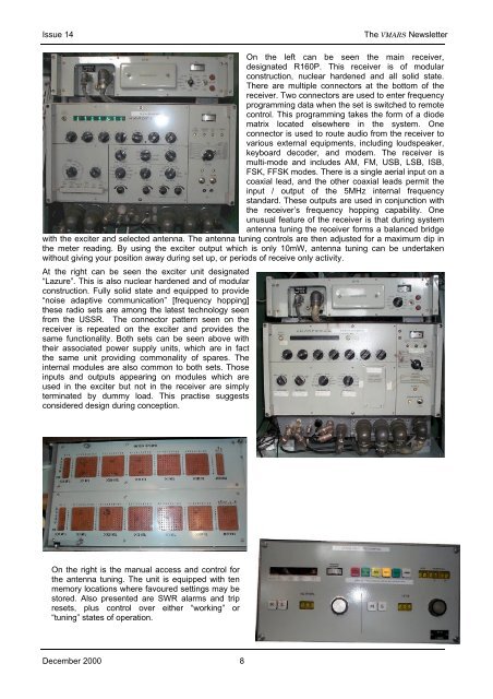
On the left can be seen the main receiver,<br />
designated R160P. This receiver is of modular<br />
construction, nuclear hardened and all solid state.<br />
<strong>The</strong>re are multiple connectors at the bottom of the<br />
receiver. Two connectors are used to enter frequency<br />
programming data when the set is switched to remote<br />
control. This programming takes the form of a diode<br />
matrix located elsewhere in the system. One<br />
connector is used to route audio from the receiver to<br />
various external equipments, including loudspeaker,<br />
keyboard decoder, and modem. <strong>The</strong> receiver is<br />
multi-mode and includes AM, FM, USB, LSB, ISB,<br />
FSK, FFSK modes. <strong>The</strong>re is a single aerial input on a<br />
coaxial lead, and the other coaxial leads permit the<br />
input / output of the 5MHz internal frequency<br />
standard. <strong>The</strong>se outputs are used in conjunction with<br />
the receiver’s frequency hopping capability. One<br />
unusual feature of the receiver is that during system<br />
antenna tuning the receiver forms a balanced bridge<br />
with the exciter and selected antenna. <strong>The</strong> antenna tuning controls are then adjusted for a maximum dip in<br />
the meter reading. By using the exciter output which is only 10mW, antenna tuning can be undertaken<br />
without giving your position away during set up, or periods of receive only activity.<br />
At the right can be seen the exciter unit designated<br />
“Lazure”. This is also nuclear hardened and of modular<br />
construction. Fully solid state and equipped to provide<br />
“noise adaptive communication” [frequency hopping]<br />
these radio sets are among the latest technology seen<br />
from the USSR. <strong>The</strong> connector pattern seen on the<br />
receiver is repeated on the exciter and provides the<br />
same functionality. Both sets can be seen above with<br />
their associated power supply units, which are in fact<br />
the same unit providing commonality of spares. <strong>The</strong><br />
internal modules are also common to both sets. Those<br />
inputs and outputs appearing on modules which are<br />
used in the exciter but not in the receiver are simply<br />
terminated by dummy load. This practise suggests<br />
considered design during conception.<br />
On the left can be seen the peg-board used to<br />
program the ten preset frequencies. This pegboard<br />
is found under the writing surface at the<br />
main console.<br />
On the right is the manual access and control for<br />
the antenna tuning. <strong>The</strong> unit is equipped with ten<br />
memory locations where favoured settings may be<br />
stored. Also presented are SWR alarms and trip<br />
resets, plus control over either “working” or<br />
“tuning” states of operation.<br />
December 2000 8


