USER'S MANUAL - Air Techniques, Inc.
USER'S MANUAL - Air Techniques, Inc.
USER'S MANUAL - Air Techniques, Inc.

You also want an ePaper? Increase the reach of your titles
YUMPU automatically turns print PDFs into web optimized ePapers that Google loves.
INSTALLATION<br />
3. Heat Exhaust Vent Connection. Refer to Figure 9, item (3) and connect the vent hose<br />
(P/N 56057) between the pump heat exchanger and the facility vent line. Secure with two<br />
hose clamps (P/N 89324).<br />
4. Drip Leg Assembly Installation. Using the 2 inch flexible coupling connector (P/N H5159)<br />
supplied, install the Drip Leg Assembly (P/N H5207) to the bottom end of the facility vent line.<br />
Install a length of 1/4 inch OD Urethane Tubing (P/N 51453) between the drip leg and facility<br />
sewer drain. See Figure 10, sheet 2, item (4).<br />
5. Tank Drain to Facility Sewer Connection. Install the last connector adapter (P/N 57253S)<br />
to the tank outlet drain. Connect the last section of 1 ½" ID, clear hose cut for installation to<br />
the adapter. Secure with one 1-9/16"- 2-1/2" diameter hose clamp (P/N 57169). Connect<br />
unconnected hose end to the facility sewer drain as necessary. See Figure 9, item (5).<br />
6. Tank Washout Port to Facility Water Connection. Refer to Figure 9, item (6) and install<br />
a length of 3/8 inch tubing (P/N 19271) between the washout port and the water shutoff valve.<br />
The tubing is provided with Mojave Master Controller Accessory Kit (P/N H5131).<br />
7. Master Controller Assembly Installation. Refer to the installation procedure on the next<br />
page and mount the Master Controller assembly to the equipment room wall.<br />
8. System Electrical Connections. Refer to the Electrical Connections section and connect each<br />
pump and Master Controller to facility power.<br />
Facility Exhaust<br />
Vent Pipe<br />
1/4-inch Vent<br />
Condensation<br />
Drain Port<br />
3<br />
Dual Heat Exhaust<br />
Connection<br />
Details<br />
3/8-inch<br />
Washout Port to<br />
Water Shutoff<br />
Valve Connection<br />
4<br />
Exhaust Vent<br />
Pipe Drip Leg<br />
6<br />
Closed Vented<br />
Drain<br />
5<br />
To Facility<br />
Sewer Drain<br />
Open<br />
Drain<br />
Pipe<br />
MT10 Tank<br />
Tank<br />
Drain<br />
Assembly<br />
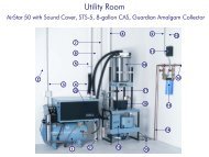
Figure 10. MOJAVE Dual Pump and Tank Connection Diagram, Sheet 2<br />
22