USER'S MANUAL - Air Techniques, Inc.
USER'S MANUAL - Air Techniques, Inc.
USER'S MANUAL - Air Techniques, Inc.

You also want an ePaper? Increase the reach of your titles
YUMPU automatically turns print PDFs into web optimized ePapers that Google loves.
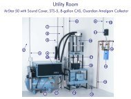
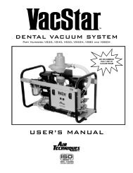
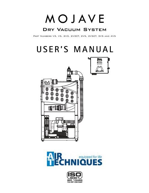
Dry Vacuum System<br />
Part Numbers V3, V5, 2V3, 2V3CT, 2V5, 2V5CT, 3V5 and 4V5<br />
USER’S <strong>MANUAL</strong>
TABLE OF CONTENTS<br />
Description<br />
Congratulations ......................................................4<br />
Safety Summary ......................................................4<br />
Purpose of this Manual. ................................................5<br />
Sizing Guide ........................................................5<br />
Specifications. .......................................................6<br />
Product Description ...................................................7<br />
Installation Information. ............................................... 10<br />
MOJAVE System Configurations ......................................... 14<br />
Installation. ........................................................ 15<br />
V3 and V5 System Installation ......................................... 16<br />
Master Controller Installation .......................................... 19<br />
2V3CT, 2V5CT, 2V3 and 2V5 System Installation ........................... 20<br />
3V5 and 4V5 System Installation ....................................... 23<br />
Electrical Connections ................................................ 26<br />
Operating Information ................................................ 27<br />
Operation ......................................................... 31<br />
Troubleshooting ..................................................... 32<br />
Maintenance ....................................................... 34<br />
Accessories/Options. ................................................. 36<br />
Warranty .......................................................... 37<br />
Page
LIST OF ILLUSTRATIONS<br />
.<br />
.<br />
Figure Description Page<br />
1 Main System Components . . . . . . . . . . . . . . . . . . . . . . . . .8<br />
2 Typical MOJAVE Functional Flow Diagram. . . . . . . . . . . . . . . . . 9<br />
3 MOJAVE System Component Dimensions . . . . . . . . . . . . . . . . . 11<br />
4 V3, 2V3, 2V3CT, V5, 2V5, 2V5CT, 3V5 and 4V5 System Floor Plan . . . . 13<br />
5 MOJAVE System Configuration Layouts . . . . . . . . . . . . . . . . . . 14<br />
6 Stacking the MT10 Tank on Top of a MOJAVE Pump Hardware Detail . . . 15<br />
7 Stacking Two MOJAVE Pumps Hardware Detail . . . . . . . . . . . . . . 15<br />
8 MOJAVE V3/V5 Pump and MT10 Tank Connection Diagram, Sheet 1 . . . 17<br />
8 MOJAVE V3/V5 Pump and MT10 Tank Connection Diagram, Sheet 2 . . . 18<br />
9 MOJAVE Master Controller Assembly and Washout Solenoid Mounting . . 19<br />
10 MOJAVE Dual Pump and Tank Connection Diagram, Sheet 1 . . . . . . . 21<br />
10 MOJAVE Dual Pump and Tank Connection Diagram, Sheet 2 . . . . . . . 22<br />
11 Pump/Tank Connection Manifold Using Accessory Kit . . . . . . . . . . . 25<br />
12 3V5 System Connection Detail Using Accessory Kit . . . . . . . . . . . . 25<br />
13 4V5 System Connection Detail Using Accessory Kit . . . . . . . . . . . . 25<br />
14 MOJAVE Pump Power Connection . . . . . . . . . . . . . . . . . . . . 26<br />
15 Master Controller Wiring Diagram . . . . . . . . . . . . . . . . . . . . 26<br />
16 Master Controller Assembly Controls and Indicators . . . . . . . . . . . . 28<br />
17 Clean Stream Dispenser Cap Adaptor Locations . . . . . . . . . . . . . 36<br />
3
CONGRATULATIONS<br />
Congratulations on the purchase of your new MOJAVE Dry Vacuum System that provides the state<br />
of the art in vacuum technology. This medical grade vacuum system is designed for reliable<br />
operation in the modern dental facility. The system uses a 100% oil-less Vacuum Pump to produce<br />
the high-volume air flow required for multiple simultaneous users while the Separator tank ensures<br />
that no liquids enter the pump.<br />
In addition, MOJAVE incorporates an efficient energy management system. This is accomplished<br />
by adding a Variable Frequency Drive (VFD) to the Vacuum Pump, which is controlled by a Master<br />
Controller. This controller automatically adjusts the frequency of the pump to maintain the required<br />
vacuum level depending on the needs of your dental facility. With this balanced system, each user<br />
always has the flow rate necessary to do the job while conserving electricity and prolonging the life<br />
of your pumps.<br />
SAFETY SUMMARY<br />
Use of MOJAVE not in conformance with the instructions specified in this manual may result in<br />
permanent failure of the unit.<br />
WARNING: To prevent fire or electrical shock, do not expose this appliance<br />
to rain or moisture.<br />
All user serviceable items are described in the maintenance section.<br />
ATTENTION USERS:<br />
Markings. The following terms or symbols are used on the equipment or in this manual to<br />
denote information of special importance:<br />
Alerts users to important Operating<br />
and Maintenance instructions. Read<br />
carefully to avoid any problems.<br />
Warns users of hot surfaces. There is a danger<br />
of burns. Work near these surfaces only after<br />
they have cooled down.<br />
Warns users that uninsulated voltage<br />
within the unit may be of sufficient<br />
magnitude to cause electric shock.<br />
Identifies the name of the<br />
manufacturer.<br />
Indicates date of manufacture<br />
I ON<br />
O OFF<br />
Indicates the ON and OFF position for<br />
the Equipment power switch.<br />
Indicates protective Earth Ground for the<br />
Equipment power switch.<br />
CLASSIFIED<br />
MEDICAL ELECTRICAL EQUIPMENT<br />
WITH RESPECT TO ELECTRICAL SHOCK, FIRE, MECHANICAL<br />
AND OTHER SPECIFIED HAZARDS ONLY<br />
IN ACCORDANCE WITH UL-60601-1, CAN/CSA C22.2 NO.601.1<br />
66CA<br />
4
PURPOSE OF THIS <strong>MANUAL</strong><br />
This manual provides installation, operation and maintenance instructions for the support of the six<br />
available MOJAVE Dry Vacuum System configurations listed below. Although not listed, each system<br />
also includes a Master Controller. Review and follow the guidelines included in this User Manual to<br />
ensure that the system provides the highest level of service.<br />
System<br />
Description<br />
Maximum<br />
Users<br />
V3 One V3 Dry Vacuum Pump and an MT10 Tank 3<br />
V5 One V5 Dry Vacuum Pump and an MT10 Tank 5<br />
2V3 Two V3 Dry Vacuum Pumps and an MT10 Tank 6<br />
2V3CT Two V3 Dry Vacuum Pumps and a CT20 Tank 6<br />
2V5 Two V5 Dry Vacuum Pumps and an MT10 Tank 10<br />
2V5CT Two V5 Dry Vacuum Pumps and a CT20 Tank 10<br />
3V5 Three V5 Dry Vacuum Pumps and a CT20 Tank 15<br />
4V5 Four V5 Dry Vacuum Pumps and a CT20 Tank 20<br />
SIZING GUIDE<br />
Choosing the right configuration of Mojave for your practice depends on the number of air users<br />
and the anticipated air demand. To ensure optimum operation, the demands should not exceed the<br />
number of air handpiece users shown below. The chart lists the number of simultaneous High Volume<br />
Evacuators (HVEs) and Saliva Ejectors (SEs) that can be used in specific MOJAVE system configurations.<br />
V3 System<br />
Recommended Number of Simultaneous HVE/SE Users<br />
V5 System<br />
2V3 or 2V3CT<br />
System<br />
2V5 or 2V5CT<br />
System<br />
3V5 System<br />
4V5 System<br />
HVE SE HVE SE HVE SE HVE SE HVE SE HVE SE<br />
3 + 0 5 + 0 6 + 0 10 + 0 15 + 0 20 + 0<br />
2 + 2 4 + 2 5 + 2 9 + 2 14 + 2 18 + 4<br />
0 + 6 2 + 6 3 + 6 7 + 6 12 + 6 13 + 14<br />
0 + 10 1 + 10 5 + 10 9 + 12 10 + 20<br />
0 + 12 3 + 14 6 + 18 8 + 24<br />
1 + 18 2 + 26 5 + 30<br />
0 + 20 0 + 30 0 + 40<br />
Note: 1 HVE = 2 SE’s / 1 HVE = 2 Nitrous Scavengers<br />
5
SPECIFICATIONS<br />
Master Controller Electrical Specifications<br />
Voltage (Volts AC) 120 (± 10%)<br />
Full Load Current (Amps AC) 5<br />
Input Frequency (Hz) 60<br />
Pump Electrical Specifications V3 V5<br />
2V3 &<br />
2V3CT<br />
2V5 &<br />
2V5CT<br />
3V5<br />
4V5<br />
Voltage (Volts AC) 205 - 240 205 - 240 205 - 240 205 - 240 205 - 240 205 - 240<br />
Full Load Current (Amps AC) 12 15 24 30 45 60<br />
Input Frequency (Hz) 60 60 60 60 60 60<br />
Preset Vacuum Level (InHg) 8 8 8 8 8 8<br />
Horsepower (each V3 or V5 pump )<br />
1.1 kW or 1.5 HP<br />
Tank Specifications V3, V5, 2V3 & 2V5 2V3CT, 2V5CT, 3V5 & 4V5<br />
Working Liquid Capacity<br />
MT10 Tank<br />
10 gallon maximum capacity<br />
CT20 Continuum Tank<br />
infinite volume capacity<br />
Tank Material (All systems) Rotomolded Plastic Rotomolded Plastic<br />
System Environmental Conditions (All Systems)<br />
Operating Temperature 40 to 104°F or 10 to 40°C<br />
Storage Temperature 0 to 150°F or -18 to 66°C<br />
Relative Humidity<br />
90%, no condensation<br />
UL60601-1 CLASSIFICATION<br />
Protection against electrical shock (5.1, 5.2) Class I, Transportable, Continuous Operation. No applied parts.<br />
Protection against ingress of liquids-Ordinary Equipment not suitable for use in the presence of flammable anaesthetic<br />
mixture with air or with oxygen or nitrous oxide.<br />
All MOJAVE vacuum pumps comply with NFPA 99C level 3 requirements.<br />
6
As shown by Figure 1, the MOJAVE Dry Vacuum System consists of the major components listed below.<br />
Vacuum Pump Assemblies V3 or V5.<br />
PRODUCT DESCRIPTION<br />
A single-stage pump, where all of the wetted metal parts are nickel plated or stainless steel.<br />
A metal electrical enclosure that houses a VFD (Variable Frequency Drive), circuit breaker, and<br />
an interface PCB.<br />
An aluminum heat exchanger to cool the exhaust air from the pump before it travels through<br />
the exhaust vent.<br />
A metal chassis for mounting components.<br />
10 Gallon Separation Tank Assembly MT10.<br />
A molded plastic tank that is capable of holding 10 gallons of liquid.<br />
An internal float switch that signals the Master Controller to turn the vacuum pump OFF if<br />
the liquid level exceeds the preset level.<br />
A washout port with internal nozzle that is used to rinse the interior of the tank during the<br />
automatic Washout Cycle.<br />
A metal chassis for mounting components.<br />
Continuum Separation Tank Assembly CT20.<br />
The continuum tank combines two molded plastic tanks connected via a check valve and<br />
two solenoid valves. This tank is capable of handling an infinite volume of liquid because<br />
one tank section drains as the other tank section fills, while maintaining a preset vacuum<br />
level.<br />
Each tank has an internal float switch that signals the Master Controller to toggle the state<br />
of each tank solenoid.<br />
Solenoids keep the liquid moving through the tanks by controlling the venting and pressurization<br />
of each tank.<br />
Each tank has a washout port with internal nozzle that is used to rinse the interior of the tank<br />
during the automatic Washout Cycle.<br />
A metal chassis for mounting components.<br />
Master Controller. A Main PCB, Front Panel PCB and an LCD Display PCB mounted in a metal<br />
Enclosure that:<br />
Provides the operational user interface for the MOJAVE system.<br />
Monitors and displays the frequency, vacuum level and temperature.<br />
Records the run time, in hours, of up to 4 connected pumps.<br />
Balances the vacuum load equally across all running pumps.<br />
Displays any error/fault codes.<br />
Controls the Washout function.<br />
7
PRODUCT DESCRIPTION<br />
Heat<br />
Exchanger<br />
Exhaust Vent<br />
Connection<br />
<strong>Air</strong> Inlet Port<br />
with Filter<br />
Motor Wire<br />
Harness<br />
Serial<br />
Plate<br />
Vacuum<br />
Pump<br />
Heat<br />
Exchanger<br />
Electrical<br />
Box<br />
Electrical<br />
Box<br />
Detail<br />
Power Switch with<br />
Circuit Breaker<br />
V3 and V5 Vacuum Pumps<br />
<strong>Air</strong> Inlet Port<br />
with Filter<br />
Leveling<br />
Feet<br />
Tank Outlet<br />
to Pump<br />
Tank Outlet to Pump<br />
Tank & <strong>Air</strong><br />
Solenoids<br />
Washout Port<br />
Tank Inlet<br />
from<br />
Operatory<br />
Tank Inlet from Operatory<br />
Washout Port<br />
Float<br />
Switch<br />
Check<br />
Valve<br />
Check Gate Tank Drain<br />
Valve Valve<br />
MT10 Tank Front View<br />
Leveling Feet<br />
CT20 Tank Rear View<br />
Check Gate<br />
Tank Drain<br />
Valve Valve<br />
CT20 Tank Front View<br />
Leveling<br />
Feet<br />
Vacuum Inlet<br />
Port<br />
Panel Knockouts<br />
for CAT 5 Cable<br />
(10-feet) to Pumps<br />
Front Panel Controls<br />
and Indicators<br />
Low Voltage Control<br />
Panel Switch and<br />
Float Switches<br />
Door Retainer 1/4<br />
Turn Screws<br />
Master Controller<br />
24 VAC Output<br />
Panel Knockouts for<br />
Solenoid Outputs<br />
120 VAC Output<br />
Circuit Breakers<br />
AC Power IEC Receptacle<br />
(Note: The 10-foot Line Cord is the<br />
Mains disconnect device for<br />
the Master Controller.)<br />
Figure 1. Main System Components<br />
8
PRODUCT DESCRIPTION<br />
Any time the power to the MOJAVE is turned<br />
OFF the tanks will automatically drain.<br />
Vacuum System Operation.<br />
<strong>Air</strong>, water, and solids from the operatory are pulled into the separator tank. <strong>Air</strong> is expelled out through<br />
the pump exhaust while liquids and solids fall to the bottom of the tank. The vacuum in the tank keeps<br />
the check valve to the drain closed and the tank gradually fills.<br />
In single tank (MT10) configurations, if the rising fluid level actuates the float switch, the Master Controller<br />
stops the operation of all connected pumps and an optional drain pump (sold separately) is turned on for<br />
one minute. With pump operation idle, the vacuum is no longer being maintained and the check valve<br />
of the tank drain opens allowing liquids and solids to drain from the separator tank. Once the tank<br />
drains, the Master Controller automatically restarts the primary pump.<br />
Systems using the continuum tank (CT20), which is capable of handling infinite liquid volume capacities,<br />
operate differently. Each tank has an internal float switch. The tanks also use two 2-way solenoids.<br />
The float switches control the state of the two solenoids to allow the filling and draining of each<br />
tank, keeping the liquid moving through the tanks. When the top tank is filling, the bottom tank<br />
is draining and when a bottom tank is filling, the top tank is draining. The preset vacuum level is<br />
maintained in either state. If the top float switch is active, the Master Controller stops the operation of all<br />
connected pumps. Additionally, whenever the bottom tank float switch is activated, an optional drain pump<br />
(sold separately) is turned on for one minute. Once the tank drains, the Master Controller automatically<br />
restarts the primary pump.<br />
When an instrument (suction tip) has been opened, the Master Controller senses an increase in vacuum<br />
demand and will instruct the VFD to speed up the motor.<br />
Conversely, when an instrument (suction tip) has been closed, the Master Controller will instruct the VFD<br />
to slow motor operation down due to decrease vacuum demand. The Master Controller can also turn<br />
on and off up to 4 connected pumps to regulate the vacuum level.<br />
Additionally, the Master Controller initiates a 2-minute tank washout cycle when the system has been in<br />
Standby for 5 minutes.<br />
From<br />
Treatment<br />
Room<br />
Gas/Liquids/<br />
Solids<br />
Gas<br />
Exhaust to<br />
Outside Vent<br />
MT10<br />
or CT20<br />
Separator<br />
Tank<br />
Liquids/Solids<br />
Heat<br />
Exchanger<br />
Sewer<br />
Drain<br />
Check<br />
Valve<br />
Gate<br />
Valve<br />
V3 or V5<br />
Vacuum<br />
Pump<br />
<strong>Air</strong> Inlet Port<br />
Filter<br />
Figure 2. Typical MOJAVE Functional Flow Diagram<br />
9
INSTALLATION INFORMATION<br />
Grounding reliability can only be achieved when<br />
the Master Controller is connected to a HOSPITAL<br />
GRADE receptacle.<br />
General. For new installations it is recommended to follow the following guidelines:<br />
Make sure to install the system in accordance with all local electrical and plumbing codes.<br />
Sizes of each suction line from the operatories differ between MOJAVE systems. See Site<br />
Requirements provided on page 12.<br />
The suction line should not have any sharp right angle bends and must be sloped a minimum<br />
of ¼ inch for every 10 feet toward the separation tank.<br />
The drain on the base of the separation tank must be connected to a vented or an open floor<br />
drain capable of handling 10 gallons in 30 seconds. Drain pipe size 1 ½ inch schedule 40.<br />
The drain line should be a short run with a minimum slope of ¼ inch for every 10 feet toward<br />
the drain (avoid any sharp right angle bends).<br />
Vent line requirements differ among MOJAVE systems. See Site Requirements.<br />
Make sure to install the supplied drip leg assembly to the bottom end of the facility vent line.<br />
The vent should be sloped ¼ inch per 10 feet towards the pump. Vent lines must be capable<br />
of handling vapors and liquids.<br />
The outside vent must be protected from rain and animals.<br />
A flexible air exhaust hose is provided to connect to the 2 inch diameter vent pipe and heat<br />
exchanger. Hose clamps are provided to secure hose to heat exchanger and pipe.<br />
Wash-out water supplied via ½ inch copper tubing terminated with a ½ inch FNPT shut-off<br />
valve providing water pressure between 20 and 100 psi.<br />
Wash-out port on the tank top is a 3 ∕8 inch push to connect elbow that connects to the water supply<br />
via supplied 10 foot 3 ∕8 inch Poly tubing and ½ MNPT x 3 ∕8 inch push to connect adapter.<br />
As shown by Figure 4, the Master Controller is secured to the wall between the facility water<br />
supply and the tank using two 10-32 wall anchors. In addition to the water connection at the<br />
washout solenoid, electrical and vacuum connections must also be made.<br />
Accessory packs and system installation kits shipped with associated MOJAVE systems are<br />
listed below. Refer to the Installation Section for a listing of components supplied with each<br />
kit and the instructions necessary to install specific MOJAVE systems.<br />
MOJAVE Accessory Packs and System Installation Kits<br />
Part No. Description <strong>Inc</strong>luded With<br />
H5131 Master Controller Accessory Pack Ships with every Master Controller<br />
H5210 MT10 Tank Accessory Pack Ships with every MT10 tank<br />
H5170 MOJAVE V3 and V5 Pump Accessory Pack Ships with every V3 Pump and V5 Pump<br />
MIK2 MOJAVE Dual System Installation Kit<br />
Ships with every 2V3 ,2V5, 2V3CT and<br />
2V5CT System<br />
MIK4 MOJAVE Triple and Quad System Installation Kit Ships with every 3V5 and 4V5 System<br />
10
INSTALLATION INFORMATION<br />
Physical Characteristics<br />
Master<br />
Controller<br />
MT10<br />
10 Gallon<br />
Tank<br />
CT20<br />
Continuum<br />
One<br />
V3 or V5<br />
Pump<br />
Two<br />
V3 or V5 Pumps<br />
Stacked<br />
Three<br />
V5 Pumps<br />
Stacked<br />
Width 11 in. (28 cm) 25 in. (64 cm) 25 in. (64 cm) 25 in. (64 cm) 25 in. (64 cm) 25 in. (64 cm)<br />
Depth 3 in. (8 cm) 17 in. (43 cm) 20 in. (51 cm) 19 in. (48 cm) 19 in. (48 cm) 19 in. (48 cm)<br />
Height 10 in. (24 cm) 23 in. (58 cm) 42 in. (107 cm) 17 in. (43 cm) 34 in. (86 cm) 51 in. (130 cm)<br />
Weight 13 Lbs. (6 kg) 75 Lbs. (34 kg) 150 Lbs. (68 kg) 145 Lbs (66 kg) 290 Lbs (132 kg) 435 Lbs (197 kg)<br />
13.5 in. (34 cm)<br />
11 in. (28 cm)<br />
3 in.<br />
(8 cm)<br />
19 in. (48 cm)<br />
11 in.<br />
(28 cm)<br />
10 in.<br />
(24 cm)<br />
15.5 in.<br />
(39 cm)<br />
25 in. (64 cm)<br />
17 in.<br />
(43 cm)<br />
Master Controller Dimensions<br />
V3 and V5 Vacuum Pump Dimensions<br />
20 in.<br />
(51 cm)<br />
28.5 in.<br />
(72 cm)<br />
17 in.<br />
(43 cm)<br />
20 in.<br />
(51 cm) 25 in. (64 cm)<br />
42 in.<br />
(107 cm)<br />
33 in.<br />
(84 cm)<br />
MT10 10 Gallon Tank Dimensions<br />
CT20 Continuum Tank Dimensions<br />
Figure 3. Mojave System Component Dimensions<br />
11
INSTALLATION INFORMATION<br />
Site Requirements<br />
Electrical V3 V5<br />
2V3 &<br />
2V3CT<br />
2V5 &<br />
2V5CT<br />
3V5<br />
4V5<br />
Master<br />
Controller<br />
Voltage Rating Volts AC 220 220 220 220 220 220 120<br />
Voltage Minimum/<br />
Maximum<br />
Wire Size AWG Minimum<br />
Gauge<br />
Minimum Circuit Breaker<br />
Rating<br />
205/240 205/240 205/240 205/240 205/240 205/240 108/132 Volts AC<br />
#12 AWG<br />
(Qty 1)<br />
#12 AWG<br />
(Qty 1)<br />
#12 AWG<br />
(Qty 2)<br />
#12 AWG<br />
(Qty 2)<br />
#12 AWG<br />
(Qty 3)<br />
#12 AWG<br />
(Qty 4)<br />
#14 AWG<br />
20A 20A 20A (Qty 2) 20A (Qty 2) 20A (Qty 3) 20A (Qty 4) 15A<br />
<strong>Inc</strong>oming Power<br />
Hard wire Connection<br />
(Each pump is supplied with a 4 x 4 handy box and a 4 foot whip)<br />
NEMA 5-15R<br />
(Supplied 10-ft. line cord)<br />
Plumbing V3 V5<br />
2V3 &<br />
2V3CT<br />
2V5 &<br />
2V5CT<br />
3V5<br />
4V5<br />
Exhaust Vent Pipe Using<br />
Heat Exchanger<br />
2” PVC<br />
Sch. 40<br />
2” PVC<br />
Sch. 40<br />
One 3” or two<br />
2” PVC Sch. 40<br />
One 3” or two<br />
2” PVC Sch. 40<br />
One 4” or three<br />
2” PVC Sch. 40<br />
Two 3” or four<br />
2” PVC Sch. 40<br />
Exhaust Vent Pipe Not<br />
Using Heat Exchanger<br />
(See note 1)<br />
2” Metal<br />
Pipe<br />
2” Metal<br />
Pipe<br />
One 3” or two 2”<br />
Metal Pipe<br />
One 3” or two<br />
2” Metal Pipe<br />
One 4” or three<br />
2” Metal Pipe<br />
Two 3” or four<br />
2” Metal Pipe<br />
Minimum Suction Line Pipe<br />
1” PVC<br />
Sch. 40<br />
1 ½” PVC<br />
Sch. 40<br />
1 ½” PVC<br />
Sch. 40<br />
2” PVC<br />
Sch. 40<br />
3” PVC<br />
Sch. 40<br />
3” PVC<br />
Sch. 40<br />
Maximum Suction Line Pipe<br />
(See note 2)<br />
1 ½” PVC<br />
Sch. 40<br />
2” PVC<br />
Sch. 40<br />
2” PVC<br />
Sch. 40<br />
2 ½” PVC<br />
Sch. 40<br />
4” PVC<br />
Sch. 40<br />
4” PVC<br />
Sch. 40<br />
Riser Pipe<br />
½” PVC<br />
Sch. 40<br />
½” PVC<br />
Sch. 40<br />
½” PVC<br />
Sch. 40<br />
½” PVC<br />
Sch. 40<br />
½” PVC<br />
Sch. 40<br />
½” PVC<br />
Sch. 40<br />
Vacuum Line Termination 1 ½” FNPT 2” FNPT 2” FNPT 2” FNPT 2” FNPT 2” FNPT<br />
Branch Line Pipe<br />
Size requirement of Branch piping differs by the number of operatories being serviced.<br />
Up to two operatories use 1" PVC Schedule 40.<br />
Three to six operatories use 1 ½” PVC Schedule 40.<br />
More that six operatories use 2" PVC Schedule 40<br />
Drain Line Pipe 1 ½” PVC Schedule 40<br />
Wash-Out Water Line<br />
½” FNPT Shut-off Valve<br />
NOTES<br />
1. Recommended for all new installations.<br />
2. Use maximum internal diameter for the main line when preparing any new installation.<br />
12
INSTALLATION INFORMATION<br />
Installation Layout Space. Figure 4 shows the requirements for the installation of the various<br />
MOJAVE model configurations. Please note that all units are shipped with leveling feet set to lowest<br />
position. Heights can be increased by 1 inch by adjusting the leveling feet. Refer to Figure 5 for the<br />
recommended configuration arrangements.<br />
48"<br />
D<br />
4"<br />
12"<br />
E<br />
4"<br />
F<br />
C<br />
24"<br />
G<br />
62"<br />
4"<br />
H<br />
12"<br />
J<br />
1"<br />
4"<br />
24"<br />
K<br />
Pump/Tank<br />
Connection Manifold<br />
4"<br />
80"<br />
L<br />
20"<br />
Sewer Drain<br />
MT10 or CT20<br />
Tank<br />
B<br />
76"<br />
A<br />
Single or<br />
Stacked Pumps<br />
(V3 or V5)<br />
Single or<br />
Stacked Pumps<br />
(V3 or V5)<br />
A<br />
23"<br />
107"<br />
Installation Notes.<br />
A. PUMP INSTALLATION SPACE - Area for stacked V3 or V5 pumps in typical side by side installations. Only<br />
stack up to 2 pumps in one area.<br />
B. TANK INSTALLATION SPACE - Area for MT10 or CT20 tank in typical side by side installations. Never install<br />
the CT20 tank on top of a pump.<br />
C. SEWER DRAIN - Provide a drain for the removal of waste liquids from the MOJAVE tank. Use an open drain<br />
pipe (1 ½” inch P-Trap with 1 inch air gap or floor sink) or a closed vented drain. See detail 1.<br />
D. TANK WASHOUT - Provide a water source terminated with a ½ inch FNPT shut-off valve providing water<br />
pressure between 20 and 100 psi for daily tank washout. Valve location must be no more than 10 feet from<br />
the tank installation to allow connection of supplied 10-foot 3/8-inch Poly tubing to the tank washout port.<br />
Provisions for backflow prevention may be required. Check local code requirements.<br />
E. MASTER CONTROLLER UNIT - Locate near pump and also allow a space around the Master Controller of at<br />
least 4 inches for the connection of wiring and the line cord during installation and servicing.<br />
F. MASTER CONTROLLER ELECTRIC OUTLET - Master Controller requires a dedicated standalone 120V, hospital<br />
grade grounded receptacle. The supplied 10-foot line cord is the Mains disconnect device for the unit.<br />
G. PUMP ELECTRIC SERVICE - Each Mojave pump is wired directly with a dedicated 220V, 20 AMP, single phase<br />
60 Hz circuit. If Main Circuit panel is not located in equipment room, a disconnect box with approved ground<br />
is needed for each pump. Disconnect boxes should be mounted no more than 3 feet of each other and 3 feet<br />
of installation center line.<br />
H. Sub FLOOR INSTALLATION VACUUM LINE - See Plumbing Requirements for connection to tank inlet via supplied<br />
hose.<br />
J. Overhead INSTALLATION VACUUM LINE - See Plumbing Requirements for connection to tank inlet via supplied<br />
hose.<br />
K. HEAT EXHAUST - See Plumbing Requirements for the exhaust vent line required for specific Mojave configurations.<br />
Use metal pipe on systems whenever the Heat Exchanger is removed. Schedule 40 pipe can normally be used on<br />
typical Mojave configuration installations with a Heat Exchanger. When installing two pumps, a reducing Y adapter<br />
(shown by detail 2 above) is needed to connect both vent tubes to a common 3-inch exhaust vent line.<br />
L. PUMP/TANK MANIFOLD - User fabricated to connect 3 or 4 pumps to a tank. Used with 3V5 and 4V5 systems.<br />
See Pump/Tank Connection Manifold.<br />
Figure 4. V3, 2V3, 2V3CT, V5, 2V5, 2V5CT, 3V5 and 4V5 System Floor Plan<br />
13
MOJAVE SYSTEM CONFIGURATIONS<br />
Important:<br />
Side by side installation of pump and tank is preferred.<br />
Stack a MT10 tank on top of one V3 or V5 pump only if space is a problem.<br />
V3 or V5 pumps should only be stacked two high in all other system configurations as shown.<br />
All units are shipped with leveling feet set to lowest position.<br />
V3 or V5 System Side by Side Installation<br />
V3 or V5 System<br />
Stacked<br />
2V3 or 2V5 System Installation<br />
Recommended Stacked Pumps with Tank on Side<br />
Recommended One Pump, a Stack of two Pumps & a CT20 Tank<br />
Alternate Stack Three Pumps & a CT20 Tank<br />
(Use only to meet space requirements.)<br />
3V5 System Installation<br />
4V5 System Installation<br />
Recommended Two Side by Side Stacks of Two Pumps and a CT20 Tank<br />
Figure 5. MOJAVE System Configuration Layouts<br />
14
INSTALLATION<br />
MT10<br />
TANK<br />
1/4-20 X 1/2" HEX<br />
Bolt (Quantity 4)<br />
1/4" Lock Washer<br />
(Quantity 4)<br />
MOJAVE<br />
PUMP<br />
(V3 or V5)<br />
Note: See MOJAVE V3 and V5 Pump Accessory Pack, P/N H5170,<br />
for required fastener hardware.<br />
Remove leveling feet from pump or tank to be stacked.<br />
Figure 6. Stacking the MT10 Tank on Top of a MOJAVE Pump Hardware Detail<br />
1/4-20 X 1/2" HEX<br />
Bolt (Quantity 4)<br />
1/4" Lock Washer<br />
(Quantity 4)<br />
TWO<br />
V3 or V5<br />
MOJAVE<br />
PUMPS<br />
Note: See MOJAVE V3 and V5 Pump Accessory Pack, P/N H5170,<br />
for required fastener hardware.<br />
Remove leveling feet from pump or tank to be stacked.<br />
Figure 7. Stacking Two MOJAVE Pumps Hardware Detail<br />
15
INSTALLATION<br />
V3 and V5 System Installation.<br />
Note: Each kit provides the required hoses, clamps and adapters.<br />
No schedule 40 PVC pipe is included.<br />
Installation Accessory Packs. Figure 8, sheet 1 and 2 show the hose connections required for all V3<br />
and V5 MOJAVE System configuration installations using accessory packs that provide the required<br />
hoses, clamps and adapters as follows:<br />
MOJAVE V3 and V5 Pump Accessory Pack, P/N H5170 - supplied with each pump and<br />
is used as follows.<br />
Secure the MT10 Tank on top of the associated MOJAVE pump as shown by Figure 6.<br />
Connect the pump to the facility vent line, connection item (3) on Figure 8, sheet 2.<br />
MT10 Tank Accessory Pack, P/N H5210 - used to make the following connections:<br />
Between the suction line and tank inlet. Item (1) on Figure 8, sheet 1.<br />
Between the tank air outlet and pump inlet. Item (2) on Figure 8, sheet 1.<br />
Install a drip leg to the facility vent line, connection item (4) on Figure 8, sheet 2.<br />
The tank outlet drain to the facility sewer drain. Item (5) on Figure 8, sheet 2.<br />
The washout port to the water shutoff valve. Item (6) on Figure 8, sheet 2.<br />
Accessory Pack Supplied Components. The supplied components of accessory packs (P/Ns H5170<br />
& H5210) are listed below. Verify that all listed items were received. If any item is missing, notify your<br />
dealer.<br />
V3 and V5 Pump Accessory Pack, P/N H5170<br />
Part No. Description Qty<br />
56057 Vent Hose, 2-1/4" ID X 17" Long 1" W Cuff 1<br />
89324 Hose Clamp 1-9/16"- 2-1/2" Maximum 2<br />
57169 Hose Clamp 1.31 - 2.25 Diameter 2<br />
419342 10 Foot CAT5e Network Cable 1<br />
30914 Bolt 1/4-20 X 1/2, HEX Head,18-8 4<br />
30958 1/4" Flat Washer 4<br />
30920 1/4" Split Lock Washer 4<br />
MT10 Tank Accessory Pack, P/N H5210<br />
Part No. Description Qty<br />
54521 1 ½" ID, Clear Hose with Blue Helix 10 FT 1<br />
57253S Connector Adapter, 1 ½" MNPT X 1 ½" Barb 3<br />
57169 Hose Clamp 1.31 - 2.25 Diameter 3<br />
H5206 Tank Outlet Assembly; Single Pump 1<br />
51453 Urethane Tubing, 1/4 OD 15 FT 1<br />
54434 Connector Adapter, 1 ½" SPG X 1 ½" FNPT 1<br />
H5207 Drip Leg Assembly 1<br />
H5159 2” Flexible Coupling Connector 1<br />
Installation Setup. Installation of a V3 and V5 MOJAVE System configuration consists of placing<br />
the equipment in the proper installation space and making connections between a MT10 tank and<br />
a V3 or V5 pump.<br />
1. Refer to Figures 4 and 5 and determine the installation footprint dimensions and connection<br />
requirements. Place the tank and pump in position as shown by Figure 4.<br />
2. If installing side-by-side configuration, proceed to step 4. If stacking, perform step 3.<br />
3. When stacking the MT10 tank on top of a pump, refer to Figure 6 and secure the tank<br />
to pump using hardware supplied by the Pump Accessory Pack, P/N H5170. When<br />
stacking any MOJAVE system component, make sure to secure installation with the wall<br />
mount bracket kit available from your dealer.<br />
Note: If more than 10 feet of the 1 ½" ID, Clear Hose hose is needed,<br />
order P/N 54521 (order by the foot)<br />
4. Measure and record distance between each connection point. Cut the supplied hose to<br />
the length required for each connection.<br />
16
INSTALLATION<br />
V3 and V5 Connection Procedure. Using industry standard techniques, make the connections<br />
between the tank and pump with supplied components of accessory packs (P/Ns H5170 & H5210).<br />
Refer to Figure 8, sheets 1 and 2 for the connection diagram and perform the following procedure.<br />
1. Suction Line to Tank Inlet Connection. Refer to Figure 8, item (1) .<br />
a. Install one connector adapter (P/N 57253S) to the pipe from the operatory.<br />
b. Install the connector adapter (P/N 54434) into the flexible coupling connector on the tank.<br />
Screw the barb side of the adapter (P/N 57253S) into the FNPT side.<br />
c. Install the 1½" ID, clear hose (P/N 54521) cut for installation between the operatory suction<br />
line and tank inlet and secure with two hose clamps (P/N 57169).<br />
Note: If more than 15 feet of the 1/4 inch OD Urethane Tubing is needed,<br />
order P/N 51453 for additional 15 foot lengths.<br />
2. Tank <strong>Air</strong> Outlet to Pump Inlet Connection. Refer to Figure 8, item (2) .<br />
a. Install the Single Pump Tank Outlet Assembly (P/N H5206) onto the tank outlet port<br />
and secure with the two hose clamps. The outlet assembly is provided with MT10 Tank<br />
Accessory Pack (P/N H5210).<br />
b. Connect 1 ½" ID, clear hose (P/N 54521) cut for installation between the barb connectors<br />
of the Single Pump Tank Outlet Assembly and pump air inlet filter. Secure with two hose<br />
lamps (P/N 57169).<br />
c. Install a length of 1/4 inch OD Urethane Tubing (P/N 51453) between the vacuum sample<br />
port and the vacuum inlet port of the Master Controller. See Figure 8, item (2a.)<br />
Single Pump<br />
Tank Outlet<br />
Assembly<br />
Detail<br />
2a<br />
1/4-inch Vacuum<br />
Sample Port to<br />
Master Controller<br />
1<br />
Facility Piping from<br />
Operatory<br />
V3 or V5<br />
Pump<br />
Tank <strong>Air</strong> Outlet<br />
to Pump Inlet<br />
Connection<br />
2<br />
Tank Inlet<br />
Detail<br />
MT10 Tank<br />
Tank Inlet<br />
Flexible Coupling<br />
Connector<br />
Pump Inlet<br />
Connection Detail<br />
Important: Make sure to efficiently use space by making connections<br />
as short and direct as possible to meet<br />
your particular site requirements.<br />
Make sure that all hose connections are straight<br />
and secure without any sharp bends or kinks.<br />
Since the vacuum hose is rigid, make sure not to<br />
stress connections especially at the pump inlet.<br />
Figure 8. MOJAVE V3/V5 Pump and MT10 Tank Connection Diagram, Sheet 1<br />
17
INSTALLATION<br />
3. Heat Exhaust Vent Connection. Refer to Figure 8, item (3) and connect the vent hose<br />
(P/N 56057) between the pump heat exchanger and the facility vent line. Secure with two<br />
hose clamps (P/N 89324).<br />
4. Drip Leg Assembly Installation. Using the 2 inch flexible coupling connector (P/N H5159)<br />
supplied, install the Drip Leg Assembly (P/N H5207) to the bottom end of the facility vent line.<br />
Install a length of 1/4 inch OD Urethane Tubing (P/N 51453) between the drip leg and facility<br />
sewer drain. See Figure 8, item (4).<br />
5. Tank Drain to Facility Sewer Connection. Install the last connector adapter (P/N 57253S)<br />
to the tank outlet drain. Connect the last section of 1 ½" ID, clear hose cut for installation to<br />
the adapter. Secure with one 1-9/16"- 2-1/2" diameter hose clamp (P/N 57169). Connect<br />
unconnected hose end to the facility sewer drain as necessary. See Figure 8, item (5).<br />
6. Tank Washout Port to Facility Water Connection. Refer to Figure 8, item (6) and install<br />
a length of 3/8 inch tubing (P/N 19271) between the washout port and the water shutoff valve.<br />
The tubing is provided with Mojave Master Controller Accessory Kit (P/N H5131).<br />
7. Master Controller Installation. Refer to the installation procedure on the next page and<br />
mount the Master Controller to the equipment room wall.<br />
8. System Electrical Connections. Refer to the Electrical Connections section and connect the<br />
pump and Master Controller to facility power.<br />
Facility Exhaust<br />
Vent Pipe<br />
3<br />
Heat Exhaust<br />
Connection Detail<br />
1/4-inch Vent<br />
Condensation<br />
Drain Port<br />
4<br />
Exhaust Vent<br />
Pipe Drip Leg<br />
3/8-inch<br />
Washout Port to<br />
Water Shutoff<br />
Valve Connection<br />
6<br />
Closed Vented<br />
Drain<br />
5<br />
To Facility<br />
Sewer Drain<br />
Open<br />
Drain<br />
Pipe<br />
MT10 Tank<br />
Tank<br />
Drain<br />
Assembly<br />
Figure 8. MOJAVE V3/V5 Pump and MT10 Tank Connection Diagram, Sheet 2<br />
18
INSTALLATION<br />
Master Controller Installation. The Master Controller is mounted on the equipment room wall<br />
between the facility water supply and the associated tank (MT10 or CT20). The water connection at<br />
the washout solenoid, electrical and vacuum connections must also be made at the unit. Review the<br />
important considerations listed below and install the Master Controller:<br />
1. Locate the Master Controller near the pump and allow a space around the Master Controller of<br />
at least 4 inches for the connection of wiring and the line cord during installation and servicing.<br />
2. To avoid electrical shorting from dripping water, always make sure to install the Master Controller<br />
above the facility water supply line.<br />
3. The pump is turned ON from either the Primary Pump Local ON/OFF Switch located on the<br />
Master Controller or from a remote location with the optional Remote Control Panel Switch.<br />
4. Use standard industry guidelines for working with electrical circuits, plumbing and on electronic<br />
equipment as necessary.<br />
5. Make sure to efficiently use space by making connections as short and direct as possible to meet<br />
your particular site requirements.<br />
6. Each CAT 5 Cable used to connect the Master Controller and associated Pump is 10 feet long.<br />
Accessory Pack Supplied Components. The supplied components of accessory pack (P/N H5131)<br />
is listed below. Verify that all listed items were received. If any item is missing, notify your dealer.<br />
Mojave Master Controller Accessory Kit, P/N H5131<br />
Part No. Description Qty<br />
77243 Line Cord 10 FT, 18 GA., IEC X North America, Hospital Grade 1<br />
H5130 Tank Washout Solenoid Assembly; 1/2" NPT, 115VAC 1<br />
19271 Poly Tubing, 3/8" OD 10 FT 1<br />
30936 Plastic Screw Anchor, #10-12 X 1" , RAWL#7579 4<br />
30295 #10 X 3/4, Type A, Plated Slot Pan Head Screw 4<br />
30711 10-24 X 1/2, T- Form, Plated HEX Wash Head Screw 2<br />
56194 Connector Adapter,1/2 MNPT X 3/8 PUSH: SMC# KQ2H11-37S 1<br />
Master Controller with Washout Solenoid Wall Mounting. Using the fastener hardware<br />
(P/Ns 30936, 30295 & 30711) from the Master Controller Accessory Kit, P/N H5131, secure<br />
the Master Controller assembly Washout Solenoid to the equipment room wall.<br />
Mounting Keyholes<br />
5-Foot<br />
Flexible Cable<br />
Mounting<br />
Keyholes<br />
Washout Solenoid<br />
Wiring Connection to<br />
MMC Connector J6.<br />
(See page 26.)<br />
Figure 9. MOJAVE Master Controller and Washout Solenoid Mounting<br />
19
INSTALLATION<br />
2V3, 2V3CT, 2V5 and 2V5CT System Installations.<br />
Note: Each kit provides the required hoses, clamps and adapters.<br />
No schedule 40 PVC pipe is included.<br />
Installation Accessory Packs. Figure 10 shows the hose connections required for all dual V3 and V5<br />
MOJAVE System configuration installations using accessory packs that provide the required hoses,<br />
clamps and adapters as follows:<br />
MOJAVE V3 and V5 Pump Accessory Pack, P/N H5170 - supplied with each pump and<br />
is used as follows.<br />
Stack the associated MOJAVE pumps as shown by Figure 7.<br />
Connect each pump to the facility vent line, connection item (3) on Figure 10, sheet 2.<br />
MT10 Tank Accessory Pack, P/N H5210 - used to make the following connections:<br />
Between the suction line and tank inlet. Item (1) on Figure 10, sheet 1.<br />
Install a drip leg to the facility vent line, connection item (4) on Figure 10, sheet 2.<br />
The tank outlet drain to the facility sewer drain. Item (5) on Figure 10, sheet 2.<br />
The washout port to the water shutoff valve. Item (6) on Figure 10, sheet 2.<br />
MOJAVE Dual System Installation Kit, MIK2 - used to make the following connections:<br />
Between the tank air outlet and each pump inlet. Item (2) on Figure 10, sheet 1.<br />
Supplied Components. The supplied components of the Dual System Installation Kit (P/N MIK2)<br />
are listed below. The supplied components of accessory packs( P/Ns H5170 & H5210) are provided on<br />
page 16. Verify that all listed items were received. If any item is missing, notify your dealer.<br />
Mojave Dual System Installation Kit, MIK2<br />
Part No. Description Qty<br />
H5176 Tank Outlet Assembly; Dual Pump Installation 1<br />
54521 1 ½" ID, Clear Hose with Blue Helix 6 FT 1<br />
54512 2" ID, Clear Hose with Blue Helix 4 FT 1<br />
H5159 2” Flexible Coupling Connector 2<br />
Installation Setup. Installation of a dual pump MOJAVE System configurations consist of placing<br />
the equipment in the proper installation space and making connections between a tank and pump.<br />
1. Refer to Figures 4 and 5 and determine the installation footprint dimensions and connection<br />
requirements. Place the tank and pumps in position as shown by Figure 4.<br />
2. If installing side-by-side configuration, proceed to step 4. If stacking, perform step 3.<br />
3. When stacking pumps, refer to Figure 6 and secure the pumps using hardware supplied<br />
by the Pump Accessory Pack, P/N H5170. When stacking any system component, make<br />
sure to secure installation with the wall mount bracket kit available from your dealer.<br />
Note: If more than 10 feet of the 1 ½" ID, Clear Hose hose is needed,<br />
order P/N 54521 (order by the foot)<br />
4. Measure and record distance between each connection point. Cut the supplied hose to<br />
the length required for each connection.<br />
20
INSTALLATION<br />
2V3, 2V3CT, 2V5 and 2V5CT Connection Procedure. Using industry standard techniques, make<br />
the connections between the tank and pumps with supplied components of accessory packs (P/Ns<br />
H5170 & H5210) and Dual System Installation Kit (P/N MIK2). Refer to Figure 10, sheets 1 and 2 for<br />
the connection diagram and perform the following procedure.<br />
1. Suction Line to Tank Inlet Connection. Refer to Figure 10, item (1) .<br />
a. Install 2" flexible coupling connector (P/N H5159) to the pipe from the operatory.<br />
b. Replace the reducing flexible coupling connector on the tank with 2" flexible coupling connector<br />
(P/N H5159) provided in the Dual System Installation Kit.<br />
c. Install the 2" ID, clear hose (P/N 54512) between the operatory suction line and tank inlet<br />
and secure with 2" flexible coupling connector (P/N H5159)<br />
Note: If more than 15 feet of the 1/4 inch OD Urethane Tubing is needed,<br />
order P/N 51453 for additional 15 foot lengths.<br />
2. Tank <strong>Air</strong> Outlet to Pump Inlets Connection. Refer to Figure 10, item (2) .<br />
a. Install the Dual Pump Tank Outlet Assembly (P/N H5176) onto the tank outlet port and<br />
secure with the two hose clamps. The outlet assembly is provided with Dual System<br />
Installation Kit (P/N MIK2).<br />
b. Connect 1 ½" ID, clear hose (P/N 54521) cut for installation between the barb connectors<br />
of the Dual Pump Tank Outlet Assembly and the air inlet filter of each pump. Secure with<br />
two hose lamps (P/N 57169).<br />
c. Install a length of 1/4 inch OD Urethane Tubing (P/N 51453) between the vacuum sample<br />
port and the vacuum inlet port of the Master Controller. See Figure 10, item (2a.)<br />
Dual Pump Tank<br />
Outlet Assembly<br />
Detail<br />
2a<br />
Stacked V3 or<br />
V5 Pumps<br />
2<br />
1/4-inch Vacuum<br />
Sample Port to<br />
Master Controller<br />
Tank <strong>Air</strong><br />
Outlet<br />
to Dual<br />
Pumps Inlet<br />
Connections<br />
1<br />
Tank Inlet<br />
Detail<br />
Facility Piping from<br />
Operatory<br />
Replace the 2 to 1½" reducing flexible<br />
coupling connector on the tank with a<br />
2-inch flexible coupling connector.<br />
MT10 Tank<br />
Pump 2 Inlet<br />
Connection Detail<br />
Pump 1 Inlet<br />
Connection Detail<br />
Important: Make sure to efficiently use space by making connections<br />
as short and direct as possible to meet<br />
your particular site requirements.<br />
Make sure that all hose connections are straight<br />
and secure without any sharp bends or kinks.<br />
Since the vacuum hose is rigid, make sure not to<br />
stress connections especially at the pump inlet.<br />
Figure 10. MOJAVE Dual Pump and Tank Connection Diagram, Sheet 1<br />
21
INSTALLATION<br />
3. Heat Exhaust Vent Connection. Refer to Figure 9, item (3) and connect the vent hose<br />
(P/N 56057) between the pump heat exchanger and the facility vent line. Secure with two<br />
hose clamps (P/N 89324).<br />
4. Drip Leg Assembly Installation. Using the 2 inch flexible coupling connector (P/N H5159)<br />
supplied, install the Drip Leg Assembly (P/N H5207) to the bottom end of the facility vent line.<br />
Install a length of 1/4 inch OD Urethane Tubing (P/N 51453) between the drip leg and facility<br />
sewer drain. See Figure 10, sheet 2, item (4).<br />
5. Tank Drain to Facility Sewer Connection. Install the last connector adapter (P/N 57253S)<br />
to the tank outlet drain. Connect the last section of 1 ½" ID, clear hose cut for installation to<br />
the adapter. Secure with one 1-9/16"- 2-1/2" diameter hose clamp (P/N 57169). Connect<br />
unconnected hose end to the facility sewer drain as necessary. See Figure 9, item (5).<br />
6. Tank Washout Port to Facility Water Connection. Refer to Figure 9, item (6) and install<br />
a length of 3/8 inch tubing (P/N 19271) between the washout port and the water shutoff valve.<br />
The tubing is provided with Mojave Master Controller Accessory Kit (P/N H5131).<br />
7. Master Controller Assembly Installation. Refer to the installation procedure on the next<br />
page and mount the Master Controller assembly to the equipment room wall.<br />
8. System Electrical Connections. Refer to the Electrical Connections section and connect each<br />
pump and Master Controller to facility power.<br />
Facility Exhaust<br />
Vent Pipe<br />
1/4-inch Vent<br />
Condensation<br />
Drain Port<br />
3<br />
Dual Heat Exhaust<br />
Connection<br />
Details<br />
3/8-inch<br />
Washout Port to<br />
Water Shutoff<br />
Valve Connection<br />
4<br />
Exhaust Vent<br />
Pipe Drip Leg<br />
6<br />
Closed Vented<br />
Drain<br />
5<br />
To Facility<br />
Sewer Drain<br />
Open<br />
Drain<br />
Pipe<br />
MT10 Tank<br />
Tank<br />
Drain<br />
Assembly<br />
Figure 10. MOJAVE Dual Pump and Tank Connection Diagram, Sheet 2<br />
22
3V5 and 4V5 System Installations.<br />
Note: Each kit provides the required hoses, clamps and adapters.<br />
No schedule 40 PVC pipe is included.<br />
INSTALLATION<br />
Installation Accessory Packs. Figures 11 through 13 shows the hose connections required for 3V5<br />
and 4V5 MOJAVE System configuration installations using accessory packs that provide the required<br />
hoses, clamps and adapters as follows:<br />
MOJAVE V3 and V5 Pump Accessory Pack, P/N H5170 - supplied with each pump and<br />
is used as follows.<br />
Stack the associated MOJAVE pumps as shown by Figure 7.<br />
Connect each pump to the facility vent line, connection item (3) on Figure 10, sheet 2.<br />
MT10 Tank Accessory Pack, P/N H5210 - used to make the following connections:<br />
Between the suction line and tank inlet. Item (1) on Figure 10, sheet 1.<br />
Install a drip leg to the facility vent line, connection item (4) on Figure 10, sheet 2.<br />
The tank outlet drain to the facility sewer drain. Item (5) on Figure 10, sheet 2.<br />
The washout port to the water shutoff valve. Item (6) on Figure 10, sheet 2.<br />
MOJAVE Triple & Quad System Installation Kit, MIK4 - used to make the connections<br />
between a CT20 tank and three or four V5 pumps.<br />
Supplied Components. The supplied components of the Triple and Quad System Installation Kit<br />
(P/N MIK4) are listed below. The supplied components of accessory packs( P/Ns H5170 & H5210) are<br />
provided on page 16. Verify that all listed items were received. If any item is missing, notify your dealer.<br />
Mojave Triple & Quad System Installation Kit, MIK4<br />
54129 Check Valve Assembly 4<br />
54512 2" ID, Clear Hose with Blue Helix 4 FT 1<br />
H5159 2” Flexible Coupling Connector 2<br />
54521 1 ½" ID, Clear Hose with Blue Helix 20 FT 1<br />
Installation Setup. Installation of a Triple and Quad MOJAVE System configurations consist of<br />
placing the equipment in the proper installation space, fabricating a Pump/Tank Connection Manifold<br />
and making connections between a tank and pump.<br />
1. Refer to Figures 4 and 5 and determine the installation footprint dimensions and connection<br />
requirements. Place the tank and pumps in position as shown by Figure 4.<br />
2. If installing side-by-side configuration, proceed to step 4. If stacking, perform step 3.<br />
3. When stacking pumps, refer to Figure 7 and secure the pumps using hardware supplied<br />
by the Pump Accessory Pack, P/N H5170. When stacking any system component, make<br />
sure to secure installation with the wall mount bracket kit available from your dealer.<br />
Note: If more than 20 feet of the 1 ½" ID, Clear Hose hose is needed,<br />
order P/N 54521 (order by the foot)<br />
4. Measure and record distance between each connection point. Cut the supplied hose to<br />
the length required for each connection.<br />
23
INSTALLATION<br />
Connection Procedure. Installation of the triple and quad MOJAVE model configurations<br />
consist of making connections between a CT20 tank and three or four V5 pumps. In any case,<br />
the hose connections between the suction line and tank, the tank and drain line and pump to<br />
the facility vent line are identical as shown by Figures 6. Use the 4V5 MOJAVE Accessory Kit to<br />
connect the V5 pumps together for connection to the tank as shown by Figures 12 and 13. Refer<br />
to Figures 4 through 13 and perform the following procedure.<br />
1. Fabricate a Pump/Tank Connection Manifold (as shown by Figure 10) using check valves<br />
supplied in associated accessory Kit<br />
2. Refer to Figures 4 and 5 and determine the installation footprint dimension and connection<br />
requirements. Place the CT20 tank and V5 pumps in position.<br />
3. Using Figure 7 as a guide, stack and secure the pumps together using supplied hardware.<br />
4. Measure and record distance between each connection point as shown in the corresponding<br />
connection detail diagram (Figures 12 and 13).<br />
5. Cut the supplied hose to the length required for each connection.<br />
6. Using industry standard techniques, install pipe to hose adapters as shown in the corresponding<br />
connection detail diagram (Figures 12 and 13).<br />
7. Install hoses and secure with associated clamps.<br />
8. Use a reducing Y or tee adapter to connect each pump vent tube to the common 4-inch<br />
exhaust vent line.<br />
24
INSTALLATION<br />
3 <strong>Inc</strong>h PVC or Copper<br />
Tubing & Elbow<br />
(Supplied by Plumber)<br />
Sanitary Tee with 1-1/2 <strong>Inc</strong>h FNPT End<br />
Fitting. 3 or 4 depending on system<br />
configuration. (Supplied by Plumber)<br />
4 Supplied Check<br />
Valve Assemblies -<br />
See Kit P/N MIK4<br />
<strong>Air</strong> Flow<br />
3 <strong>Inc</strong>h PVC or Copper<br />
Clean-out Plug Used with P/N MIK4<br />
(Supplied by Plumber)<br />
1.5 ft<br />
1 ft<br />
Note: Hang using at least 3 pipe supports supplied by Plumber<br />
Figure 11. Pump/Tank Connection Manifold Using Accessory Kit<br />
Check Valve Installed<br />
Flat Side Facing Up<br />
Horizontal to Floor<br />
Pump/Tank Triple MOJAVE<br />
3V5 Connection Manifold<br />
(Fabricated by Plumber)<br />
Check Valve<br />
Assembly<br />
Connecting<br />
Hoses To Pumps<br />
PUMP HOSE<br />
CONNECTION<br />
DETAIL<br />
Barbed Adapter and<br />
Connecting Hose<br />
to Tank<br />
CT20<br />
Continuum Tank<br />
Hose from Manifold Connected to Pump<br />
via <strong>Air</strong> Inlet Filter Barbed Adapter<br />
Figure 12. 3V5 System Connection Detail Using Accessory Kit<br />
Check Valve Assembly<br />
Pump/Tank Quad MOJAVE<br />
4V5 Connection Manifold<br />
(Fabricated by Plumber)<br />
Connecting<br />
Hoses To Pumps<br />
PUMP HOSE<br />
CONNECTION<br />
DETAIL<br />
Barbed Adapter and<br />
Connecting Hose<br />
to Tank<br />
CT20<br />
Continuum Tank<br />
Figure 13. 4V5 System Connection Detail Using Accessory Kit<br />
Hose from Manifold Connected to Pump<br />
via <strong>Air</strong> Inlet Filter Barbed Adapter<br />
25
ELECTRICAL CONNECTIONS<br />
Remove all power to the system prior to working<br />
within the electrical box. Contacting high voltage<br />
can cause serious injury or even death.<br />
All systems must be wired directly from<br />
an electrical box that complies with<br />
local electrical codes.<br />
MOJAVE Pump Direct Handy Box Power Connection.<br />
Each pump is wired directly to an dedicated 230V, 20 AMP single<br />
phase 60 Hz circuit via a disconnect box with approved ground.<br />
Disconnect boxes should be mounted no<br />
more than 3 feet of each other and 3 feet of<br />
installation centerline.<br />
Figure 14 shows the wiring of the electrical box<br />
used to connect each pump directly to facility<br />
input power.<br />
Supplied Handy Box from<br />
Electrical Box of Pump<br />
GREEN YELLOW<br />
STRIPE<br />
Figure 14. MOJAVE Pump Power Connection<br />
Master Controller Connections. The Master Controller is connected to a dedicated 120V, hospital<br />
grade grounded receptacle using a supplied Hospital Grade line cord. Refer to Figure 15 with associated<br />
connection list and make the necessary connections required for your specific MOJAVE system.<br />
BLACK<br />
WHITE<br />
10-foot<br />
CAT 5<br />
CABLE TO<br />
PUMPS<br />
PUMP 1<br />
PUMP 2<br />
PUMP 3<br />
PUMP 4<br />
J15<br />
J16<br />
J17<br />
J18<br />
J2<br />
J4<br />
J6<br />
J7<br />
J8<br />
YEL<br />
BRN<br />
ORN<br />
YEL<br />
BRN<br />
ORN<br />
WHITE<br />
BLACK<br />
WHITE<br />
BLACK<br />
WHITE<br />
BLACK<br />
Master Control Panel Switch<br />
Installed in Remote Switch Panel<br />
BI COLOR SWITCH 6VDC<br />
J13 J12 J10 J11<br />
J14<br />
WHITE<br />
BLACK<br />
SPDT<br />
YEL<br />
D2<br />
GRN<br />
D2<br />
YEL<br />
BRN<br />
RED<br />
ORN<br />
To MMC<br />
J12 & J13<br />
Connect<br />
by wire color<br />
ORN<br />
YEL<br />
RED<br />
BRN<br />
To Bi Color Switch<br />
Connect by wire color<br />
BLACK<br />
WHITE<br />
BLACK<br />
WHITE<br />
Note: The 10-foot Line Cord is the Mains disconnect<br />
device for the Master Controller.<br />
Connector Function Connector Function<br />
J2 Main Water Panel Switch (optional) J10 Float Switch Bottom of CT20 Tank<br />
J4 Main Water Solenoid (optional) J11 Float Switch Top MT10 Tank<br />
J6 Washout Solenoid<br />
& CT20 Tank<br />
J7 Tank Solenoid (CT20 only) J12 Master Control Panel<br />
J8 <strong>Air</strong> Solenoid (CT20 only) J13 Switch #53202-1<br />
J14 Drain Pump (optional) J15 Thru J18 10-foot CAT 5 Cable to each Pump<br />
Figure 15. Master Controller Wiring Diagram<br />
26
OPERATING INFORMATION<br />
General.<br />
The vacuum level is factory preset at 8 InHg.<br />
System operation is automatically controlled via the Master Controller and the Variable<br />
Frequency Drive (VFD) of each pump.<br />
The system is capable of running continuously and may be turned OFF when not in use.<br />
Designation of the Primary Pump is cycled through all pumps in the system to evenly distribute<br />
run time across all pumps in the system.<br />
The system may be turned ON or OFF from a single, convenient location within the dental<br />
office using an optional Remote Control Panel switch.<br />
The default setting for the number of tanks is set at the factory as a Single Tank.<br />
Each tank has been designed to collect the fluids evacuated during a normal operating day.<br />
An internal float switch interrupts the pump operation and automatically drains the tank when<br />
an excessive amount of fluids are collected in the tank.<br />
All liquids drain from the separation tank when the power is turned OFF.<br />
Pump Power On/Off Switch with Circuit Breaker.<br />
As the Mains power disconnect of the associated pump, this combination<br />
switch and circuit breaker controls application of the connected input<br />
power and protects the pump from overloads and short circuits.<br />
When set to the up (1) position, it applies input power to the internal VFD<br />
electronics and the associated pump and must be set in the up (1) position<br />
to allow the pump to operate via the Master Controller.<br />
Pump Power On/Off<br />
Switch and Circuit<br />
Breaker<br />
Activation. Whenever the Master Controller starts running, a system pump will start operation. The<br />
Master Controller state (Standby or Running) is controlled by either the local Pump ON/OFF switch<br />
located on the front panel or the Master Controller Remote Panel switch located on the optional<br />
remote panel. This first operating pump is designated the Primary Pump for the system. The selection<br />
of the Primary Pump changes among the available pumps each time the Master Controller is activated<br />
(Running). This cycling of the primary pump designation is designed to distribute the wear across all<br />
pumps of the system. The pump’s VFD control the frequency of the active (primary) pump to maintain<br />
8 inHg. If the system vacuum level falls below 7 inHg for 30 seconds the next pump in the series<br />
is automatically activated. Additional pumps are automatically turned on as necessary to maintain the<br />
vacuum level required for the dental office. Using this balanced system approach, each user has the<br />
vacuum level necessary to do the job while conserving electricity and prolonging the life of the pumps.<br />
De-Activation. When the frequency of the Primary Pump is below 60 Hz for 30 seconds, the last<br />
pump turned ON shuts down. If this condition remains, then each additional pump in the system also<br />
is automatically turned OFF in the reverse order of their activation until only the Primary Pump is left<br />
operating.<br />
Washout Cycle. A Washout Cycle is initiated 5 minutes after the system transitions into Standby.<br />
The Facility Main Water and the Washout Solenoid are then activated. The Washout Cycle will<br />
run for 2 minutes as long as the system remains in Standby. The Washout and Water Solenoids will be<br />
turned OFF, and not allowed to be turned ON again until after the system comes out of the Standby<br />
condition.<br />
27
OPERATING INFORMATION<br />
Master Controller Controls and Indicators. Figure 16 shows the front panel view of the Master<br />
Controller while the table on the next page lists the nomenclature and function of each front panel<br />
control, indicator and connector of the Master Controller.<br />
4<br />
5<br />
3<br />
2<br />
1<br />
6<br />
7<br />
Figure 16. Master Controller Assembly Controls and Indicators<br />
28
OPERATING INFORMATION<br />
Master Controller Controls and Indicators<br />
Item Control/Indicator Function<br />
1 Pump Status Indicators<br />
(1 for each pump)<br />
None<br />
Quick Flashing Green<br />
Solid Green<br />
Flashing Yellow<br />
Four bi-color Green/Yellow LED indicators that display the current status of<br />
each connected vacuum pump as follows:<br />
Pump cable is not connected<br />
Pump cable is connected on both ends<br />
Corresponding pump is operating (spinning) and no Error is Present<br />
Corresponding pump is not operating (not spinning) and an Error is Present<br />
2 PUMP ON/OFF Button A momentary tactile switch that toggles the Master Controller between Standby<br />
and Running. When the Master Controller is Running at least the primary pump<br />
is operating. (See Master Controller Status Indicator.)<br />
3 Master Controller Status<br />
Indicator<br />
None<br />
Quick Flashing Green<br />
Solid Green<br />
Solid Yellow<br />
Flashing Yellow<br />
Alternating Green/Yellow<br />
Bi-color Green/Yellow LED indicator that displays the current status of the<br />
Master Controller as follows:<br />
Module Has No Power<br />
Master Controller is in Standby (idle)<br />
Master Controller is Running (at least one Pump is operating)<br />
A Washout Cycle is Running<br />
A Washout Cycle is Running and an Error is Present<br />
Master Controller is Running and an Error is Present<br />
4 LCD Display Panel A 2 line by 16 Character LCD display with a white LED backlight that displays<br />
system operating and programming information as follows:<br />
Normal Display Mode Top left section shows temperature.<br />
Top right section displays vacuum pressure (InHg).<br />
The bottom line displays the currently selected sub-menu item<br />
Menu Display Mode Top LCD line displays the top level menu item and the bottom LCD line will<br />
display the sub-menu item. (See MENU, SCROLL and SELECT buttons.)<br />
5 Menu Navigation Buttons When pressed, the MENU, SCROLL and SELECT membrane buttons allow<br />
the navigation of the system menu displayed via the LCD Display.<br />
No activity for 5 seconds will put the display back into its Normal Display mode.<br />
MENU Button<br />
Places system in Menu Display mode as described above. Also, when<br />
pressed further, advances to the next top level menu item with associated<br />
sub-menu items. Refer to the Menu Display Mode description provided on<br />
the next page.<br />
SCROLL Button<br />
SELECT Button<br />
Scrolls thru the sub-menu items of the currently selected top level menu item.<br />
Selects the sub-menu item and then reverts back to the Normal Display mode.<br />
6 Circuit Breakers Two 5 Amp circuit breakers that protect the Master Controller from overloads<br />
and short circuits.<br />
7 AC Power IEC Receptacle Accepts supplied AC Line Cord connector to apply 120 VAC input power for<br />
operation of the Master Controller. The Line Cord is the Mains disconnect<br />
device for the Master Controller.<br />
29
OPERATING INFORMATION<br />
Normal Display Mode. The Normal Display Mode is the default view of the LCD Display Panel<br />
where the top line shows the PCB temperature on the left and system vacuum level on the right side.<br />
The the bottom line displays the currently selected sub-menu item.<br />
Menu Display Mode. In Menu Display Mode, the top line shows the top level menu item while the<br />
bottom line displays the sub-menu item. See the table below for top and sub menu items. Navigation<br />
of the menu is accomplished as follows:<br />
1. Pressing the MENU button advances to the next top level menu item and associated sub-menu<br />
items.<br />
2. Pressing the SCROLL button scrolls thru the sub-menu items associated with the selected<br />
top level menu item.<br />
3. Pressing the SELECT button Selects the sub-menu item and then reverts back to the Normal<br />
Display mode.<br />
Menu Display Mode<br />
Top-Menu Item Sub-Menu Item Description<br />
Pump Frequency Cycle Cycles through all connected pump frequencies<br />
every 2 seconds.<br />
Pump #1 Shows the frequency of Pump #1<br />
Pump #2 Shows the frequency of Pump #2<br />
Pump #3 Shows the frequency of Pump #3<br />
Pump #4 Shows the frequency of Pump #4<br />
Pump Run Time Cycle Cycles through all connected pump run times<br />
every 2 seconds.<br />
Pump #1 Shows the total Run Time of Pump #1<br />
Pump #2 Shows the total Run Time of Pump #2<br />
Pump #3 Shows the total Run Time of Pump #3<br />
Pump #4 Shows the total Run Time of Pump #4<br />
Tank Config<br />
Single Tank<br />
Dual Tank<br />
MT10 Tank configuration<br />
CT20 Tank configuration<br />
Reset All Errors Hold Down Select Hold Select button for 10 seconds to Reset all errors.<br />
30
OPERATION<br />
Initial System Startup. Start the MOJAVE system for the first time by referring to the Operating<br />
Information section and performing the following procedure.<br />
Important: Make sure that each facility electrical disconnect box controlling the 230V, 20 AMP<br />
single phase 60 Hz circuit to the corresponding pump is set to the ON position.<br />
1. Apply facility operating power to each pump by placing the Pump Power Switch with<br />
Circuit Breaker in the up (1) position.<br />
2. Connect CAT5 cable between all pumps an Master Controller.<br />
3. Connect the supplied line cord between the Mains (120 VAC) outlet and the AC Power<br />
IEC Receptacle of the Master Controller. The Master Controller is now in the Standby<br />
mode. Observe the following:<br />
a. Master Controller Status Indicator Quick Flashes Green designating that the Master<br />
Controller is in Standby (idle).<br />
b. LCD Display Panel is illuminated showing the default Normal Display Mode view.<br />
c. Pump Status Indicator corresponding to the connected pump or pumps Quick Flash<br />
Green designating that the pumps are connected but not operating. Pump Status<br />
Indicators associated with no connected pump will be extinguished.<br />
4. Start system operation by pressing the PUMP ON/OFF button located on the Master<br />
Controller. This places the Master Controller in the Running mode where at least one Pump<br />
is operating. Observe the following.<br />
a. Master Controller Status Indicator illuminates Solid Green designating that the Master<br />
Controller is Running (at least one pump is operating in multi pump systems).<br />
b. Pump Status Indicator associated with the operating pump illuminates Solid Green<br />
designating that a pump is operating (spinning) and no error is present.<br />
5. Press the PUMP ON/OFF button to stop the pump operation and return the Master Controller<br />
to the Standby mode (idle). If operating a system with only one pump, proceed to step 6.<br />
When operating a multi pump system, repeat steps 3 and 4 for each pump and observe that<br />
the next pump in the system starts operation each time the PUMP ON/OFF button is pressed.<br />
Important: The system default tank configuration setting is Single Tank, which must be changed<br />
to Dual Tank when using 2V3CT, 2V5CT, 3V5 or 4V5 systems requiring a CT20 tank.<br />
6. Proceed to step 6 if the system has a MT10 tank. When using systems with a CT20 tank<br />
change the Tank Config as follows:<br />
a. Navigate to the Tank Config top menu item by pressing the MENU button 3 times.<br />
b. Press the SCROLL button to navigate to the Dual Tanks sub menu item.<br />
c. Press the SELECT button to change the Tank Config to Dual Tanks.<br />
Note: The optional Remote Control Panel switch may be used instead of the<br />
PUMP ON/OFF button.<br />
Normal Operation. The MOJAVE system is normally operated by simply pressing the PUMP ON/<br />
OFF button located on the front panel of the Master Controller. This places the Master Controller<br />
in the Running mode to control system operation via the Variable Frequency Drive (VFD) electronics of<br />
each pump. During operation the controller automatically starts pump operation, adjusts the frequency<br />
of the pumps to maintain the required vacuum level as needed. Additionally the Master Controller<br />
constantly monitors the system operation status, performs self diagnostics and reports errors.<br />
31
TROUBLESHOOTING<br />
Automated Self Diagnostic Feature. Every 4 hours each pump in the system that is not ON will be<br />
turned ON for 6 seconds and then turned OFF, one at a time. By constantly checking the status of<br />
all pumps in the system this feature makes sure that each is ready for operation and may be helpful<br />
in preventing locked rotors.<br />
Error Reporting. The Master Controller constantly monitors the system operation and immediately<br />
records and reports any errors found. Some errors clear automatically as soon as the operating issues<br />
are resolved; other errors have to be manually reset. The table below lists the types of errors reported<br />
along with their causes, affects on the system, and details on how the error can be reset.<br />
Reported<br />
Error<br />
Type Cause Observable Result Reset Methods<br />
Feedback<br />
Error<br />
Pump<br />
Feedback from a running<br />
Pump indicates a Frequency<br />
of
TROUBLESHOOTING<br />
Problem Possible Cause Possible Solutions<br />
1. Tanks does<br />
not drain.<br />
a. Gate Valve in closed position.<br />
b. Drain check valve clogged.<br />
c. Clogged drain.<br />
d. Separator tank is full and will<br />
not drain.<br />
a. Open Gate Valve fully.<br />
b. Call your authorized dealer for repair service.<br />
c. Call your local plumber.<br />
d. Tank must be hooked up to an open drain. If hooked<br />
to an open drain and tank won't drain call your<br />
authorized dealer for repair service.<br />
2. No suction. a. Master Controller not turned on.<br />
b. Pump not turned on.<br />
c. Pump not running.<br />
d. Kinked or collapsed suction<br />
hose.<br />
a. Turn Master Controller on.<br />
b. Turn pump main power switch to ON.<br />
c. See problem 5 below.<br />
d. Check the suction line from the unit to the separation<br />
tank and the separation tank to the operatory line.<br />
If clogged, collapsed or kinked call your authorized<br />
dealer for repair service.<br />
3. Poor or low<br />
suction<br />
a. Restricted air exhaust.<br />
b. Restricted air suction.<br />
a. Check air exhaust pipe to make sure it conforms to<br />
specifications. Check and clear possible restrictions<br />
in exhaust line.<br />
b. Check the suction line from the unit to the separation<br />
tank and the separation tank to the operatory line.<br />
If clogged , collapsed or kinked call your authorized<br />
dealer for repair service.<br />
4. Excessive<br />
suction<br />
a. Clogged or restricted vacuum<br />
inlet line to Master Controller.<br />
b. Malfunctioning Master Controller.<br />
a. Check and clear any clogs or restrictions, and/or<br />
fluid from vacuum inlet line.<br />
b. Call your authorized dealer for repair service.<br />
5. Pump does<br />
not run.<br />
a. Site circuit breaker is “OFF”.<br />
b. Pump circuit breaker is “OFF”.<br />
c. Master Controller circuit<br />
breaker is tripped.<br />
d. Low voltage Remote Control<br />
Panel Switch turned “OFF”, or<br />
not connected properly.<br />
e. Electrical problem.<br />
a. Turn “ON” the site circuit breaker.<br />
b. Turn “ON” the pump circuit breaker.<br />
c. If the white section of the circuit breaker is visible, it<br />
is tripped. Flip this section back in to reset breaker.<br />
d. Make sure remote switch is turned “ON” and wired<br />
properly.<br />
e. Call your authorized dealer for repair service.<br />
33
MAINTENANCE<br />
Warning:<br />
Cleaning agents that contain bleach or foam should not to be used in this system. These<br />
cleaners will leech mercury from amalgam and pollute our environment. Please use nonfoaming,<br />
non leaching, and biodegradable Clean Stream (PN 57850) for proper cleaning.<br />
Initial Maintenance.<br />
After installation, clean the vacuum lines with Clean Stream Cleaner. This is especially necessary<br />
when a new system is being installed into existing dental system piping. Using Clean Stream Cleaner<br />
helps the MOJAVE system to remove any built up deposits in the piping system. Perform the initial<br />
cleaning by performing the daily maintenance procedure provided below.<br />
Maintenance-Free MOJAVE Pumps.<br />
All MOJAVE pumps are designed for maintenance-free operation. The pump features a powerful<br />
3-phase motor. The motor is completely water and oil-free and provides a dependable operation<br />
requiring no scheduled maintenance.<br />
Preventive Maintenance.<br />
Whenever a service technician fulfills a repair call at the customer site routine checks should also<br />
be performed to detect general overall wear, and replacement of parts should be made if necessary<br />
before a failure causes a prolonged shut-down. This preventive maintenance program will aid in<br />
dependable equipment operation and help reduce breakdown.<br />
Scheduled Maintenance.<br />
Since a well-organized maintenance program aids dependable equipment operation and reduces<br />
breakdown to a minimum, it is essential that the maintenance instructions be followed completely.<br />
The routine cleaning will remove any built up deposits in the piping system and the tank inspection<br />
will verify proper drainage before a failure causes a prolonged shut-down.<br />
Daily 1. Clean drain lines from the operatory to the separator tanks with Clean Stream Cleaner by<br />
performing the procedure provided on the next page.<br />
2. A Washout Cycle is automatically initiated when the system has been in Standby for 5 minutes.<br />
During this cycle the Facility Main Water and the Washout Solenoids are activated and the tank<br />
is rinsed with water for 2 minutes via the wash-out fitting on the top of the tank. The Washout<br />
Cycle runs for 2 minutes as long as the system remains in Standby and will not be started<br />
again until after the system comes out of the Standby.<br />
Weekly 1. Check for noise and leaks.<br />
2. Clean exterior surfaces<br />
3. Make sure that no flammable, corrosive, or combustible materials are stored in the equipment<br />
room (especially in the area around the equipment).<br />
Monthly 1. Check tubing for kinks or cracks.<br />
2. Check drip leg for liquids on exhaust line.<br />
Important:<br />
Evidence of buildup at the base drain or liquids reaching the float assembly most<br />
likely means that a stricter adherence to the daily maintenance procedure is required.<br />
If problems are found during tank inspection, perform the daily maintenance Tank Washout procedure as<br />
necessary to remove buildup at the base drain. Reinspect to verify proper tank drainage.<br />
Semi-<br />
Annually<br />
1. Check the inlet filter on each pump assembly for buildup.<br />
2. Check for buildup at the base of the tank entering the drain to verify proper drainage.<br />
3. On CT20 Continuum tanks, check for buildup at the check valve connecting the two tank<br />
sections to verify proper liquid flow.<br />
34
MAINTENANCE<br />
Warning:<br />
Caution:<br />
The following steps must be performed while wearing skin and eye protection designed<br />
for handling typical Haz-Mat material. Use care at all times to prevent spillage.<br />
Use only Clean Stream Cleaner to maintain the system vacuum lines. Do not use chlorine<br />
bleach or solutions of sodium hypochlorite to disinfect the MOJAVE system. These materials<br />
may result in damage or destruction of equipment or loss of system performance.<br />
Daily Maintenance - Clean Vacuum Lines<br />
Clean all vacuum lines in the vacuum system with Clean Stream Cleaner daily as part of the overall<br />
preventive maintenance program. This helps to maintain the cleanliness of the tank as well as the<br />
vacuum lines and tubing throughout the system. Using the 2.5 liter bottle of Clean Stream Cleaner,<br />
PN 57850 and the Clean Stream dispenser system, PN 57665.<br />
Required - Not Supplied<br />
Part No. Description<br />
57850 2.5 Liter Bottle Clean Stream Cleaner (125 applications)<br />
57665 Clean Stream Dispenser System<br />
1 Bottle with o-rings and caps<br />
1 Saliver Ejector Adapter<br />
1 High-Volume Actuator Adapter<br />
1 Small Suction Hose Adapter<br />
1 Large Suction Hose Adapter<br />
Part No. 57850<br />
Clean Stream Dispenser System,<br />
Part No. 57665<br />
Procedure. Prepare the cleaning solution and clean the system daily by performing the following<br />
steps.<br />
Note: The Clean Stream Dispenser can hold a maximum of 2 liters of solution for cleaning<br />
up to 2 operatories. Mix solution quantity as necessary.<br />
1. Fill the Clean Stream dispenser with tap water as applicable;<br />
a. to the line marked 1 L for 1 operatory<br />
b. to the line marked 2 L for 2 operatories<br />
2. Using the 20ml measuring line in the Clean Stream Cleaner bottle cap, add the Clean Stream<br />
Cleaner concentrate to the dispenser as applicable;<br />
a. for 1 operatory, add 20ml of Clean Stream concentrate to the 1 liter of water<br />
b. for 2 operatories, add 40ml of Clean Stream concentrate to the 2 liters of water<br />
3. As shown by Figure 16, the interior of the Clean Stream dispenser bottle cap is configured with<br />
three holes for the insertion of HVEs and SEs via provided adapters as follows.<br />
a. attach saliva ejector to smallest atomizing adapter<br />
b. attach 1 or 2 high volume ejectors to respective adapter(s)<br />
4. Refer to Figure 17 and place dispenser in the 2-liter vertical position or the 1-liter horizontal<br />
position as necessary.<br />
5. With the vacuum pump on and handpiece valves open, aspirate the Clean Stream solution from<br />
dispenser.<br />
6. After each cleansing procedure, disconnect the hand pieces and rinse the dispenser.<br />
35
MAINTENANCE<br />
PN 57644 PN ED598 High Volume Evacuator (HVE)<br />
PN ED597<br />
PN ED597 Small<br />
Adapters PN 57644 and<br />
PN ED598 stay together<br />
once attached as shown.<br />
Note:<br />
Saliva Ejector<br />
Position adapters into insertion<br />
hole connectors located on the<br />
dispenser bottle cap as shown.<br />
2 Liter<br />
Dispenser<br />
Position<br />
1 Liter<br />
Dispenser<br />
Position<br />
Figure 17. Clean Stream Dispenser Cap Adaptor Locations<br />
ACCESSORIES/OPTIONS<br />
Accessories/Equipment Options. The following lists the ordering number and description for<br />
accessory components available to maintain the MOJAVE product family. Contact an authorized<br />
<strong>Air</strong> <strong>Techniques</strong>’ dealer for information.<br />
Part No.<br />
H5231<br />
Description<br />
Drain Pump Assembly<br />
53020T, 53021T,<br />
53170T & 53173T<br />
H5217<br />
Remote Water Control Valve Systems<br />
V3 / V5 Replacement Bowl, Screen and<br />
Gasket for Inlet Filter<br />
36
WARRANTY<br />
The MOJAVE is warranted to be free from defects in material and workmanship from the date of<br />
installation for a period as follows<br />
Standard Warranty: 2 years (24 months) for the complete unit.<br />
Extended Warranty: Additional 3 years (36 months) for all pumps, motors and housings.<br />
Any item returned to our factory through an authorized distributor, will be repaired or replaced at<br />
our option at no charge provided that our inspection shall indicate it to have been defective. Dealer<br />
labor, shipping and handling charges are not covered by this warranty.<br />
This warranty does not apply to damage due to shipping, misuse, careless handling or repairs by<br />
other than authorized service personnel. Warranty is void if equipment is installed or serviced by<br />
other than dealer service personnel authorized by <strong>Air</strong> <strong>Techniques</strong>. <strong>Air</strong> <strong>Techniques</strong>, <strong>Inc</strong>. is not liable<br />
for indirect or consequential damages or loss of any nature in connection with this equipment.<br />
This warranty is in lieu of all other warranties expressed or implied. No representative or person is<br />
authorized to assume for us any liability in connection with the sale of our equipment.<br />
ONLINE WARRANTY REGISTRATION<br />
Quickly and easily register your new MOJAVE online. Just have your product model and serial<br />
numbers available. Then go to the <strong>Air</strong> <strong>Techniques</strong> web site, www.airtechniques.com/dental,<br />
click the warranty registration link and complete the registration form. This on-line registration<br />
ensures a record for the warranty period and helps <strong>Air</strong> <strong>Techniques</strong> keep you informed of product<br />
updates and other valuable information.<br />
37
NOTES<br />
38
39<br />
NOTES
For over 50 years, <strong>Air</strong> <strong>Techniques</strong> has been a leading innovator and manufacturer of dental<br />
products. Our priority is ensuring complete satisfaction by manufacturing reliable products<br />
and providing excellent customer and technical support. Whether the need is digital imaging,<br />
utility room equipment or merchandise, <strong>Air</strong> <strong>Techniques</strong> can provide the solution via our network<br />
of authorized professional dealers. Proudly designed, tested and manufactured in the U.S., our<br />
products are helping dental professionals take their practices to the next level.<br />
<strong>Air</strong> <strong>Techniques</strong>’ family of quality products for the dental professional include:<br />
<br />
<br />
<br />
Digital Imaging<br />
• Digital Radiography<br />
• Intraoral Camera<br />
• Caries Detection Aid<br />
• Intraoral X-ray<br />
• Film Processors<br />
Utility Room<br />
• Dry Vacuums<br />
• Wet Vacuums<br />
• <strong>Air</strong> Compressors<br />
• Amalgam Separator<br />
• Utility Accessories<br />
• Utility Packages<br />
Merchandise<br />
• Evacuation System Cleaner<br />
• Imaging Accessories<br />
• Chemistry<br />
• Processor Accessories<br />
Corporate Headquarters<br />
1295 Walt Whitman Road | Melville, New York 11747- 3062 | Phone: 800-247-8324 | Fax: 888-247-8481<br />
Western Facility<br />
291 Bonnie Lane, Suite 101 | Corona, CA 92880 - 2804 | Phone: 800-247-8324 | Fax: 951-898-7646<br />
www.airtechniques.com<br />
© <strong>Air</strong> <strong>Techniques</strong>, <strong>Inc</strong> Copyright 2012 • P/N H5153 Rev. A, March 2012