Power-Efficient Pulse Width Modulation DC/DC Converters ... - UCLA
Power-Efficient Pulse Width Modulation DC/DC Converters ... - UCLA
Power-Efficient Pulse Width Modulation DC/DC Converters ... - UCLA

Create successful ePaper yourself
Turn your PDF publications into a flip-book with our unique Google optimized e-Paper software.
<strong>Power</strong>-<strong>Efficient</strong> <strong>Pulse</strong> <strong>Width</strong> <strong>Modulation</strong> <strong>DC</strong>/<strong>DC</strong> <strong>Converters</strong><br />
with Zero Voltage Switching Control<br />
Changbo Long, Sasank Reddy, Sudhakar Pamarti, Lei He<br />
EE Dept., <strong>UCLA</strong><br />
longchb@synopsys.com,{sasank,spamarti,lhe}@ee.ucla.edu<br />
Tanay Karnik<br />
Intel<br />
tanay.karnik@intel.com<br />
ABSTRACT<br />
This paper proposes a power-efficient PWM <strong>DC</strong>/<strong>DC</strong> converter<br />
design with a novel zero voltage switching (ZVS) control<br />
technique. The ZVS control is realized by an inner feedback<br />
loop which is implemented by simple digital circuitry<br />
between the input and output of the power transistors and<br />
achieves real-time zero voltage switching (ZVS) for various<br />
loading and device parameters with power efficiencies over<br />
90.0%. In addition, an outer feedback loop is used to ensure<br />
that the output precisely tracks a reference voltage level. We<br />
have also built the relationship between the output voltage<br />
ripple and the speed of the voltage comparators which has<br />
shown to introduce new low-frequency signals to the loops<br />
and cause significant output voltage ripples. Experiment results<br />
show that the output ripple could be reduced by 4x by<br />
carefully handling the generation and propagation of these<br />
low frequency signals.<br />
Categories and Subject Descriptors<br />
B.7.1 [Integrated Circuits]: Types and Design Styles<br />
General Terms<br />
Design.<br />
Keywords<br />
<strong>DC</strong>/<strong>DC</strong> conversion, zero voltage switching.<br />
1. INTRODUCTION<br />
<strong>Power</strong> consumption has become one of the most important<br />
issues in modern electronics due to increased complexity and<br />
speed of the system. In order to curb the effect of power on<br />
a system as a whole, multiple power domains have been proposed<br />
as an architecture scheme for low power design. To<br />
support multi-Vdd, an array of supply voltages need to be<br />
generated. <strong>DC</strong>/<strong>DC</strong> converters can be integrated on chip<br />
and convert the input voltage to different voltage levels internally.<br />
Recently, a great deal of research [1–5] has been<br />
devoted to improving the power efficiency and reducing the<br />
area cost of on-chip <strong>DC</strong>/<strong>DC</strong> converters. However, there are<br />
Permission to make digital or hard copies of all or part of this work for<br />
personal or classroom use is granted without fee provided that copies are<br />
not made or distributed for profit or commercial advantage and that copies<br />
bear this notice and the full citation on the first page. To copy otherwise, to<br />
republish, to post on servers or to redistribute to lists, requires prior specific<br />
permission and/or a fee.<br />
ISLPED’06, October 4–6, 2006, Tegernsee, Germany.<br />
Copyright 2006 ACM 1-59593-462-6/06/0010 ...$5.00.<br />
still many unsolved problems. For instance, the basic linear<br />
regulator and the charge-recycling voltage regulator are<br />
designs that have been looked at as candidates for on-chip<br />
integration because there are no filter elements. However,<br />
the relative low power efficiency, typically less than 80% [1],<br />
of these designs has limited their application.<br />
In this paper, we propose design techniques and analysis<br />
to address the above problems for high frequency PWM<br />
buck converters. We first introduce a real-time ZVS technique<br />
which relies on a feedback loop as opposed to tuning<br />
device parameters to achieve ZVS during design time<br />
as in traditional methods [4]. Our experiment results show<br />
that the feedback mechanism guarantees ZVS under different<br />
loading and device parameters. Furthermore, using the<br />
real-time ZVS technique we are able to achieve power efficiencies<br />
over 90.0%. We then study close loop design and<br />
analysis of PWM buck converters. Our experiment results<br />
show that output voltage ripple in a closed loop PWM buck<br />
converter can be reduced up to 4x by correctly analyzing<br />
and optimizing the sources that generate and propagate low<br />
frequency signals.<br />
2. BACKGROUND AND DESIGN OVERVIEW<br />
2.1 Principles of PWM Buck <strong>Converters</strong><br />
VDD in<br />
PWM <strong>DC</strong>/<strong>DC</strong><br />
M1<br />
M2<br />
pulse signal<br />
voltage<br />
comparator<br />
L f<br />
C snub<br />
PWM<br />
+<br />
−<br />
C f<br />
triangle signal<br />
generator<br />
Vout<br />
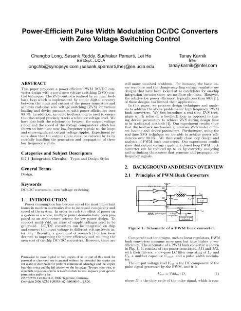
Figure 1: Schematic of a PWM buck converter.<br />
Compared to other designs, such as linear regulators, PWM<br />
buck converters consume more area but have higher power<br />
efficiency. The schematic of a PWM buck converter is shown<br />
in Fig. 1. It consists of two power transistors, M1 and M2,<br />
with their drivers, a low-pass LC filter consisting of L f and<br />
C f , a snubber capacitor C snub , and a pulse width modulator.<br />
The output voltage level V out is the <strong>DC</strong> component of the<br />
pulse signal generated by the PWM, and it is<br />
load<br />
V ref<br />
V out = V dd in · D, (1)<br />
where D is the duty cycle of the pulse signal, which is con-
−<br />
+<br />
+<br />
−<br />
trolled by V ref as an input of the PWM. In fact,<br />
Therefore, we have<br />
D =<br />
V ref<br />
V dd in<br />
. (2)<br />
V out = V ref . (3)<br />
As shown in [6], the output voltage ripple of a PWM buck<br />
converter can be expressed as<br />
∆V out =<br />
V ddin(1 − D)D<br />
8L f C f f 2 , (4)<br />
where L f and C f are the inductance and capacitance of the<br />
LC filter and f is the frequency of the pulse signal. f is also<br />
called the operation frequency of the buck converter.<br />
Equation (4) shows that to keep ∆V out at a low level, L f<br />
and/or C f has to be large if the operation frequency f is<br />
low. In other words, an effective way to reduce the area of<br />
the LC filter in the buck converter is to use a high operation<br />
frequency [2]. However, a high operation frequency leads to<br />
a high switching power loss. To reduce the switching power<br />
loss, a technique called zero voltage switch (ZVS) has been<br />
widely adopted.<br />
As shown in [4], ZVS ensures that both<br />
power transistors switch under a zero voltage drop between<br />
source and drain.<br />
2.2 Overview of the Proposed Topology<br />
input stage<br />
Input1<br />
CLK1<br />
Input2<br />
flip−flops<br />
CLK2<br />
RS<br />
latch<br />
Figure 3: Topology of the voltage comparator.<br />
3. CLOSE LOOP DESIGN AND ANALYSIS<br />
3.1 Analysis on output voltage ripple<br />
Original signal<br />
Average signal<br />
Residual signals<br />
D/2<br />
t2<br />
t1<br />
Duty cycle changes<br />
Vdd<br />
Vss<br />
Q<br />
Q<br />
T<br />
M1<br />
M2<br />
Vdd<br />
Vx<br />
Csnub<br />
Vhigh<br />
real−time ZVS control<br />
Vlow<br />
Lf<br />
Cf<br />
1 1<br />
D<br />
Vout<br />
Load<br />
Vref<br />
VC 1<br />
+<br />
−<br />
ZVS startup detection<br />
D<br />
1 1<br />
D<br />
Figure 2: Overview of the proposed circuit topology.<br />
Our study in this paper is based on the circuit topology<br />
shown in Figure 2. This circuit contains two feedback loops.<br />
The outer loop consists of two power transistors M 1 and M 2,<br />
LC filter L f and C f , voltage comparator V C1, RC integrator<br />
R i and C i, pulse modulation element V C2, and real-time<br />
ZVS circuitry. The inner loop starts from the output of the<br />
two power transistors, passes through the ZVS circuitry and<br />
ends at the input of the two power transistors.<br />
The outer loop ensures that the output voltage level V out<br />
tracks the reference voltage level V ref . It is considered a<br />
negative feedback loop since there are only one set of negative<br />
components, the power transistors, in the entire looop.<br />
For example, if V out is higher than V ref , the output of voltage<br />
comparator V C1 is high, C i is charged, and the voltage<br />
level at the positive input of V C2 is increased, which increases<br />
the duty cycle of the switching signal and therefore<br />
decreases V out.<br />
The design of voltage comparator is adopted from [7],<br />
which has shown high resolution and low power consumption.<br />
The topology of the voltage comparator is shown in<br />
Figure 3, which is composed by an input amplification stage,<br />
two flip flops and a RS latch. Two clock signals are used to<br />
clear up previous results and evaluations. More details are<br />
described in [7].<br />
The real-time ZVS technique is achieved by the inner feedback<br />
loop. To avoid the influence of startup strike, a detection<br />
sub-circuit is included as shown in Figure 2. The idea<br />
is not to startup the ZVS circuitry until V out has been stabilized.<br />
More details will be described in Section 4.<br />
Ri<br />
Ci<br />
D<br />
Vtri<br />
VC 2<br />
+<br />
−<br />
Vctrl<br />
Figure 4: Illustration of changes in duty cycle in the<br />
switching signal.<br />
Our study is based on the design shown in Figure 2. The<br />
voltage comparator V C 2 in the figure modulates the duty<br />
cycle of the switching signal feeding the two power transistors<br />
and this modulation introduces a signal that contains<br />
a wide range of frequencies. Low frequency components of<br />
this signal may pass the LC filter and cause a voltage ripple<br />
with a frequency approximately equal to the frequency of<br />
the LC filter,1/(2π p L f C f ), at the output terminal. Note<br />
that the voltage comparator V C 1 may also bring in low frequency<br />
components but it is filtered by the R iC i integrator<br />
and has a smaller impact to the overall output ripple.<br />
Figure 4 illustrates the behavior of the operating switching<br />
signal during steady state. In the figure, this signal is<br />
decomposed into an average signal, which maintains a constant<br />
duty cycle and a set of residual signals. The average<br />
signal contains only high frequency components, and the<br />
residual signals contain a wide range of frequency components.<br />
The duty cycle switches between two states D 1 and<br />
D 2 has a frequency the same as the output voltage ripple,<br />
which is roughly equal to frequency of the LC filter, i.e.,<br />
T = 2π p L f C f . (5)<br />
By Fourier transformation, the residual signals can be expressed<br />
as follows,<br />
f(t) = 2V ∞<br />
dd<br />
π<br />
[ X<br />
n=0<br />
∞X<br />
+ (<br />
n=0<br />
= 2V dd<br />
π<br />
≈ 2V dd<br />
π<br />
(<br />
sin(2n + 1)ωt2 − sin(2n + 1)ωt1<br />
)cos(2n + 1)ωt<br />
2n + 1<br />
cos(2n + 1)ωt1 − cos(2n + 1)ωt2<br />
)sin(2n + 1)ωt]<br />
2n + 1<br />
p ∞X 2 − 2cos(2n + 1)ω(t2 − t 1)<br />
cos((2n + 1)ωt + φ)<br />
2n + 1<br />
∞X<br />
ω(t 2 − t 1)cos((2n + 1)ωt + φ),<br />
n=0<br />
n=0
where<br />
ω =<br />
Notice that t 2 − t 1 = T · ∆D 2<br />
f(t) =<br />
V ddT<br />
π p L f C f<br />
∆D<br />
1<br />
p<br />
Lf C f<br />
. (6)<br />
, we have<br />
∞X<br />
cos((2n + 1)ωt + φ). (7)<br />
n=0<br />
From (6) we can see that ω is the 3db frequency of the<br />
LC filter which implies that the magnitude of a signal at<br />
this frequency becomes half when it passes through the LC<br />
filter. Also, equation (7) implies that the residual signals<br />
contain frequency components of ω, 3ω, · · · , etc and the<br />
magnitudes of these components are proportional to ∆D.<br />
Given that ω is the 3db frequency of the LC filter, when the<br />
residual signals enter into the LC filter, the low frequency<br />
components, such as ω, 3ω and 5ω, can pass through the<br />
LC filter with significant magnitudes and appear as a ripple<br />
at the output terminal. Because the magnitudes of the low<br />
frequency components of ω, 3ω and 5ω etc. are proportional<br />
to ∆D, the magnitude of the ripple is proportional to ∆D<br />
too. Practically every voltage comparator has a smallest<br />
value of ∆D. In slower voltage comparators this ∆D are<br />
generally larger than in faster comparators. Therefore, we<br />
suggest to use fast voltage comparators to avoid large ripple<br />
at the output.<br />
4. REAL-TIME ZVS TECHNIQUE<br />
4.1 Traditional ZVS techniques<br />
A representative traditional design-time ZVS technique<br />
without feedback is presented in [4]. To illustrate the ZVS<br />
conditions, each cycle of the internal switching signal is divided<br />
into four time fragments, T 1, T 2, T 3 and T 4 in the<br />
figure. During T 1 and T 3, the NMOS power transistor M 2<br />
and PMOS power transistor M 1 close, respectively. During<br />
T 2 and T 4, both transistors are open. These two time<br />
fragments are called deadtimes. V x drops to zero at the beginning<br />
of T 1 when M 2 starts to close. Also, V x reaches Vdd<br />
when M 1 starts to close. Thus, M 1 and M 2 switch at a zero<br />
voltage drop between the source and drain i.e, zero voltage<br />
switching. During T 2, the inductance current I Lf charges<br />
C snub and V x increases to V dd. Similarly during T 1, the<br />
inductance current I Lf discharges C snub and V x decreases<br />
to zero.<br />
One can see that the conditions to achieve ZVS are very<br />
restrictive. Parameters have to be re-tuned when loading<br />
current changes. Design-time ZVS techniques without feedback<br />
are vulnerable to variations of devices and loading.<br />
Vx<br />
Vm1<br />
Vm2<br />
I Lf<br />
T1<br />
T2<br />
T3<br />
Vm1<br />
Vm2<br />
Figure 6: Conditions to achieve zero voltage switching.<br />
T4<br />
T<br />
T<br />
T<br />
4.2 Real-time ZVS technique<br />
Assuming V ctrl as the control signal of the power transistors,<br />
without considering ZVS, the control signals for the<br />
PMOS power transistor, M 1, and NMOS power transistor,<br />
M 2, are the same as V ctrl , i.e.,<br />
V m1 = V m2 = V ctrl . (8)<br />
To achieve ZVS, V m1 and V m2 can be expressed as<br />
V m1 = V ctrl + V x, (9)<br />
and<br />
V m2 = V ctrl · V x, (10)<br />
where V x is the output voltage level of the power transistors.<br />
Equation (9) ensures that V m1 is 1 whenever V x is 0, which<br />
implies that M 1 turns on (V m1 changes from 1 to 0) only<br />
when V x is 1, i.e., the voltage drop between the source and<br />
drain of M 1 is zero. Similarly, (10) ensures that V m2 is<br />
0 whenever V x is 1, which implies that M 2 turns on (V m2<br />
changes from 0 to 1) only when V x is 0, i.e., the voltage drop<br />
between the source and drain of M 2 is zero.<br />
Equation (9) and (10) explain the principle to achieve<br />
ZVS. The implementation of this principle, however, needs<br />
more careful analysis. To ensure that V x stays at the perfect<br />
Vdd/zero level when M 1 and M 2 start to open, we use<br />
voltage comparators instead of inverters to implement V x<br />
as shown in Figure 2. To drive M 1, V x is compared with<br />
V high = V DD − ∆v and only when V x is is higher than<br />
V high M 1 can open. Similarly, to drive M 2, V x is compared<br />
with a low voltage level V low = ∆v and only when V x is lower<br />
than V low , M 2 can open. In order to reduce the overshoot on<br />
V x, we use a ∆v slightly larger than zero (0.3v). However,<br />
as shown in our experiment results, it is impossible to fully<br />
eliminate overshoot.<br />
Overall, the real-time ZVS scheme presented as part of<br />
this design is very unique in the fact that it does not rely on<br />
manually calculating the duty cycle delays for a particular<br />
design. Although there are designs that do automatic ZVS<br />
control, they do not meet the power and area requirements<br />
for on-chip high frequency applications [8, 9].<br />
4.3 ZVS startup detection<br />
Initially, when the circuit is cold started, there is a period<br />
of time where the output signals have abnormally large variation.<br />
During this startup period there is no need to turn<br />
on the automatic ZVS calibration control for the system. In<br />
order to avoid tuning ZVS during the startup period, a series<br />
of D flip-flops are used as delay elements to prevent the<br />
startup of the ZVS calibration scheme until after the initial<br />
transient spikes, as shown in Fig. 2.<br />
5. EXPERIMENT RESULTS<br />
5.1 Close loop design and analysis<br />
To verify the idea that the output voltage ripple is proportional<br />
to the smallest duty cycle change ∆D, we have<br />
implemented the voltage comparator, as in Figure 3, at two<br />
different clock rates. One voltage comparator operates at<br />
400MHz and the other at 1.6 GHz frequencies. We compare<br />
the output voltage ripple of the PWM buck converters implemented<br />
with these two comparators in Figure 5. Note<br />
that 130nm technology is used, the V dd voltage is 1.3 Volt,<br />
and the reference voltage level is 0.85 Volt. As shown in<br />
the figure, the voltage ripple of the 400 MHz comparator is<br />
about 11.7% as compared to the reference voltage, while the<br />
voltage ripple of the 1.6 GHz comparator is 2.9%. By increasing<br />
the frequency of the comparator by 4X, we notice a<br />
reduction in ripple by around 4X. These experiment results<br />
show that when designing the closed loop PWM buck converter,<br />
the elements of the closed loop need to be carefully<br />
considered so that the output voltage ripple is minimized.
Figure 5: Comparison of voltage ripple between buck converters implemented by a 0.4GHZ voltage comparator<br />
and 1.6GHz voltage comparator.<br />
(a) (b) (c)<br />
(d) (e) (f)<br />
Figure 7: Design-time ZVS under loading of 5 ohms (a), 10 ohms (b), and 50 ohms (c) and real-time ZVS<br />
with feedback loop under loading of 5 ohms (d), 10 ohms (e), and 50 ohms (f). (A) and (c) fails ZVS.<br />
5.2 ZVS control<br />
One of the strong points of the design presented in this<br />
paper is the fact that the power of the transistors is consistent<br />
over a multitude of loads. This is mainly due to the<br />
fact that there is a real-time ZVS control system established<br />
in the circuit.<br />
Figure 7 contains a comparison between design-time ZVS<br />
without feedback and real-time ZVS with feedback. In the<br />
case of the load of 5 and 50 ohms with design-time ZVS, one<br />
can see that the circuit is out of the ZVS mode of operation.<br />
With a load of 5 ohms, the C snub capacitor is charged too<br />
slow and the voltage of V x does not transition from the lower<br />
state to the higher state before the M 1 transistor switches<br />
on. On the other hand with a load of 50 ohms, the designtime<br />
ZVS circuit discharges the C snub too slowly and the<br />
circuit is in a non optimal energy efficiency state once again.<br />
The real-time circuit always stays in the ZVS mode of operation<br />
with the various loads. Although, there is an overshoot<br />
(refer to Section 4.2) for the real-time ZVS circuit, this does<br />
not affect the energy usage of the power transistors.<br />
Overall, not having a proper ZVS control system will<br />
cause problems in terms of power usage of the switch transistors.<br />
In terms of overall power efficiency of the circuit,<br />
both ZVS operation and the actual magnitude of the current<br />
through the load play significant roles. But our experiments<br />
show that if the proper load current is used with real-time<br />
ZVS, power efficiencies are greater than 90% consistently for<br />
various loads.<br />
6. CONCLUSION<br />
In this paper, we have designed a novel PWM circuit that<br />
can be used to provide a range of Vdd levels for a variety of<br />
loads by two feedback loops. With the use of an inner feedback<br />
loop between the output and input of the power transistors,<br />
we are able to ensure real-time zero voltage switching.<br />
This enables the reduction of power consumed by these<br />
transistors and achieves power efficiencies over 90% for a variety<br />
of loads. Also, an outer feedback loop is employed in<br />
the PWM circuit to track the reference voltage level. We<br />
show that this closed loop should be propriately modeled<br />
and designed to ensure a low output voltage ripple.<br />
7. REFERENCES<br />
[1] S. Rajapandian, Z. Xu, and K. Shepard, “Charge-recycling<br />
voltage domains for energy-efficient low-voltage operation of<br />
digital cmos circuits,” in Computer Design, 2003.<br />
Proceedings. 21st International Conference on, pp. 98–102,<br />
2003.<br />
[2] V. Kursan, S. G. Narendra, V. K. De, and E. G. Friedman,<br />
“Analysis of buck converters for on-chip integration with a<br />
dual supply voltage microprocessor,” IEEE Trans. VLSI<br />
Syst., vol. 11, pp. 514–522, June 2003.<br />
[3] G. Schrom, P. Hazucha, J.-H. Hahn, V. Kursun, D. Gardner,<br />
S. Narendra, T. Karnik, and V. De, “Feasibility of<br />
monolithic and 3d-stacked dc-dc converters for<br />
microprocessors in 90nm technology generation,” in Proc.<br />
Intl. Symp. Low <strong>Power</strong> Electronics and Design, pp. 263–268,<br />
2004.<br />
[4] A. J. Stratakos, S. R. Sanders, and R. W. Brodersen, “A<br />
low-voltage cmos dc-dc converter for a portable<br />
battery-operated system,” in <strong>Power</strong> Electronics Specialists<br />
Conference, PESC ’94 Record., 25th Annual IEEE,<br />
pp. 619–626, June 1994.<br />
[5] A. J. Stratakos, “High-efficiency low-voltage dc-dc<br />
conversion for portable applications,” PhD dissertation,<br />
University of California, Berkeley, 1998.<br />
[6] D. W. Hart, ed., Introduction to <strong>Power</strong> Electronics. Prentice<br />
Hall, Upper Saddle River, N.J., 1997.<br />
[7] G. Yin, F. Eynde, and W. Sansen, “A high-speed CMOS<br />
comparator with 8-b resolution,” IEEE Journal of<br />
Solid-state Circuits, vol. 27, pp. 208–211, Feb. 1992.<br />
[8] Y. Jang and M. Jovanovic, “A new zvs-pwm full-bridge<br />
converter,” in IEEE International Telecommunications<br />
Energy Conference, pp. 232–239, Septemeber 2002.<br />
[9] J. Cho, J. Sabate, G. Hua, and F. Lee, “Zero-voltage and<br />
zero-current-switching full bridge pwm converter for high<br />
power application,” in IEEE Transactions on <strong>Power</strong><br />
Electronics, pp. 102–108, May 1994.