
You also want an ePaper? Increase the reach of your titles
YUMPU automatically turns print PDFs into web optimized ePapers that Google loves.
CONTENTS<br />
1 INTRODUCTION ...................................................................................................................................... 3<br />
1.1 Why should we use profile (ribbed, corrugated/wavy) pipe .................................................................... 3<br />
1.2 Why polypropylene has been chosen as a material for the <strong>Pragma</strong> systems ........................................ 3<br />
1.3 Why the colour of the pipe system must be different from black ............................................................ 3<br />
2 APPENDIX ............................................................................................................................................... 3<br />
3 ADVANTAGES ......................................................................................................................................... 4<br />
4 STANDARDS ........................................................................................................................................... 5<br />
4.1 Why are standards necessary ................................................................................................................ 5<br />
4.2 Which standards the <strong>Pragma</strong> system should meet ................................................................................ 5<br />
4.3 What do the standards require ............................................................................................................... 5<br />
5 PRODUCT RANGE ................................................................................................................................. 8<br />
5.1 Sewage <strong>pipes</strong> PP-B <strong>Pragma</strong> ® SN>8 kN/m 2 , SN>10 kN/m 2 , SN>12 kN/m 2 , SN>16 kN/m 2 according to EN 13476-3 .. 8<br />
5.2 PP-B <strong>Pragma</strong> ® Fittings SN>8 kN/m2 according to standard EN 13476-3 ............................................... 8<br />
5.2.1 PP-B <strong>Pragma</strong> ® Socket ............................................................................................................................. 8<br />
5.2.2 PP-B <strong>Pragma</strong> ® Offset ............................................................................................................................... 9<br />
5.2.3 PP-B <strong>Pragma</strong> ® Joint ................................................................................................................................. 9<br />
5.2.4 PP-B <strong>Pragma</strong> ® Reducer ........................................................................................................................... 10<br />
5.2.5 PP-B <strong>Pragma</strong> ® Adaptor to PVC (for connecting of <strong>Pragma</strong> end without socket with an end with<br />
socket of PVC KG) ................................................................................................................................... 10<br />
5.2.6 PP-B <strong>Pragma</strong> ® Plug ................................................................................................................................. 10<br />
5.2.7 PP-B <strong>Pragma</strong> ® Sealing ring ..................................................................................................................... 10<br />
5.2.8 Assembly ring with a seal (for connecting of a PVC KG end without a socket with a <strong>Pragma</strong><br />
end with a socket) .................................................................................................................................... 10<br />
5.2.9 PP-B <strong>Pragma</strong> ® Saddle with a screw ........................................................................................................ 11<br />
5.2.10 A drilling crown for a saddle with a screw for tightening the screw .......................................................... 11<br />
5.2.11 A rubber muff for in-situ connection ......................................................................................................... 12<br />
5.2.12 A drilling crown for in-situ connection ....................................................................................................... 12<br />
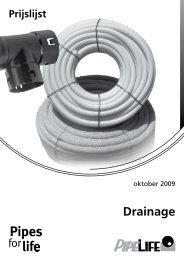
5.3 Drainage <strong>pipes</strong> PP-B <strong>Pragma</strong> ® SN>8 kN/m2 according to EN 13476-3 ...................................................... 12<br />
6 REQUIREMENTS FOR LAYING THE PRAGMA ® PIPE SYSTEM ......................................................... 13<br />
6.1 General assumptions ............................................................................................................................... 13<br />
6.2 Bedding conditions ................................................................................................................................... 13<br />
6.2.1 Bedding on natural ground ....................................................................................................................... 13<br />
6.2.2 Bedding on a foundation .......................................................................................................................... 13<br />
6.3 Sidefill, initial backfill and final backfill ...................................................................................................... 14<br />
6.3.1 Sidefill and initial backfill .......................................................................................................................... 14<br />
6.3.2 Degree of compaction .............................................................................................................................. 15<br />
6.3.3 Final backfill ............................................................................................................................................. 15<br />
6.3.4 Tamping of the embedment material ........................................................................................................ 15<br />
6.3.5 Trench width ............................................................................................................................................. 15<br />
6.3.6 Filling necessary for achieving the desired angle of laying ...................................................................... 15<br />
7 INSTALLATION OF PRAGMA ® PIPES ................................................................................................... 16<br />
7.1 Connection of <strong>Pragma</strong> ® - <strong>Pragma</strong> ® <strong>pipes</strong> ................................................................................................. 16<br />
7.2 Cutting of <strong>Pragma</strong> ® <strong>pipes</strong>. Mounting sealing ring ..................................................................................... 16<br />
7.3 Joining to the sewage collectors from <strong>Pragma</strong> ® <strong>pipes</strong> ................................................................................. 17<br />
7.4 Joining to PRO ® manholes ....................................................................................................................... 17<br />
7.5 Locking against pulling out of socket connection of <strong>Pragma</strong> ® DN/OD <strong>pipes</strong> ........................................... 18<br />
8 TRANSPORTATION, LOADING AND UNLOADING, STORAGE .......................................................... 20<br />
9 HYDARAULIC SCALING OF THE PRAGMA ® SYSTEM ....................................................................... 21<br />
9.1 General assumptions ............................................................................................................................... 21<br />
9.2 Governing formulas .................................................................................................................................. 21<br />
9.3 Software and scaling tables ..................................................................................................................... 22<br />
9.4 Hydraulic nomograph ............................................................................................................................... 22<br />
9.4.1 Nomograph for hydraulic scaling of circular <strong>pipes</strong> with a partially full profile ........................................... 22<br />
9.4.2 Nomograph for hydraulic scaling of non-pressure flow in circular <strong>Pragma</strong> ® <strong>pipes</strong> with a full profile ........ 23<br />
9.5 Slopes and velocities of flow in <strong>Pragma</strong> ® <strong>pipes</strong> slopes ............................................................................ 24<br />
10 STRESS AND STRENGTH ANALYSIS OF BURIED PRAGMA ® PIPES ............................................... 25<br />
10.1 Interaction between the pipe and the surrounding soil ............................................................................. 25<br />
10.2 Load ......................................................................................................................................................... 26<br />
10.3 Types of soils according to ENV 1046 ..................................................................................................... 27<br />
10.4 Necessary data for statistical calculation of the PRAGMA ® pipe system ................................................. 28<br />
Pipelife<br />
www.pipelife.com<br />
2
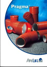
1 INTRODUCTION<br />
1.1 Why should we use profile (ribbed, corrugated/wavy) pipe<br />
The <strong>Pragma</strong> pipe systems are distinct with their specific structure of inner smooth layer and profile outer layer. This structure allows<br />
with a minimum expenditure of raw material, thus low weight, to be achieved high cross stiffness of the ring<br />
(SN>8 kN/m 2 , SN>10 kN/m 2 , SN>12 kN/m 2 , SN>16 kN/m 2 according to ISO 9969).<br />
SN – (nominal ring stiffness)<br />
What is unique about the structure is that it guarantees high ring elasticity and stability to dynamic and static pressure.<br />
1.2 Why polypropylene has been chosen as a material for the <strong>Pragma</strong> systems<br />
Polypropylene (PP-B) is the latest generation of thermoplastic materials which are used for the production of pipe systems. This material<br />
combines the stability of the polyvinylchloride (PVC) and the elasticity of the polypropylene. This makes it balanced and the most<br />
appropriate for meeting the complex requirements of EN 13476-3.<br />
1.3 Why the colour of the pipe system must be different from black<br />
The practice in the production of thermoplastic systems according to the coextrusion shows that the coloring of the ready products in<br />
black is determined by the fact that using secondary materials (scrap) makes technologically impossible the production of materials<br />
with a homogeneous color different from black.<br />
That is why Pipelife manufactures its products in a color different from black, proving once again irrefutably the usage of only primary<br />
raw materials.<br />
2 APPENDIX<br />
The <strong>Pragma</strong> system is designed for gravity take away of:<br />
● Household,<br />
● Production,<br />
● Rain,<br />
● Mixed and<br />
● Drainage<br />
waste waters<br />
<strong>Pragma</strong> system finds application also in:<br />
● • Electricity supply and<br />
● Telecommunication<br />
As a protective pipe system.<br />
Finds application in the building, yard and platform sewage systems.<br />
Pipelife<br />
www.pipelife.com<br />
3
3 ADVANTAGES<br />
● Resistance to abrasion<br />
● Chemical resistance (from pH=2 to pH=12)<br />
● Resistance to high temperatures (60°C at constant flow and from 95°C to 100°C at short-time flow)<br />
● Shock resistance – according to the requirements of EN 1411 and EN 12061<br />
● Guaranteed stiffnesses SN>8 kN/m 2 , SN>10 kN/m 2 , SN>12 kN/m 2 , SN>16 kN/m 2 for the <strong>pipes</strong> - according to the<br />
requirements of ISO 9969<br />
● Easy transportation<br />
● Fast and easy assembly<br />
● Easy cutting and cutting out<br />
● Matrix casted elastomeric gaskets EPDM 45 ± 5. EN 681-1<br />
● Guaranteed water tightness of the system from -0,3 bar to +0,5 bar according to the requirements of EN 1277<br />
● Low weight<br />
● Long exploitation life<br />
● Low ratio of hydraulic roughness - theoretical 0,0011 mm, exploitation 0,015 mm (local resistances are not included)<br />
● High hydraulic conductivity<br />
● A full range of connecting elements (fittings, manholes and tools)<br />
● Compatibility with smooth wall PVC <strong>pipes</strong> KG type by unique system of adaptors<br />
● An integrated part of the whole sewage system of <strong>pipes</strong>, fittings manholes and equipments<br />
● A bright inner surface for an easy inspection<br />
● Guaranteed resistance of the system to weak and loess soils<br />
● The <strong>pipes</strong> and the fittings are with an integrated ribbed socket and a elastomeric gasket<br />
● All the elements of the <strong>Pragma</strong> system are manufactured under a constant production control of the raw material and the<br />
ready product.<br />
4<br />
Pipelife<br />
www.pipelife.com
4 STANDARDS<br />
4.1 Why are standards necessary<br />
The standards are a combination of rules and norms based on practical and theoretical observations and research on technical parameters,<br />
which the products should meet. They define minimum requirements for quality of the specific product. At the same time<br />
they guarantee compatibility of products manufactured by different companies.<br />
All this makes the standard extremely important because it guarantees all the interested parties: designers, engineers, architects,<br />
builders, clients and control authorities that the product which is used meets the specific application and possesses all the qualities<br />
for unhindered, flawless and lasting exploitation.<br />
4.2 Which standards the <strong>Pragma</strong> system should meet<br />
The <strong>Pragma</strong> system is manufactured and meets the requirements of EN 13476-3:2008 Plastics piping systems for non-pressure<br />
underground drainage and sewage - Structured-wall piping systems of unplasticized poly(vinyl chloride) (PVC-U), polypropylene (PP)<br />
and polyethylene (PE) - Part 3: Requirements for <strong>pipes</strong> and connecting pats with smooth inner profile surface and for the systems<br />
“type B”.<br />
It is applicable to the active standards in our country for design of sewage systems: „EN 752:2008 Drain and sewage systems outside<br />
buildings” and „Norms for design of sewage systems” adopted by Order № RD-02-14-140 from 17. 04.1989, on the grounds of Art.<br />
201, par. 1 of local requirements, 9 and 10 from 1989, Amended, local requirement, 1 from 1993.<br />
4.3 What do the standards require<br />
The standard EN 13476-3:2008 orders minimum requirements for the profile pipe systems with regard to the following characteristics:<br />
► Ring stiffness. Tested according to EN ISO 9969:2007<br />
Minimum allowable stiffness:<br />
SN≥4 kN/m 2 - при DN ≤ 500 mm<br />
SN≥2 kN/m 2 - при DN > 500 mm<br />
Maximum allowable stiffness:<br />
SN≥16 kN/m 2<br />
► Ring flexibility. Tested according to EN ISO 13968:2008 (old EN 1446)<br />
The standard requires preserving the structure and elasticity of the material in case of ring deformation up to 30%.<br />
This requirement is difficult to achieve in the manufacture of profile <strong>pipes</strong> from PE due to the low module of elasticity and the bigger<br />
height of the rib, bigger pressure on the outer layer of the pipe and the occurrence of irreversible deformations.<br />
Pipelife<br />
www.pipelife.com<br />
5
POSITIVE RESULT<br />
Force F<br />
10% 20% 30% Deflection<br />
NEGATIVE RESULT<br />
Force F<br />
F max<br />
6<br />
10% 20% 30% Deflection<br />
► Creep ratio. Tested according to EN ISO 9967<br />
Creeping is a remaining deformation at the plastics as a result of the constantly applied external load. Creeping abates for a period of<br />
about two years. Creeping is crucial for the leak tightness of the socket connection.<br />
The standard requires that creep ratio for the PP and PE <strong>pipes</strong> to be < 4.<br />
Creep ratio is inversely proportional to the module of elasticity. The bigger the module of elasticity, the less is the creeping and vise<br />
versa.<br />
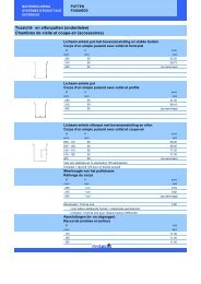
► Requirements for tolerances on <strong>pipes</strong>, connecting elements and systems. Tested according to EN 1852-1,<br />
PE EN12666-1<br />
The basic geometrical characteristics are included in EN 13476. The correct proportions and tolerances assure us that all elements of<br />
the system are the same, fit close to each other and allow a reliable assembly.<br />
This is crucial and important condition which concerns the connections with a elastomeric gasket. The proportions of the <strong>pipes</strong> and the<br />
fitting elements are determined according to their outer diameter DN/OD or their inner diameter DN/ID. Standard EN 13476 defines<br />
the following nominal diameters:<br />
DN/ID [mm]: 100, 125, 150, 200, 225, 250, 300, 400, 500, 600, 800, 1000, 1200<br />
DN/OD [mm]: 110, 125, 160, 200, 250, 315, 400, 500, 630, 800, 1000, 1200<br />
According to the diameter, the standard defines the wall thickness of the <strong>pipes</strong> smooth ends, the sockets and their inner layers as<br />
well as the length of any product. The tolerances mentioned in the standard describe mainly and only a limit value namely minimal<br />
and maximal.<br />
► Impact resistance. Tested according to EN 744, EN 1411, EN 12061<br />
This test checks if the <strong>pipes</strong> and the fitting elements won’t be damaged during transportation, storage and assembly.<br />
According to the standard EN 13476-part 2 and 3, there is only one requirement: TIR < 10% at temperature 0°С.<br />
The point of damage is assessed as a real impact (dynamically active) norm [TIR - true impact rate] for a shipment or production<br />
where the maximum value for TIR is 10% [TIR=the total number of damages divided by the total number of impacts, as a percentage,<br />
as if the whole shipment was tested].<br />
Pipelife<br />
www.pipelife.com
► leak-tightness of elastomeric sealing ring type joints (spigot socket). Tested according to EN 1277<br />
This method tests the system’s ability to retain liquids from and out of the system (filtration/infiltration). The test also confirms the<br />
connection between the smooth end the elastomeric sealing ring and the socket. The density of the system concerns the ecological<br />
aspect of soil and water protection.<br />
The standard requires leak tightness of the connections<br />
of - 0,3 bar negative pressure<br />
up to + 0,5 bar positive pressure.<br />
The connections are tested in extreme conditions, including connections with an angle and diametrical declination of the ring from<br />
negative to positive state. For the rain and sewage pipe systems this is one of the fundamental characteristics.<br />
► Mechanical strength or flexibility of fabricated fittings. Tested according to EN 12256<br />
The standard defines the mechanical strength of the fittings and requires if a particular force (F), on a particular length (L) of the fitting,<br />
the shift (A) to remain within 170 mm without destruction of the fitting solidity at a critical point (C).<br />
A<br />
B<br />
C<br />
shift<br />
connection<br />
critical point<br />
Nominal diameter<br />
DN/OD 1)<br />
mm<br />
Minimal<br />
moment<br />
kN.m (FxL)<br />
Minimal shift<br />
mm (A)<br />
110 0,20 170<br />
125 0,29 170<br />
160 0,61 170<br />
200 1,20 170<br />
250 2,30 170<br />
315 3,10 170<br />
355 3,50 170<br />
400 4,00 170<br />
450 4,50 170<br />
500 5,00 170<br />
630 6,30 170<br />
710 7,10 170<br />
800 8,00 170<br />
900 9,00 170<br />
1000 10,00 170<br />
1) For DN/ID fittings the test is conducted by using the parameters, specified<br />
for the next bigger DN/OD diameter, instead of the outer diameter of<br />
the particular DN/ID diameter<br />
► Resistance to high temperatures. Tested according to EN 1437 and EN 1055.<br />
During the exploitation the thermoplastic pipe systems for drainage and household sewage must be resistant to specific temperatures<br />
of the waste waters. Due to this, the systems made of thermoplastics, must be resistant to the following temperatures when they are<br />
laid in soil and out of the buildings.<br />
According to the empiric requirements of TEPPFA (The European Plastic Pipes and Fittings Association) they are the following:<br />
lasting water temperature of 45°С for dimensions ≤ 200 мм<br />
lasting water temperature of 35°С for dimensions >200 мм<br />
Due to the fact that this type of pipe systems are allowed to be buried in basements or installed at a distance of 1 m around the buildings,<br />
they must be resistant to maximal short-term flows waste water with a temperature of up to 95°С.<br />
Pipelife<br />
www.pipelife.com<br />
7
5 PRODUCT RANGE<br />
5.1 PP-B <strong>Pragma</strong> ® Sewage <strong>pipes</strong> SN>8 kN/m 2 , SN>10 kN/m 2 , SN>12 kN/m 2 ,<br />
SN>16 kN/m 2 according to EN 13476-3<br />
L<br />
H<br />
DN/OD – nominal outer (relative) diameter according to which the pipe or the fitting are manufactured<br />
DN/ID – nominal inner (relative) diameter according to which the pipe or the fitting are manufactured<br />
The <strong>pipes</strong> with diameters from DN/OD 160 up to DN/OD 400 are manufactured with a rotation welded socket. The <strong>pipes</strong> with diameters<br />
from DN/ID 500 up to DN/ID 1000 are manufactured with a coextruded socket, reinforced with a patented glass-reinforced<br />
plastic band in the zone of the rubber sealing.<br />
When there is a special inquiry, the following <strong>pipes</strong> can be delivered:<br />
5.2 PP-B <strong>Pragma</strong> ® Fittings SN>8 kN/m 2 according to EN 13476-3<br />
5.2.1 PP-B <strong>Pragma</strong> ® Socket<br />
<strong>Pragma</strong> ® sliding repair socket<br />
8<br />
Nominal<br />
diameter<br />
DN<br />
[mm]<br />
Outer<br />
diameter<br />
D out<br />
[mm]<br />
Inner<br />
diameter<br />
D in<br />
[mm]<br />
DN<br />
[mm]<br />
Rib’s height<br />
H<br />
D out<br />
[mm]<br />
[mm]<br />
L<br />
[mm]<br />
Rib’s length<br />
L<br />
[mm]<br />
Product<br />
code<br />
DN/OD160 169,90 190 PRU160<br />
DN/OD200 213,60 230 PRU200<br />
DN/OD250 266,90 261 PRU250<br />
DN/OD315 336,20 303 PRU315<br />
DN/OD400 426,90 325 PRU400<br />
DN/ID500 624,00 345 PRU+ID500<br />
DN/ID600 750,00 400 PRU+ID600<br />
DN/ID800 997,00 528 PRU+ID800<br />
Pipe’s<br />
length<br />
(without<br />
socket)<br />
[m]<br />
Socket<br />
length<br />
[mm]<br />
Inner<br />
socket<br />
diameter<br />
D in socket<br />
[mm]<br />
<strong>Pragma</strong> ® connecting double socket<br />
DN<br />
[mm]<br />
D out<br />
[mm]<br />
Product code<br />
DN/OD 160 160 139,0 10,50 18,33 6 94 160,5 PRAGMA160/6<br />
DN/OD 200 200 176,0 12,00 20,63 6 113 201,9 PRAGMA200/6<br />
DN/OD 250 250 221,3 14,35 20,63 6 129 252,4 PRAGMA250/6<br />
DN/OD 315 315 277,4 18,80 27,50 6 148 318,0 PRAGMA315/6<br />
DN/OD 400 400 350,0 25,00 33,00 6 158 403,7 PRAGMA400/6<br />
DN/ID 500 573 498,0 36,50 60,95 6 246 577 PRAGMA500+ID/6<br />
DN/ID 600 688 597,0 44,00 69,65 6 289 693 PRAGMA600+ID/6<br />
DN/ID 800 925,2 799,0 61,10 81,26 6 339 931,8 PRAGMA800+ID/6<br />
DN/ID 1000 1140,4 1000,0 70,20 121,89 6 403 1148,4 PRAGMA1000+ID/6<br />
Nominal<br />
diameter<br />
DN<br />
[mm]<br />
Outer<br />
diameter<br />
D out<br />
[mm]<br />
Inner<br />
diameter<br />
D in<br />
[mm]<br />
Rib’s height<br />
H<br />
[mm]<br />
Rib’s length<br />
L<br />
[mm]<br />
Pipe’s<br />
length<br />
(without<br />
socket)<br />
[m]<br />
Socket<br />
length<br />
[mm]<br />
Inner<br />
socket<br />
diameter<br />
D in socket<br />
[mm]<br />
Product code<br />
DN/ID 200 228,4 195 14,0 26,0 6 118,2 230,5 PRAGMA200+ID/6<br />
DN/ID 250 284,9 245 17,2 28,9 6 126,6 287,6 PRAGMA250+ID/6<br />
DN/ID 300 343 299 21,6 34,7 6 116 346,4 PRAGMA300+ID/6<br />
DN/ID 400 458 398 28,9 43,5 6 139 462 PRAGMA400+ID/6<br />
DN/OD 500 500 436,8 31,6 43,23 6 188 504,6 PRAGMA500/6<br />
DN/OD 630 630 550,1 39,95 49,41 6 232 635,8 PRAGMA630/6<br />
L<br />
[mm]<br />
Product<br />
code<br />
DN/OD160 169,90 190 PRH160<br />
DN/OD200 213,60 230 PRH200<br />
DN/OD250 266,90 261 PRH250<br />
DN/OD315 336,20 303 PRH315<br />
DN/OD400 426,90 325 PRH400<br />
DN/ID500 624,00 345 PRH+ID500<br />
DN/ID600 750,00 400 PRH+ID600<br />
DN/ID800 997,00 528 PRH+ID800<br />
DN/ID1000 1174 806 PRH+ID1000<br />
Pipelife<br />
www.pipelife.com
5.2.2 PP-B <strong>Pragma</strong> ® Bend<br />
Z1<br />
Z 2<br />
A<br />
α<br />
DN<br />
[mm]<br />
D out<br />
[mm]<br />
α<br />
(°)<br />
Z 1<br />
[mm]<br />
Z 2<br />
[mm]<br />
t<br />
[mm]<br />
A<br />
[mm]<br />
Product<br />
code<br />
DN/OD160 169,90 15 110 21 97 110 PRB160x15°<br />
DN/OD160 169,90 30 121 31 97 108 PRB160x30°<br />
DN/OD160 169,90 45 149 41 97 116 PRB160x45°<br />
DN/OD200 213,60 15 134 23 116 119 PRB200x15°<br />
DN/OD200 213,60 30 159 176 113 132 PRB200x30°<br />
DN/OD200 213,60 45 158 48 116 119 PRB200x45°<br />
DN/OD200 213,60 90 442 459 113 132 PRB200x90°<br />
DN/OD250 266,90 15 186 161 129 170 PRB250x15°<br />
DN/OD250 266,90 30 203 178 129 170 PRB250x30°<br />
DN/OD250 266,90 45 287 261 129 170 PRB250x45°<br />
DN/OD250 266,90 90 459 434 129 170 PRB250x90°<br />
DN/OD315 336,20 15 197 169 148 176 PRB315x15°<br />
DN/OD315 336,20 30 218 217 148 176 PRB315x30°<br />
DN/OD315 336,20 45 320 320 148 176 PRB315x45°<br />
DN/OD315 336,20 90 533 533 148 176 PRB315x90°<br />
DN/OD400 426,90 15 222 220 158 196 PRB400x15°<br />
DN/OD400 426,90 30 250 248 158 196 PRB400x30°<br />
DN/OD400 426,90 45 366 363 158 196 PRB400x45°<br />
DN/OD400 426,90 90 615 613 158 196 PRB400x90°<br />
DN/ID500 624,00 15 447 450 170 202 PRB+ID500xαº<br />
DN/ID600 750,00<br />
30<br />
45<br />
563 541 197 243 PRB+ID600xαº<br />
DN/ID800 997,00 90<br />
247 PRB+ID800xαº<br />
5.2.3 PP-B <strong>Pragma</strong> ® Branch<br />
DN<br />
[mm]<br />
d y<br />
[mm]<br />
D 1<br />
[mm]<br />
d e<br />
[mm]<br />
Z 1<br />
[mm]<br />
Z 2<br />
[mm]<br />
t<br />
[mm]<br />
t 1<br />
[mm]<br />
A<br />
[mm]<br />
Product<br />
code<br />
DN/OD160 DN/OD110 292 183 97 73 110 PREA160/110x45°<br />
169,90 160<br />
DN/OD160 DN/OD160 347 214 97 97 108 PREA160/160x45°<br />
DN/OD200 DN/OD160 372 231 116 97 121 PREA200/160x45°<br />
213,60 200<br />
DN/OD200 DN/OD200 417 264 116 116 121 PREA200/200x45°<br />
DN/OD250 DN/OD160 457 456 134 97 140 PREA250/160x45°<br />
266,90 250<br />
DN/OD250 DN/OD200 457 300 134 116 140 PREA250/200x45°<br />
DN/OD315 DN/OD160 484 494 146 97 154 PREA315/160x45°<br />
DN/OD315 336,20 DN/OD200 315 484 338 146 116 154 PREA315/200x45°<br />
DN/OD315 DN/OD250 744 360 146 124 154 PREA315/250x45°<br />
DN/OD400 DN/OD160 660 458 158 94 198 PREA400/160x45°<br />
DN/OD400 DN/OD200 726 491 158 113 198 PREA400/200x45°<br />
426,90<br />
400<br />
DN/OD400 DN/OD250 793 411 158 124 198 PREA400/250x45°<br />
DN/OD400 DN/OD315 892 446 158 130 198 PREA400/315x45°<br />
DN/ID500<br />
DN/OD160 751 300 97 PREA+ID500/160x45°<br />
DN/ID500 DN/OD200 809 340 116 PREA+ID500/200x45°<br />
DN/ID500 624,00 DN/OD250 573 983 500 170 124 262 PREA+ID500/250x45°<br />
DN/ID500 DN/OD315 983 500 116 PREA+ID500/315x45°<br />
DN/ID500 DN/OD400 1098 640 139 PREA+ID500/400x45°<br />
DN/ID600<br />
DN/OD160 751 300 97 PREA+ID600/160x45°<br />
DN/ID600 DN/OD200 809 340 116 PREA+ID600/200x45°<br />
DN/ID600 DN/OD250 983 500 124 PREA+ID600/250x45°<br />
750,00<br />
688<br />
197<br />
DN/ID600 DN/OD315 983 500 116 PREA+ID600/315x45°<br />
DN/ID600 DN/OD400 1098 640 139 PREA+ID600/400x45°<br />
DN/ID600 DN/ID500 PREA+ID600/500x45°<br />
Pipelife<br />
www.pipelife.com<br />
9
5.2.4 PP-B <strong>Pragma</strong> ® Reducer<br />
5.2.5 PP-B <strong>Pragma</strong> ® Adapter to PVC (for connecting of <strong>Pragma</strong> end without a socket with a PVC KG<br />
end with a socket)<br />
DN<br />
[mm]<br />
d e<br />
[mm]<br />
d i<br />
[mm]<br />
d 1<br />
[mm]<br />
Z 1<br />
[mm]<br />
М<br />
[mm]<br />
t<br />
[mm]<br />
L<br />
[mm]<br />
Product<br />
code<br />
DN/OD200 200 176,0 DN/OD160 123 30 97 250 PRR200/160<br />
DN/OD250 250 221,3 DN/OD200 176 49 188 413 PRR250/200<br />
DN/OD315 315 277,4 DN/OD200 180 144 203 527 PRR315/200<br />
DN/OD315 315 277,4 DN/OD250 180 57 124 361 PRR315/250<br />
DN/OD400 400 350,0 DN/OD250 190 165 124 479 PRR400/250<br />
DN/OD400 400 350,0 DN/OD315 190 71 130 391 PRR400/315<br />
DN/ID500 573 498,0 DN/ID400 173 254 139 566 PRR+ID500/400<br />
DN/ID600 688 597,0 DN/ID400 208 300 139 647 PRR+ID600/400<br />
DN/ID600 688 597,0 DN/ID500 208 72 170 450 PRR+ID600/500<br />
DN<br />
[mm]<br />
М<br />
[mm]<br />
А<br />
[mm]<br />
L<br />
[mm]<br />
Product code<br />
DN/OD160 80 84 168 PRP160<br />
DN/OD200 102 100 208 PRR200<br />
DN/OD250 124 145 326 PRR250<br />
DN/OD315 130 163 361 PRR315<br />
DN/OD400 141 184 409 PRR400<br />
5.2.6 PP-B <strong>Pragma</strong> ® Plug<br />
DN<br />
[mm]<br />
Product code<br />
DN/OD 160 PRM 160<br />
DN/OD 200 PRM 200<br />
DN/OD 250 PRM 250<br />
DN/OD 315 PRM 315<br />
DN/OD 400 PRM 400<br />
DN/ID 500 PRM +ID 500<br />
DN/ID 600 PRM +ID 600<br />
5.2.7 PP-B <strong>Pragma</strong> ® Sealing ring<br />
EPDM 45 +/-5 – ethylene propylene diene monomer<br />
5.2.8 PP-B <strong>Pragma</strong> ® Assembly ring with a seal (for connecting of PVC KG end without a socket with<br />
10<br />
a <strong>Pragma</strong> end with a socket)<br />
DN<br />
[mm]<br />
Material Product code<br />
DN/OD 160 EPDM PRK 160<br />
DN/OD 200 EPDM PRK 200<br />
DN/OD 250 EPDM PRK 250<br />
DN/OD 315 EPDM PRK 315<br />
DN/OD 400 EPDM PRK 400<br />
DN/ID 500 EPDM PRK +ID 500<br />
DN/ID 600 EPDM PRK +ID 600<br />
DN/ID 800 EPDM PRK +ID 800<br />
DN/ID 1000 EPDM PRK +ID 1000<br />
DN<br />
[mm]<br />
Product code<br />
DN/OD 160 PRS 160<br />
DN/OD 200 PRS 200<br />
DN/OD 250 PRS 250<br />
DN/OD 315 PRS 315<br />
DN/OD 400 PRS 400<br />
Pipelife<br />
www.pipelife.com
5.2.9 PP-B <strong>Pragma</strong> ® Saddle with a screw<br />
The saddle with a screw is designed for connecting of building<br />
sewage declinations of PVC-U to <strong>Pragma</strong> ® <strong>pipes</strong> already<br />
in exploitation. In case that the building sewage declination is<br />
from <strong>Pragma</strong> ® <strong>pipes</strong> it is necessary to use an extra <strong>Pragma</strong> ®<br />
PRP adaptor to PVC (see 5.2.5). The saddle with a screw<br />
contains a saddle – a bended surface with the diameter of<br />
the pipe, a rubber sealing and a socket with a screw. With the<br />
tightening of the screw, the screw expands and the saddle<br />
is fixed to the pipe as a leak-tight connection is established.<br />
“Saddle with a screw” is manufactured in two types:<br />
● with a short socket for side connection to the pipe<br />
● with a socket for vertical connection – it is used to<br />
avoid the pressure of the vertically connected pipe to the saddle.<br />
The unique construction plays the role of a compensator<br />
in the range of up to 6 см.<br />
h2<br />
d<br />
A<br />
D<br />
h1<br />
D<br />
d D 1) min h 1 h 2 A<br />
[mm] [mm] [mm] [mm] [mm] [mm]<br />
Product code<br />
DN/OD 250 DN/OD 160<br />
116 170 168 PRLATIN160/250<br />
DN/OD 315 DN/OD 160 116 170 168 PRLATIN160/315<br />
DN/OD 400 DN/OD 160 116 170 168 PRLATIN160/400<br />
DN/OD<br />
DN/ID 500 DN/OD 160 116 170 168 PRLATIN160/500<br />
250<br />
DN/ID 600 DN/OD 160 116 170 168 PRLATIN160/600<br />
DN/ID 700 DN/OD 160 270 270 168 PRLATIN160/700<br />
DN/ID 800 DN/OD 160 270 270 168 PRLATIN160/800<br />
DN/ID 1000 DN/OD 160 270 270 168 PRLATIN160/1000<br />
DN/OD 315 DN/OD 200<br />
320 320 208 PRLATIN200/315<br />
DN/OD 400 DN/OD 200 320 320 208 PRLATIN200/400<br />
DN/ID 500 DN/OD 200 DN/OD 320 320 208 PRLATIN200/500<br />
DN/ID 600 DN/OD 200 315 320 320 208 PRLATIN200/600<br />
DN/ID 700 DN/OD 200 320 320 208 PRLATIN200/700<br />
DN/ID 800 DN/OD 200 320 320 208 PRLATIN200/800<br />
DN/ID 1000 DN/OD 200 320 320 208 PRLATIN200/1000<br />
1) Minimal nominal diameter of the pipe where the opening<br />
is made.<br />
Assembly instructions<br />
1. Make an opening in the pipe with a drilling crown<br />
2. Clean the opening with a knife<br />
3. Place the saddle tightly in the opening<br />
4. Put a lubricant to the screw and to the socket seal<br />
5. Tighten the screw with a wrench<br />
5.2.10 A drilling crown with a screw and a wrench for tightening the screw<br />
For inlet<br />
[mm]<br />
D<br />
[mm]<br />
H<br />
[mm]<br />
d<br />
[mm]<br />
Product code<br />
DN/OD 160 168 65 12 PRLATDRILL160<br />
DN/OD 200 200 80 13 PRLATDRILL200<br />
D<br />
[mm]<br />
Product code<br />
160 PRLATKEY160<br />
200 PRLATKEY200<br />
Pipelife<br />
www.pipelife.com<br />
11
5.2.11 A rubber muff for in-situ connection<br />
ID<br />
L<br />
OD<br />
For inlet<br />
[mm]<br />
OD<br />
[mm]<br />
ID<br />
[mm]<br />
L<br />
[mm]<br />
D 1) min<br />
[mm]<br />
D 2) max<br />
[mm]<br />
Product<br />
code<br />
DN/OD 110 136 110 51 DN/OD 200<br />
PRMAN110<br />
DN/OD 160 186 160 51 DN/OD 250 PRMAN160<br />
DN/ID<br />
DN/OD 200 226 200 51 DN/OD 315 PRMAN200<br />
800<br />
DN/OD 250 276 250 51 DN/OD 400 PRMAN250<br />
DN/OD 315 341 315 51 DN/OD 500 PRMAN315<br />
1) Minimal nominal diameter of the pipe in which the opening is made<br />
2) Maximal nominal diameter of the pipe in which the opening is made<br />
The additional contacts to the extension elements to for manholes (PRO type) and to <strong>pipes</strong> (PVC-KG и <strong>Pragma</strong> ® ) with a big diameter<br />
can be done by in-situ connection as the nominal diameter of the connection is from DN/OD110 to DN/OD315.<br />
Assembly instructions<br />
1. Make an opening in the pipe with a drilling crown<br />
2. Clean the opening with a knife<br />
3. Put the rubber muff tightly in the opening<br />
The rubber muff is designed for a direct connection of a smooth wall PVC KG pipe. If the connection will be made with a corrugated<br />
pipe <strong>Pragma</strong> ® type it is necessary to mount a PRP adaptor from <strong>Pragma</strong> ® to PVC (see 5.2.5).<br />
5.2.12 A drilling crown for in-situ connection<br />
For inlet D H<br />
[mm] [mm] [mm]<br />
DN/OD 110 138 100<br />
d<br />
[mm]<br />
Product code<br />
PRFREZ110<br />
DN/OD 160 184 100 PRFREZ160<br />
DN/OD 200 225 100 13 PRFREZ200<br />
DN/OD 250 275 150 PRFREZ250<br />
DN/OD 315 340 150 PRFREZ315<br />
5.3 PP-B <strong>Pragma</strong> ® drainage <strong>pipes</strong> SN≥8 kN/m 2 according to EN 13476-3<br />
d y<br />
DN/OD<br />
L 1<br />
d i<br />
d e<br />
DN/OD di de dy t L1 L Perforation<br />
type<br />
[mm] [mm] [mm] [mm] [mm] [mm] [m]<br />
Product code<br />
160 139 160 184 94 140 6,0<br />
PRAGMADR160/6-220g<br />
200 174 200 227 113 162 6,0 PRAGMADR200/6-220g<br />
250 218 250 283 129 185 6,0 LP PRAGMADR250/6-220g<br />
315 276 315 355 148 211 6,0 PRAGMADR315/6-220g<br />
400 348 400 451 158 251 6,0 PRAGMADR400/6-220g<br />
t<br />
L<br />
*Face of perforation for all <strong>pipes</strong> > 50 cm 2 /m<br />
The <strong>pipes</strong> are manufactured with a welded socket. The <strong>Pragma</strong> ® drainage <strong>pipes</strong> are totally compatible with the fittings of the sewer<br />
<strong>pipes</strong> <strong>Pragma</strong> ® DN/OD – nominal diameter.<br />
If the client requires, can be delivered <strong>pipes</strong> with a TP or MP perforation type.<br />
AT/99-02-0752-02 COBRTI INSTAL<br />
AT/2003-04-0506 IBDiM<br />
PN/EN 13476-3<br />
DIN 4262-1<br />
Perforation types<br />
certificate GIG Nr 4265058-12<br />
certificate Kiwa Denmark BRL 9208<br />
Pipelife<br />
www.pipelife.com<br />
12
6 REQUIREMENTS FOR LAYING THE PRAGMA ® PIPE SYSTEM<br />
6.1 General assumptions<br />
The most important factor for achieving<br />
a satisfactory assembly of a plastic container<br />
is the interaction between the pipe<br />
and the surrounding soil. A bigger pipe’s<br />
resistance value is achieved by the soil<br />
in the pipe’s zone. Therefore the type of<br />
the backfill and the degree of sealing in<br />
the pipe’s zone are of great importance.<br />
Hence in every sewage project the engineer<br />
must determine the laying conditions<br />
like:<br />
6.2 Bedding conditions<br />
The bedding design depends on the soil<br />
geotechnical characteristics of the zone<br />
in which the sewer pipe is to be laid. In<br />
general two methods of pipe bedding<br />
can be considered:<br />
1. Conditions of the existing soil layers<br />
and fitness for their usage for trench basis<br />
and backfill.<br />
2. Geotechnical characteristics of the<br />
soil used for bedding layer as well as the<br />
way they are performed.<br />
3. Appropriate class of pipe’s stiffness.<br />
At the beginning of every project, the<br />
first step is to be made a geotechnical<br />
research of the layers in which the pipe<br />
- natural bedding on the native undisturbed<br />
ground;<br />
- bedding on the foundation made of<br />
selected soil material, compacted to the<br />
required level.<br />
will be laid. This research as well as the<br />
lab tests must be made with regard to the<br />
establishment of soil type and its structure,<br />
the degree of sealing and the level<br />
of the underground waters.<br />
6.2.1 Bedding on natural ground<br />
In some instances, it may be acceptable<br />
to lay <strong>Pragma</strong> pipe on the bottom of<br />
the trench, but only in granular, dry soil<br />
which is free of large stones (>20 mm),<br />
such as gravel, coarse sand, fine sand<br />
and sandy clay)<br />
In such soil conditions, the pipe is laid<br />
on the thin (10 to 15 cm), uncompacted<br />
bedding directly underneath the pipe.<br />
The purpose of the bedding is to bring<br />
the trench bottom up to the grade and to<br />
provide a firm, stable and uniform invert<br />
support of minimum 90º angle (see fig.<br />
6.1)<br />
Figure 6.1 Laying in natural conditions<br />
6.2.2 Bedding on a foundation<br />
There are situations where a pipeline<br />
should be laid on a foundation. These<br />
include:<br />
● natural bedding on the native undisturbed<br />
ground;<br />
● bedding on a foundation made of<br />
selected soil material, compacted to the<br />
required level.<br />
There are situations where a pipeline<br />
should be laid on a foundation. These<br />
include:<br />
1. when in favourable natural ground<br />
conditions, the trench is mistakenly overcut<br />
to a depth below the designed pipe<br />
level;<br />
2. in rocky soils, cohesive soils (clays)<br />
and silty soils;<br />
3. in weak, soft soils, such as organic<br />
silts and peat;<br />
Pipelife<br />
www.pipelife.com<br />
4. in any other conditions where the<br />
project document requires a foundation.<br />
An example of the solution for cases 1<br />
and 2 is presented in Figure 5.2. The<br />
pipeline is laid on two layers made of<br />
sandy soils or gravel soils with maximum<br />
size of 20 mm.<br />
● The foundation layer is made of well<br />
compacted soil of thickness 25 cm (minimum<br />
15 cm).<br />
● The bedding layer is 10 to 15 cm<br />
thick, uncompacted.<br />
In the case of weak soils, depending on<br />
the thickness of the weak soil layer below<br />
the designed pipeline level, two solutions<br />
can be applied.<br />
1. Where the thickness of the weak soil<br />
layer is ≤ 1.0 m (see fig. 6.3).<br />
In this case, the weak soil is removed and<br />
the trench is filled with a well-compacted<br />
layer of a broken stone and sand mixture<br />
(volume ratio 1:0.3) or a broken stone<br />
and sand mixture (volume ratio 1:0.6).<br />
The foundation is laid on a geotextile.<br />
2. Where the thickness of the weak soil<br />
layer is > 1.0 m (see fig. 6.3).<br />
In this case, a 25 cm thick foundation<br />
made of a well-compacted layer of a<br />
gravel and sand mixture (volume ratio<br />
1:3) or a broken stone and sand mixture<br />
(volume ratio 1:0.6) laid on a geotextile is<br />
recommended<br />
13
Figure 6.2 An example for laying in resistant<br />
soil<br />
Figure 6.3 An example for laying in<br />
weak soil (loess) depth ≤ 1.0 m<br />
In all cаses the sealing of the founding<br />
layer must be from 85% up to 95% according<br />
to Proctor<br />
Figure. 6.4 An example for laying in<br />
weak soil (loess) > 1.0 m<br />
0 – additional 25 cm founding layer<br />
from crushed gravel and sand or from natural<br />
gravel and crushed gravel<br />
1 – founding layer from crushed gravel<br />
and sand or from natural gravel and sand<br />
2 – bedding layer<br />
3 – geotextile<br />
6.3 Sidefill, initial backfill and final backfill<br />
Apart from a proper foundation and bedding, the soil class and density realised in the sidefill (haunching) and initial backfill are important<br />
factors in achieving a satisfactory installation of a flexible pipeline.<br />
6.3.1 Sidefill and initial backfill<br />
The criteria to select material as suitable<br />
to use as fill in the haunching zone (sidefill)<br />
and directly above the crown of the<br />
pipe (initial backfill) are based on achieving<br />
adequate soil strength and stiffness<br />
after compaction. Suitable soil material<br />
includes most graded, natural granular<br />
materials with maximum particle size not<br />
exceeding 10% of the nominal pipe diameter<br />
or 60 mm, whichever is smaller.<br />
The fill material should not contain foreign<br />
matter such as snow, ice or frozen<br />
earth clumps.<br />
Figure 6.5 Pipeline section<br />
a – main backfill<br />
b – cover depth<br />
c – pipe zone<br />
d – bedding (if required)<br />
e – foundation (if required)<br />
Table 3.1 Characteristics of the<br />
materials for covering around<br />
the pipe and backfill<br />
COVERING AROUND THE PIPE’S ZONE AND FOLLOWING BECKFILL<br />
Material<br />
Gravel,<br />
Crushed stones<br />
Particles diameter<br />
[mm]<br />
8-22, 4-16<br />
8-12, 4-8<br />
Gravel 2-20<br />
Sand,<br />
Moraine gravel<br />
0.2-20<br />
Notes<br />
The most appropriate soil material, maximum<br />
5 to 20% particles with size of 2 mm<br />
Appropriate soil material, maximum, 5 to 20%<br />
particles with size of 0,2 mm<br />
Relatively appropriate soil material, maximum 5%<br />
particles with size of 0,02 mm<br />
Pipelife<br />
www.pipelife.com<br />
14
6.3.2 Degree of compaction<br />
The required degree of fill compaction<br />
depends on loading conditions.<br />
● In paved areas, the minimum soil<br />
compaction in the pipe zone is 90% of<br />
modified Proctor test density.<br />
● Outside of paved areas, the fill<br />
should be compacted to:<br />
6.3.3 Final backfill<br />
The material used for completing the<br />
backfilling can be made with excavated<br />
material if suitable to achieve the required<br />
project compaction and can have<br />
maximum particle size of 300 mm.<br />
- 85% of modified Proctor test density if<br />
the depth of cover is < 4.0 m;<br />
- 90% of modified Proctor test density if<br />
the depth of cover is ≤ 4.0 m.<br />
The fill material should be compacted to<br />
layers of 10 to 30 cm in thickness.<br />
The thickness of the initial backfill over<br />
For pipelines of diameter D < 400 mm<br />
and with an initial backfill thickness of 15<br />
cm, the final backfill material should not<br />
contain particles of size > 60 mm.<br />
In paved areas, the minimum compacthe<br />
crown of the pipe should be:<br />
● minimum 15 cm for a pipe of diameter<br />
D < 400 mm;<br />
● minimum 30 cm for a pipe of diameter<br />
D ≤ 400 mm.<br />
tion of the final backfill should be 90% of<br />
modified Proctor test density.<br />
6.3.4 Tamping of the embedment material<br />
The requirements for the degree of sealing<br />
depend on the general load and must<br />
be defined in the design documentation.<br />
The tamping must be made with different<br />
types of tamping. Depending on the<br />
equipment, the layers’ thickness and<br />
the soil susceptibility, different results of<br />
sealing can be achieved. Table 3.2 gives<br />
data which are related to gravel, sand<br />
clay and alluvium soils.<br />
Equipment<br />
Weight<br />
[kg]<br />
Maximal layer’s<br />
thickness before<br />
compaction [m]<br />
gravel,<br />
sand<br />
COMPACTION METHODS<br />
loam, clay,<br />
silt<br />
Maximal<br />
thickness<br />
of the initial<br />
backfill above<br />
pipe<br />
[m]*<br />
Number of passes to obtain compaction<br />
85%<br />
modified<br />
Proctor test<br />
90%<br />
modified<br />
Proctor test<br />
95%<br />
modified<br />
Proctor test<br />
Close treading - 0.10 - - 1 3 6<br />
Hand tamping min. 15 0.15 0.10 0.30 1 3 6<br />
Vibrating tamper 50-100 0.30 0.20-0.25 0.50 1 3 6<br />
Table 3.2 Compaction methods<br />
Separated<br />
vibrating plates **<br />
Vibrating plate<br />
50-100 0,20 - 0.50 1 4 7<br />
50-100<br />
100-200<br />
400-600<br />
-<br />
-<br />
0.20<br />
* before compacting equipment is used<br />
** to compact the soil on both sides of the pipe<br />
0.50<br />
0.40<br />
0.80<br />
1<br />
1<br />
1<br />
4<br />
4<br />
4<br />
7<br />
7<br />
7<br />
6.3.5 Trench width<br />
The width of the trench should enable the proper placement and compaction of the fill material. The minimum width of the sidefill is<br />
b min =30 cm. Thus, the minimum width of the trench (B) at the top of the pipe is:<br />
B = D + (2 x b min )<br />
If the stiffness of the native undisturbed ground is lower than the stiffness of the designed fill, the trench width (B) should be:<br />
(in general, this condition deals with <strong>pipes</strong> in diameter dn > 250 mm because for <strong>pipes</strong> of smaller diameter the trench width (B) fills<br />
this condition)<br />
B ≥ 4 x d n<br />
Such situations can take place in granular soils of low density (I D < 0.33) or in cohesive soils of plastic limit I L > 0.0.<br />
6.3.6 Filling necessary for achieving the desired angle of laying<br />
Pipelife<br />
www.pipelife.com<br />
D out<br />
DN<br />
[mm]<br />
D out<br />
[mm]<br />
Angle of laying 2α<br />
60° 90° 120° 180°<br />
h 2α [cm]<br />
DN/OD160 160 1 2 4 8<br />
DN/OD200 200 1 3 5 10<br />
DN/OD250 250 2 4 6 12<br />
DN/OD315 315 2 5 8 16<br />
DN/OD400 400 3 6 10 20<br />
DN/ID500 573 4 8 14 29<br />
DN/ID600 688 5 10 17 34<br />
DN/ID800 925,2 6 14 23 46<br />
DN/ID1000 1140,4 8 17 28 57<br />
15
7 INSTALLATION OF PRAGMA ® PIPES<br />
7.1 Connection of <strong>Pragma</strong> ® <strong>pipes</strong><br />
PP-B <strong>Pragma</strong> ® pipe PP-B <strong>Pragma</strong> ® branch PP-B <strong>Pragma</strong> ® pipe<br />
PP-B <strong>Pragma</strong> ® pipe<br />
PP-B <strong>Pragma</strong> ®<br />
assembly with a seal<br />
PVC pipe with smooth walls<br />
PVC pipe with smooth walls<br />
PP-B <strong>Pragma</strong> ®<br />
Adaptor to PVC Pipe<br />
PP-B <strong>Pragma</strong> ® pipe<br />
7.2 Cutting of <strong>Pragma</strong> ® <strong>pipes</strong>. Mounting sealing ring<br />
●<br />
Cut pipe in the corrugation valley,<br />
using a fine tooth carpente’s saw.<br />
●<br />
sealing ring in the first plane<br />
between the ribs.<br />
Pipelife<br />
www.pipelife.com<br />
16
7.3 Joining to the sewage collectors from <strong>Pragma</strong> ® <strong>pipes</strong><br />
Joining to the sewage collectors made by <strong>Pragma</strong> ® <strong>pipes</strong> ia made by two ways:<br />
● Joining by a branch and a bend (see 5.2.2 and 5.2.3). It is recommended when joining to newly-laid collector which is still not<br />
in exploitation.<br />
● Joining by a saddle with a screw or with an in-situ connection (see 5.2.9 and 5.2.11). It is recommended when joining to an<br />
existing collector which is in exploitation.<br />
● In both cases it is recommended joining to be in the upper third of the collector’s section at an angle φ to the collector’s vertical<br />
axis. According to the position of the collector and the joining sewer to each other there are three main types:<br />
Figure 7.1 Joining of side sewer to a collector<br />
Figure 7.2 Joining of side sewer to a collector in case of displacement<br />
Figure 7.3 Joining of side sewer to a collector in case of displacement and an obstacle<br />
7.4 Joining to PRO ® manholes<br />
The PRO® manholes are designed and manufactured for suitable and safe joining to the pipe’s fittings of the <strong>Pragma</strong> ® series.<br />
For more details see the Pipelife catalogue for PRO ® manholes<br />
Pipelife<br />
www.pipelife.com<br />
17
7.5 Locking against pulling out of socket connection of <strong>Pragma</strong> ® DN/OD <strong>pipes</strong><br />
In practice <strong>pipes</strong> are buried in unfavorable soil conditions – loess, landslides, expansive soils which can lead to dislocation of the bed<br />
of the already buried <strong>pipes</strong>. In case of mass construction of infrastructure sewerage, structured-wall <strong>pipes</strong> with socket connection<br />
with rubber sealing are used. Under these conditions there is a risk of socket pulling out and respectively leak-tightness loss and soil<br />
contamination. Nevertheless, it is possible, due to carelessness in work during the backfill, the pipe not to be tight well and when the<br />
trench and the bed are not cultivated and stabilized the risk of pulling out is increased.<br />
That is why Pipelife Bulgaria decided to offer a simple and effective tool for locking the socket connection which practically guarantees<br />
its protection against pulling out.<br />
On the Figures below can be seen the different elements, necessary for this type of connection, the <strong>pipes</strong> prepared for assembly and<br />
the final result – <strong>Pragma</strong> locked socket connection.<br />
Figure 7.4 Necessary Elements For The Locked Socket Connection<br />
1. Socket End Of <strong>Pragma</strong> Pipe;<br />
2. EPDM Sealing Ring;<br />
3. EPDM Sealing Ring Turned Opposite To The Direction Of Pushing The Smooth End In The Socket End;<br />
4. Smooth End Of <strong>Pragma</strong> Pipe;<br />
5. EPDM Sealing Ring With “Click-Ring” Assembly Ring;<br />
6. “Click-Ring” Assembly Ring;<br />
18<br />
Pipelife<br />
www.pipelife.com
Figure 7.5 Pipes Ready For Assembly<br />
Figure 7.6 <strong>Pragma</strong> Locked Socket Connection<br />
Figure 7.7 <strong>Pragma</strong> Locked Socket Connection – Detailed View<br />
You must bear in mind that the additional elements necessary for locking of socket connection (on the Figures they are with numbers<br />
3, 5 and 6 while their description is given under Figure 7.4) are part of the standard <strong>Pragma</strong> product. They are available goods, kept<br />
in stock and practically they lead to an insignificant raise in the cost but at the same time they contribute to the securing of the socket<br />
connection against pulling out. The assembly can be made by any normal fitter because it doesn’t require any special skills or tools.<br />
The locking of the socket connection is applicable for <strong>Pragma</strong> DN/OD160, DN/OD200, DN/OD250, DN/OD315 and DN/OD400 <strong>pipes</strong>,<br />
on one hand because the necessary assembly “Click Ring” is manufactured for these series, on the other hand the <strong>Pragma</strong> DN/ID500,<br />
DN/ID600, DN/ID800 and DN/ID1000 <strong>pipes</strong> having bigger diameters are heavier, respectively their own weight protects them from<br />
pulling out of the socket connection.<br />
The sphere of application of the locked socket connection includes the above-mentioned loess soils, expansive soils, landslides and<br />
cases of strict assembly requirements – for example drainage systems for sanitary depots.<br />
Once made, the locked socket connection is practically impossible to disassemble therefore the fitters and the designers must consider<br />
its need and application carefully.<br />
Pipelife<br />
www.pipelife.com<br />
19
8 TRANSPORTATION, LOADING AND UNLOADING, STORAGE<br />
The wrong transportation (as well as the wrong storage) can lead to deformation or to damaging of the <strong>pipes</strong>, the fitting parts and the<br />
sealing rings with can eventually cause problems when laying and functioning of the already assembled <strong>pipes</strong>.<br />
For transportation must be used vehicles with a flat and clean loading surface e.g. without roughnesses for example protruding nails.<br />
The <strong>pipes</strong> can stick up (height) up to the five times the nominal diameter of the pipe. The <strong>pipes</strong> must lay along their length on the floor<br />
(see Fig. 8.1).<br />
Harsh lifting and dropping of the <strong>pipes</strong> must be avoided when loaded and unloaded. Their throwing when manually unloaded is<br />
inadmissible (see Fig. 8.4). For mechanized loading and unloading of packed <strong>pipes</strong> must be used appropriate transportation lifting<br />
vehicles like motor truck with a wide working surface or a crane.<br />
The <strong>pipes</strong> must be stored on flat surface and the allowed height is from 2.0 [m] up to 3.0 [m] (for <strong>pipes</strong> in pallets). For storing of free<br />
<strong>pipes</strong> the allowed height is up to 1.0 [m]. A two-way aligning is recommended during transportation and storage – on two adjacent<br />
rows the ends with sockets (respectively without sockets) must be pointed at different directions (see Fig. 8.5). Thus the load between<br />
the different rows is more uniform and placing of additional wooden supports is avoided. The wooden supports are placed only under<br />
the lowest row. The pipe must lay at least on three wooden supports each with a minimal width of 10 [cm].<br />
The <strong>Pragma</strong> pipe system can be stored outside. They are resistant to UV rays minimum two years as they retain their physicalmachanical<br />
qualities unchanged, regardless of the color change.<br />
Correct<br />
Wrong<br />
Transportation<br />
Figure 8.1 Figure 8.2<br />
Unloading<br />
Figure 8.3 Figure 8.4<br />
Storage<br />
Figure 8.5<br />
Pipelife<br />
www.pipelife.com<br />
20
9 HYDARAULIC SCALING OF THE PRAGMA ® SYSTEM<br />
9.1 General assumptions<br />
A hydraulic design concerns selecting<br />
parameters for gravity flow sewers,<br />
which normally do no flow full. The objective<br />
of hydraulic design is to determine<br />
the most economic pipe diameter at<br />
which the required discharge is passed.<br />
In practice, computation of hydraulic pipe<br />
parameters are based on the following<br />
9.2 Governing formula<br />
In practice, for computational purposes,<br />
the following semi-empirical equations<br />
are used:<br />
assumptions:<br />
1. The assumption of a uniform flow,<br />
meaning:<br />
● the depth (h), flow area (f) and velocity<br />
(v) at every cross-section remain<br />
constant at the whole considered pipe<br />
section;<br />
● the energy grade line, water surface<br />
and pipe bottom slope are parallel.<br />
2. In the pipe system, the flow regime is<br />
turbulent.<br />
where:<br />
Q – flow rate, [m 3 /s]<br />
V – average flow Velocity, [m/s]<br />
F – flow area, [m 2 ]<br />
Motion resistance on the pipe lenght<br />
are calculated based on unitary hydraulic<br />
gradient. Unitary hydraulic gradient<br />
for closed <strong>pipes</strong> with a settled turbulent<br />
motion is calculated based on Darcy-<br />
Weisbach formula:<br />
Hydraulic resistance coefficient (λ) is<br />
calculated based on Colebrook-White<br />
formula:<br />
where:<br />
i – unitary losses for conquering a friction<br />
resistance equal to slope of a pipe<br />
bottom with a free surface of water, [m/m]<br />
d – inner diameter of the pipe, [m]<br />
V – average flow velocity, [m/s]<br />
g – acceleration of gravity, [m/s 2 ]<br />
λ – linear resistance coefficient<br />
Re – Reynold number<br />
ν – coefficient of kinematic viscosity, [m 2 /s]<br />
(for water at temp 10°C ν = 1,308x10 -6 [m 2 /s])<br />
k – coefficient of absolut roughness, [mm]<br />
The Bretting formula for <strong>pipes</strong> flowing<br />
partly full:<br />
where:<br />
Q – flow rate in the pipe flowing full, [m 3 /s]<br />
q п – flow rate in the pipe flowing partly<br />
full, [m 3 /s]<br />
h п – actual depth of flow, [m]<br />
d – inner diameter of the pipe, [m]<br />
Ratio of absolute pipe wall – k, [mm]<br />
Laboratory roughness<br />
Pipe’s roughness in exploitation (without regard of the local resistance)<br />
Artificially bigger roughness the local resistances at the main sewage collectors<br />
Artificially bigger roughness with regard to the local resistances at secondary sewage collectors<br />
0,0011 [mm]<br />
0,015 [mm]<br />
0,25 [mm]<br />
0,40 [mm]<br />
The values of the artificially bigger roughness are recommended but not compulsory. The designers can choose another artificially<br />
bigger value of K or another method for calculation of local resistances.<br />
Pipelife<br />
www.pipelife.com<br />
21
9.3 Software and scaling tables<br />
Besides the following nomographs Pipelife offers to the designers other helpful tools for hydraulic scaling. In the “For the designer”<br />
section in www.pipelife.bg can be found and used a web software for hydraulic calculation of a particular sewage section, a software<br />
for hydraulic calculation of the sewage network and scaling tables for filling h/D=0.5, h/D=0.7 и h/D=1.0<br />
9.4 Hydraulic nomographs<br />
9.4.1 A nomograph for hydraulic scaling of circular <strong>pipes</strong> with partially full profile<br />
correlation between the flow depth and the pipe’s diameter (d)<br />
correlation between the actual flow with filling (h n ) and outflow for full profile<br />
correlation between the actual velocity with filling (h n ) and velocity for full profile<br />
correlation between the hydraulic radius with filling (h n ) and hydraulic radius for full profile<br />
Pipelife<br />
www.pipelife.com<br />
22
9.4.2 Nomographs for hydraulic scaling of non-pressure flow in circular <strong>Pragma</strong> ® <strong>pipes</strong> with a full profile<br />
For k = 0.015 [mm], water temperature t = 10°C, full profile<br />
Darcy-Weisbach/Colebrook-White Formula<br />
0,1<br />
Quantity Q [L/s]<br />
1 10 100 1000 10000<br />
0.4 m/s<br />
0.1 m/s<br />
0.15 m/s 0.25 m/s<br />
0.65 m/s<br />
1.0 m/s<br />
velocity V -[m/s]<br />
hydraulic slope [m/km]<br />
1<br />
1.6 m/s<br />
2.5 m/s<br />
10<br />
4.0 m/s<br />
6.5 m/s<br />
10.0 m/s<br />
100<br />
<strong>Pragma</strong> diameter [mm]<br />
For k = 0.25 [mm], water temperature t = 10°C, full profile<br />
Darcy-Weisbach/Colebrook-White Formula<br />
0,1<br />
Quantity -Q[L/s]<br />
1 10 100 1000 10000<br />
0.1 m/s<br />
0.4 m/s<br />
0.15 m/s 0.25 m/s<br />
0.65 m/s<br />
1.0 m/s<br />
hydraulic slope [m/km]<br />
1<br />
velocity V - [m/s]<br />
1.6 m/s<br />
2.5 m/s<br />
10<br />
4.0 m/s<br />
6.5 m/s<br />
10.0 m/s<br />
100<br />
<strong>Pragma</strong> diameter [mm]<br />
Pipelife<br />
www.pipelife.com<br />
23
For k = 0.40 [mm], water temperature t = 10°C, full profile<br />
Darcy-Weisbach/Colebrook-White Formula<br />
Quantity<br />
velocity<br />
hydraulic slope<br />
<strong>Pragma</strong> diameter [mm]<br />
9.5 Slopes and velocities of flow in PRAGMA ® <strong>pipes</strong> slopes<br />
The slope of the channel must also be<br />
considered as variable, since it is not<br />
necessarily completely defined by topo<br />
graphic conditions.<br />
The minimum channel slope is required<br />
to achieve the lowest flow velocity which<br />
will prevent suspended solids from settling<br />
out and clogging the pipe.<br />
In general, solid particles, e.g. sand particles,<br />
can deposit on the bottom to a<br />
depth corresponding to the particle friction<br />
angle (see Figure 9.1), expressed as<br />
where:<br />
hn – depth of flow, [m]<br />
d – inside pipe diameter, [m]<br />
Θ - internal friction angle, [°]<br />
If Θ = 35°<br />
then hn/d = 0,1<br />
The area of deposition may be allowed to<br />
a relatively flat zone of the channel bottom.<br />
Figure 9.1.<br />
Angle of friction<br />
The safe lower limit of velocity to avoid<br />
sedimentation depends on the type of<br />
sediments. Usually, the permissible minimum<br />
velocities (V sc ) which ensure selfcleaning<br />
of the channel should not be, at<br />
full flow, lower than:<br />
V sc = 0,8 m/s for sanitary sewers<br />
V sc = 0,6 m/s for storm sewers<br />
V sc = 1,0 m/s for combined sewers<br />
Pipelife<br />
www.pipelife.com<br />
24
When determining the slope of the pipeline,<br />
one should select the permissible<br />
velocities taking into account the pipe<br />
diameter. To this end, a simple formula<br />
can be used: 6)<br />
where:<br />
i min = minimum permissible slope<br />
d = internal pipe diameter<br />
The minimum slope of the sewer pipeline<br />
can also be expressed by the tractive<br />
force (t), given as: 7)<br />
where:<br />
γ = specific weight of waste water, [kg/m 3 ]<br />
R = hydraulic radius, [m]<br />
i = hydraulic slope, [m/m]<br />
The actual tractive force is: 8)<br />
From the above, the critical tractive force<br />
for the actual depth of flow (hn) is: 9)<br />
where:<br />
hidraulic radius for circual full<br />
flow pipe<br />
k 1 = correction factor,<br />
The critical tractive force which fulfil the<br />
condition of the channel self-cleaning is:<br />
10)<br />
(for storm water)<br />
(for sewage)<br />
Thus, from Equation 9, after rearranging,<br />
the minimum slope of the pipe is: 10a)<br />
(for storm water)<br />
(for sewage)<br />
10 STATIC SCALING OF PRAGMA ® SYSTEM<br />
10.1 Interaction between the pipe and the surrounding soil<br />
From the technical point of view, the<br />
plastic <strong>Pragma</strong> pipe is a flexible structure<br />
having a high ability to take up stress<br />
without failing. The classical method to<br />
evaluate the strength of a structural material<br />
is to describe the actual relation<br />
between the stress and the strain when<br />
the material is loaded. A vertical load imposed<br />
on the pipe causes a deflection<br />
(δ V ), a reduction in the vertical diameter<br />
of the flexible pipe, which takes causes<br />
it to take an elliptical shape (see Figure<br />
10.1)<br />
Figure 10.1 Deflection of<br />
circular pipe due to<br />
vertical load<br />
Deflection of the pipe causes bending stress<br />
in the pipe wall and exerts pressure on the<br />
surrounding soil, and the passive earth pressure<br />
decreases the bending stress in the<br />
pipe wall. The bending stress in the pipe wall<br />
caused by deflection is in momentary balance<br />
with the soil pressure acting against the outside<br />
of the pipe wall. The force the of the soil<br />
counteracting the pipe pressure depends on<br />
the vertical load, soil type and stiffness (density)<br />
in the pipe zone and on the pipe stiffness.<br />
For rigid <strong>pipes</strong> such as concrete, etc., the pipe<br />
alone has taken the main vertical forces acting<br />
on the pipe, while flexible pipe makes use of<br />
the horizontally acting soil support exerted as<br />
a result of the pipe deflection. Consequently,<br />
for the flexible pipe, the integration between<br />
the soil and the pipe has to be considered<br />
far more extensively than in the case of rigid<br />
<strong>pipes</strong>.<br />
a<br />
Figure 10.2<br />
b<br />
Pipelife<br />
www.pipelife.com<br />
25
The design concept of flexible <strong>pipes</strong> can<br />
be explained with the classical Spangler<br />
formula: 11)<br />
where:<br />
δv – deflection of the pipe diameter<br />
D – initial underformed pipe diameter<br />
q – vertical load<br />
SN – pipe ring stiffness<br />
S s – soil stiffness<br />
Equation (11) describes the relative deflection<br />
of a pipe subjected to a vertical<br />
load (q v ) supported by the pipe ring stiffness<br />
and the soil stiffness. This equation<br />
clearly shows that pipe deflection can<br />
be limited to the permissible magnitude<br />
by increasing one or both of the two factors,<br />
pipe ring stiffness and soil stiffness<br />
10.2 Load<br />
The soil pressure distribution for the<br />
Scandinavian Method [by Janson, Molin<br />
1991] is shown in Figure 10.3. The buried<br />
pipe is loaded with vertical load (q v ),<br />
which causes stress and strain, and with<br />
the counteracting horizontal load (q h ).<br />
in the pipe zone. Additionally, it can be<br />
said that pipe with greater ring stiffness is<br />
less subjected to interaction with the soil<br />
and is less dependent on the soil density<br />
in the pipe zone. Whereas application of<br />
a suitable enbedment of properly compacted<br />
material (higher cost of installation)<br />
enables the use of <strong>pipes</strong> of lower<br />
ring stiffness (lower in cost), in making a<br />
decision both the engineering and economic<br />
advantages of the alter-natives<br />
must be considered.<br />
VERTICAL LOADS<br />
1. Load due to soil above the pipe: 12)<br />
For <strong>pipes</strong> below the water table, the total<br />
pressure shall be increased with the hydrostatic<br />
pressure: 13)<br />
In this case, vertical load is: 14)<br />
Under normal conditions of pipe installation,<br />
the vertical load (q v ) component is<br />
larger than the horizontal load (q h ) component.<br />
The difference (q v - q h ) causes<br />
a reduction of the vertical pipe diameter<br />
and an increase in the horizontal pipe<br />
diameter. The pipe side walls, when<br />
deforming, mobilise a passive earth<br />
pressure of a value depending on the<br />
imposed vertical load and on the ratio<br />
between the soil stiffness and pipe stiffness.<br />
This last is expressed as the pipe<br />
ring stiffness (SN).The components of<br />
load which are likely to be imposed on a<br />
pipe in the vertical plane are:<br />
● the effect of the soil above the pipe<br />
● the effect of loads superimposed on<br />
the surface of the ground, such as those<br />
from buildings, vehicle wheel loads, etc.<br />
Ground level<br />
Ground water level<br />
Figure 10.3 Scandinavian Model of soil<br />
pressure distribution<br />
where:<br />
for <strong>pipes</strong><br />
above the ground water table<br />
where:<br />
Figure 10.4 Geometry of buried pipe<br />
Pipelife<br />
www.pipelife.com<br />
26
10.3 Types of soils according to ENV 1046<br />
Type<br />
of soil<br />
Group<br />
of soils<br />
according<br />
to<br />
ATV127<br />
G1<br />
Soil group<br />
Typical name Symbol Distinguishing feature Examples<br />
Gravel with a single size<br />
Gravels with a different size of<br />
the particles, gravel-sand<br />
Gravels with the same size of the<br />
particles, gravel-sand<br />
Sand with a single size<br />
(GE)<br />
[GU]<br />
[GW]<br />
(GI) [GP]<br />
(SE)<br />
[SU]<br />
Steep soil particle size line, with<br />
predominant particles with the<br />
same size<br />
Incessant soil particle size line, a<br />
few soil particle size groups<br />
Steep soil particle size line, one<br />
or more soil particle size groups<br />
are missing<br />
Steep soil particle size line, one<br />
soil particle size group dominates<br />
Crushed stone, river and<br />
bank gravel, moraine,<br />
cinder, volcanic ash<br />
Sand from dunes and<br />
bottom alluvium, river<br />
sand<br />
Covering<br />
YES<br />
G<br />
r<br />
a<br />
v<br />
e<br />
l<br />
Sands with a different size of the<br />
particles, sand-gravel<br />
Sands with the same size of the<br />
particles, sand-gravel<br />
[SW]<br />
(SI) [SP]<br />
Steep soil particle size line, a few<br />
soil particle size groups<br />
Steep soil particle size line, one<br />
or more soil particle size groups<br />
are missing<br />
Moraine sand, bank<br />
sand, shore sand<br />
YES<br />
G2<br />
и<br />
G3<br />
Alluvium gravels, gravel-alluvium-sand<br />
with the same size of<br />
the particles<br />
Clay gravels, gravel-sand-clay<br />
with the same size of the particles<br />
Alluvium sands, sand-alluvium<br />
with the same size of the particles<br />
Clay sands, sand-clay with the<br />
same size of the particles<br />
(GU)<br />
[GM]<br />
(GT)<br />
[GC]<br />
(SU)<br />
[SM]<br />
(ST)<br />
[SC]<br />
Wide/ soil particle size ine with<br />
interruptions with fine alluvium<br />
particles<br />
Wide/ soil particle size line with<br />
interruptions with fine alluvium<br />
particles<br />
Wide/ soil particle size line with<br />
interruptions with fine alluvium<br />
particles<br />
Wide/ soil particle size line with<br />
interruptions with fine alluvium<br />
particles<br />
Crashed gravel, beveled<br />
fragments, clay gravel<br />
Quick sand, sand loess<br />
Sand soil, alluvium clay,<br />
alluvium lime clay<br />
YES<br />
C<br />
ohesive<br />
O<br />
r<br />
g<br />
a<br />
n<br />
i<br />
c<br />
G4<br />
Nonorganic alluvium, fine sands,<br />
rock particles, alluvium or fine<br />
sands<br />
Nonorganic clay, plastic soil clay<br />
Soils with a mixed size of the<br />
particles and admixture of humus<br />
and talc<br />
Organic alluvium and organic<br />
alluvium clay<br />
Organic clay, clay with organic<br />
admixtures<br />
(UL)<br />
[ML]<br />
(TA)(TL)<br />
(TM)<br />
[CL]<br />
[OK]<br />
[OL](OU)<br />
[OH](OT)<br />
Low stability, short reaction, zero<br />
to weak plasticity<br />
Medium to high stability, slow<br />
reaction, low to medium plasticity<br />
Admixtures of plants / non-plant,<br />
rots, low weight, high porosity<br />
Medium stable, from slow to very<br />
fast reaction, low to medium<br />
plasticity<br />
High stability, zero reaction,<br />
medium to high plasticity<br />
Loess, clay<br />
Alluvium clay, clay<br />
Upper layers, hard sand<br />
Sea chalk, upper soil<br />
layer<br />
Mud, soil<br />
YES<br />
NO<br />
O<br />
r<br />
g<br />
a<br />
n<br />
i<br />
c<br />
Peat, others high organic soils<br />
Slime<br />
(HN)(H2)<br />
[Pt]<br />
[F]<br />
Non-homogenous peat, threadlike,<br />
colors from brown to black<br />
Slimes in the alluvium, often<br />
spreaded with sand / clay/talc,<br />
very soft<br />
Peat<br />
Slime<br />
NO<br />
Pipelife<br />
www.pipelife.com<br />
27
10.4 Necessary data for statistical calculation of the PRAGMA ® pipe system<br />
With regard to the correct laying and exploitation of the sewage <strong>pipes</strong> of the <strong>Pragma</strong> ® system it is important to calculate the impact<br />
of the static and the dynamic pressure. For this purpose it is necessary to take into account the soil’s type, the availability of subterranean<br />
waters, the degree of covering sealing according to Proctor. The calculation can be made with the Pipelife’s web software in<br />
the “For the designer” section” on www.pipelife.bg.<br />
Also Pipelife possesses a EASYPIPE software which if necessary can make more detailed calculated statistics of the laid <strong>pipes</strong>. Both<br />
programs are based on the methodology for statistical calculation of <strong>pipes</strong> laid in the ground according to ATV 127. For the preparation<br />
of this calculation by the Pipelife’s engineering team it is necessary to submit the following data:<br />
Project data<br />
Data about the soil<br />
around and in the<br />
excavation zone<br />
Project<br />
Client<br />
Designer<br />
Date<br />
Basic soil groups<br />
G1 - not connected<br />
G2 - weakly, slightly connected<br />
soils<br />
G3 - mixed connected<br />
soils, coarse, raw clay<br />
(blocked with slime, sand,<br />
sand with big particles<br />
and fine gravel, connected<br />
deposit stone soils)<br />
Zones (Figure 10.5)<br />
E1 E2 E3 E4<br />
Data about the<br />
pressure<br />
Surface<br />
G4 - connected (e.g. clay)<br />
h – Height of covering above the pipe’s crown, [m] (Figure 10.6)<br />
Soil’s density for covering, [kN/m 3 ]<br />
Additional static pressure (for example when storing), [kN/m 2 ]<br />
H w max – maximal level of subterranean waters above the pipe’s crown, [m] (Figure. 10.7)<br />
H w min – minimal level of subterranean waters above the pipe’s crown, [m] (Figure 10.7)<br />
Short-term internal pipe’s pressure, [bar]<br />
Long-term internal pipe’s pressure, [bar]<br />
Traffic pressure (mark one of the following cases)<br />
Traffic frequency<br />
Regularly Irregularly<br />
LT12 – 12 tons - 2 (semi)axes<br />
HT26 – 26 tons - 2 (semi)axes<br />
HT39 – 39 tons - 3 (semi)axes<br />
HT60 – 60 tons - 3 (semi)axes<br />
First layer<br />
Second layer<br />
Thickness<br />
h 1 , [m]<br />
Elasticity module<br />
E 1 , [MPa]<br />
Thickness<br />
h 2 , [m]<br />
Elasticity module<br />
E 2 , [MPa]<br />
Laying<br />
Embankment<br />
/<br />
Excavation<br />
Excavation width above the pipe’s crown - b (м) - (from 0,1 up to 20 м)<br />
Excavation angle of repose - β (degrees)<br />
Conditions of the excavation from group A1 A2 A3 A4<br />
A1 to A4 (see types of groups at the end)<br />
Conditions of the bedding layer fro group B1 B2 B3 B4<br />
B1 to B4 (see types of groups at the end)<br />
Type of bedding layer<br />
Angle of laying -2α<br />
60° 90° 120° 180°<br />
Sand cushion<br />
Concrete bedding layer<br />
Pipelife<br />
www.pipelife.com<br />
28
Е 3<br />
Е 2<br />
Е 4<br />
Е 1<br />
Е 2<br />
Е 3<br />
h<br />
Hw max<br />
Hw min<br />
Figure 10.5<br />
Figure 10.6<br />
Figure 10.7<br />
b<br />
h<br />
β<br />
2α<br />
Figure 10.8<br />
Figure 10.9<br />
Figure 10.10<br />
The “Cover Condition” (‘A1’ to ‘A4’) defines the method of securing and backfilling the trench from the pipe crown to the ground<br />
surface.<br />
A1 - Trench backfill compacted against the native soil by layers (without verification of compaction degree); applies also to pile walls.<br />
A2 - Vertical shuttering of the pipe trench using trench sheeting, which is not removed until after backfilling. Shuttering plates or equipment<br />
that are removed step by step during backfilling. Uncompacted trench backfill Washing-in of the backfill (suitable only for soils<br />
of group G1)<br />
A3 - Vertical shuttering of the pipe trench using sheet piling, lightweight piling profiles, wooden beams, shuttering plates or equipment<br />
which are not removed until after backfilling.<br />
A4 - Backfilling compacted in layers against the native soil with verification of the required compaction degree to ZTVE-StB (see Section<br />
4.2); applies also to beam pile walls (Berlin shuttering). Cover condition A4 is not applicable with soils of group G4.<br />
The “Bedding Condition” (‘B1’ to ‘B4’) describes the method of securing and backfilling the trench in the pipe zone (trench bottom<br />
up to pipe crown).<br />
B1 - Bedding compacted by layers against the native soil or in the embankment (without verification of the degree of compaction);<br />
applies also to beam pile walls.<br />
B2 - Vertical shuttering in the pipe zone using trench sheeting that reach down to the trench bottom and is not removed until after<br />
backfilling and compaction. Shuttering boards or equipment under the assumption that the soil is compacted after the trench sheeting<br />
is removed.<br />
B3 - Vertical shuttering within the pipe zone using sheet piling or lightweight piling profiles and compaction against the trench sheet<br />
reaching down below the trench bottom. There is no safe calculation model for determining vertical lining with wooden planks, boards<br />
or devices that are not removed until after backfilling and compacting the pipe zone.<br />
B4 - Bedding compacted by layers against the native soil or in the embankment with verification of the required compaction degree<br />
according to ZTVE-StB. Embedding condition B4 is not applicable with soils of group G4.<br />
Pipelife<br />
www.pipelife.com<br />
29