PE Pipe Technical Catalogue (PDF) - Pipelife Norge AS
PE Pipe Technical Catalogue (PDF) - Pipelife Norge AS
PE Pipe Technical Catalogue (PDF) - Pipelife Norge AS

You also want an ePaper? Increase the reach of your titles
YUMPU automatically turns print PDFs into web optimized ePapers that Google loves.
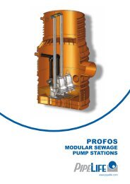
<strong>Pipe</strong>life <strong>Norge</strong> <strong>AS</strong><strong>Technical</strong> <strong>Catalogue</strong>for SubmarineInstallationsof Polyethylene <strong>Pipe</strong>s
<strong>Pipe</strong>life <strong>Norge</strong> <strong>AS</strong><strong>PE</strong> CATALOGUE-SUBMARINE APPLICATIONS, PI<strong>PE</strong>LIFE NORGE <strong>AS</strong>, December 2002.Table of content :0.0 INTRODUCTION.......................................................................................................... 40.1 DIFFERENT TY<strong>PE</strong>S OF SUBMARINE PI<strong>PE</strong>LINES ............................................................... 40.1.1 Intake pipeline......................................................................................................... 40.1.2 Transit pipeline........................................................................................................ 50.1.3 Outfall pipeline ........................................................................................................ 60.2 SINKING OF SUBMARINE <strong>PE</strong>-PI<strong>PE</strong>, EXAMPLE FROM A REAL PROJECT. (SEE ALSOSECTION A.5) ........................................................................................................................ 80.2.1 Introduction ............................................................................................................. 80.2.2 Sinking of the pipeline............................................................................................. 80.2.3 Installation of diffuser ............................................................................................ 120.2.4 Weather conditions ............................................................................................... 130.2.5 Summary .............................................................................................................. 13A. HYDRAULIC AND TECHNICAL DESIGN......................................................................... 15A.1 TECHNICAL DATA FOR DESIGN OF <strong>PE</strong>-PI<strong>PE</strong>LINES........................................................ 15A.2 HYDRAULIC DESIGN ................................................................................................. 18A.2.1 Coefficient of friction ............................................................................................. 18A.2.2 Coefficient for singular head losses ...................................................................... 20A.2.3 Density head loss.................................................................................................. 22A.2.4 Hydraulic capacity................................................................................................. 22A.2.5 Self cleaning velocity ............................................................................................ 25A.2.6 Air transport .......................................................................................................... 25A.3 STATIC DESIGN ....................................................................................................... 28A.3.1 Internal pressure................................................................................................... 28A.3.1.1HOOP DIRECTION................................................................................................................................28A.3.1.2 LONGITUDINAL DIRECTION ...................................................................................................................29A.3.2 External loads / buckling ....................................................................................... 31A.3.2.1BUCKLING OF UNSUPPORTED PI<strong>PE</strong>........................................................................................................32A.3.2.2 BUCKLING OF PI<strong>PE</strong> IN TRENCH / SOIL PRESSURE ....................................................................................35A.3.3 Water hammer ...................................................................................................... 36A.3.4 Temperature stresses ........................................................................................... 38A.3.5 Bending stresses .................................................................................................. 40A.3.5.1BUCKLING OF <strong>PE</strong> PI<strong>PE</strong> DURING BENDING...............................................................................................41A.3.6 Other stresses....................................................................................................... 43A.3.6.1 CURRENT AND WAVE FORCES ..............................................................................................................44A.3.6.2 HOVERING PI<strong>PE</strong>LINE............................................................................................................................45A.3.6.3 CONCENTRATED LOADS ......................................................................................................................45Side 2 av 84
<strong>Pipe</strong>life <strong>Norge</strong> <strong>AS</strong><strong>PE</strong> CATALOGUE-SUBMARINE APPLICATIONS, PI<strong>PE</strong>LIFE NORGE <strong>AS</strong>, December 2002.A.3.7 Combined loads.................................................................................................... 46A.4 DESIGN OF LOADING BY CONCRETE WEIGHTS ............................................................ 48A.4.1 Degree of loading.................................................................................................. 48A.4.2 Types of concrete weights .................................................................................... 50A.4.3 Stability of <strong>PE</strong>-pipeline on the seabed .................................................................. 51A.4.4 Recommended “air filling rate” for subwater pipelines .......................................... 54A.4.5 Current forces ....................................................................................................... 55A.4.6 Wave forces.......................................................................................................... 58A.5 DESIGN OF PARAMETERS FOR THE SINKING PROCESS................................................. 66A.5.1 Internal air pressure .............................................................................................. 67A.5.2 Pulling force .......................................................................................................... 67A.5.3 Sinking velocity ..................................................................................................... 71B. INSTALLATION......................................................................................................... 76B.1 JOINTING OF <strong>PE</strong> PI<strong>PE</strong>S ............................................................................................ 76B.2 BUTT FUSION OF <strong>PE</strong> PI<strong>PE</strong>S....................................................................................... 77B.2.1 Welding parameters.............................................................................................. 77B.2.2 Welding capacity................................................................................................... 78B.3 INSTALLATION......................................................................................................... 79B.3.1 Buried <strong>PE</strong> pipes .................................................................................................... 79B.3.2 <strong>Pipe</strong> laying on seabed........................................................................................... 81AUTHOR : TOM A. KARLSEN, INTERCONSULT <strong>AS</strong>A............................................................... 84LIST OF REFERENCES : ......................................................................................................... 84REFERENCE PROJECTS…..………………………………………………..………………...85Side 3 av 84
<strong>Pipe</strong>life <strong>Norge</strong> <strong>AS</strong><strong>PE</strong> CATALOGUE-SUBMARINE APPLICATIONS, PI<strong>PE</strong>LIFE NORGE <strong>AS</strong>, December 2002.0.0 IntroductionDescription of different types of submarine applications for polyethylene pipes.Submarine <strong>PE</strong>-pipes have been used for transport of drinking water and sewage water since 1960.The pipes were then produced in length of 12 m, welded together by butt fusion, weighted byconcrete loads and sunk to the sea bottom by entering water at one end and releasing air at theother.The method is nearly the same today. However there is more emphasis on design and calculationsto secure a safe installation and avoid damages.Another innovation is use of long length (up to 500 m) pipes continuously extruded at the factory,towed by boat to the site and jointed by flange connections.This solution has been used successfully in overseas projects.Since 1960 there has also been a significant improvement in the development of raw materials andmethods of production.Therefore <strong>PE</strong>-pipes are today the most common pipe material in submarine applications.The combination of flexibility and strength makes it superior to other materials.In Norway, for instance, more than 95% of submarine pipelines are <strong>PE</strong>-pipes. The diameters varywithin the range Ø 50 mm - Ø 1600 mm, and the water depth can in special cases reach 250 m.Damages happen very rarely.This is due to :− Excellent materials− Proper design− Experienced contractors− Well educated supervisorsThe consecutive technical catalogue deals with the design subject.Here you will find theory and formulas that will enable you to calculate and solve the most commonproblems occurring in submarine pipeline projects.However, as an introduction, we first will mention the different types of submarine installations andbriefly describe a typical project example regarding the sinking of a pipeline.0.1 Different types of submarine pipelinesIf we follow the natural transport direction for consumer water, we can divide the installation into3 categories :− Intake pipeline− Transit pipeline− Outfall pipeline0.1.1 Intake pipelineIntake pipelines serve both civil and industrial applications.The sources can be rivers, lakes and fiords. The intake depths vary from 2 m to 250 m.The water is normally transported in the pipeline by gravity to an intake chamber.In some cases, the intake pipeline is connected directly to the pump in a pumping station.An intake pipeline is always exposed to negative pressure.Side 4 av 84
<strong>Pipe</strong>life <strong>Norge</strong> <strong>AS</strong><strong>PE</strong> CATALOGUE-SUBMARINE APPLICATIONS, PI<strong>PE</strong>LIFE NORGE <strong>AS</strong>, December 2002.Special problems to be aware of :− Under-pressure− Fouling− Air release− Current− WavesThe intake end of the pipeline is normally supplied with a screen.Fig. 0.1.1.1 shows an example from a river water intake. The figure shows a new water intakein Glomma river. The 1200 mm diameter pipeline in 3 km long. The pipe material is <strong>PE</strong> PN80SDR17.The hydraulic capacity is 1.5 m 3 /sec. The whole pipeline lies in a ditch 2-3 m deep for protectionagainst current, erosion, ice and floating timber. <strong>PE</strong>-pipes were chosen because of their flexibility,strength and ease of installation.Fig. 0.1.1.1 River water intake0.1.2 Transit pipelineIn many cases it can be suitable to cross lakes and fiords by subwater pipelines instead of usinga longer route along the waterside.In other situations it is necessary to cross rivers and seas to supply cities and islands with water,or to remove wastewater.The water can be transported by gravity or by pumping. During operation there is always anoverpressure in the pipe except in case of pressure surge.It is normal to install a manhole/shaft on each waterside to establish an interface between the underwater pipeline. The equipment in the shafts depends on the service level. It is normal to install shutoffvalves.Special problems to be aware of for transit pipelines are:− Pressure− Air transport− Current− Waves− Fishing equipment− AnchoringFig. 0.1.2.1 indicate a river crossing. The figure shows a profile of a <strong>PE</strong>-pipeline, a seweragecrossing of the Glomma, the longest river in Norway. The diameter of the pipeline is 600 mm and itswall thickness is 55 mm (PN10). The line length is 450 m. A five-metre deep pipeline-trench at theriver bottom was required to avoid damages to the pipeline from boat anchors. A <strong>PE</strong>-pipe waschosen because of its flexibility, which permitted producing the whole length in one piece atSide 5 av 84
<strong>Pipe</strong>life <strong>Norge</strong> <strong>AS</strong><strong>PE</strong> CATALOGUE-SUBMARINE APPLICATIONS, PI<strong>PE</strong>LIFE NORGE <strong>AS</strong>, December 2002.the factory, towing it to the site and submerging it into the trench at the river bottom.After submersion the trench was filled with gravel.Fig. 0.1.2.1 Sewerage river crossing.0.1.3 Outfall pipelineTreated sewage water will normally be conveyed into the recipient discharge area at a certain depthand distance from coast. A depth water outlet will provide excellent dilution of the waste- water.Outlet deep will vary in the range 10-60 m dependent of the recipient’s self-purification capacity.The recipient can be river, lake, fiord or sea.The outfall usually starts from an outfall chamber at the waterfront to which the wastewater is lead bygravity or pumping.Use of pumping directly on the outfall pipeline is rather rare and not recommended. If pumping isnecessary, the best solution is to pump the sewage water into the outfall chamber and conduct it withgravity into the recipient.The main task for the outfall chamber is to prevent air from entering the pipeline.Air can cause floatation of the pipe due to buoyancy.It is also necessary to take into account the variations in low tide and high tide when designingan outfall chamber.Special problems to take into consideration regarding outfall pipelines are :− Air entrainment in pipe flow− Bio fouling− Current and wave induced forces− Sediment transportFig. 0.1.3.1 represent an industrial outfall. The figure shows the outfall system to the sea froma steel plant in northern Norway. The main components in the outfall system are :−430 m pre-stressed concrete pipes with a diameter of 1.800 mm buried in the seabed at a waterdepth of 4 m. The sea end of the concrete pipeline is connected to concrete anchor block. Theland end is connected to an outfall chamber.Side 6 av 84
<strong>Pipe</strong>life <strong>Norge</strong> <strong>AS</strong><strong>PE</strong> CATALOGUE-SUBMARINE APPLICATIONS, PI<strong>PE</strong>LIFE NORGE <strong>AS</strong>, December 2002.−90 m <strong>PE</strong>-pipes PN3.2 with a diameter of 1.600 mm on the steep seabed from the anchor blockon to a depth of 30 m.The <strong>PE</strong>-pipe was produced, transported 1.200 km by rail and submerged in one piece.<strong>PE</strong> was selected over other pipe materials, because of its flexibility and because it required very littleconstruction work under water.Fig. 0.1.3.1 Outfall system to the sea from an iron plant.The example above is not very characteristic of an outfall. Usually the <strong>PE</strong>-pipe starts from the outfallchamber.Side 7 av 84
<strong>Pipe</strong>life <strong>Norge</strong> <strong>AS</strong><strong>PE</strong> CATALOGUE-SUBMARINE APPLICATIONS, PI<strong>PE</strong>LIFE NORGE <strong>AS</strong>, December 2002.0.2 Sinking of submarine <strong>PE</strong>-pipe, example from a real project. (Seealso section A.5)In the following sequence we will introduce a typical example regarding sinking of a <strong>PE</strong>-pipelineproduced in long length. The example deals with an outfall pipeline.0.2.1 IntroductionThe project has the following characteristics:• <strong>Pipe</strong> material: Ø1200 mm <strong>PE</strong>100 SDR26• Length of pipeline: 4600 m• Length of diffuser: 400 m• Maximum depth: 61 m• Loading percentage: 20 %The consecutive description deals with the sinking process and the necessary precautions to betaken to secure a safe installation at the bottom.There are two different methods to be used, one for the pipeline itself and another for the diffuser.Sinking of the pipeline is mainly carried out by Nature’s own forces, i.e. gravity, buoyancy and airpressure, while sinking of the diffuser involved use of cranes.This note is only a rough description of the main elements in the sinking phase. There must beprepared a detailed sinking procedure prior to the real installation.0.2.2 Sinking of the pipelineThe pipes will be towed from the production plan in Norway by tugboats to the installation site.The pipeline will be delivered in sections of 400-600m. At arrival the pipes will be stored in surfaceposition as shown in fig. 0.2.2.1 below.Fig.0.2.2.1 Storing the pipeline sectionsIt is important to find an assembly site sheltered from waves and currents.Every section remains filled with air and is equipped with stub ends and blind flanges on each end.Side 8 av 84
<strong>Pipe</strong>life <strong>Norge</strong> <strong>AS</strong><strong>PE</strong> CATALOGUE-SUBMARINE APPLICATIONS, PI<strong>PE</strong>LIFE NORGE <strong>AS</strong>, December 2002.Next phase of work is to install the concrete weights. They are fixed to the pipeline at a certain centredistance. This distance can vary along the pipeline dependent of the calculated forces to act at aspecial depth. The weights can be installed on shore or off shore. Fig. 0.2.2.2 shows an installationwhere the concrete weights are fixed to the pipe on shore and floated out on the water using cranesor excavators. Usually the weights have rectangular shape and not round.Fig.0.2.2.2 Concrete weights are fixed to the pipelineWhen all sections are weighted they have to be fitted together by flanges or support sleeves.This work is usually done off shore supported by barges and cranes. Fig. 0.2.2.3 shows a typicalinstallation.Fig.0.2.2.3 Two pipe sections are flanged togetherWhen all pipe sections are fitted together, the pipeline is ready for the sinking process. The pipelineis equipped with blind flanges in each end. At the outmost end the blind flange is also equipped withpipes and valves for air evacuation and air filling.Before start of the sinking, the route has to be marked properly by buoys floating at the sea surface.It is also very important to listen to the local weather forecast. There should be very little wind andwaves during the sinking process.Side 9 av 84
<strong>Pipe</strong>life <strong>Norge</strong> <strong>AS</strong><strong>PE</strong> CATALOGUE-SUBMARINE APPLICATIONS, PI<strong>PE</strong>LIFE NORGE <strong>AS</strong>, December 2002.The total pipeline is positioned in the correct route by boats, barges and small boats. The inmost endis connected to the flange in the Outfall Shaft. There must be a pipe through the wall inthe shaft, so that seawater can enter the shaft during the sinking. A valve can be fitted to regulate theflow.Before the flange connecting take place, the inside air pressure in the pipeline has to be adjusted tothe pressure at connecting depth (for instance +0,3 bar if the start depth is 3m). A compressor doesthis adjustment. The reason is to prevent the pipeline to “run away”.It is also important to apply a pulling force in the outmost end of the pipe before the sinking starts.This force can vary during the sinking operation and will be specially calculated beforehand.Preliminary calculations show that the maximum pulling force will be approx. 40 tons.The sinking starts by opening the air valve in the outmost end carefully and controlling the insidepressure by a manometer if required to charge the pipe with compressed air. Beforehand there willbe calculated a curve showing the necessary air pressure as a function of the sinking depth. Byregulating the inside pressure according to this curve, we will get a controlled sinking with a nearlyconstant speed. The sinking velocity may be approx. 0.3m/s.The S-bend configuration expresses a balance between the forces acting downward (i.e. concreteweights) and the forces acting upward (i.e. buoyancy of air filled section). This situationis illustrated in fig.0.2.2.4.Fig.0.2.2.4 <strong>PE</strong>-pipeline during sinking process.The critical factor is the radius of curvature at the sea surface. If this radius is less than approx.50 m in this case, the pipeline runs the risk for buckling (safety factor =2).It is necessary to carry out the sinking operation as a continuously process. If the sinking stops,the E-modulus for the <strong>PE</strong> material will decrease by time and the minimum radius of curvature will bereduced analogously. This can cause buckling of pipe. If, for any reason, it should be necessaryto interrupt the installation, it is important to start the compressor and reverse the sinking process.This action must take place within 15 minutes. The compressor must be able to work at 7 bars.As we can imagine the S-configuration will be transformed to a J-configuration when the sinkingreaches the outmost end of the pipe. In this position we have to apply a correct pulling force anda correct sinking speed to prevent dynamic acceleration forces when the last volume of air leavesthe pipe. The length of the pulling wire must also be in accordance to the maximum depth to securea safe “landing” of the pipe end at the bottom. The “landing” takes place when the pulling force isgradually reduced to zero.Side 10 av 84
<strong>Pipe</strong>life <strong>Norge</strong> <strong>AS</strong><strong>PE</strong> CATALOGUE-SUBMARINE APPLICATIONS, PI<strong>PE</strong>LIFE NORGE <strong>AS</strong>, December 2002.Fig.0.2.2.5 and 0.2.2.6 show the pipeline during the sinking process. Observe the assistance boatand the pulling wire from the tugboat at the outmost end.Fig.0.2.2.5 The submerging process has startedFig.0.2.2.6 Shortly before the end of the pipeline is leaving the surface.It should also be mentioned that the concrete weights have to be fixed properly to the pipeline toprevent sliding during installation. To increase the coefficient of friction and to avoid scratchesin the surface of the pipe, we install an EPDM rubber gasket between the pipe and the concreteweights. An example of a concrete weight system is shown in fig.0.2.2.7.Side 11 av 84
<strong>Pipe</strong>life <strong>Norge</strong> <strong>AS</strong><strong>PE</strong> CATALOGUE-SUBMARINE APPLICATIONS, PI<strong>PE</strong>LIFE NORGE <strong>AS</strong>, December 2002.Fig.0.2.2.7 Concrete weight systemThe torque moment for the bolts will be calculated to secure a sufficient bolt force. Sometimesit is also adequate to use rubber cushions on the bolts.0.2.3 Installation of diffuserSinking of the diffuser has to be carried out in a different way than the pipeline.The diffuser will be produced or assembled in one piece, 406m long, and towed to the site inthe same way as the pipeline sections. The pipe material is <strong>PE</strong> 100 SDR26 and diameter isstaggered from Ø1200mm to Ø500mm. The contractor will drill the holes in the diffuser on site.Concrete weights and buoyancy elements will be fixed on the pipe before submerging.The capacity of the buoyancy elements must be greater than the weight of the pipe includingthe fixed weights.The way of doing the submersion is to lower the pipe as a beam from barges. Fig.0.2.3.1 on nextpage shows the installation in principle.The diffuser section must not be lifted out of the water. In such a case the stresses will be too high inthe <strong>PE</strong> 100 material and the diffuser will suffer damage.There must be carried out a proper calculation of the static system during submerging.This calculation includes how many fix points and hook points are needed to get a safe installation.For the moment we assume 3 or 4 hooking points. This means that we need 4 boats/barges withcranes if the diffuser shall be submerged in one piece. There is an alternative to divide the diffuser in4 pieces and submerge them separately. In this case they will be “mated” together on sea bottom orsome distance above by flange connections.Choice of method will depend on resources available and on costs / risks assessments.Side 12 av 84
<strong>Pipe</strong>life <strong>Norge</strong> <strong>AS</strong><strong>PE</strong> CATALOGUE-SUBMARINE APPLICATIONS, PI<strong>PE</strong>LIFE NORGE <strong>AS</strong>, December 2002.Fig.0.2.3.1 Principle of sinking a diffuser as a beamIf the ratio between the radius of curvature and diameter of the pipe (R/D) =20, there will bea collapse or buckling of the pipe. Maximum allowable stress in the pipe material in the sinkingphase should not exceed 10 Mpa.Preliminary calculations show that the sinking cannot be done without support from buoyancybodies. It means that only a part of the installed buoyancy bodies, from the operation process atthe water surface can be removed before submerging by the crane.In the calculations of necessary support from such bodies the safety factor against buckling shall notbe less than 3, taking into account the sinking process will be influenced also by waves and current.Safety factor against buckling = 3.0 gives R/D min. = 60The modules of elasticity for the <strong>PE</strong> material are assumed to be 300 Mpa. Such a value correspondsto a 1.5% strain in the material during approximately 24 hours at a temperature of 30 o C. If the sinkingtakes more time, the situation will be more unfavourable because of a decrease in the modules ofelasticity.The buoyancy bodies must stand the water pressure at the water depth of 60m. They are notallowed to slide along the pipeline during the sinking.As indicated in fig.0.2.3.1, the cranes working simultaneously will lower the diffuser. This methodrequires a safe communication system among the human operators.0.2.4 Weather conditionsExpected timeframe for the whole operation with the main pipe, including joining of the differentsections and the sinking process, is expected to be approx. 3-5 days. The sinking process shouldrequire a weather window of 12 hours.Expected timeframe for sinking of the diffuser is assumed to be 12 hours. Including the preparationfor the sinking, the timeframe is expected to be 1-2 days.Weather/wave forecast data is essential in the preparation for the sinking processes. The waveheight should not exceed 1m during the submersion of the pipeline. It will raise the safety factoragainst damage to the pipes if the wave action is as small as possible.0.2.5 SummaryDuring sinking of the outfall pipeline in this example one had to consider the following factors:Side 13 av 84
<strong>Pipe</strong>life <strong>Norge</strong> <strong>AS</strong><strong>PE</strong> CATALOGUE-SUBMARINE APPLICATIONS, PI<strong>PE</strong>LIFE NORGE <strong>AS</strong>, December 2002.• Detailed sinking procedure must be worked out including technical parameters, necessaryresources, communication systems and emergency procedures• Detailed calculations of the sinking curvatures must be carried out by computer programs• The pulling force in the end shall be approximately 40 tons• The sinking speed shall not exceed 0.3 m/s• The compressor shall work at a pressure up to 7 bar• Air pressure curve as a function of depth shall be calculated• The critical radius of curvature is approximately 50m• The sinking shall be carried out in an continuous process• Concrete weights must be fixed securely• The weather conditions must be satisfactory• The diffuser must be installed as a beam system by use of cranes• The static system during lowering of the diffuser must be calculated• The diffuser must be “mated” to the main pipeline at sea bottom• The sinking shall be carried out under assistance from a supervisor with experience in this fieldGenerally it is recommended to do as much as possible of the installation work from sea surfaceposition. Use of divers shall be minimized. It is also favourable to do all butt welding at themanufacturer’s plant if possible.We hope this introduction has given the reader an idea of how <strong>PE</strong>-pipes can be applied insubwater applications.In the following sequences we shall deal with the design problems.Side 14 av 84
<strong>Pipe</strong>life <strong>Norge</strong> <strong>AS</strong><strong>PE</strong> CATALOGUE-SUBMARINE APPLICATIONS, PI<strong>PE</strong>LIFE NORGE <strong>AS</strong>, December 2002.A. Hydraulic and technical designA.1 <strong>Technical</strong> data for design of <strong>PE</strong>-pipelinesTo carry out calculations we need figures for mechanical properties.The essential mechanical properties are described in terms of :E O = modulus of elasticity at zero loading time and low load (Mpa)E C = creep modulus, time > 0, stress σ > 0 and constant (Mpa)E R = relaxation modulus, time > 0, strain ε > 0 and constant (Mpa)σ O = burst strength at time zero (Mpa)σ C = creep strength at time > 0 (Mpa) (also called burst stress)ν =εlPoisson’s ratio =εrε l = strain in the axial directionε r = strain in the ring directionα = thermal expansion (º C -1 )For practical purposes the relaxation modulus (E R ) and the creep modulus (E C ) are assumed to beequal.E R = E C = E (E-modulus) as being function of load and loading timeThe mechanical properties for a <strong>PE</strong>-pipe are also dependent on the temperature. Normally theproperties are given at 20ºC or 23ºC .Fig. A.1.1 and A.1.2 show examples of how the E-modulus and the creep strength (burst stress)vary as a function of time and stress. For the creep strength the influence of the temperature is alsoindicated.The curves are taken from the Borealis book “Plastics <strong>Pipe</strong>s for Water Supply and SewageDisposal” written by Lars-Eric Janson [1].= EFig. A.1.1 The relationship between creep modulus E and tensile stress with time as parameter forHD<strong>PE</strong> Type bars HE2467 (full lines) and HD<strong>PE</strong> Type 2 bars HE2467-BL (dotted lines) at 23ºC[1].Side 15 av 84
<strong>Pipe</strong>life <strong>Norge</strong> <strong>AS</strong><strong>PE</strong> CATALOGUE-SUBMARINE APPLICATIONS, PI<strong>PE</strong>LIFE NORGE <strong>AS</strong>, December 2002.= σ cFig. A.1.2 Principal stress/time curves for <strong>PE</strong>80 and <strong>PE</strong>100 pipes at 20ºC and 80ºCThe standard curve for HD<strong>PE</strong> Type 2 at 80ºC (acc. to DIN8075) is shown forcomparison. The minimum required strength (MRS) at 20ºC and 50 years is10 Mpa for <strong>PE</strong>100 and 8 Mpa for <strong>PE</strong>80 giving the design stress 8 Mpaand 6.3 Mpa, respectively.For <strong>PE</strong>-pipes, 50 years operation time is usually chosen as service life.The design stress (σ d ) is introduced by the formula :σC,50yearσd= A.1-1)Cσ C,50year = burst stress (creep stress) for the <strong>PE</strong> material for a constant load in 50 yearsC= design factor (safety factor)The safety factor varies from country to country dependent on the national standards.Normal values are C = 1.25 or C = 1.6.Today we are mainly talking about the material qualities <strong>PE</strong>80 and <strong>PE</strong>100.These materials have burst stress of 8Mpa and 10Mpa respectively for a constant stressin 50 years at 20ºC.The design stresses are shown in table A.1.1:<strong>PE</strong>80<strong>PE</strong>100MaterialDesign stressC = 1.65.0 Mpa6.3 MpaDesign stressC = 1.256.4 Mpa8.0 MpaTable A.1.1 Design stressThe client must assess the risks in his project when deciding the design factor.For submarine applications, we normally use a design factor of 1.6.Side 16 av 84
<strong>Pipe</strong>life <strong>Norge</strong> <strong>AS</strong><strong>PE</strong> CATALOGUE-SUBMARINE APPLICATIONS, PI<strong>PE</strong>LIFE NORGE <strong>AS</strong>, December 2002.In table A.1.2, we have listed guiding mechanical properties for <strong>PE</strong>-materials to be usedin calculations (T = 20ºC ).Property Unit <strong>PE</strong>80 <strong>PE</strong>100DensityDesign stress 50years σ d,50Design stress at time zero σ d,0Modulus of elasticityat time zero E 0Modulus of elasticityafter 50 years E 50Poisson’s ratioAverage coefficient ofthermal expansionναkg/m 3MpaMpaMpaMpa-ºC -1 9505.0/6.4 *8.0/10.4 *8001500.4-0.50.2⋅10 -3 9608.0/6.39.4/12.010502000.4-0.50.2⋅ 10 -3*** Safety factors are 1.6 and 1.25 respectivelyTable A.1.2 Mechanical properties for <strong>PE</strong>-pipes.There is a continuous improvement and development of <strong>PE</strong> materials. In the particular case werecommend you to contact the pipe producer or the raw material manufacturer to get exact figuresfor the properties.Another important factor is the roughness according to Nikuradse regarding calculation of thehydraulic capacity for the pipeline.A new pipe will have a low roughness, but fouling may occur as a function of time and increase theroughness factor.The quality of the water running through the pipe is important for development of the roughness.Normally we distinguish between potable water and waste water.For a new pipe the roughness value can be as low as 0.05 mm but this is only of theoreticalinterest.In table A.1.3 we have proposed design values for equivalent roughness based on experience inNorway.Type of waterType of <strong>PE</strong>-pipelineIntake Transit OutletPotable2 mm0.25 mm-Sewage-0.50 mm1 mmTable A.1.3 Design values for equivalent roughness (ε)If the pipes are regularly flushed supported by a cleaning pig, the values in table A.1.3 may bereduced.Side 17 av 84
<strong>Pipe</strong>life <strong>Norge</strong> <strong>AS</strong><strong>PE</strong> CATALOGUE-SUBMARINE APPLICATIONS, PI<strong>PE</strong>LIFE NORGE <strong>AS</strong>, December 2002.A.2 Hydraulic designThe pressure (∆h) drop in a pipeline can generally be described by the formula :22L v v ∆ρ∆ h = f ⋅ + k ⋅ + ⋅ yD 2 ⋅ g∑A.2-1)2 ⋅ g ρof = coefficient of friction (see diagram fig. A.2.1.1)L = length of pipe (m)D = internal diameter (m)v = velocity in pipe (m/s)g = acceleration of gravity (= 9.81 m/s 2 )Σk = sum of coefficients for singular head losses∆ρ = density difference between water inside the pipe and water in recipient (kg/m 3 )ρ o = density of water inside the pipe (kg/m 3 )y = water depth at outlet point in recipientA.2.1Coefficient of frictionThe friction coefficient (f) is dependent of Reynolds number (R e ) :v = velocityD = internal diameter (m)ν = viscosity of water (m 2 /s)The viscosity of water depends on the temperature.T = 20ºC ν = 1.0 ⋅ 10 –6 m 2 /sT = 10ºC ν = 1.3 ⋅ 10 –6 m 2 /sWe recommend applying the value for 10ºC.v ⋅ DR e =A.2-2)νThe velocity (v) can be calculated by the formula :Q = flow (m 3 /s)4 ⋅ Qv = A.2-3)2πDAs we see, the Reynolds number can be calculated if we know the flow and the internal diameter.Example 1Destine Reynolds number for a flow of 100 l/s in a pipe with internal diameter 327.2 mm. T = 10ºCSolution :First we calculate the velocity, v, from A.2-3)Reynolds number is found from A.2-2)4 ⋅ 0,100v =π ⋅ 0,32722m / s= 1,19 m / s1,19 ⋅ 0,3272R e == 2,09⋅10−61,31⋅105When we know the Reynolds number, the friction coefficient can be found from the Moody chart, fig.A.2.1.1.Side 18 av 84
<strong>Pipe</strong>life <strong>Norge</strong> <strong>AS</strong><strong>PE</strong> CATALOGUE-SUBMARINE APPLICATIONS, PI<strong>PE</strong>LIFE NORGE <strong>AS</strong>, December 2002.Fig. A.2.1.1 The Moody chart for pipe friction with smooth and rough wallsThe entrance parameter on the horizontal axis (x-axis) is the Reynolds number.To find the right curve, we need to decide the relative roughness (r r ) for the pipe wall.r rε= A.2-4)Dε = absolute roughness, taken from table A.1.3 (mm)D = internal diameter (mm)On the right hand side in the Moody chart you will find figures for relative roughness representingdifferent curves.The intersection point between Reynolds number and the relative roughness curve gives thecoefficient of friction (f). The value for (f) is found on the vertical axis (y-axis) on the left hand side inMoody's chart.Example 2Assume that example 1 represent a pipeline for transport of potable water crossing a fiord.Find the coefficient of friction (f).Solution :We have already calculated the Reynolds number in example 1 R e = 2.97 ⋅ 10 5Now we need to find the relative roughness (r r ) :ε = 0.25 mmSide 19 av 84
<strong>Pipe</strong>life <strong>Norge</strong> <strong>AS</strong><strong>PE</strong> CATALOGUE-SUBMARINE APPLICATIONS, PI<strong>PE</strong>LIFE NORGE <strong>AS</strong>, December 2002.0,25Hence : r r = = 0,0008327,2Knowing R e and r r we take f from fig. A.2.1.1 as indicated in the diagram with dotted lines andarrows.The result is : f ≈ 0.02For rough estimates without any Moody chart in hand, it is often usual to use f = 0.02 as an averagevalue.Knowing f, we can calculate the friction pressure drop (∆h f ) for the pipeline from part one informula A.2-1)2L v∆ h f = f ⋅ ⋅A.2-5)D 2 ⋅ gExample 3Calculate the friction pressure drop for the pipeline described in example 1 and 2 if the lengthis 2500 m.Solution :Formula A.2-5) gives the result in the unit mwc (meter water column) :∆ h2f =2500 1,19= 0,02 ⋅ ⋅ mwc0,3272 2 ⋅ 9,8111,03 mwcTo convert this unit to Pa (N/m 2 ) we introduce the relationship :p = ρ ⋅ g ⋅ h A.2-6)p = pressure (N/m 2 = Pa)ρ = density of water (1000 kg/m 3 )g = acceleration of gravity (9.81 m/s 2 )This gives : p = 1000 ⋅ 9.81⋅ 11.03 Pa = 108204 PaIf we divide this figure with 10 5 we get the unit (bar), and if we divide it with 10 6 we havethe unit Mpa.108204108204p = bar = 1.08 barp = MPa = 0.108 MPa1000001000000A.2.2Coefficient for singular head lossesPart two of formula A.2-1) represent the singular pressure drops (∆h s ) :2v∆hs = ∑ k ⋅A.2-7)2 ⋅ gThe expression Σk means a sum of discrete head losses.Head losses arise for instance in bends, in diameter changes, in inlet and outlet of pipe, in beads,in valves, in screens, in water meters and in diffusers.Side 20 av 84
<strong>Pipe</strong>life <strong>Norge</strong> <strong>AS</strong><strong>PE</strong> CATALOGUE-SUBMARINE APPLICATIONS, PI<strong>PE</strong>LIFE NORGE <strong>AS</strong>, December 2002.Table A.2.1.1 gives guiding values for singular coefficients.Singular headloss k-factork-factorVVInlet 1Inlet 2k = 1,0k = 0,5VOutletk = 1,0θθElbowSmooth bendθ 2k=1,1 .( )90 ok= 0,2 . sin θ (rough)k= 0,1 . sin θ (smooth)VDiffuser k = 16VIntakescreenk = 0,03Bead k = 0,03Gate valve (open) k= 0,2Non return valve k= 10Table A.2.1.1 Guiding coefficients for singular head losses.Example 4The pipe described in example 1 is equipped with 3x90º elbow, 25 beads and has an outletin a elevated reservoir. Calculate the total head loss.Solution :From table A.2.1.1 we find the coefficients :90º elbow ⇒90 2k = 1 , 1⋅( ) = 1.190Bead ⇒ k = 0.03Outlet ⇒ k = 1.0Total sum of coefficients comes to : Σk = 3 ⋅ 1.1 + 25 ⋅ 0.03 + 1.0 = 5.05Total singular head loss:∆ h2s =1.19= 5.05 ⋅ mwc2 ⋅ 9.810.36 mwcSide 21 av 84
<strong>Pipe</strong>life <strong>Norge</strong> <strong>AS</strong><strong>PE</strong> CATALOGUE-SUBMARINE APPLICATIONS, PI<strong>PE</strong>LIFE NORGE <strong>AS</strong>, December 2002.A.2.3Density head lossTerm 3 in formula A.2-1) describe the density head loss (called saltwater resistance) whenwater is flowing into a recipient where the density of the water (for instance seawater) is higher.∆ρ∆hρ = ⋅ yA.2-8)ρoThis term normally comes into account only when dealing with outfall pipelines if difference in densitybetween wastewater and recipient water.Difference in density can be due to content of salt in water or difference in temperature.Example 5Calculate the saltwater resistance for an outlet pipeline installed to 50 depth in the sea.Density for wastewater is 1000 kg/m 3 while density for seawater is 1025 kg/m 3 .Solution :Formula A.2-8) gives the result:1025 −1000h =⋅ 50 mwc =1000∆ ρ1.25 mwcAs we see the saltwater resistance reaches a significant value and must always be taken intoconsideration for outfall pipelines in saltwater recipients.A.2.4Hydraulic capacityIn previous chapters we have calculated the pressure drops for a given pipe diameter and a givendesign flow.Sometimes the case is opposite. We know the available pressure and flow and want to decidethe actual diameter.We therefore have to calculate the diameter from the formulas A.2-1) and A.2-3).This gives the equation :∆ρ 2 522g ⋅ ( ∆h− ⋅ y) ⋅ π ⋅ D − ∑ k ⋅8⋅Q⋅ D −8⋅f⋅Q⋅ L = 0A.2-9)ρoThe equation of degree 5 for the diameter, D, can not be solved explicitly.We therefore have to make a simplification.Since the singular head loss normally is small compared to the friction loss, we neglect term 2 in A.2-9) and find an approximately diameter:15⎡⎤⎢28 f Q L⎥D ⎢⋅ ⋅ ⋅= ⎥A.2-10)⎢ 2 ∆ρ ⎥⎢g ⋅ π ( ∆h− ⋅ y)⎥⎣ ρo⎦The factor f is chosen to be 0.02.After we have decided the theoretical diameter from A.2-10), we pick the nearest standard diameterabove in the manufacturers programme.This diameter is put into formula A.2-1 to check that the total pressure drop is less thanthe allowable.Side 22 av 84
<strong>Pipe</strong>life <strong>Norge</strong> <strong>AS</strong><strong>PE</strong> CATALOGUE-SUBMARINE APPLICATIONS, PI<strong>PE</strong>LIFE NORGE <strong>AS</strong>, December 2002.Another approach to the problem is to solve the flow (Q) from equation A.2-9)12⎡ ∆ρ ⎤2 ( h y) D g2D⎢ ⋅ ∆ − ⋅ ⋅ ⋅πρ⎥oQ = ⋅ ⎢⎥A.2-11)4 ⎢ f ⋅ L + Σk⋅ D ⎥⎢⎥⎣⎦If we choose the value f = 0.02, only the diameter D is unknown on the right side in the equation A.2-11)By choosing values for D in steps, it is possible to solve the problem by iteration.The diameter (D) that gives the correct flow (Q) is the solution in the equation.Equation A.2-10) is applied to find the “start value” in the iteration process.Knowing the flow and diameter it can be useful to control the friction coefficient from Moody’s chart,fig. A.2.1.1.If necessary the value is corrected and a new iteration carried out.Example 6Find the optimal diameter, D, for the pressure drops given in example 3, 4 and 5 for a requested flowQ = 100 l/s. SDR = 11.Solution :We find the approximately diameter from A.2-10)⎡28 ⋅ 0.02 ⋅ 0.1 ⋅ 2500 ⎤D = ⎢m = 0.325 m = 325 mm2⎥⎢⎣9.81⋅π (11.03 + 0.36 + 1.25 −1.25)⎥⎦The nearest standard diameter above for SDR11 is 327.2 mm (Ø 400 mm).This diameter value is inserted in A.2-11).15Hence:2π ⋅ 0.3272 ⎡2⋅ (11.03 + 0.36 + 1.25 −1.25)⋅ 0.3272 ⋅ 9.81⎤3Q = ⋅= 0.1m / s = 100 l / s4⎢0.02 2500 5.05 0.3272⎥q.e.d.⎣⋅ + ⋅⎦12By the system of formulas previous described in chapter A.2, we can do exact hydraulic calculationsfor subwater pipelines.In cases where a roughness estimate is required, we can use diagrams based on work carried outof Colebrook-Prandtl-Nikuradse.In fig. A.2.4.1 is shown a chart for absolute roughness k = 1.0 mm [3].If we know the friction drop available in 0 ∆h/ 00 (= ⋅ 1000)we can find the necessary diameterLwhen the flow is given.Generally we can solve one of the quantities Q, ∆h, D when 2 of them are known. In the chart youalso can read the velocity.Side 23 av 84
<strong>Pipe</strong>life <strong>Norge</strong> <strong>AS</strong><strong>PE</strong> CATALOGUE-SUBMARINE APPLICATIONS, PI<strong>PE</strong>LIFE NORGE <strong>AS</strong>, December 2002.(D)(v)I = ∆h · 1000 = Friction loss (%)L(D)(v)Q = Flow (l/s)Fig. A.2.4.1 Hydraulic capacity, ε = 1 mmExample 7An outfall pipeline is 2500 m long and ends at 50 m depth. The design flow is 100 l/s and availablepressure drop is 13 mwc. Density in the sea water is 1025 kg/m 3 .Estimate the necessary pipe diameter when neglecting the singular head losses.Solution :First we calculate the density loss :∆ ρ =1025 −1000⋅ 50 mwc1000=1.25 mwcTotal available friction drop is :∆ h f = (13 −1.25)mwc =11.75 mwcWe find the incline ofthe friction drop line (I) :11.75 oI = ⋅1000/ oo =25004.7o/ooWe enter chart A.2.4.1 with the quantitiesQ = 100 l/s and I = 4.7 0 / 00 .The intersection point gives : D = 340 mmWe choose the nearest standard diameter above to include the singular head losses. For SDR11this gives Ø 450 mm, d i = 368.2 mm.Example 6 is similar to example 7. In the last case we got a one step bigger diameter.The approximate cost difference between the two results for a 2500 m long pipeline amountto 70.000 Euro.This example can be a motivation to carry out proper hydraulic calculations.Side 24 av 84
<strong>Pipe</strong>life <strong>Norge</strong> <strong>AS</strong><strong>PE</strong> CATALOGUE-SUBMARINE APPLICATIONS, PI<strong>PE</strong>LIFE NORGE <strong>AS</strong>, December 2002.A.2.5Self cleaning velocityAnother important factor for subwater pipelines is to prevent deposits inside the pipe and to preventaccumulation of air/gas.To check the pipelines capacity for self-cleaning, we introduce the flow’s shear stress (τ) :Dτ = ρg⋅ ⋅ I4A.2.12)ρ = density of water (kg/m 3 )g = acceleration of gravity (= 9.81 m/s 2 )D = internal diameter (m)I = incline of friction drop line∆ hLTo be self-cleaning the shear stress shall be ≥ 4 N/m 2Example 8Check if the pipeline Ø 400 mm <strong>PE</strong> SDR11 in example 6 is self-cleaning?Solution:11,03We must find the incline of the friction drop line: I = = 0. 004425000.32722Hence using A.2.12): τ = 1000 ⋅ 9.81⋅⋅ 0.0044 N/m = 3.5 N/m4As we see the shear stress is < 4.0. We therefore must expect some deposits in the pipeline.In such a case it can be useful to install equipment for flushing and use of cleaning pig.A.2.6Air transportAir and gas accumulations are the ”worst enemies” for subwater pipelines.To handle the problems there are 2 possible solutions:a) Prevent air from entering the pipelineb) Provide a sufficient velocity in the pipe to transport air/gas through the pipelineAir/gas accumulations in a pipeline will/can bring :− reduce the hydraulic capacity− entail flotation or vertical displacementIf possible, we recommend method a) to be the safest solution.For an outfall pipeline the outlet chamber must be constructed in a way that air can not enter thepipeline. It means that you have to take into account :−−−Lowest low water level in recipient / source (LLW)VortexFluctuations in water level due to sudden change in flowIn most cases this means that top of the outfall pipeline in the point where it leaves the chamber shallbe in the range 0.5-1.5 m below LLW.For inlet pipelines the maximum under-pressure shall be less than 4 mwc to avoid air release fromthe water. Siphon constructions are normally not recommended.For both outfall pipelines and intake pipelines, we recommend avoiding high points in the trace.Side 25 av 84
<strong>Pipe</strong>life <strong>Norge</strong> <strong>AS</strong><strong>PE</strong> CATALOGUE-SUBMARINE APPLICATIONS, PI<strong>PE</strong>LIFE NORGE <strong>AS</strong>, December 2002.For transit pipelines it must be possible to remove air in the manholes at the shoreline when startingup the water transport during general operation and in case of repair work.For sewage transport the retention period must not exceed the time limit for H 2 S emission.As an indicator, 4 hours retention period should not be exceeded (depends however on operatingtemperature).In solution b) the critical speed, U c , must be obtained by the flow to remove air bubbles presentin the pipe.The critical speed of water, U c , is given by : U c = f (D i sin α) A.2.13)D i = pipe internal diameter (m)α = pipe gradientA simplified expression gives U c as a function ofgD iU= k ⋅A.2.14)c gD ig = acceleration of gravity (9.81 m/s 2 )The factor k is displayed in Fig. A.2.6.1 as a function of sin αThe curve of k in Fig. A.2.6.1 is applicable for α= 0º →90º.1,2√ g ⋅ D iU c1,0K =0,5α ≤ 5 oα > 5 o0,1 0,2 0,3 0,4 0,5 0,6 0,7 0,8 0,9 1,0√ sin α1 o 2 o 5 o 10 o 20 o 30 o 40 o 50 o 60 o 90 o(α)Fig. A.2.6.1 Critical velocity for transport of air in a pipeline.Example 9Calculate the critical velocity for transport of air in a pipeline with slope α = 10º and internaldiameter D i = 500 mm.Solution :From fig. A.2.6.1 gives : k = 0.75If we insert this value in A.1-13 we got : U c = 0.75 ⋅ 9.81⋅ 0. 5 m/s = 1.66 m/sAs we see, the system requires quite a high velocity to transport air.Side 26 av 84
<strong>Pipe</strong>life <strong>Norge</strong> <strong>AS</strong><strong>PE</strong> CATALOGUE-SUBMARINE APPLICATIONS, PI<strong>PE</strong>LIFE NORGE <strong>AS</strong>, December 2002.If the velocity in the pipe is higher than 1.66 m/s, air bubbles are carried away with the water.If the speed is less than 1.66 m/s, air bubbles will move backward to be released onshore providedthere are no high points in the trace.This is a theoretical consideration. In the real case there is a diffuse transition for U c .Formula A.2-13 gives however an qualified indication.Side 27 av 84
<strong>Pipe</strong>life <strong>Norge</strong> <strong>AS</strong><strong>PE</strong> CATALOGUE-SUBMARINE APPLICATIONS, PI<strong>PE</strong>LIFE NORGE <strong>AS</strong>, December 2002.A.3 Static designIn this chapter we will present formulas to decide the wall thickness of the pipe taking into accountinternal and external forces acting on the pipeline.The internal diameter of the pipe is decided by the formulas in chapter A.2.We will underline that quite a few of these calculations are necessary to carry out in a realproject. It is important to sort out the significant factors with respect to the pipe’s service life.A.3.1Internal pressureThe internal pressure will create stress in the pipe wall both in the hoop direction and the longitudinaldirection. The stress in the longitudinal direction is dependent on the way the pipeline is able tomove (fixed or free movement).A.3.1.1 Hoop directionFig. A.3.1.1.1 indicate the static system.Fig. A.3.1.1.1 Static system forinternal pressure, cut pipe.Nσ rp PD mNσ rSNo shear stress will occur due to the internal pressure. There will only be a tensile force (N) inthe ring direction.If we integrate the pressure components we find the following result based on equilibrium offorces :2 ⋅ N = p ⋅ D m A.3-1)N = tensile force (N)p = pressure (N/m 2 = Pa)D m = mean diameter (m)Introducing the ring stress (σ r ) and the wall thickness (s), we can develop the following formulas :N=σ r ⋅SA.3-2)p ⋅ D mσ r =A.3-3)2 ⋅ Sp ⋅ DmS = A.3-4)2 ⋅ σrSince D m = D – s s = p ⋅ D(2 ⋅ σ r + p)A.3-5)σ r = design stress (see table A.1.2)D = external diameterSide 28 av 84
<strong>Pipe</strong>life <strong>Norge</strong> <strong>AS</strong><strong>PE</strong> CATALOGUE-SUBMARINE APPLICATIONS, PI<strong>PE</strong>LIFE NORGE <strong>AS</strong>, December 2002.Example 1Find the wall thickness for a Ø 200 mm <strong>PE</strong>80 pipe exposed to a design pressure of 1Mpa (10 bar)Design safety factor = 1.6.Solution :The wall thickness (s) is found from formula A.3-5). σ is taken from table A.1.2s =1⋅0.2m(2 ⋅ 5 + 1)=0.0182 m= 18.2mmThe stress (σ) for a given pipe in the hoop direction exposed to a pressure (p) can be calculated fromthe formula :pDσ r = (SDR −1)where SDR=A.3-6)2sExample 2Given a <strong>PE</strong>100 pipe SDR 17.6 exposed for a pressure of 0.8Mpa (8bar). Calculate the stress in thepipe wall and the safety factor against burst after 50 years of loading ?Solution :Formula A.3-6) gives the hoop stress :0.8σ r = (17.6 −1)MPa = 6.64 MPa210Safety factor confer A.1-1) : C = = 1. 506.64A pipe is always exposed to additional forces besides the internal pressure, for instance temperatureforces, forces in bends and reducers, depth of backfill in trenches, water hammer, forces fromcurrent and waves, installation forces etc.You have to consider the factor of safety (design factor) taking into account these other forces.The method process is to calculate all acting forces and find the maximum combined stress.This is the method adopted in the consecutive chapters.A.3.1.2 Longitudinal directionFig. A.3.1.2.1 below shows the stress and strains for a pipe exposed to internal pressure.ε lσ l∆Lε rσ rQpQLFig. A.3.1.2.1 <strong>Pipe</strong> exposed to internal pressureThe internal pressure will give a deformation in the longitudinal direction if the pipe is free to move.The tube will try to be shorter due to contraction :Side 29 av 84
<strong>Pipe</strong>life <strong>Norge</strong> <strong>AS</strong><strong>PE</strong> CATALOGUE-SUBMARINE APPLICATIONS, PI<strong>PE</strong>LIFE NORGE <strong>AS</strong>, December 2002.ε l = −ν ⋅ ε rε l = strain in longitudinal directionε r = strain in ring directionν = Poisson’s figure (0.4-0.5)A.3-7)If there is no friction force acting against the movement, there will be no permanent stress in thelongitudinal direction and the shortening (∆L) will be fully developed as indicated by formula A.3-8).This is the case for a pipeline floating free in surface position :∆ L = −ν ⋅ L ⋅ ε rL = length of pipeA.3-8)To estimate ε r we have to introduce Hook’s law :σrε r =EA.3-9)σ r = stress in ring direction (ref. formula A.3-6)E = modulus of elasticity (creep modulus) (ref. table A.1.2)This gives :pε r = (SDR −1)A.3-10)2 ⋅ Eν ⋅ L ⋅ p∆ L = (SDR −1)A.3-11)2 ⋅ EExample 3Calculate the shortening of a <strong>PE</strong>80 pipe SDR11 exposed to an internal pressure p=1.2Mpa and ableto move free. The length of pipe is 100 m. Short time E-modulus can be set to 800 Mpa andPoisson’s figure is 0.5.Solution :The task is solved applying formula A.3-11)−0.5⋅100⋅1.2∆ L =(11 −1)m =2 ⋅ 800- 0.375 mAs we see the shortening can be significant. If the end coupling for such a pipeline is not tensile,leakage will occur. We also see that the result is independent of the diameter.In most cases the movement of the pipe is prevented due to anchor blocks, soil cover etc.It means that stresses will occur in the longitudinal direction.The maximum stress appears when the strain is zero :σ lmax = ν ⋅ σ rA.3-12)ν ⋅ pσ lmax = (SDR −1)2A.3-13)The stress will be a tension.Side 30 av 84
<strong>Pipe</strong>life <strong>Norge</strong> <strong>AS</strong><strong>PE</strong> CATALOGUE-SUBMARINE APPLICATIONS, PI<strong>PE</strong>LIFE NORGE <strong>AS</strong>, December 2002.Example 4Calculate the maximum longitudinal stress for the data given in example 3.Solution :By use of formula A.3-13) we get :0.5 ⋅1.2σ lmax = (11 −1)MPa =23 MPaAs we see the longitudinal stress can reach the half of the hoop stress.The stress in the longitudinal direction will decrease by time due to relaxation in the <strong>PE</strong>-material.This is due to a permanent strain while the E-modulus is reduced by time. This fact can be seenfrom Hook’s law :σ = E ⋅ εDecreasingConstantA.3-14)Example 5Discover the long-term stress in longitudinal direction for a fixed pipe exposed to a constantpressure 1Mpa. Assume SDR = 11, short time E-modulus = 800 Mpa, long time E-modulus =150 Mpa and ν = 0.5.Solution :First we calculate the stress from A.3-13) :0.5 ⋅1σ l = (11 −1)MPa = 2.5 MPa2The corresponding strain from A.3-14) :σ 2.5ε = = ⋅100%= 0.31%E 800Long term stress for this constant fictivestrain can also be found from A.3-14) :σ l ,long term = 150 ⋅ 0.0031MPa =0.465 MPa0.465As we see the long-term stress is ⋅ 100% = 18.6%of the short-term stress in2.5longitudinal direction. The relaxation is significant.Compared to the hoop stress, which is constant over time, the stress in longitudinal direction0.465reach ⋅ 100% = 9.3%after about 50 years of operation.5A.3.2External loads / bucklingIn this chapter we shall study the risk for buckling of a <strong>PE</strong> pipe exposed to external loads.These loads for subwater pipes can be :− Under-pressure− Soil cover in trenchThe under-pressure can be created in several ways :− Friction and singular losses in intake pipes− Pressure surge− Under-pressure during sinking of pipe− External water pressure on air filled pipes used as buoyancy elementsSide 31 av 84
<strong>Pipe</strong>life <strong>Norge</strong> <strong>AS</strong><strong>PE</strong> CATALOGUE-SUBMARINE APPLICATIONS, PI<strong>PE</strong>LIFE NORGE <strong>AS</strong>, December 2002.Buckling occurs when compressive forces in the pipe’s hoop direction exceed the stability of thematerial.Fig. A.3.2.1 shows “buckling pictures” for a pipe in firm soil trench and in loose soil/air/water.Firm soilLoose soilwater or airFig. A.3.2.1 Different types of bucklingThere is a significant difference for a pipe’sresistance against buckling if it is installedin a trench or installed at sea bed.n > 2 n = 2A.3.2.1 Buckling of unsupported pipeA pipe during sinking or laying on the seabed can be considered as unsupported for normaldistances between the concrete weights.The buckling pressure for an unsupported pipe can be calculated by the formula :pbuc2 ⋅ E s 3= ⋅ ( ) ⋅ kA.3-15)21 − ν DmP buc = buckling pressure (Mpa)E = modulus of elasticity (For long lasting loads the creep modulus shall be applied.For pressure surge we apply the short term modulus of elasticity)ν = Poisons figure (0.4-0.5)s = wall thickness (m)D m = mean diameter (m)k = correction factor due to ovaling, ref. fig. A.3.2.1.1k1,00,90,80,70,650,60,50,4Fig. A.3.2.1.1 Correction factor dueto ovaling.0,30,20,1%1 2 3 4 5 6Degree of ovalingSide 32 av 84
<strong>Pipe</strong>life <strong>Norge</strong> <strong>AS</strong><strong>PE</strong> CATALOGUE-SUBMARINE APPLICATIONS, PI<strong>PE</strong>LIFE NORGE <strong>AS</strong>, December 2002.DFormula A.3-15) can be transformed by introducing the SDR ratio ( SDR = ) :s2 ⋅ E kp buc = ⋅A.3-16)231 − ν (SDR −1)From fig. A.3.2.1.1 we realize that the ovaling of the installed pipe is of significant importanceregarding the capacity against buckling. For a standard pipe an ovaling corresponding1-1,5% is acceptable. This gives a reduction factor k = 0.65.Example 6Calculate the buckling pressure capacity p buc for an unsupported pipe Ø 900 mm <strong>PE</strong>100, SDR26exposed to pressure surge. Short time E modulus is 1050 Mpa. Assume ovaling 1% and ν = 0.4.Solution :By use of formula A.3-16) and fig. A.3.2.1.1 we get :2 ⋅10500,65p buc = ⋅ MPa = 0,099 MPa 10 mwc231 − 0,4 (26 −1)=In practice this means that the pipe for a short period of time can withstand full vacuum.It is, however, usual to introduce a safety factor, F=2.0, for such calculations.We will not recommend to expose the actual pipe for an under-pressure greater thanp buc 10= mwc = 5 mwcF 2Example 7Calculate the safety factor against buckling for an unsupported <strong>PE</strong>100 pipe, SDR33 used as anintake pipeline. The pipeline is exposed to a constant under-pressure 2 mwc in the most criticalpoint. Long term E-modulus can be set to 200 Mpa. Ovaling is 1% and ν= 0.4.Solution :Using formula A.3-16) and. fig. A.3.2.1.1 we obtain :2 ⋅ 200 0,65p buc = ⋅ MPa = 0,0094 MPa 1mwc231 − 0,4 (33 −1)=p buc 1Factor of safety : F = = = 0, 5p 2appearThe pipe will buckle due to under-pressure before it reaches a lifetime of 50 years.Theoretically the pipe will buckle when the E modulus equals 400 Mpa. This will happen alreadyafter 1-2 years of operating (ref. fig. A.1.1).Underwater pipelines exposed to under-pressure can be supported by concrete weights if thedistance between the weights is small enough. Hence the capacity against buckling will increase.If the distance (l) between the supports (weights or rings) is in the range :s ⋅ D m 1.56 ⋅ s4 ⋅ < l ≤A.3-17)20.5(s/D )mSide 33 av 84
<strong>Pipe</strong>life <strong>Norge</strong> <strong>AS</strong><strong>PE</strong> CATALOGUE-SUBMARINE APPLICATIONS, PI<strong>PE</strong>LIFE NORGE <strong>AS</strong>, December 2002.The buckling pressure p bucl can be written :pbucl2.2 ⋅ s ⋅ E k= ⋅ p buc ⋅A.3-18)lFl = length between the supports (centre distance – width of support)p buc = buckling pressure for unsupported pipe (ref. formula A.3.16), k=1.0)s = wall thicknessk = reduction factor due to ovaling, ref. fig. A.3.2.1.1F = safety factor (2.0)Example 8The pipe described in example 7 is equipped with concrete weights with a centre distance of 3 m.The width of the blocks is 0.4 m and the diameter of the pipe is Ø 600 mm.Calculate the safety factor against buckling.Solution :The wall thickness is :Distance between the supports :600s = mm = 18,2 mm33l = (3-0.4) m = 2.6 mBuckling pressure for unsupported pipe, assumed k= 1.0 in formula A.3-16) :pbuc2 ⋅ 200=21 − 0.41⋅(33 −1)3MPa = 0.0145 MPa≈1.5 mwcWe apply formula A.3-18) with F = 1.0 :p bucl2.2 ⋅18.2⋅=2600200⋅0.0145⋅ 0.65 MPa= 0.017 MPa≈1.7 mwc1.7The safety factor against buckling is : F = = 0. 852.0As we see the safety factor has increased from 0.5 to 0.85, but the pipe will still buckle.Buckling will happen when the creep modulus. E, is approximately 275 Mpa. This happens afterabout 10 years of operation (ref. fig. A.1.1).To reach a safety factor of 2.0 in this specific case, the following solutions can be considered :−−−−−Shorter distance between the concrete weightsSupport of steel ringsInstallation of the pipe in a trenchIncrease of pipe diameter to reduce the under-pressure caused by frictionIncrease the wall thickness to improve the capacity against bucklingThe choice of solution must be based on a technical/economical assessment. For more advancedcalculations see [12].In next chapter we will consider buckling of a pipe installed in a trench.Side 34 av 84
<strong>Pipe</strong>life <strong>Norge</strong> <strong>AS</strong><strong>PE</strong> CATALOGUE-SUBMARINE APPLICATIONS, PI<strong>PE</strong>LIFE NORGE <strong>AS</strong>, December 2002.A.3.2.2 Buckling of pipe in trench / soil pressureA pipe installed in a trench has a significant better capacity against buckling than an unsupportedpipe. The most important factors are :−−Ring stiffness of the pipeModulus of elasticity for the soil (tangential modulus)The buckling pressure (q) can be estimated by formula A.3.19) [8]:q = 5.63⋅ 1R ⋅ t ⋅ αFA.3-19)α = δ1 − 3 ⋅DA.3-20)S R = termring stiffness, shortS R = E312 ⋅ (SDR −1)A.3-21)1E t = 2 E 1 s = tangential modulus for the soil1E s = secant modulus for the soil (ref. fig. A.3.2.2.1)δD = ovaling ( ≈ 0.05)F = safety factor (should never be less than 2.0)Secant ModulusE`s MN/m 2Filling heightH mFig. A.3.2.2.1 Secant modulus for granular soil versus filling heightin submarine trenches.For a pipe installed in a trench we have to add the pressure caused by soil cover to the underpressurecaused by hydraulic flow.The soil pressure (q s ) around a <strong>PE</strong>-pipe is considered to be uniformly distributed alongthe perimeter.q s = (γ-γ w )⋅h A.3-22)γ = specific gravity of soilγ w = specific gravity of waterh = height of soil coverSide 35 av 84
<strong>Pipe</strong>life <strong>Norge</strong> <strong>AS</strong><strong>PE</strong> CATALOGUE-SUBMARINE APPLICATIONS, PI<strong>PE</strong>LIFE NORGE <strong>AS</strong>, December 2002.Example 9Let us return to example 7 and 8.We choose to dig down the pipe in a trench with 1 m soil cover. Decide the safety factor againstσbuckling in this case. Assume short time E-modulus for pipe = 1000 Mpa, ,D = 0.05 γ = 20 kN/m 3and mod. Proctor for soil = 80%.Solution :First we decide the pipe’s ring stiffness from A.3-21) :1000 ⋅1000SR =kPa =312 ⋅ (33 −1)2.54 kPaCorrection factor, σ, due to ovaling is taken from A.3-20) : α = 1 - 3⋅ 0.05 = 0.85E s 1 is found from fig. A.3.2.2.1 : E s 1 = 600 kPa ⇒ E t 1 = 2⋅ 600 kPa = 1200 kPaUsing formula A.3-19) assuming F= 1.0 we get the buckling pressure :5.63q = ⋅12.54 ⋅1200⋅ 0.85 kPa =264 kPa = 0.264 MPa≈ 27 mwcWe realize that the pipe now can withstand an external pressure corresponding to approximately27 mwc.Compared to example 7 and 8 there is an external soil pressure caused by the cover, ref. formulaA.3-22)q t = (20-10) ⋅ 1 kN/m 2 = 10 kN/m 2 = 0.01 Mpa ≈ 1 mwcTotal external pressure is :q t = under-pressure + soil pressure = (2 mwc + 1 mwc) = 3 mwcq 27Safety factor against buckling : F = = ≈ 9q 3tBy installing the pipe in a trench with soil cover the safety factor has increased from 0.85 to ≈ 12.This indicates that we ought to install pipes in trenches if they are exposed to significant externalforces and the SDR class is high.Regarding subwater pipelines it may be economically favourable to reduce the SDR-class comparedto installing the pipe in a trench.A.3.3Water hammerWater hammer (pressure surge) occurs in a pipeline when there is a sudden change in the flow.The result is a pressure wave going backwards and forwards in the system.The most common reason for pressure surge is sudden start and stop of pumps or closing/openingof valves. Even if there is installed frequency converter on pumps the electric power supply can fail.Exact calculations of water hammers are complicated and must be carried out by computerprograms.However there is a simplified method that gives an indication of the maximum and minimumamplitude of the pressure wave. This method will be presented below.For intake and outfall pipelines water hammer is normally not a problem if the pipes are not directlyconnected to the pump, but suddenly closing of gates must be avoided.Change in flow will be damped in the intake and outfall chambers.The area of the chamber should be designed for the expected variations in flow.Side 36 av 84
<strong>Pipe</strong>life <strong>Norge</strong> <strong>AS</strong><strong>PE</strong> CATALOGUE-SUBMARINE APPLICATIONS, PI<strong>PE</strong>LIFE NORGE <strong>AS</strong>, December 2002.In such cases the amplitude of the fluctuations will be in the range of ± 1 m above maximum andbelow minimum operating level respectively.For transit pipelines and intake and outfall pipelines connected directly to pumps, the water hammercan imply damage to the pipe if the pressure class is too low.The most critical is normally the under-pressure which can reach values >10 mwc if there aresignificant high points in the trace.To reduce the pressure surge, we can install flywheel mass on the pumps or connect pressurevessels.Such solutions are most often economic favourable compared to reduction of the SDR ratio for thepipe, but depend on the length of the pipeline and the diameter.It shall also be mentioned that pressure surge can occur during sinking of <strong>PE</strong>-pipes [12].The size of the water hammer is derived from the general relationship of surge∆v⋅ c∆ p =A.3-23)gThe surge pressure/water hammer is said to linearly depend on the pressure wave speed, c, in waterinside a pipe. ∆v is the change of water flow speed (acceleration/retardation) andg = 9.81 m/s 2 . The pressure wave speed, c, is given by :1/ 2E o⎡ s ⎤c = ⋅2 ⎢ ⎥ A.3-24)(1 − ν ) ⋅ ρ ⎣Dm⎦E o = short time modulus of elasticity, ref. table A.1.2.ν = 0.4-0.5 = Poisson ratioρ = density of waters = wall thicknessD m = D o -eWith rewriting, we get an equation of c as a function of the pipe SDR class :E o 1c = ⋅A.3-25)21/ 2(1 − ν ) ⋅ ρ (SDR −1)Surge is a short time condition (few seconds) under which a <strong>PE</strong> pipe, applied to a constant long termstress, returns to its initial E-modulus at time zero.In table A.3.3.1, we have calculated the pressure wave speed for <strong>PE</strong>100 and <strong>PE</strong>80 materials asa function of SDR class.Polyethylene <strong>Pipe</strong>Pressure wave speed in water inside a <strong>PE</strong>-pipe c m/secSDR33 (PN322) SDR26 (PN4) SDR17.6 (PN6) SDR11 (PN10)<strong>PE</strong>100E o = 1050 N/mm 2203<strong>PE</strong>80E o = 800 N/mm 2 180230200282250263320ν = 0.45Table A.3.3.1 Pressure wave speed for <strong>PE</strong>Side 37 av 84
<strong>Pipe</strong>life <strong>Norge</strong> <strong>AS</strong><strong>PE</strong> CATALOGUE-SUBMARINE APPLICATIONS, PI<strong>PE</strong>LIFE NORGE <strong>AS</strong>, December 2002.In practice, ∆v in A.3-23) may be positive or negative :positive,negative,as caused by shutting a valve at the end of a transmission line,or by starting a pumpas caused by a pump failure or by a sudden change of hydraulicconditions that reduce the flow-rate and speed.Example 10Find the size of the water hammer for a <strong>PE</strong>100 pipe SDR 17.6 if the change in water velocity= 0.15 m/s (reduction).Solution :From table A.3.3.1 we getHence using formula A.3-23) :c = 282 m/s− 0.15⋅282∆p == − 4,3 mwh =9.81- 0.44 barThe pressure is an under-pressure.This result must be added to other external loads to check the risk for buckling.Assuming the required space of time to shut a valve to be from one to two minutes, when operatedproperly, the maximum surge pressure should be in the range :∆p max = 10 – 15 % times the pipes pressure rating PN (bar)If water hammer repeats regularly over a pipe’s service life, it may cause fatigue failure.As a rule of thumb, a <strong>PE</strong>-pipe can sustain 10 7 oscillations of amplitude + 0.5 x nominal pressurewithout diminishing its service lifetime.Under-pressure will never lead to fatigue, only ovalisation.A.3.4Temperature stressesIf a pipe is exposed to a change in temperature, it will try to adjust its length if it can move freely.The change in length ∆L can be expressed :∆ L = α ⋅ Lo ⋅ ∆Tα = thermal expansion coefficient (≈ 0.2⋅10 -3 ºC –1 )L o = initial length at installation∆T = change in temperatureA.3-26)As we see the change in length is independent of the diameter and the wall thickness.Example 11How much shorter will a <strong>PE</strong>-pipe be if it is installed in sea water at 4ºC when it had a length of3000 m at 20ºC in the production factory ?Solution :We apply formula A.3-26) and get :∆L = 0.2 ⋅ 10 -3 ⋅ 3000 ⋅ (4-20) m = -9.6 mThere have been some real examples where subwater pipelines have been too short due to changein temperature.Side 38 av 84
<strong>Pipe</strong>life <strong>Norge</strong> <strong>AS</strong><strong>PE</strong> CATALOGUE-SUBMARINE APPLICATIONS, PI<strong>PE</strong>LIFE NORGE <strong>AS</strong>, December 2002.If this is not discovered in time, it can cause conflicts and extra costs.When estimating the length of a pipe, we always have to take into consideration temperaturechanges before placing an order.If the movement of the pipe is prevented, stress in the pipe wall will be the result.Concrete weights, anchor blocks or cover in trenches can prevent the pipe’s movement.If the pipe is totally fixed, the stress (σ T ) can be expressed :σ T = −E⋅ σ ⋅ ∆TE = modulus of elasticity (creep modulus) (Mpa)A.3-27)A positive value is regarded as a tension stress. As A.3-27) indicated, the stress is independentof the pipe length and the diameter. The stress will be reduced by time as the E-modulus decreasesdue to relaxation in the <strong>PE</strong>-material.Example 12A submarine pipeline is installed in the winter when the sea temperature is 4ºC. In the summer thetemperature can reach 20 ºC. The pipe is a <strong>PE</strong>100 Ø 315 mm SDR11 and can be considered to betotally fixed by the concrete weights.Calculate the stress caused by change in temperature the first summer assuming E=500 Mpa.What happens after 50 years ?Solution :Formula A.3-27) gives :σ T = - 500 ⋅ 0.2 ⋅ 10 -3 ⋅ (20-4) Mpa = -1.6 MpaA compression stress will occur since the sign is negative.After 50 years the E-modulus is reduced to 200 Mpa, ref. table A.1.2. This gives :σ T,50 = - 200 ⋅ 0.2 ⋅ 10 -3 ⋅ (20-4) Mpa = -0.64 MpaThe stresses are acting in the longitudinal directions of the pipe and must be added/subtracted toother stresses caused by internal pressure, water hammer and soil cover.So far we have considered a homogenous temperature change over the whole pipeline.Another situation can be described as a temperature difference over the pipe wall.There can be one temperature in the water flowing through the pipe and another in the surroundingwater outside the pipeline.In this case both extra compression and extra tension stresses can occur.The stresses will act in the ring direction.The maximum stresses can be calculated from formula A.3-28) :E ⋅ α ⋅ (Toutside − Tinside)σ τ =A.3-28)2A negative sign means compression stress, while a positive sign indicates tension stress.These stresses will also undergo a relaxation as the time passes.Example 13Calculate the maximum stress in the hoop direction if the temperature in the water inside the pipe is20 ºC and the ambient water has a temperature of 4 ºC ?Assume E=800 Mpa and α = 0.2 ⋅ 10 -3 ºC -1 .Solution :We apply formula A.3-28) and get :The stress’ nature is compression.στ800 ⋅ 0.2 ⋅10=2−3(4 − 20)MPa=-1.28 MPaSide 39 av 84
<strong>Pipe</strong>life <strong>Norge</strong> <strong>AS</strong><strong>PE</strong> CATALOGUE-SUBMARINE APPLICATIONS, PI<strong>PE</strong>LIFE NORGE <strong>AS</strong>, December 2002.A.3.5Bending stressesA <strong>PE</strong>-pipe can, due to its flexibility, be bent to a certain curvature. However, there is a minimumradius that can not be ”exceeded” if buckling should be avoided.During such bending it will occur stress and strains both in longitudinal and radial direction ofthe pipe.When the bending radius is too little, the pipe will buckle.Especially during sinking of a subwater pipeline it is necessary to ensure that the bending radiusis greater than the critical buckling radius.During installation the balance between forces; weight of the concrete block, forces from boats,buoyancy forces, forces from currents and waves or other man made forces defines theconfiguration and the maximum curvature.When a pipe is bent to a curvature with radius R in axial direction there will occur a strain, ε a , inthe pipe wall. This strain can be expressed :r Dε a = =A.3-29)R 2 ⋅ Rr = pipe radiusR = bending radiusD = pipe’s outside diameterThe case is shown in fig. A.3.5.1.ε arDRFig. A.3.5.1 <strong>PE</strong>-pipe under pure bendingTo bend a pipe to this radius, R, it must be subject to an external moment caused by the forcesmentioned earlier. The moment (M) can be expressed :E ⋅ IM = A.3-30)RE = modulus of elasticity (creep modulus)I = π4⋅ (D− d )64(moment of inertia)D = outside diameterd = inside diameterA.3-31)The maximum stress in the pipe wall can be estimated from Hook’s law (ref.A.3-14) :r Dσ a = E ⋅ ε a = E ⋅ = E ⋅A.3-32)R 2 ⋅ RSide 40 av 84
<strong>Pipe</strong>life <strong>Norge</strong> <strong>AS</strong><strong>PE</strong> CATALOGUE-SUBMARINE APPLICATIONS, PI<strong>PE</strong>LIFE NORGE <strong>AS</strong>, December 2002.The stress is a tension in the outer curve and a compression in the inner curve.The value of the stress will decrease by time due to relaxation in the <strong>PE</strong> material.RWe often introduce the ratio = a .DFormula A.3-29) and A.3-32) can be rewritten :εσaa1=2 ⋅ aE=2 ⋅ aA.3-33)A.3-34)Note that the stress and strain in longitudinal direction are independent of the pipe’s SDR class.Example 14Estimate the maximum bending stress in a Ø 1200 mm <strong>PE</strong>100 pipe bent to a radius 30 ⋅ Dduring sinking. Assume E-modulus = 700 Mpa.Solution :First we decide the radius of curvature : R = 30 ⋅ 1.2 m = 36 m1.2The stress is, for instance, calculated from formula A.3-32) : σ = 700 ⋅ MPa2 ⋅ 36a =11.71MPaIf we look back to table A.1.2, we can find the burst stress for short-term loads to be 15 Mpa.15The safety factor against rupture is F = = 1.311,7For practical purposes a bending radius of 30 ⋅ D can be considered to be minimum radius fora <strong>PE</strong>-pipe during sinking (SDR < 26).As we have seen the bending stresses can be significant.When a pipe is permanent installed in a curve over lifetime, these stresses can contribute toa reduction in allowable pressure.As a rule of thumb, in situations with combined loads e.g. pressure, temperature loads, waves etc.,we recommend :R min= 60 ⋅ DAs mentioned earlier the relaxation in the <strong>PE</strong> material will reduce the stresses due to bendingmore than the reduction in the burst stress for the material. Hence the factor of safety will increaseas time passes.A.3.5.1 Buckling of <strong>PE</strong> pipe during bendingWhen a pipe is bent continuously it will sooner or later buckle. Theoretically there are 2 possiblecases :−−Axial bucklingRadial bucklingSide 41 av 84
<strong>Pipe</strong>life <strong>Norge</strong> <strong>AS</strong><strong>PE</strong> CATALOGUE-SUBMARINE APPLICATIONS, PI<strong>PE</strong>LIFE NORGE <strong>AS</strong>, December 2002.For subwater pipelines the radial buckling will be critical unless the internal pressure is significant[12].The critical strain for radial buckling in the state of pure bending can be written :⎛ s ⎞εcrit,r= 0.28⋅⎜⎟A.3-35)⎝ Dm⎠The relationship between the axial and radial strain is given by Poisson’s figure :ε r = ν ⋅ ε aA.3-36)If we choose ν= 0.50 and put A.3-36) into A.3-35) we can find the critical strainin axial direction ε crit,a :0.28 ⎛ s ⎞ 0.56εcrit,a= ⋅⎜⎟ =ν ⎝ Dm⎠ SDR −1A.3-37)SDR =DsD m = mean diameters = wall thicknessIf we now combine A.3-37) and A.3-33), we can determine the critical bending ratio for a <strong>PE</strong>-pipein axial direction :SDR −1acrit= = 0.89 (SDR –1) A.3-38)1.12It is normal to introduce a safety factor, F = 1.5 for such calculations.RHence allowable bending ratio : aallowable , F = 1.5= = 1.34⋅(SDR −1)A.3-39)DExample 15Make a table showing allowable bending ratio (R/D) for the SDR classes 33, 26, 22, 17, 11 and 9,assuming a safety factor of 1.5.Solution :We use formula A.3-39) and get table A.3.5.1.1 below :SDR-classAllowable bendingratio DR F= 1.533262217119443428211311Table A.3.5.1.1 Allowable bending ratio during sinking.If the pipe is exposed to an internal pressure during bending, the ovaling will be reduced and thecritical strain will increase.Side 42 av 84
<strong>Pipe</strong>life <strong>Norge</strong> <strong>AS</strong><strong>PE</strong> CATALOGUE-SUBMARINE APPLICATIONS, PI<strong>PE</strong>LIFE NORGE <strong>AS</strong>, December 2002.Fig. A.3.5.1.2 shows the effect on a pipe with an internal overpressure of 1 bar for SDR-classes 26,17.6 and 11.Fig. 3.3.1.2 Increase in allowable strain due to internal pressure of 1 barFig. A.3.5.1.2 indicates that the internal pressure has a significant stabilizing effect onSDR-class 26 (27 %).For <strong>PE</strong>-pipe SDR11 or lower, the stabilizing effect of an internal overpressure is more or lessinsignificant.Example 16What will the allowable bending ratio (R/D) be for a SDR26 pipe if it is subject to an internal pressureof 1 bar during sinking? Assume a safety factor of 1.5.Solution :From table A.3.5.1.1 in example 15 we find the bending ratio without any internal pressure. a = 34Since the bending ratio is in inverse ratio to the allowable strain (ref. formula A.3-37) and A.3-38))we get by use of fig. 3.5.1.1 :34k = 1.27 ap= 1 bar= = 271.27As we see the bending ratio has decreased from 35 to 28.If the pipe has been a Ø 1000 mm, the bending radius would have been reduced from 35 mto 28 m.For low pressure pipes (≤ PN4) internal pressure will increase the safety factor against buckling.A.3.6Other stressesSo far we have discussed stresses caused by :− Internal pressure− External pressure (water and soil)− Water hammer− Temperature changes− BendingSide 43 av 84
<strong>Pipe</strong>life <strong>Norge</strong> <strong>AS</strong><strong>PE</strong> CATALOGUE-SUBMARINE APPLICATIONS, PI<strong>PE</strong>LIFE NORGE <strong>AS</strong>, December 2002.More or less there can be other forces acting on a subwater pipeline, for instance :− Concentrated load where the pipe is resting on rock or stone− Weight of hovering pipeline− Current forces− Wave forcesA.3.6.1 Current and wave forcesCurrent and wave forces will be studied in next chapter in accordance to design of concrete weights.There will be both drag and lift forces caused by these elements. For a pipeline lying stable on theseabed, the forces can be considered to be uniformly distributed along the pipe section between thesupports (concrete weights), but limited by the crest length of the waves.The magnitude of these forces can be described roughly by the formula :2vf = C ⋅ D ⋅ ρ ⋅A.3-40)2f = force pr. unit m pipeC = coefficientD = external diameterρ = density of surrounding waterv = speed of surrounding water vertical to the pipe axisFor wave forces we also have to consider the inertia forces, especially for large diameters (seechapter A.4.6).Example 17Find a rough estimate for the magnitude of current and wave forces assuming combined maximumspeed 3 m/s and coefficient C = 1.0. Diameter of pipe is 1.0 m and ρ = 1025 kg/m 3Solution :23We apply formula A.3-40) : f = 1⋅1⋅1025⋅ N / m = 4612 N/m = 4.6 kN/m2This indicates that these forces can be significant and must be taken into consideration whendeciding the design factor for the project.If the pipe in example 17 has been SDR-class 22 the unit mass is 140 kg/m ≈ 1.4 KN/m in air.The current and wave forces are in this case approx. 3.3 times the pipe’s unit weight.For high SDR-classes this ratio can be about 6 and for low SDR-classes it can reach about 2.5.We have to underline that the example above only is an indication of the maximum magnitude of theforces from current and waves. For proper design, comprehensive calculations must be carried out.We will also mention that the wave forces are significantly reduced as the water depth increases.When we know the acting uniform force pr. unit length of the pipe, the stresses can be calculated bywell-known formulas from static beam design.If we for instance choose the case fixed beam, we get :24 ⋅ f ⋅ l ⋅ Dσ max =A.3-41)4 43 ⋅ π ⋅ (D − d )f = force pr. unit lengthl = distance between supportsD = outside diameterd = inside diameterIf we go back to example 17 and assume SDR = 22 and l =10 m we get :Side 44 av 84
<strong>Pipe</strong>life <strong>Norge</strong> <strong>AS</strong><strong>PE</strong> CATALOGUE-SUBMARINE APPLICATIONS, PI<strong>PE</strong>LIFE NORGE <strong>AS</strong>, December 2002.σ−32max =4 ⋅ 4.6 ⋅10⋅ l0 ⋅1=MPa4 43 ⋅ 3.14 ⋅ (1 − 0.909 )0.60 MPaCompared to a design stress of for instance 5 Mpa this stress amount to 12 %.If the pipe has been SDR 33 the corresponding percentage would reach 17.5 %.A.3.6.2 Hovering pipelineIf we now return to the case of a hovering pipeline, the situation is quite similar to what we have seenregarding a uniformly distributed load from current and wave forces. In this case we get an extraforce component from the concrete weights over the length, l, between the supports. This meansthat the stresses in the pipe wall also increase. Such situations can be the fact in very rough underwater terrain. There are several examples from Norway.If we look to example 17 and assume a loading percentage equal 30 % of the displacement, theweight pr. unit length from the concrete weights will amount to 2.4 KN/m. This is about 50 % ofthe current and wave forces.However the current component will mainly act in the horizontal direction for a hovering pipeline,while the concrete weights will act in the vertical direction.The wave components will act in all directions as the wave passes.If we assume the wave component to be 2 / 3 and the current component to be 1 / 3 , we get themaximum force including concrete weights :f22max = (4.6 ⋅1/3) + (0.5 ⋅ 4.6 + 4.6 ⋅1/3 kN/m =5.6 kN/mIf we put this result into formula A.3.41) we get a maximum stress of 0.73 Mpa for a span of 10 m.If we can accept a stress in longitudinal direction for instance equal 2 Mpa, the maximum span in thiscase can reach :2l max = ⋅10 m = 27 m0.73This example shows that it is important to put effort into the work finding an optimal trace andlocation for a subwater pipeline.A.3.6.3 Concentrated loadsWhere the pipeline is resting on a rock or a stone extra stresses will occur. The magnitude ofthe stresses depends mainly on :− number of concrete weights hovering on both sides of the attack point− surface area of attack pointIt is a good idea to repair all concentrated loads by putting extra protections material between pipeand stone/rock.The magnitude of the stress caused by concentrated load can be estimated roughly from theformula :3 ⋅ Pσ con =22 ⋅ π ⋅ sA.3-42)P = total concentrated loads = wall thicknessWe generally recommend avoidance of contact with stones. In a lot of cases however, weexperience that this ideal situation is impossible without including enormous costs.Example 18Side 45 av 84
<strong>Pipe</strong>life <strong>Norge</strong> <strong>AS</strong><strong>PE</strong> CATALOGUE-SUBMARINE APPLICATIONS, PI<strong>PE</strong>LIFE NORGE <strong>AS</strong>, December 2002.A Ø 1000 mm <strong>PE</strong>80 SDR 17.6 is resting on a stone in such a way that 2 concrete weights on eachside of the stone are hovering. The weight in water for each concrete weight is 14 KN.Estimate the maximum stress in the pipe wall due to the concentrated load.Solution :First we find the wall thickness :1000s = mm =17.656.8 mmWe apply formula A.3.42) and get, assuming that 2 of the weights is contributing to the concentratedload :σ−3con =3 ⋅ 2 ⋅14⋅10=MPa22 ⋅ 0.0568 ⋅ 3.144.2 MPaAs we see this stress will be significant and can reduce the lifetime of the pipe.The pipeline must be moved sideways to a better position or a protection material, with sufficientthickness, must be placed between the pipeline and the stone.A.3.7Combined loadsIn chapter A.3 we have considered different types of forces that can act on a subwater pipelinein operation.These forces create stresses and strains in the pipe wall.Some stresses are compressive and some are tensile. Some are acting in the longitudinal directionand some are acting in the hoop direction. In some situations there can also be shear stresses, butwe will not deal with them in this technical catalogue.For a subwater pipeline, shear stresses will not be critical.When we have calculated all actual stresses (ref. A.3.1-A.3.6), we sum them up in the hoop directionand in the longitudinal directions.Tensile stresses are positive and compressive stresses are negative.nσ h = ∑ σ i, h A.3-43)i=1nσ l = ∑ σ i, l A.3-44)i=1σ h = total stress in hoop directionσ i,,h = stress no.i in hoop directionσ l = total stress in longitudinal directionσ i,l = stress no.i in longitudinal directionTo find a combination/comparison (σ comp ) stress, one often use Von Mises criteria:comp2h2lσ = σ + σ − σ ⋅ σA.3-45)hlAs the formula express a combination of compressive stress in one direction and tensile stress in theother, is more critical than only compressive stress or tensile stress in both directions.Side 46 av 84
<strong>Pipe</strong>life <strong>Norge</strong> <strong>AS</strong><strong>PE</strong> CATALOGUE-SUBMARINE APPLICATIONS, PI<strong>PE</strong>LIFE NORGE <strong>AS</strong>, December 2002.Example 19Calculate the comparison stress for a situation where the total stress in hoop direction σ h = 4 Mpaand in longitudinal direction is σ l = - 2.5 Mpa (compressive) for a <strong>PE</strong>80 pipe ?Solution :We apply formula A.3-45) :22σ comp = 4 + ( −2.5)− 4 ⋅ ( −2.5)MPa= 5.7MPaThis comparison stress should be compared to the allowable stress for the <strong>PE</strong>-material(ref. table A.1.1)We see that even if the values for σ l and σ h is less than the design stress 5.0 Mpa,the comparison stress exceeds 5.0 Mpa.This is a motivation to include all relevant stresses in a proper design, especially when dealing withlow design factors (e.g. C = 1.25).As we have mentioned earlier in this catalogue (for instance chapter A.1, A.3.1.2) the <strong>PE</strong>material will undergo creep and relaxation. This means that the stresses and strains due to acertain load situation will be a function of time. We therefore have to check both short termand log term situations.Side 47 av 84
<strong>Pipe</strong>life <strong>Norge</strong> <strong>AS</strong><strong>PE</strong> CATALOGUE-SUBMARINE APPLICATIONS, PI<strong>PE</strong>LIFE NORGE <strong>AS</strong>, December 2002.A.4 Design of loading by concrete weightsSubmarine pipelines of <strong>PE</strong> material will float due to buoyancy if they are not loaded by concreteweights, since the specific gravity of <strong>PE</strong> material is less than the surrounding water.The purpose of the weights is also to provide stability against :−−−Air and gas accumulation (although preferably this is not “solved” by weights)Current forcesWave forcesA.4.1Degree of loadingDependent of the project’s technical specifications, we have to calculate the amount of loading.This degree of loading is often related to the pipe’s displacement :adw cw= ⋅100%A.4.1)2Dπ ⋅ ⋅ γ w4w cw = weight of concrete weights in water distributed pr. m pipeD = outside diameterγ W = specific gravity of surrounding waterAnother way to describe the degree of loading is to compare it to the buoyancy of internal volume ofthe pipe. This is called the air fill rate, and is nearly always used in Norway to describe the degree ofloading:aaw cw + w pipe w= ⋅100%A.4.2)2dπ ⋅ ⋅ γ w4w pipe w = weight of pipeline in water (negative)d = inside diameterThe degree of air filling tells us which degree of the internal pipe volume has to be filled with air tomake the pipe buoyant. This definition also includes the weight of the pipe. We have to underlinethat an air fill rate of for instance 30% doesn’t mean that we expect 30% of the internal volumeto be filled with air during operation, but is simply a practical way to describe the degree ofloading.The difference between a d and a a is not so big. Fig. A.4.1 on next page gives an indication based onthe assumptions :ρ <strong>PE</strong> = 950 kg/m 3 (density <strong>PE</strong>)ρ C = 2400 kg/m 3 (density concrete)ρ w,sea = 1025 kg/m 3 (density sea water)ρ w = 1000 kg/m 3 (density fresh water)Side 48 av 84
<strong>Pipe</strong>life <strong>Norge</strong> <strong>AS</strong><strong>PE</strong> CATALOGUE-SUBMARINE APPLICATIONS, PI<strong>PE</strong>LIFE NORGE <strong>AS</strong>, December 2002.Degree of air fillinga a(%)SDR 111101009080SDR 41SDR 26SDR 17,6706050403030%52%45%Sea waterFresh water20100-10 10 20 30 40 50 60 70 80 90 100 Degree of displacementFig. A.4.1a d(%)Relationship between degree of displacement anddegree of air filling for concrete weights.Normally we are speaking about air filling rates in the range 10-60 %.If a pipe is loaded in accordance to an air-filling rate of 30%, it mean that 30% of the pipe’s internalvolume must be filled with air to obtain equilibrium in the system.It can often be useful to know the relationship between the weight of a body in air and in water.This can be written :w w ρ − ρ w=w a ρw w = weight in waterw a = weight in airρ = density of bodyρ w = density of waterA.4.3)Example 1A Ø 500 mm <strong>PE</strong>80 SDR22 pipe is loaded with concrete weights with centre distance 5 m.The weight in air pr. concrete weight is 5.6 kN. The weight of the pipe in air is 0.35 kN/m.Assume ρ <strong>PE</strong> = 950 kg/m 3 , ρ w = 1025 kg/m 3 and ρ c = 2400 kg/m 3Calculate the air filling rate a a .Side 49 av 84
<strong>Pipe</strong>life <strong>Norge</strong> <strong>AS</strong><strong>PE</strong> CATALOGUE-SUBMARINE APPLICATIONS, PI<strong>PE</strong>LIFE NORGE <strong>AS</strong>, December 2002.Solution :First we find the weight of the concrete weights and the pipe in water by use of A.4.3) :2400 −1025w cw = 6.5 ⋅kN=3.2 kN(a piece)24003.2w cw = kN / m=0.64 kN/m(pr. m pipe)5wpipe w950 −1025= 0.35 ⋅ kN / m950= −0,28 kN/mThe internal diameter of the pipe is :2 ⋅ 500d = (500 − )mm = 454.6 mm22We apply formula A.4.2) to calculate the degree of air filling :(0.64 − 0.028) ⋅100a a =% = 37.5%20.45463.14 ⋅ ⋅1025⋅9.814The corresponding degree of displacement can be found from fig. A.4.1 by interpolating betweenSDR 17.6 and SDR 26 for sea water.This gives : a d ≈ 32 %For all practical situations will a a > a dA.4.2Types of concrete weightsThere are 3 types of concrete weights by reference to the shape :− Rectangular− Circular− StarredThese are schematic shown in fig. A.4.2.1.Rectangular Circular StarredRectangular Circular StarredFig. A.4.2.1 Different types of concrete weightsAll weights are to be bolted on the pipe. The fix force should be sufficiently to avoid sliding duringsinking and rotation on seabed.As a rule of thumb, the bolt force shall be in the range 2-3 times the weight of the concrete weight inair.Between the concrete weight and the pipe wall there shall be a rubber band, type EPDM orequivalent. In most cases we also recommend rubber compensators in the bolts to reduce localstresses in the pipe wall caused by internal pressure.Side 50 av 84
<strong>Pipe</strong>life <strong>Norge</strong> <strong>AS</strong><strong>PE</strong> CATALOGUE-SUBMARINE APPLICATIONS, PI<strong>PE</strong>LIFE NORGE <strong>AS</strong>, December 2002.It is obvious that the weights shown in fig. A.4.2.1 have different grip on the seabed when they aresubject to a wave or current force.The rectangular weight is the classic shape. It has an overall good performance and can be utilisedin most cases.Circular shaped weights are used in trenches, in smooth water and in places where fishing andanchoring take place.Star shaped weight may conveniently be applied in cases where the impact from waves and currentsis significant. The special shape gives increased stability.Below are listed approximate friction coefficients for the 3 types of concrete weights :TypeRectangularCircularStarredFrictioncoefficient0.50.20.8Table A.4.2.1 Guiding friction coefficient for concrete weightsA.4.3Stability of <strong>PE</strong>-pipeline on the seabedWe will now establish formulas to check the stability of an underwater pipeline subject toair/gas accumulation and external forces from currents and waves. The situation is shownin fig. A.4.3.1.F B F Ln γ aγ seaF Dγ w γPF fW pFig. A.4.3.1 Stability of <strong>PE</strong>pipeon seabedW cF Nγ cW cwW wµW pW aWe suppose that the forces from current and waves can be decomposed in a drag force, F D , inhorizontal direction and a lift force, F L , in vertical direction acting simultaneously on the pipeline.To avoid sliding, these two forces must be overcame by the weight of the system and the frictionforce between the concrete weights and the sea-bottom.Side 51 av 84
<strong>Pipe</strong>life <strong>Norge</strong> <strong>AS</strong><strong>PE</strong> CATALOGUE-SUBMARINE APPLICATIONS, PI<strong>PE</strong>LIFE NORGE <strong>AS</strong>, December 2002.Force balance in vertical direction gives pr. unit m of pipe:F N = w Cw + w w + w P + w a – F B - F LA.4.4)F N = normal force against seabedw cw = submerged weight pr. m pipe of concrete weightsw w = weight in water pr. m inside pipew p = weight of pipe pr. m in airw a = weight of air/gas pr. m inside pipeF B = buoyancy of pipe pr. mF L = lift forceForce balance in horizontal direction gives : F f ≥ F D A.4.5)Since F f = µ⋅F N we get the criteria for stability :FDµ ≥A.4.6)FNThe coefficient of friction should be greater than the ratio drag force/normal force.The elements in formula A.4.4) can be expressed more exactly as follows :γ c − γ seaw cw = w ca ⋅γ cA.4.7)W ca = weight of concrete weights in air pr. m pipelineγ c = specific weight of concreteγ sea = specific weight of seawater2π ⋅ dw w = (1 − n) ⋅4⋅ γ wA.4.8)n = amount of air filled section, e.g. 30%, η = 0.3d = internal diameterγ w = specific gravity of water inside the pipe2π ⋅ dw a = n ⋅ ⋅ γ aA.4.9)4γ a = specific gravity of air inside the pipew a can in most cases be neglected.2π ⋅ DFB= ⋅ γ seaA.4.10)4D = external diameter of pipeWe have now a complete set of formulas to check the pipeline’s stability on the seabed when thedrag force, F D , and lift force, F L , are known. For calculation of F D and F L , see chapter A.4.5 andA.4.6.Example 2A Ø 500 mm <strong>PE</strong>100 pipe SDR22 is laying on the sea bottom and is attacked by wavesand currents.Design drag force is F D = 0.4 kN and design lift force is F L = 0.2 kN.Degree of air accumulation is assessed to be n = 0.15. On the pipeline there are installedconcrete weight for every 3 m. The concrete weight has a weight of 5.6 kN in air.The weight of the pipeline is 0.345 kN/m.Assume specific gravity of concrete to be 23.5 kN/m 3 , specific gravity of seawater to be10.05 kN/m 3 and specific gravity of sewage water to be 10 kN/m 3 Side 52 av 84Specific gravity of air/gas can be neglected. Is the pipeline stable on the seabed ?
<strong>Pipe</strong>life <strong>Norge</strong> <strong>AS</strong><strong>PE</strong> CATALOGUE-SUBMARINE APPLICATIONS, PI<strong>PE</strong>LIFE NORGE <strong>AS</strong>, December 2002.Solution :We use formulas A.4.4) – A.4.10) to solve the problem.First we calculate the weight of concrete weights pr. m pipeline in seawater by formula A.4.7) :5.6 23.5 −10.05w cw = ⋅kN / m = 1.0683 23.5kN/mThen we apply A.4.8) to find the weight of water inside the pipe pr. m :π ⋅ 0.4546w w = (1 − 0.15) ⋅ ⋅10 kN/m = 1.37942kN/mThe buoyancy is given by formula A.4.9) :2π ⋅ 0.5FB = ⋅10.05 kN/m = 1.9724kN/mThe normal force, F N , is decided by putting values into A.4.4) :F N = (1.068+1.379+0.345+0-1.972-0.2) kN = 0.62 kNThe minimum friction coefficient is calculated from A.4.6)µ0.40.62min = =0.65If the pipe shall avoid sliding, the friction coefficient between concrete weights and sea bottommust be greater than 0.65.If we return to table A.4.2.1., we see than only the starred weight can perform this friction coefficient.The conclusion is that the pipe is stable only if the concrete weights have a starred shape.Else it will slide sideways.To get it stable by rectangular or circular weights, we have to increase the weight of the concreteweights to 6.54 kN and 9.34 kN respectively.It is also possible to adjust the centre distance to 2.57 m and 1.8 m and keep the original weight.The corresponding air filling rate is given by formula A.4.2). This gives :1.068 − 0.027Starred weight : a a =⋅100 % = 64.2 %20.4546π ⋅ ⋅1041.247 − 0.027Rectangular weight : a a =⋅100 % = 75.2 %20.4546π ⋅ ⋅1041.781−0.027Circular weight : a a =⋅100 % = 108.1%20.4546π ⋅ ⋅104In reality it is not possible to use circular weights without introducing buoyancy elements temporaryduring sinking/installation of the pipe.Side 53 av 84
<strong>Pipe</strong>life <strong>Norge</strong> <strong>AS</strong><strong>PE</strong> CATALOGUE-SUBMARINE APPLICATIONS, PI<strong>PE</strong>LIFE NORGE <strong>AS</strong>, December 2002.A.4.4Recommended “air filling rate” for subwater pipelinesAs mentioned earlier the loading by concrete weights on a subwater pipeline depends on :i) Buoyancy of <strong>PE</strong>-materialii) Air/gas accumulationiii) Current forcesiv) Wave forcesv) Fishing equipmenti) Buoyancy of the <strong>PE</strong>-pipeline is dependent of the diameter and the SDR-class, but willnormally be within the range 0.3-2.5 % measured as “air filling rate” a aii)How much air/gas that will be accumulated in a subwater pipeline, depends on the projectdesign and must normally be calculated accurately.Especially for outfall pipelines air/gas accumulation can be a problem. The topography inthe trace is critical.Generally we will advice “air filling rate” as shown in table A.4.4.1 below :Type of pipelineType of transport/topographyGravitation Pumping Big highpointsPotable water10 %15 %20 %Sewerage water25 %30 %50 %Table A.4.4.1 Guiding ”air filling rates” for subwater pipelineswith respect to air/gas accumulation.iii)iv)Current forces can be significant for subwater pipelines installed directly on the bottom,especially in rivers.If the forces are too big, the pipeline has to be buried in a trench.Stability calculations (ref. A.4.3) must be carried out for each project.Generally, in rivers, pipelines must be buried, especially when crossing the stream direction.In the sea and in lakes, it will often be sufficient to increase the “air filling rate” with 10%to obtain stability. This extra amount shall be added to the values in i) and ii)Wave forces must be calculated separately. Generally we advise to bury the pipeline toa water depth where the wave is breaking. This will normally mean 10-15 m water depthin exposed areas.Further we recommend a total “air filling rate” in the range 70-30% dependent onthe projects characteristics.This loading is kept to a depth corresponding to half the wavelength of the design wave.On deeper water the general rules given in i), ii) and iii) are applied.It can be accepted that the pipeline moves a little on the seabed when the waves arepassing.Experiences show that the tube will move back and forth within a limited area if the “airfillingrate” is properly calculated. In such cases starred weights are always applied. Themovements of the pipe are actually both rotation and sliding. Comprehensive computerprogrammes must be used for such calculations.v) It is not normal to design the “air filling rate” to include influence from fishing equipments likefishing nets and trawls.However, the concrete weights can be shaped to avoid the equipment to be stuck in thepipeline. In these cases we apply circular weights.As a summary, we can say that the degree of loading for a <strong>PE</strong>-subwater pipeline will correspond toan “air filling rate” in the range : 15-60 %.Side 54 av 84
<strong>Pipe</strong>life <strong>Norge</strong> <strong>AS</strong><strong>PE</strong> CATALOGUE-SUBMARINE APPLICATIONS, PI<strong>PE</strong>LIFE NORGE <strong>AS</strong>, December 2002.In some cases, it can be economically favourable to secure the pipeline against under-pressure (ref.A.3.2.1) by reducing the centre distance for the concrete weights. The “air filling rate” in such caseswill be higher than indicated above.Example 3A gravitation sewerage pipeline Ø 500 mm <strong>PE</strong>80 SDR22 shall be installed as an outfall pipelinein a lake. There is a significant high point in the trace. We can neglect forces from currents andwaves.Can you advice a design “air filling rate” ?Solution :We go through the points i), ii), iii), iv) and v) :i) a ai = 2.5 % (assume the highest value, can eventually be calculated)ii) We use table A.4.4.1 by input values :- sewerage water- big highpoints⇒ a aii) = 50%iii)iv)v)give no extra contributionOverall result : a a = 52.5 %We shall underline that this “air-filling rate” is only representative in the high point area.Generally a a = 27.5 % will be more suitable.A.4.5Current forcesCalculations of current forces acting on a pipeline can be complicated. In the following chapter weshall deal with a simplified method to estimate the forces roughly. For concise calculations expertsin the field must be contacted.When a current attacks a pipeline, it will be subject to a force. The force can be split into twoelements, a drag force, F D , and a lift force, F L , ref. fig. A.4.5.1.F LFig. A.4.5.1 Current forcesacting on a pipelinevF DDfThe amount of the forces is mainly dependent on :Side 55 av 84
<strong>Pipe</strong>life <strong>Norge</strong> <strong>AS</strong><strong>PE</strong> CATALOGUE-SUBMARINE APPLICATIONS, PI<strong>PE</strong>LIFE NORGE <strong>AS</strong>, December 2002.- Current velocity (v)- <strong>Pipe</strong>'s diameter (D)- Density of streaming water (ρ)- <strong>Pipe</strong>'s distance above seabed (f)The forces can mathematically be expressed as follows :F D =1 2CD⋅ ⋅ ρ ⋅ v ⋅ D2A.4-10)F L =1 2CL⋅ ⋅ ρ ⋅ v ⋅ D2A.4-11)C D = drag coefficientC L = lift coefficientρ = density of streaming water (kg/m 3 )v = current velocity (m/s)D = external diameter of pipe (m)F D = drag force (N/m)F L = lift force (N/m)The coefficients F D and F L are in principle dependent of Reynolds number and roughness of thebottom.Reynolds number (ref. A.2-1) can be expressed :v ⋅ DR e =A.4-12)νν = viscosity of water ≈ 1.3 ⋅10 -6 (m 2 /s)The coefficients will normally vary within the range 0.5-1.2. Values for a pipeline laying on theseabed can be taken from fig. A.4.5.2 and A.4.5.3 .C DR eFig. A.4.5.2 Drag coefficient, C DSide 56 av 84
<strong>Pipe</strong>life <strong>Norge</strong> <strong>AS</strong><strong>PE</strong> CATALOGUE-SUBMARINE APPLICATIONS, PI<strong>PE</strong>LIFE NORGE <strong>AS</strong>, December 2002.C LR eFig. A.4.5.3 Lift coefficient, C LThe lifting force will be reduced as the distance (f) between pipe and seabed increases.If f = 0.5 ⋅D the lifting force will be approximately 10% of the lifting force for a pipeline laying directlyon the seabed. This is a vital detail in design of concrete weights.Example 4A current is attacking a pipeline at an angle 45ºfrom the centreline as shown beside.V= 1 m/sThe pipe's diameter is 500 mm.Density of water is 1000 kg/m 3 .Assume that C L = 0.20 and C D = 1.0.Calculate the drag force and the lift force.Solution :The velocity component perpendicular to the pipelinecan be written :α = 45 oD= 500mmv N = v ⋅ sin αA.4-13)Inserting this expression into A.4-10) and A.4-11) we get :F D =1 2 2C D ⋅ ⋅ ρ ⋅ v ⋅ sin α ⋅ D2A.4-14)F L =1 2 2C L ⋅ ⋅ ρ ⋅ v ⋅ sin α ⋅ D2A.4-15)Putting in values from example 4 gives :F D =12 21.0 ⋅ ⋅1000⋅1⋅ sin 45 ⋅ 0.5 N/m = 125 N2F L =12 20.2 ⋅ ⋅1000⋅1⋅ sin 45 ⋅ 0.5 N/m = 25 N2Side 57 av 84
<strong>Pipe</strong>life <strong>Norge</strong> <strong>AS</strong><strong>PE</strong> CATALOGUE-SUBMARINE APPLICATIONS, PI<strong>PE</strong>LIFE NORGE <strong>AS</strong>, December 2002.As we can see, the forces are reduced significantly if the attack angle, α, is small. It is thereforea good idea to avoid the current to run perpendicular to the pipe.Finally we should mention that formulas A.4-14) and A.4-15) must be corrected taking into accountthe shape and area of the concrete weights, if comprehensive calculations are done. In this case wecan introduce a "shadow coefficient" k. Usually k will be in the range 1.0-1.5.This means that the forces calculated in example 4 can be 50 % higher if the concrete weights aretaken into account, dependent on shape, dimension and centre distance.A.4.6Wave forcesWaves will apply big forces on a subwater pipeline installed directly on seabed.The main factors are :- Wave height- Wave period- <strong>Pipe</strong> diameter- Distance between pipe and sea bottom- Angle between pipeline and the wave's moving direction- Depth of water- Condition of seabedWaves approaching the shore will be influenced by the bottom conditions and soon or later they willreach a depth where they are breaking.A breaking wave will release a big amount of energy that eventually can damage the pipe structure.A good rule is therefore :"Burry the pipeline to a depth equal or greater then the depthwhere the design wave is breaking"Practically speaking this mean a depth in the range 5-15 m dependent on the site's local conditions.Description of waves and wave forces involves a complicated basis of formulas.There are several theories, but a common feature is the dividing of the force components into3 elements :- Drag force- Lift force- Inertial forceThe movement of water particles in a wave take place in circular or elliptic orbits as shown infig. A.4.6.1.LdShallow water Semi deep water Deep waterh 1≤1 h 1h< < >1L 2020 L 2L 2Fig. A.4.6.1 Movement of particles in a waveSide 58 av 84
<strong>Pipe</strong>life <strong>Norge</strong> <strong>AS</strong><strong>PE</strong> CATALOGUE-SUBMARINE APPLICATIONS, PI<strong>PE</strong>LIFE NORGE <strong>AS</strong>, December 2002.As shown in fig. A.4.6.1, the orbits for the particles at deep water are circles. The deep is so greatthat the movement of the wave does not "touch the bottom"LDeep water is defined as the water depth (h) deeper than half the wavelength (h > )2Wave forces will never influence a pipeline installed at deep water.L LAt semi deep water ( < h < ) the forces can be significant while they can reach20 2Lextreme values as shallow water (h > )20Since the wave particles are moving continually by time, the wave forces will change both directionand magnitude.At a fixed moment, forces acting in one direction will influence a section of the pipelinewhile another section will be exposed to forces acting in opposite direction.To check the stability of the pipe it is sufficient to know the extreme values of the forces.These can be calculated by the following formulas :2πDH oF i = π ⋅ Ci⋅ f ⋅ γ ⋅ ⋅A.4-16)4 LF D =CD2o2 πDH o H o⋅ f ⋅ γ ⋅ ⋅ ⋅A.4-17)4 L D2oF L =2 πDH o H oCL⋅ f ⋅ γ ⋅ ⋅ ⋅4 LoDA.4-18)F i = inertial forceF D = drag forceF L = lift forcef = refraction factorC i = inertial coefficientC D = drag coefficientC L = lift coefficientγ = specific gravity of water (N/m 3 )D = external diameter of pipe (m)H o =wave height on deep water (m)(vertical distance from wave bottom to wave crest)L o = wave length on deep water (m)There is a phase angle between F i , F D and F L , which indicates that they never occursimultaneously. For instance the F i is 90º out of phase with the F L force.If the wave hits the pipeline under an angle α, the forces must be corrected by the factor sin α.As the formulas A.4-16), -17) and –18) indicate there are several values which must be known tocalculate wave forces.Subsequently we shall discuss the most important factors.Force coefficientsThe coefficients C i , C D and C L are decided experimentally. The coefficients are dependent of thedistance between the pipeline and the seabed (ref. fig. A.4.5.1).If there is a passage for the water under the pipeline, the coefficients will be reduced.Table A.4.6.1 below gives some practical values for calculations.Coefficient Distance to bottom = 0 Distance to bottom ≥4D3.3C iC L 2C D120.70Table A.4.6.1 Force coefficients for wavesSide 59 av 84
3.0<strong>Pipe</strong>life <strong>Norge</strong> <strong>AS</strong><strong>PE</strong> CATALOGUE-SUBMARINE APPLICATIONS, PI<strong>PE</strong>LIFE NORGE <strong>AS</strong>, December 2002.Wave height and wave lengthIf there are no measurements of the wave heights, the heights can be decided on the basis of windstatistics and "fetch length" for the wind.The diagrams in fig. A.4.6.2 and A.4.6.3 give the significant wave height, H 1/3 and thecorresponding wave period, knowing the wind speed and "fetch length".In calculations we apply the maximum wave height (H o ) on deep water, which is :H o = 1.8 ⋅ H 1/3A.4-19)The wave period for H o is assumed to be the same as for H 1/3 and can be taken directly fromfig. A.4.6.3.T o = T 1/3A.4-20)8070314.012.0605045675.06.07.09.08.010.04089103.04.02.22.42.82.6Wind speed (miles/hour)30200,30,40,50,60,715200,80,91.01.21.4251.6301.82.04050607080900,2100100.1 0.2 0.3 0.4 0.5 0.7 1.0 2.0 3.0 4.0 5.0 7.0 10 20 30 40Fetch lengthF (miles)Fig. 4.6.2 Wave height H 1/3 as function of wind speed and "fetch length"8070606.07.09.0504.65.0403.84.23.4Wind speed (miles/hour)30201.01.21.41.61.82.02.22.4100.1 0.2 0.3 0.4 0.5 0.7 1.0 2.0 3.0 4.0 5.0 7.0 10 20 30 40Fetch lengthF(miles)Fig. 4.6.3 Wave period as function of wind speed and "fetch length"Side 60 av 84
<strong>Pipe</strong>life <strong>Norge</strong> <strong>AS</strong><strong>PE</strong> CATALOGUE-SUBMARINE APPLICATIONS, PI<strong>PE</strong>LIFE NORGE <strong>AS</strong>, December 2002.Note that the wave height, H 1/3 , is given in the unit feet when the wind speed is in miles/hour and the"fetch length" is in miles ( 1 mile = 1609 m, 1 foot ≈ 0.3 m)If statistic information is not available, one can apply the following formulas for a roughly calculationof H o and L o [1].H o = 0.045 ⋅ u ⋅ F A.4-21)L o = 0.56 ⋅ u ⋅ F A.4-22)u = wind speed (m/s)F = fetch length (km)This means that the abruptness of the wave,Variations within the range 7-9 % are usually.HLoois approximately 8 %.Formulas A.4-21) and A.4-22) tend to give a little to high values and should therefore be on the safeside.We recommend to use wave statistics if available for a given project.When the wave period is known, the wavelength on deep water can be calculated by formula :L o = 1.56 ⋅ T 1/32A.4-23)Refraction factorThis factor tries to describe how the waves are influenced by the bottom conditions when the wavesare approaching the shore.Mathematically this factor can be expressed :2 ⋅ af = ⋅ sin αHoA.4-24)a = wave particles amplitude in orbit at the bottom (ref. fig. A.4.6.1)α = angle between wave's speed direction and pipelineThere exist diagrams for the refraction factor based on certain conditions. These assume that thecontour intervals on the bottom are straight lines and parallel to the shoreline.The input values in the diagrams are :α o = angle between wave's speed direction and perpendicular to the shorelineβ = angle between pipeline and perpendicular to the shorelineFig. A.4.6.4, A.4.6.5 and A.4.6.6 give possibilities to decide a value for f [4].Side 61 av 84
<strong>Pipe</strong>life <strong>Norge</strong> <strong>AS</strong><strong>PE</strong> CATALOGUE-SUBMARINE APPLICATIONS, PI<strong>PE</strong>LIFE NORGE <strong>AS</strong>, December 2002.Wave direction<strong>Pipe</strong>Shore lineFig. A.4.6.4 Refraction factor for β = 0Fig. A.4.6.5 Refraction factor for β = 15ºFig. A.4.6.6 Refraction factor for β = 30ºSide 62 av 84
<strong>Pipe</strong>life <strong>Norge</strong> <strong>AS</strong><strong>PE</strong> CATALOGUE-SUBMARINE APPLICATIONS, PI<strong>PE</strong>LIFE NORGE <strong>AS</strong>, December 2002.The breaking depth (h b ) for a wave can roughly be calculated by formula A.4-25)h b = 0.05 ⋅ L o A.4-25)L o = wave length at deep water (ref. A.4-22) and A.4-23))On the following pages we shall deal with some examples where we apply the formulas forcalculation of wave properties and wave forces.Example 5Find the wave height, H o , and wave length, L o , at deep water for a wind speed u = 30 m/s(strong storm) and a fetch length, F = 10 km.Apply both the method with diagrams and the method with formulas.Compare the results. At which depth will the wave break ?Solution :a) Use of wind statistic :First we find the wind speed in miles/hour and the fetch length in miles.30 ⋅ 60 ⋅ 60u = 30 m / s = miles / h = 67 miles / h160910000F = 10 km = miles = 6.21609milesBy use of diagrams in fig. A.4.6.2 and fig. A.4.6.3 we get :H / 3= 7 feet 2.1m5.3 s1 =T 1 / 3 =Maximum wave height is given by formula A.4-19) :H o = 1.8 ⋅ 2.1 m = 3.8 mWavelength can be calculated by formula A.4-23) :L o = 1.56 ⋅ 5.3 2 m = 44 mb) Use of formulas :We apply formulas A.4-21) and –22) :H o = 0.045 ⋅ 30 ⋅L o = 0.56 ⋅ 30 ⋅10 m = 4.2 m10 m = 53 mc) Comparison of results :If we compare the results from a) and b), we find that the formula method gives highervalues than the method applying wind statistics.The differences expressed in percentage are :4.2 − 3.8Wave height ⋅100%= 10 %3.853 − 44Wavelength ⋅100%= 20 %44Side 63 av 84
<strong>Pipe</strong>life <strong>Norge</strong> <strong>AS</strong><strong>PE</strong> CATALOGUE-SUBMARINE APPLICATIONS, PI<strong>PE</strong>LIFE NORGE <strong>AS</strong>, December 2002.d) Breaking depth :Formula A.4-25) gives an estimate of the breaking depth.a) ⇒ h b = 0.05 ⋅ 44 m = 2.2 mb) ⇒ h b = 0.05 ⋅ 53 m = 2.6 mThe pipeline has to be buried to a depth minimum equal the breaking depth.Normally we bury the pipe to a depth equal the maximum wave height, H.In example 5 this recommendation gives a trench to approximately 4 m water depth.Example 6Consider the wave data calculated in example 5 by the wind statistic method (H o = 3.8 mL o = 44 m).Fig. A.4.6.7 shows that the waves speed direction hits the perpendicular to the contour intervalsunder an angle α o = 45º .An outfall pipeline Ø 500 mm <strong>PE</strong> is installed perpendicular to the contour lines, it means β = 0ºThe pipeline is buried to 5 m depth.Decide the refraction factor f and calculate the forces attacking the pipeline at 20 m depth.Assume that the pipeline is laying directly at the seabed (no space between pipe and bottom)Assume α = 10000 N/m 3α o = 45 oWave frontTrench-20-15-10β= 0 o -50Outfall ChamberFig. A.4.6.7 Outfall pipeline attacked by wavesSolution :h 20We apply fig. A.4.6.4, α = 45º, = = 0. 45L 44This gives a refraction factor : f = 0.1oThe wave forces maximum values can be found by the formulas A.4-16), -17) and –18).Force coefficients are taken from table A.4.6.1.Inertial force :Fiπ ⋅0.5= π ⋅3.3⋅0.1⋅10000⋅423.8⋅ N/m44=180 N/mDrag force :FD22 π ⋅0.5= 1⋅0.1⋅10000⋅43.8 3.8⋅ ⋅ N/m44 0.5=15 N/mSide 64 av 84
<strong>Pipe</strong>life <strong>Norge</strong> <strong>AS</strong><strong>PE</strong> CATALOGUE-SUBMARINE APPLICATIONS, PI<strong>PE</strong>LIFE NORGE <strong>AS</strong>, December 2002.Lift force :FL22 π ⋅0.5= 2⋅0.1⋅10000⋅43.8 3.8⋅ ⋅ N/m44 0.5=25 N/mAs we see the inertial force is the dominating force. It is out of phase with the lift force and the dragforce.For stability calculations we can assume F D to be zero when F i = F i,max and vice versa.Thus we get the following critical combination :Horizontal 180 NVertical 25 NFor stability calculations see point A.4.3.Side 65 av 84
<strong>Pipe</strong>life <strong>Norge</strong> <strong>AS</strong><strong>PE</strong> CATALOGUE-SUBMARINE APPLICATIONS, PI<strong>PE</strong>LIFE NORGE <strong>AS</strong>, December 2002.A.5 Design of parameters for the sinking processThe critical phase for installations of a <strong>PE</strong>-pipe is the sinking.Fig. A.5.1 below shows the situation during sinking of a <strong>PE</strong>-pipeline.VPa a·HH(1-a a )·HFig. A.5.1 <strong>PE</strong>-pipeline during sinkingTo carry out a safe installation we should consider the balance between the forces acting downward(q 1 )and the forces acting upwards (q 2 ). The downward forces are created mainly by the concreteweights on the pipeline and the upward forces are due to buoyancy of the air filled section.To start and to continue the sinking process, the downward forces must be a little greater thanthe upward forces.To control this difference is essential and the main challenge during sinking.We must try to avoid acceleration forces on the system. This can be controlled by recordingthe sinking speed (v) and regulating the internal pressure (p).If the speed is increasing, we can increase the air pressure and vice versa.For regulation of the air pressure we apply valves and compressor.The most critical situation for the pipeline regarding damage, is buckling at the sea surface or atthe bottom due to "exceeded" buckling radius, ref. A.3.5.1.To secure a sufficient radius it is necessary to apply a pulling force (P) in the end of the pipe.With reference to fig. A.5.1, we have the following parameters available for control and regulationsduring sinking :- Air pressure (p)- Pulling force (P)- Sinking velocity (v)In the next chapters we shall give some recommendations for calculation of these parameters.If we can carry out a slowly sinking, the installation will be successful from the pipeline's pointof view.Side 66 av 84
<strong>Pipe</strong>life <strong>Norge</strong> <strong>AS</strong><strong>PE</strong> CATALOGUE-SUBMARINE APPLICATIONS, PI<strong>PE</strong>LIFE NORGE <strong>AS</strong>, December 2002.A.5.1Internal air pressureThe internal pressure is dependent of loading from the concrete weights. Calculation of the loadingis described in A.4. The important parameter is the air filling rate, a a (ref. A.4-2).To obtain an air filled section in fig. A.5.1, which will balance the weight of the concrete collars, wemust apply an internal pressure (p) in the pipelines.p = a a ⋅ H A.5-1)p = internal pressure (mwc)a a = degree of air fillingH = water depth (m)As we see from formula A.5-1) the internal pressure is dependent of the water depth. This meansthat we have to increase the pressure as the depth increases. The compressor must have capacityto produce sufficient air against a pressure corresponding to maximum depth including pressure dropin the transmission pipelines.If we know the longitudinal section for a pipeline, we can calculate the balance pressure in eachpoint.This curve or table will be the basis for a successful installation.We have to use the pipe sections as reference regarding the length. For instance every 50 m of thepipe must be marked.Example 1Calculate the internal balance pressure for a Ø 500 mm <strong>PE</strong>80 SDR22 which has a loading degree ofconcrete weights corresponding to an air filling rate a a = 30 %.Assume the depths to be 10 m, 20 m and 30 m.Solution :We apply formula A.5-1) and get :P 10m = 0.3 ⋅ 10 m = 3 mwc = 0.29 barP 20m = 0.3 ⋅ 20 m = 6 mwc = 0.59 barP 30m = 0.3 ⋅ 30 m = 9 mwc = 0.88 barNotice that the internal pressure is independent of the pipe diameter.A.5.2Pulling forceThe pulling force in the end of the pipe is applied to control the pipe's position and to increasethe bending radius in the S configurations (ref. fig. A.5.2)If the loading percentage is less than 50 %, which normally is the case, the critical radius will beat the sea surface. Otherwise it will be at the seabed.To carry out a proper calculation of the sinking process is complicated and must be done bycomputer programs.However, there is a simple method to find an estimate for the pulling force. This method is based onthe chain link theory and is valid for deep water.Fig. A.5.2 shows the situation.Side 67 av 84
<strong>Pipe</strong>life <strong>Norge</strong> <strong>AS</strong><strong>PE</strong> CATALOGUE-SUBMARINE APPLICATIONS, PI<strong>PE</strong>LIFE NORGE <strong>AS</strong>, December 2002.controlled air ventilationair under pressurePulling forcePwater into pipewater level inside pipe2PRR 2min2αWTR R1min1EJhW 1HPFig. A.5.2 Process, shape and technical parameters for a <strong>PE</strong>-pipe during sinkingDeep water is defined as : H > 12 ⋅ D A.5-2)In shallow water (start phase of the sinking) it is impossible to apply a force in the end beforethe pipe is connected to a fixed installation. When submerging the end for connecting the pipe,we have to check that the bending radius is greater than the buckling radius (ref. table A.3.5.1.1).Formula A.5.3) can be applied for this purpose :2LR = A.5-3)2 ⋅ HR = bending radiusL = submerged length of pipe ("cantilever length")H = connection depthIt can be necessary to use several attack points for submerging the pipe during connection (not onlyin the end)If we return to fig. A.5.2, we have the following parameters :H = depth (m)h = internal water height (m)w 2 = net buoyancy in air filled section (N/m)w 1 = net weight of water filled section (N/m)P = pulling force (N)T = tension force in turning point (N)α = angle between pipe axis and horizontal in turning point (º )Side 68 av 84
<strong>Pipe</strong>life <strong>Norge</strong> <strong>AS</strong><strong>PE</strong> CATALOGUE-SUBMARINE APPLICATIONS, PI<strong>PE</strong>LIFE NORGE <strong>AS</strong>, December 2002.R 1 = bending radius in water filled section (m)R 2 = bending radius in air filled section (m)EJ = pipe stiffnessFollowing mathematical relations can be developed :PR 1 min =R 2 min =w 1Pw 2A.5-4)A.5-5)T = P + w 1 ⋅ hA.5-6)Pcosα =P + A.5-7)w h1 ⋅As mentioned earlier w 2 > w 1 if the design air filling rate is less than 50 %. The radius R 2at surface will be critical in this case, ref. A.5-4) and A.5-5).The relationship between w 1 and w 2 can approximately be written :w1 − a= A.5-8)a2 ⋅ w1a aa a = air filling rate (a > 20%)From formula A.5-4) and A.5-5) we can find the necessary pulling force using the critical radius,R min , from table A.3.5.1.1.P 1 = w 1 ⋅ R minP 2 = w 2 ⋅ R minA.5-9)A.5-10)The greatest force of P 1 and P 2 will be the pulling force to be applied in the project.Example 2A Ø 500 mm <strong>PE</strong>80 SDR26 pipe is to be installed to 50 m water depth.The pipeline has a loading degree corresponding to 25% air filling. The sinking shall be carried outusing a safety factor 2.0 against buckling. Density of seawater can be set to 1025 kg/m 3Decide the following factors :a) Minimum bending radiusb) Necessary pulling force in the end of the pipec) Maximum tension stress in pipe walld) The angle, α, at the return point in the S-curveSolution :a) Minimum bending ratio is taken from table A.3.5.1.1 :SDR = 26 ⇒R = 34DRmin = 35 ⋅ 0.5 m = 17 mSide 69 av 84
<strong>Pipe</strong>life <strong>Norge</strong> <strong>AS</strong><strong>PE</strong> CATALOGUE-SUBMARINE APPLICATIONS, PI<strong>PE</strong>LIFE NORGE <strong>AS</strong>, December 2002.b) To decide the puling force we have to know w 1 and w 2 .We apply formula A.4-2) to estimate w 1 (w 1 = w cw + w pipw w )w12d0.4618= a a ⋅ π ⋅ ⋅ γ w w1 = 0.25 ⋅ π ⋅ ⋅1025⋅ 9.81 N/m = 420 N442w 2 can be estimated from A.5-8) :The maximum pulling forceis given by formula A.5-10) :1 − 0.25w 2 = 420 ⋅ N = 1260 N0.25P = 1260 ⋅ 17 N = 21.4 kNc) Maximum tension force in the pipeline will appear in the return point.Formula A.5-6) gives :T = P + w 1 (1-a a ) ⋅ HT = (21400 + 420 (1-0.25) ⋅ 50 ) N = 37.2 kNThe corresponding stress in the pipe wall can be decided to :σ =π⋅ (D4T 2237200=N/m2 π 22− d ) ⋅ (0.5 − 0.4618 )4= 1.3 MPaIn addition there will be a stress in longitudinal direction due to internal pressure andPoisson’s number, ref. A.3.1.2. Formula A.3-13) gives :0.5 ⋅ 0.125σ l max = ⋅ (26 −1)MPa =20.78MPaMaximum tension stress is the sum of σ and σ max :σ max= (1.3+0.78) Mpa = 2.08 MpaFrom table A.1.2 we see that short time burst stress is 8 ⋅ 1.6 Mpa = 12.8 Mpafor <strong>PE</strong>80.12.8Safety factor regarding tension stress becomes: C = = 6. 152.08This result underlines that buckling is the most critical damage that can occur duringsinking (C = 2.0)d) The angle, α, at the return point is given by formula A.5-7) :21400cos α = = 0.58 = 5421400 + 420⋅(1− 0.25) ⋅50α ºAs shown in example 2, we can calculate the pulling force, P, to secure a safe installation combinedwith internal pressure.Experiences indicate that the pulling force calculated by the formulas in this chapter, givehigher values than more advanced methods.Side 70 av 84
<strong>Pipe</strong>life <strong>Norge</strong> <strong>AS</strong><strong>PE</strong> CATALOGUE-SUBMARINE APPLICATIONS, PI<strong>PE</strong>LIFE NORGE <strong>AS</strong>, December 2002.A.5.3Sinking velocityTo avoid acceleration forces on the pipeline the sinking speed shall be kept as constant as possibleduring installation.Since there will always be some variations in the velocity during a practical installation, it is alsoimportant to keep the speed at a low level.If we look at Newton’s law;∆vK = m ⋅A.5-10)∆tK = acceleration forcem = mass in movement∆v = change in speed∆t = change in time∆vWe see that a big change in will create a big force K to act on the water string and on∆tthe pipeline. If v is kept low, we will secure that ∆v also is low for a given time ∆t.As a rule of thumb, it has often been recommended that the sinking velocity should not exceed0.3 m/s ≈ 1 km/h.There are, however, several examples from successfully projects where the sinking speed has beengreater than 0.3 m/s.The sinking speed is governed by the flow, Q, entering the pipe.This flow is again dependent on the available driving pressure.∆ h = a⋅ H −a p iA.5-11)∆h = available pressure drop (mwc)H = depth (m)p i = internal pressure (mwc)a a = design air filling rateThe pressure drop can be expressed, ref. A.2-1) :22L v v∆ h = f ⋅ ⋅ + k s ⋅A.5-12)D 2 ⋅ g 2 ⋅ gf = friction factor (≈ 0.02)L = length of water filled section (m)D = internal diameter (m)v = velocity (m/s)g = gravity acceleration (≈ 9.81 m/s 2 )k s = singular loss coefficientIf we combine A.5-11) and A.5-12) we can express the sinking velocity as :12⎡2⋅ g ⋅ D ⋅ (a a ⋅ H − pi) ⎤v = ⎢⎥ A.5-13)⎣ f ⋅ L + k s ⋅ D ⎦From A.5-13) we see that v is dependent of the length of water filled section (L), the depth (H) andthe internal pressure (p i ). Other parameters are nearly constant. To keep a constant speed theinternal pressure (p i ) must be regulated in accordance to the changes in L and H.Side 71 av 84
<strong>Pipe</strong>life <strong>Norge</strong> <strong>AS</strong><strong>PE</strong> CATALOGUE-SUBMARINE APPLICATIONS, PI<strong>PE</strong>LIFE NORGE <strong>AS</strong>, December 2002.Since the relation between L and H is known for a given project, it is possible to calculate a "sinkingcurve" for p i as a function of L. This curve is essential during installation.∆h will appear as an under-pressure in the pipe and must be controlled against risk of buckling, (ref.A.3-16).To make the regulation of the sinking speed easier in the initial phase of the submerging procedure,it is an advantage to have a high value for the singular loss coefficient, k s . This can be done byusing a reduced inlet diameter (T-pipe) compared to the main pipe. A suitable diameter can be inthe range 1 / 3 D to 1 / 20 D (under-pressure must be checked).We recommend to keep this opening constant during sinking.There is a maximum sinking speed at which the sinking <strong>PE</strong>-pipe has a risk to oscillate.This speed can be estimated roughly from the formula :212k ⋅ π ⋅ D Ev = ⋅ ( )A.5-14)22 ⋅ S ⋅ H ⋅ n 2 ⋅ SDR ⋅ ρk = support factor (k = 1.0 for freely supported, k = 2.25 for a fixed situation)S = Strouhals number (≈ 0.2)D = external diameter (m)H = maximum installation depth (m)n = safety factor (assume n = 2.0)E = modulus of elasticity (short time) (kN/m 2 )ρ =mass of pipe, content (water) and oscillating water pr. unit of pipe volume(ρ ≈ 3.0 t/m 3 /m)If we assume E = 8⋅10 5 kN/m 2 , k = 2.0, and maximum depth = 50 m, formula A.5-10) can betransformed to :2−12v = 1.2 ⋅ D ⋅ (SDR)A.5-15)Formula A.5-15) gives an indication about the maximum sinking speed, but the buckling risk mustalso be considered. For small diameters, the formula is a bit conservative compared to experiences.Oscillations during sinking will normally not harm the pipe.Example 3Calculate the maximum sinking speed for a <strong>PE</strong>-pipeline as a function of diameter SDR classes26 and 33. Assume maximum depth to be 50 m and D ≥ 600 mm.Solution :We use formula A.5-15) and plotthe result graphicallyas shown in fig. A.5.3.V(m/s 0,90,80,70,60,5SDR = 26SDR = 330,4Fig. A.5.3 Maximum sinkingspeed to avoidoscillations0,30,20,1600 800 1000 1200 1400 1600 D(mm)Side 72 av 84
<strong>Pipe</strong>life <strong>Norge</strong> <strong>AS</strong><strong>PE</strong> CATALOGUE-SUBMARINE APPLICATIONS, PI<strong>PE</strong>LIFE NORGE <strong>AS</strong>, December 2002.Fig. A.5.3 indicates that a speed 0.3 m/s can be applied for pipe diameters ≥ 1200 mm without risksfor oscillations.For Ø 1600 mm the maximum sinking speed with respect to oscillations is 0.6 m/s for SDR26.For practical purposes the sinking speed will be in the range 0.1 – 0.6 m/s for a controlledsubmerging.Example 4Assume a Ø 1200 mm <strong>PE</strong>80 SDR26 to be sunk to 50 m depth.The longitudinal section of the bottom is given by table A.5.1 below :L (m) H (m) L (m) H (m)0100200300515203040050060070035404550Table A.5.1 Longitudinal sectionThe intention is to sink the pipe by a constant velocity of v = 0.3 m/s.The loading is equal to an air filling rate, a a = 30 %.Assume the inlet opening for water during sinking to be 1 / 4 of the pipes internal diameter.Calculate the balance pressure inside the pipe and the sinking pressure.Find the maximum speed regarding buckling.Solution :Formula A.5-1) is used to calculate the balance overpressure :p b = a a ⋅ H a a = 0.3This gives :L (m) H (m) ρ b (mwc) L (m) H (m) ρ b (mwc)010020030051520301.54.56.09.04005006007003540455010.512.013.515.0Table A.5.2 Balance pressureFormula A.5-13) must be used to estimate p i . We can rewrite this formula :2v (f ⋅ L + k s ⋅ D)ρ i = a a ⋅ H -2 ⋅ g ⋅ DA.5-16)Input values :D = 1107.6 mmf = 0.02k s = 0.5 ⋅ (4) 2 = 8g = 9.81 m/s 2v = 0.3 m/sThe result is given in table A.5.3 :L (m) H (m) p b (mwc) p i (mwc) a i (%)01002003004005006007005152030354045501.54.56.09.010.512.013.515.01.464.465.958.9410.4311.9213.4214.9129.229.829.829.829.829.829.829.8Table A.5.3Internal sinking pressure.Side 73 av 84
<strong>Pipe</strong>life <strong>Norge</strong> <strong>AS</strong><strong>PE</strong> CATALOGUE-SUBMARINE APPLICATIONS, PI<strong>PE</strong>LIFE NORGE <strong>AS</strong>, December 2002.As we see there is a very low under-pressure in the pipe (0.04-0.09 mws) during sinking.It can be difficult to regulate the pressure with sufficient accuracy. The manometer musthave a scale designed for the purpose.In this case it can be favourable to reduce the inlet area for water in order to increase k s(singular loss coefficient). If, for instance, a valve is applied and the inlet diameteris equivalent to 1/20 ⋅ D, the pressure drop will add to 0.83 mwc.From formula A.3-16) we can find the buckling pressure :2 ⋅ 800p =21 − 0.40.65⋅(26 − 1)3MPa= 0.079 MPa= 8.0 mwcIf we introduce a safety factor 2.0, available pressure drop is approximately 4.0 mwc.If we put this value for (a a ⋅ H – p i ) into formula A.5-13) we get :v12max ,om/s =⎡ 2 ⋅ 9.81⋅1.107⋅ 4.0⎤= ⎢0.02 0 8 1.107⎥⎣ ⋅ + ⋅ ⎦3.13 m/sv12max ,700m/s =⎡ 2 ⋅ 9.81⋅1.107⋅ 4.0 ⎤= ⎢0.02 700 8 1.107⎥⎣ ⋅ + ⋅ ⎦1.95 m/sCritical speed in the start point is 3.13 m/s and 1.95 m/s in the end point regarding buckling.The maximum speed will be limited by the drag force due to the current appearing when the pipemoves through the water, ref. A.4-10).As we see there will be no risk for buckling of the pipe if a controlled sinking is carried out.To control the sinking speed in reality, it can be adequate to record the time between, for instance, 3consecutive concrete weights disappearing from the water surface.If the centre distance is known, the speed is :3 ⋅ cv = A.5-17)tc = centre distance between concrete weightst = recorded time for 3 times cThe recorded/calculated speed should be compared to the design speed and necessary actionscarried out if the speed is too high (e.g. close valve, start compressor)As you have noticed there is no exact theory to decide the maximum sinking speed for a pipeline.A good idea is to keep the speed low in case of waves, current, failure in pulling force equipment,failure in internal air pressure, regulation equipment etc.As an information we can tell you that two successful sinking operations were carried out as followsi) Ø 1600 mm <strong>PE</strong>80 SDR26Length= 2500 mMax. depth = 50 mMax. pulling force = 500 kNWeighting, a a = 28 %v max= 0.46 m/sSide 74 av 84
<strong>Pipe</strong>life <strong>Norge</strong> <strong>AS</strong><strong>PE</strong> CATALOGUE-SUBMARINE APPLICATIONS, PI<strong>PE</strong>LIFE NORGE <strong>AS</strong>, December 2002.ii)Ø 800 mm <strong>PE</strong>8 SDR17.6Length= 500 mMax. depth = 200 mMax. pulling force = 40 kNWeighting, a a = 15 %v max = 1.0 m/sIf we derive a formula based on a simple energy balance where kinetic energy is transformed toelastic energy in the pipe, and only consider the axial direction, we get the expression :2 1σm2 dv2max = ⋅ ( ⋅ (1 − ))A.5-18)F E ⋅ ρ2Dv max = critical sinking speed (m/s)σ m = σa - σTσ m = stress (Mpa)σ a = design stress (5.0 Mpa)σ T = stress created by pulling force and weighting (≈ 2.5 Mpa)F = factor of safety / correction factorE = Modulus of Elasticity (800 Mpa)d = internal diameterD = external diameterρ = density of water (kg/m 3 )If we put in values and assume the pipe to be thin-walled, we get the formula :7.9v max = A.5-19)F ⋅ SDRIf we now compare this formula to the real projects i) and ii) we get the safety factors / correctionfactors :F i) = 3.4 F ii) = 1.9If we, for instance, use the mean value of the two factors we get the result (F = 2.65) :3.0v ctitical = A.5-20)SDRThis formula gives an indication of the maximum sinking speed during a controlled sinking(pulling force in the end) before the pipe is damaged.We will, however, not recommend to use these speeds without risk analysis.Table A.5.4 gives the critical sinking speeds :SDR-classCritical sinkingspeed (m/s)SDR-classCritical sinkingspeed (m/s)413327.626220.470.520.570.590.6417.61713.61190.720.730.810.901.00Table A.5.4 Critical sinking velocity for <strong>PE</strong>-pipesSide 75 av 84
<strong>Pipe</strong>life <strong>Norge</strong> <strong>AS</strong><strong>PE</strong> CATALOGUE-SUBMARINE APPLICATIONS, PI<strong>PE</strong>LIFE NORGE <strong>AS</strong>, December 2002.B. InstallationThis chapter gives some practical information to the contractor regarding installation of subwaterpipelines. We also refer to chapter 0.2.B.1 Jointing of <strong>PE</strong> pipesVarious jointing methods have been developed since polyethylene pipes first came on the market inthe early 1960s.To day there are many jointing methods suitable for all sizes of <strong>PE</strong> pipes :- butt fusion welding- electro-fusion fittings- stub end with steel backing ring- mechanical couplersFusion welded joints are by far the most common.Butt fusion can be used on all sizes of <strong>PE</strong> pipes, but is mainly used on pipes from 110 mm to1600 mm in diameter.Electro-fusion couplers are now available in sizes up to 500 mm and in the future even biggerdiameters will be available.A stub end with backing ring is mainly used for jointing longer sections of pipes together, forconnections to valves or manholes or to pipes made of other materials.Butt fusion welding of pipe strings combined with stub end / backing rings are usual for the larger<strong>PE</strong> pipes for installation on land or in marine environments. Butt fusion and electro fusion fittings aremainly used for the smaller pipe sizes.Mechanical fittings for all sizes of <strong>PE</strong> pipes are now available in various metal and plastic designs.They are preferable under conditions of :- extreme short-term bending stress as during submerging and laying- difficult or impossible welding conditions- under water jointing of repair of pipes in generalIn case of using long prefabricated sections towed by boat to the site, it can be favourable to jointhem together with support sleeves and stub ends as shown in fig. B.1.1.Support sleeves are also used in connecting <strong>PE</strong> pipes to grouted flanges in manholes. They may bedelivered to fit all sizes of pipes and can be adjusted to suit customer preferences for length andcorrosion protection.Fig. B.1.1 Support sleeveSide 76 av 84
<strong>Pipe</strong>life <strong>Norge</strong> <strong>AS</strong><strong>PE</strong> CATALOGUE-SUBMARINE APPLICATIONS, PI<strong>PE</strong>LIFE NORGE <strong>AS</strong>, December 2002.B.2 Butt fusion of <strong>PE</strong> pipesThe standard butt fusion cycle, according to DS-INF-70/INSTA 2072, is shown in fig. B.2.1.Fig. B.2.1 Butt fusion cycle.P 1 = heating pressure, high (Mpa)P 2 = heating pressure, low (Mpa)P 3 * = welding pressure (Mpa)P 4 = cooling pressure (Mpa) ≈ P 3t 1 = heating time (s) with high pressuret 2 = heating time (s) with low pressure∆t = change-over time (s)t 3,1 = pressure build-up time (s)t 3,2 = cooling time (s), relative to a cooling pressure P 3*) The welding pressure may differ from that stipulated in DS-INF-70/INSTA 2072, as it dependson the welding criteria stated in the standardIn next chapter there is given some guidelines regarding the welding parameters.B.2.1Welding parametersThe welding parameters listed below are average of guideline values. Wall thickness (e) anddiameter (d e ) are stated in millimetres.1. Welding Temperature – TThe welding temperature, T, shall be in the range of T = 210ºC ± 10ºC and shall be measuredcontinuously and verified for each weld using a thermo stick.2. Heating-up Pressure (high) – P1The heating-up pressure shall be P = 0.18 N/mm 2 ± 0.01 N/mm 23. Heating-up Time - t 1This is the bead formation time in seconds. It shall be recorded. See item 4.Side 77 av 84
<strong>Pipe</strong>life <strong>Norge</strong> <strong>AS</strong><strong>PE</strong> CATALOGUE-SUBMARINE APPLICATIONS, PI<strong>PE</strong>LIFE NORGE <strong>AS</strong>, December 2002.4. Bead Width - AThe bead width A, at the end of the heating-up time, is a function of the wall thickness, e :A = 0.5 mm + 0.1 x e5. Heating Soak Pressure (low) – P 2The heating soak pressure is normally zero and shall be no more than 0.01 N/mm 26. Heating Soak Time – t 2The heating soak time is a function of the wall thickness, e : t 2 = 15e ± e (sec.)7. Change-over Time - ∆tThe change-over time, is a function of pipe diameter, d e : ∆t ≤ 3 sec. + 0.01 d e (sec.)8. Pressure Build-up Time – t 3,1The pressure build-up time, is a function of pipe diameter, d e : t 3,1 ≤ 3 sec. + 0.03 d e (sec.)9. Welding Pressure – P 3The welding pressure shall be P 3 = 0.18 N/mm 2 ± 0.01 N/mm 210. Cooling Pressure – P 4The cooling pressure shall be P 4 = 0.18 N/mm 211. Cooling Time Under Pressure – t 3,2The minimum cooling time shall be t 3,2 = 10 + 0.5e (minutes)During the cooling time, the pipe and welding structure shall rest completely and not be subjected toany movement, in any direction.For bigger projects we recommend to carry out a welding procedure and confirm the parameters bydestructive tensile tests.B.2.2Welding capacityThese are guideline figures based on eight-hours working days.DimensionmmNumber of weldsper day,> SDR26Number of weldsper day,< SDR22DimensionmmNumber of weldsper day,> SDR26Number of weldsper day,< SDR2216001400120010009008007106305605004504002233445677810--334456778103552802502252001801601401251109075101416182022222225252526101416171818202022252525Side 78 av 84
<strong>Pipe</strong>life <strong>Norge</strong> <strong>AS</strong><strong>PE</strong> CATALOGUE-SUBMARINE APPLICATIONS, PI<strong>PE</strong>LIFE NORGE <strong>AS</strong>, December 2002.Fig. B.2.2 shows a welding machine for big diameters.Fig. B.2.2 BW 1600 butt fusion welding machine.B.3 InstallationAs described in previous chapters a submarine pipeline will normally be installed as a combination oftrench installation and directly laying on the seabed installation.B.3.1Buried <strong>PE</strong> pipesWhenever the water tables is higher than the centre of a <strong>PE</strong> pipe, the pipe may be subjected tobuoyancy forces when it is partly filled with water,as illustrated in fig. B.3.1.The buoyancy forces must be overcameby the backfilling and the concreteweights.Fig. B.3.1 <strong>PE</strong> pipe in underwater trenchThe backfill materials on top of pipe combined with the concrete weights provide the weight thatcounterbalances the uplift due to buoyancy, preferable with a safety factor not less than 2.Note that the specific gravity of soil is diminished when it is submerged in water :γ sea = γ air - γ Wγ sea = specific gravity in seaγ air = specific gravity in airγ W = specific gravity of waterSide 79 av 84
<strong>Pipe</strong>life <strong>Norge</strong> <strong>AS</strong><strong>PE</strong> CATALOGUE-SUBMARINE APPLICATIONS, PI<strong>PE</strong>LIFE NORGE <strong>AS</strong>, December 2002.Compaction under water is not possible. If a compaction of more than DPR = 85 %is required, it can be attained by using gravel with a natural degree of compactionin the range of : DPR = 85 – 90 %.If a pipe is laid in ground that has a constant water table close to the surface, which is the factfor a sub marine pipeline, it can not be covered to counteract uplift. So it should be weighted usingordinary concrete weights (2 half-pipes, mounted with bolts), ref. A.4.Concrete weights are fixed to the pipe,which is filled with air and floated intoposition on water filled in an open-cut trench,as shown in fig. B.3.2.When in position, the pipe is filled withwater and will sink to bottom of trench.The backfilling can now start.If the water is deep and the trenchcan not be seen from surface position,the route has to be marked with buoys.Fig. B.3.2 Installation in trenchTrenching in soft soil under water may be done using air or water jets to remove material, which isthen sucked up while the trench is flushed. Excavators on barge is however more efficient and hasgreater capacity.The trench depth depends on pipe diameter.Recommended values of H,for normal conditions (see fig. B.3.3) :D o ≤ 500 mmD o ≤ 1000 mmD o > 1000 mmH = 1.75 → 2.0 mH = 2.25 → 2.5 mH = 2.5 mFig. B.3.3 Trench depth in soilSea bed material (deposits) or gravel should be used for backfilling. After the pipe is laid, bed aboveit should be restored to its original condition. Otherwise, waves and ocean currents will erode thechanged profile.In areas where the seabed is exposed to erosion, gabions filled with gravel should be used forprotection.Fig. B.3.4 illustrates trenching in rock. Rock trenching is considerably more expensive thantrenching in soft soil.Side 80 av 84
<strong>Pipe</strong>life <strong>Norge</strong> <strong>AS</strong><strong>PE</strong> CATALOGUE-SUBMARINE APPLICATIONS, PI<strong>PE</strong>LIFE NORGE <strong>AS</strong>, December 2002.Rock is often located in the surf zoneclose to shore.To protect the pipe, it is recommended thatthe top of a trench shall be covered with a layerof concrete cast under water.The layer of concrete should bereinforced and anchored as illustratedin fig. B.3.4.Otherwise the lifting forces generated by waveaction might remove the concrete.Fig. B.3.4 Trenching in rockAs an alternative, gabions filled with gravel can be used for the same purpose.The pipe should have a backfill of gravel or crushed rock, with a high degree of self compaction,say d = 22 → 32 mm.B.3.2<strong>Pipe</strong> laying on seabedThis procedure has briefly been described and calculated in chapter 0.2 and A.5.Before sinking there has to be worked out a sinking procedure taking into account all relevantconditions that can occur during installation.A submarine pipeline is built by welding individual 10 m to 25 m lengths of pipe into a string or"section" or by continuous extension of long lengths at the factory.A string or section should be as long as possible, but its overall length depends on the spaceavailable at the site. In general, lengths practically possible to handle are :L (section) = 500 → 700 mWhen produced in long lengths, each string or section could have an overall length of :L (section) = 500 → 700 mdepending on pipe diameter and the towing conditions (open sea, weather conditions, etc).The pipes should be weighted with concrete weights. The weights can be attached before the pipeis launched into the sea, or on a barge if it is delivered in long lengths.<strong>Pipe</strong>s towed to a job site should be stored in a floating position, at a location protected from wind andwaves, and the sections should be securely anchored.Skilled Marine Contractors can fix concrete weights onto the floating length of pipeline.Fig. B.3.5 and B.3.6 shows schematic how a submarine pipeline is installed on seabed.Side 81 av 84
<strong>Pipe</strong>life <strong>Norge</strong> <strong>AS</strong><strong>PE</strong> CATALOGUE-SUBMARINE APPLICATIONS, PI<strong>PE</strong>LIFE NORGE <strong>AS</strong>, December 2002.F 1Fig. B.3.5 Installation of a transit pipeline in principalFig. B.3.6 Installation of an intake or an outfall pipeline in principal.<strong>Pipe</strong>line systems are sunk in the direction from shore to the outer end, or other side of water.Normally the whole pipe is sunk in one operation. If the ambient conditions are adverse and varyfrom calm to rough sea, the pipe could be installed in sections, step-by-step. For practical reasons itcan also be convenient to install the pipe in sections.After one section is sunk, its sealed flange end rests on the sea bed. In a period with calm weather,the pipe is filled with air to lift its end to the surface, and the sinking proceeds, as soon as the nextsection in connected to the flange. During connection there must be applied a pulling force to avoidbuckling.There are also other methods to connect pipe sections in a step-by-step sinking. Dependent on thecontractor’s resources over and below sea-level, the connection can take place at seabed, semideepor in surface position.Short pipe pieces may be needed for connection between section ends on seabed dependent on thesinking method. Divers install those pieces after the sinking has taken place and the lengths arebased on exact surveying.During the sinking of pipe, water can be filled in one of the following ways :1. Blind flange with a valve located onshore, and water deliveredby a pump or from a water main.2. Blind flange with a valve located offshore, at a depth of 2 to 5 meters,with water filled directly by opening the valve3. Blind flange with valve in the inlet/outlet chamber,pipe connected to separate flange in chamber wall.Side 82 av 84
<strong>Pipe</strong>life <strong>Norge</strong> <strong>AS</strong><strong>PE</strong> CATALOGUE-SUBMARINE APPLICATIONS, PI<strong>PE</strong>LIFE NORGE <strong>AS</strong>, December 2002.The sinking speed, v, should be regulated and should not be greater than thecalculated v max (ref. A.5.3).In the outmost end there must be a valve arrangement for air release and pressure control and acompressor for air filling.The pulling force, F1, and the internal air pressure should be applied according to the calculations inchapter A.5.1 and A.5.2.The sinking speed shall be checked and recorded during sinking. If the speed is too high the internalpressure must be adjusted. The pulling force can be constant or adjusted to the water depth.Before sinking, ensure that :- all bolts are re-tightened to their final torque. This applies to bolts for the concrete weights andthe bolts for flange connections.- all concrete weights are at their correct locations/positions ; verify by measurement- all ancillary devices needed are on hand, including :- air pressure gauge, increments of 0.01 bar- water valves of suitable diameter- blind flanges fitted with air valves, 1" to 2" (in/out)- water valve (in/out)- air compressor of sufficient capacity and pressure- eventually water pump of sufficient capacity and pressureA tug boat or other vessel should be available to supply the necessary pulling force.Its engine power at full speed must be known accurately, to within 10 %.Small tug boats or other vessels may be used to provide transverse control of the floating pipeas it is positioned along the route.Experience shows that sinking of a <strong>PE</strong> pipeline is normally "a piece of cake" if the planning is good,the resources sufficient and weather conditions taken into consideration.Side 83 av 84
<strong>Pipe</strong>life <strong>Norge</strong> <strong>AS</strong><strong>PE</strong> CATALOGUE-SUBMARINE APPLICATIONS, PI<strong>PE</strong>LIFE NORGE <strong>AS</strong>, December 2002.Author : Tom A. Karlsen, Interconsult <strong>AS</strong>AList of references :[1] Lars-Eric Janson and BorealisPlastics <strong>Pipe</strong>s for Water Supply and Sewage Disposal, 1995[2] Svensk Byggetjänst 1983ISBN 91-7732-186-9Rörbok yttre rörledningar[3] Frank M.WhiteFluid Mechanics, 1986ISBN 0-07-069673-X[4] Lars-Eric JansonPlaströr i VA-tekniken, 1971[5] Aksel LydersenKjemiteknikk, 1972ISBN 8251900085[6] PRA 5.1, Vassdrags- og havnelaboratorietYtre krefter på utslippsledninger, 1975[7] <strong>AS</strong> Byggemästarens FörlagBygg, huvuddel 1A og 1BAllmänna grunder, 1971[8] Lars-Eric Janson and Jan MolinDesign and installation of Buried Plastic <strong>Pipe</strong>s,ISBN 87-983636-0-3[9] Thor MelandDimensjonering av fleksible rør i senkefasen og under driftNIF-kurs 1979[10] NOU 1974:40Rørledninger på dypt vann[11] Mabo, Einar Gann-MeyerPolyethylene <strong>Pipe</strong> SystemsHandbook, 1997[12] Ian Larsen: Marine Waste Water Discharges 2002Design of marine <strong>PE</strong> pipes for transient and long-term under-pressure[13] Ian Larsen: Marine Waste Water Discharges 2000Controlling and installation of marine outfalls of large diameters <strong>PE</strong> pipes[14] Ian Larsen: Senking av HD<strong>PE</strong> ledningar. Dykarseminarium 1999, Bergen.[15] Torstein Langgård: Installation of offshore pipelines, sinking procedure, Sogusku –Kumkøy, 1998.Side 84 av 84