quantum - Walsh Engineering
quantum - Walsh Engineering
quantum - Walsh Engineering

You also want an ePaper? Increase the reach of your titles
YUMPU automatically turns print PDFs into web optimized ePapers that Google loves.
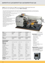
<strong>quantum</strong><br />
MASCHINEN - GERMANY<br />
Operating manual<br />
Version 1.2.5<br />
Bench drill<br />
B 13<br />
B 14<br />
B 16<br />
B 20 / B20 Vario<br />
Pillar drill<br />
B 25 / B 25 Vario<br />
B 32 / B 32 Vario<br />
Illustr. 0-1: B13 B 25<br />
© 2007<br />
Keep for future reference !<br />
GB<br />
18 / 01 / 2008 Version 1.2.5 B 13 / B14 / B16 / B20 / B25 / B32 Drilling machine<br />
Page 1
<strong>quantum</strong><br />
MASCHINEN - GERMANY<br />
Table of contents<br />
1 Safety<br />
1.1 Safety warnings (warning notes) .................................................................................. 5<br />
1.1.1 Classification of hazards ............................................................................... 5<br />
1.1.2 Further ideograms ......................................................................................... 6<br />
1.2 Proper use .................................................................................................................... 6<br />
1.3 Possible dangers caused by the drilling machine ......................................................... 7<br />
1.4 Qualification of employees ........................................................................................... 8<br />
1.4.1 Target group .................................................................................................. 8<br />
1.4.2 Authorized persons ....................................................................................... 8<br />
1.5 User’s position .............................................................................................................. 9<br />
1.6 Safety devices ..............................................................................................................9<br />
1.6.1 ON / OFF switch .......................................................................................... 10<br />
1.6.2 Drilling machine table .................................................................................. 10<br />
1.7 Separating protective devices .................................................................................... 10<br />
1.7.1 Drill chuck protection ................................................................................... 10<br />
1.7.2 Protective cover of the pulleys .................................................................... 11<br />
1.7.3 Prohibition, warning and mandatory labels ................................................. 11<br />
1.8 Safety check ............................................................................................................... 11<br />
1.9 Personal protective equipment ................................................................................... 11<br />
1.10 Safety during operation .............................................................................................. 12<br />
1.11 Safety during maintenance ......................................................................................... 12<br />
1.12 Use of lifting equipment .............................................................................................. 13<br />
1.12.1 Mechanical maintenance work .................................................................... 13<br />
1.13 Accident report ........................................................................................................... 13<br />
1.14 Electric ........................................................................................................................ 13<br />
2 Technical Data<br />
2.1 Power connection ....................................................................................................... 14<br />
2.2 Drilling capacity .......................................................................................................... 14<br />
2.3 Spindle holding fixture ................................................................................................ 14<br />
2.4 Drilling machine table ................................................................................................. 14<br />
2.10 Emissions ................................................................................................................... 15<br />
2.5 Dimensions ................................................................................................................. 15<br />
2.6 Working area .............................................................................................................. 15<br />
2.7 Revolutions .................................................................................................................15<br />
2.8 Environmental conditions ........................................................................................... 15<br />
2.9 Operating material ...................................................................................................... 15<br />
3 Assembly<br />
3.1 Extent of supply .......................................................................................................... 16<br />
3.2 Transport .................................................................................................................... 16<br />
3.3 Storage ....................................................................................................................... 17<br />
3.4 Installation and assemby ............................................................................................ 17<br />
3.4.1 Assembly ..................................................................................................... 17<br />
3.4.2 Installation ................................................................................................... 20<br />
3.4.3 Installation drawings .................................................................................... 20<br />
3.5 First use ...................................................................................................................... 21<br />
3.5.1 Phase inverter for 400V - machines ............................................................ 22<br />
Page 2 Drilling machine B 13 / B14 / B16 / B20 / B25 / B32 Version 1.2.5 18 / 01 / 2008<br />
© 2007 GB
<strong>quantum</strong><br />
MASCHINEN - GERMANY<br />
4 Handling<br />
4.1 Safety ......................................................................................................................... 23<br />
4.2 Control and indicating elements ................................................................................. 23<br />
4.2.1 B 13, B 14 ................................................................................................... 23<br />
4.2.2 B 16, B 20, B 25, B 32, B20 Vario, B25 Vario, B32 Vario ........................... 24<br />
4.2.3 Drill depth stop ............................................................................................ 24<br />
4.2.4 Inclination of the drilling machine table ....................................................... 25<br />
4.3 Speed alternation ....................................................................................................... 26<br />
4.3.1 Speed table ................................................................................................. 27<br />
4.4 Standard values for speeds with HSS – Eco – twist drill ............................................ 31<br />
4.5 Drill chuck ................................................................................................................... 32<br />
4.5.1 Gear rim-drill chuck ..................................................................................... 32<br />
4.5.2 Disassembly of the drill chuck ..................................................................... 32<br />
4.6 Cooling ....................................................................................................................... 32<br />
4.7 Before starting the working process ........................................................................... 32<br />
4.8 During the working process ........................................................................................ 33<br />
5 Maintenance<br />
5.1 Safety ......................................................................................................................... 35<br />
5.1.1 Preparation ................................................................................................. 35<br />
5.1.2 Restarting .................................................................................................... 35<br />
5.2 Inspection and maintenance ...................................................................................... 35<br />
5.3 Repair ......................................................................................................................... 37<br />
6 Ersatzteile - Spare parts B13, B14, B16, B20, B25, B32<br />
6.1 Ersatzteilzeichnung - Parts drawing B13 / B14 .......................................................... 38<br />
6.2 Bohrfutterschutz B13, B14 - Drill chuck protection B13, B14 ..................................... 39<br />
6.2.1 Ersatzteilliste - Parts list B13 / B14 ............................................................. 39<br />
6.3 Ersatzteilzeichnung - Parts drawing B 16 ................................................................... 41<br />
6.4 Bohrfutterschutz B16 - Drill chuck protection B16 ...................................................... 42<br />
6.4.1 Ersatzteilliste - Parts list B16 ....................................................................... 42<br />
6.5 Ersatzteilzeichnung - Parts drawing B20 / B25 (Vario) .............................................. 44<br />
6.6 Bohrfutterschutz B20, B25 - Drill chuck protection B20, B25 ..................................... 45<br />
6.6.1 Ersatzteilliste - Parts list B20 / B25 (Vario) ................................................. 45<br />
6.7 Ersatzteilzeichnung - Parts drawing B32 (Vario) ........................................................ 48<br />
6.8 Bohrfutterschutz B32 - Drill chuck protection B32 ...................................................... 49<br />
6.8.1 Ersatzteilliste - Parts list B32 (Vario) ........................................................... 49<br />
6.9 Schaltplan - Wiring diagram B13-B20 (230V) ............................................................ 52<br />
6.10 Schaltplan - Wiring diagram B20-B32 (400V) ............................................................ 52<br />
6.11 Schaltplan - Wiring diagram B20Vario-B32Vario (230V) ............................................ 53<br />
7 Malfunctions<br />
8 Appendix<br />
8.1 Copyright .................................................................................................................... 56<br />
8.2 Terminology/Glossary ................................................................................................ 56<br />
8.3 Warranty ..................................................................................................................... 57<br />
8.4 Disposal ...................................................................................................................... 57<br />
8.5 RoHS , 2002/95/CE .................................................................................................... 57<br />
8.6 Product follow-up ........................................................................................................ 58<br />
8.7 EC - declaration of conformity .................................................................................... 59<br />
GB<br />
© 2007<br />
18 / 01 / 2008 Version 1.2.5 B 13 / B14 / B16 / B20 / B25 / B32 Drilling machine<br />
Page 3
<strong>quantum</strong><br />
MASCHINEN - GERMANY<br />
Safety<br />
1 Safety<br />
Glossary of symbols<br />
<br />
<br />
gives further advice<br />
calls on you to get in action<br />
• enumeration<br />
<br />
notice<br />
This part of the operating manual<br />
• does explain the meaning and how to use the warning references contained in this operating<br />
manual,<br />
• does explain how to use the drilling machine,<br />
• highlights the dangers that might arise for you and others if these instructions are not followed<br />
thoroughly,<br />
• informs you on how to prevent dangers.<br />
In addition to this operating manual, please note<br />
• applicable laws and regulations,<br />
• legal regulations for preventing an accident,<br />
• the prohibition, warning and mandatory signs as well as the warning notes on the drilling<br />
machine.<br />
European standards must be kept during installation, operation, maintenance and repair of the<br />
drilling machine.<br />
If European standards are not applied at the national legislation of the country of destination, the<br />
specific applicable regulations of each country are to be observed.<br />
If necessary, the required measures must be taken to comply with the specific regulations of<br />
each country before the drilling machine is used for the first time.<br />
Always keep the operating manual close to the drilling machine for further reference.<br />
INFORMATION<br />
If you are not able to solve a problem using this manual, please do not hesitate to contact us for<br />
further professional advice:<br />
Optimum Maschinen Germany GmbH<br />
Dr. Robert-Pfleger-Str. 26<br />
D- 96103 Hallstadt<br />
info@optimum-maschinen.de<br />
Page 4 Drilling machine B 13 / B14 / B16 / B20 / B25 / B32 Version 1.2.5 18 / 01 / 2008<br />
© 2007 GB
Safety<br />
<strong>quantum</strong><br />
MASCHINEN - GERMANY<br />
1.1 Safety warnings (warning notes)<br />
1.1.1 Classification of hazards<br />
We classify the safety warnings into various levels. The table below gives an overview of the<br />
classification of symbols (ideogram) and warning signs for each specific danger and its (possible)<br />
consequences.<br />
ideogram warning alert definition / consequence<br />
DANGER!<br />
WARNING!<br />
CAUTION!<br />
ATTENTION!<br />
Threatening danger that will cause serious injury or<br />
death to people.<br />
Risk: A danger that might cause serious injury or death<br />
to a person.<br />
Danger or unsafe procedure that might cause injury to<br />
people or damage to property.<br />
Situation that could cause damage to the machine and<br />
to the product and other types of damages.<br />
No risk of injury to people.<br />
INFORMATION<br />
Application advice and other important or useful information<br />
and notes.<br />
No dangerous or harmful consequences for people or<br />
objects.<br />
In case of certain dangers, we replace the ideogram by<br />
or<br />
general danger<br />
with a warning<br />
of<br />
injuries to<br />
hands,<br />
hazardous<br />
electrical voltage,<br />
rotating parts.<br />
GB<br />
© 2007<br />
18 / 01 / 2008 Version 1.2.5 B 13 / B14 / B16 / B20 / B25 / B32 Drilling machine<br />
Page 5
<strong>quantum</strong><br />
MASCHINEN - GERMANY<br />
Safety<br />
1.1.2 Further ideograms<br />
Warning of automatic<br />
start-up!<br />
Activation forbidden!<br />
Pull the main plug!<br />
Use safety<br />
glasses!<br />
Use ear protection!<br />
Use protective<br />
gloves!<br />
Use protective<br />
boots!<br />
Wear a safety suit!<br />
Protect the environment!<br />
Contact address<br />
1.2 Proper use<br />
WARNING!<br />
In the event of improper use, the drilling-milling machine<br />
• will endanger personnel,<br />
• will endanger the machine and other material property of the operator,<br />
may affect proper operation of the drilling machine.<br />
The drilling machine is constructed and designed for the use in non-explosive surrounding. The<br />
drilling machine is designed and manufactured to be used for drilling cold metals or other nonflammable<br />
materials or materials that do not constitute a health hazard by using a rotating cutting<br />
tool with various chucking grooves.<br />
If the drilling machine is used in any way other than as described above, modified without the<br />
authorisation of Optimum Maschinen GmbH or operated with different process data, then it is<br />
being used improperly.<br />
We do not take liability for damage caused by improper use.<br />
We would like to stress that any modifications to the construction, or technical or technological<br />
modifications that have not been authorised by Optimum Maschinen GmbH will also render the<br />
guarantee null and void.<br />
It is also part of proper use that<br />
• the maximum values for the drilling machine are complied with,<br />
• the operating manual is observed,<br />
• inspection and maintenance instructions are observed.<br />
„Technical Data“ on page 14<br />
Page 6 Drilling machine B 13 / B14 / B16 / B20 / B25 / B32 Version 1.2.5 18 / 01 / 2008<br />
© 2007 GB
Safety<br />
<strong>quantum</strong><br />
MASCHINEN - GERMANY<br />
WARNING!<br />
Very serious injury.<br />
It is forbidden to make any modifications or alternations to the operating values of the<br />
drilling machine! They could endanger employees and cause damage to the drilling<br />
machine.<br />
1.3 Possible dangers caused by the drilling machine<br />
The drilling machine is state of the art.<br />
Nevertheless, there is a residual risk as the drilling machine operates with<br />
• high revolutions,<br />
• rotating parts,<br />
• electrical voltage and currents.<br />
We have used construction resources and safety techniques to minimize the health risk to persons<br />
resulting from these hazards.<br />
If the drilling machine is used and maintained by employees who are poorly qualified, then there<br />
might be a risk resulting from incorrect operation and unsuitable maintenance of the drilling<br />
machine.<br />
INFORMATION<br />
Everyone involved in the assembly, commissioning, operation and maintenance must<br />
• be duly qualified,<br />
• strictly follow this operating manual.<br />
Due to improper use<br />
• there is a risk for the employee,<br />
• the machine and further property might be endangered,<br />
• the function of the drilling machine could be affected.<br />
Always disconnect the drilling machine if cleaning or maintenance work is being carried out.<br />
WARNING!<br />
The drilling machine may only be used with the safety devices activated.<br />
Disconnect the drilling machine immediately whenever you detect a failure in the safety<br />
devices or when they are not mounted!<br />
All additional installations carried out by the operator must incorporate the safety<br />
devices prescribed.<br />
This is your responsibility being the operator!<br />
„Safety devices“ on page 9<br />
GB<br />
© 2007<br />
18 / 01 / 2008 Version 1.2.5 B 13 / B14 / B16 / B20 / B25 / B32 Drilling machine<br />
Page 7
<strong>quantum</strong><br />
MASCHINEN - GERMANY<br />
Safety<br />
1.4 Qualification of employees<br />
1.4.1 Target group<br />
This manual applies to<br />
• the operators,<br />
• the users,<br />
• the maintenance staff.<br />
Therefore, the warning notes refer to both operation and maintenance of the drilling machine.<br />
Determine clearly and make a permanent decision in who will be responsible for the different<br />
activities on the machine (operation, maintenance and repair).<br />
Vague and unclear assignment of responsibilities constitute a safety hazard!<br />
Always disconnect the main plug of the drilling machine. This will prevent it from being used by<br />
unauthorized persons.<br />
1.4.2 Authorized persons<br />
WARNING!<br />
Incorrect use and maintenance of the drilling machine constitute a danger for the staff,<br />
objects and the environment.<br />
Only authorized persons may operate the drilling machine!<br />
Persons authorized to operate and maintain should be trained technical staff and<br />
instructed by the ones who are working for the operator and for the manufacturer.<br />
The operator must<br />
Obligations<br />
of the operator<br />
• train the staff,<br />
• instruct the staff in regular intervals (at least once a year) on<br />
- all safety standards that apply to the drilling machine,<br />
- the operation,<br />
- accredited technical guidelines,<br />
• check the knowledge of the staff,<br />
• document training / instructions,<br />
• require the staff to confirm participation in training / instructions by means of a signature,<br />
• check if the staff is aware of safety rules and dangers in the workplace so that they observe<br />
the operating manual.<br />
The user must<br />
Obligations<br />
of the user<br />
Further<br />
requirements<br />
to the<br />
qualification<br />
• have followed a training on the operation of the drilling machine,<br />
• know the function and performance,<br />
• before commissioning<br />
- have read and understood the operating manual,<br />
- be familiar with all safety devices and regulations.<br />
For working on the following machine parts, additional requirements are being applied:<br />
• Electrical parts or operating agents: shall only be performed by an electrician or under the<br />
guidance and supervision of an electrician.<br />
Before starting work on electrical parts or operating agents, following measures are to be performed<br />
in the following order.<br />
Page 8 Drilling machine B 13 / B14 / B16 / B20 / B25 / B32 Version 1.2.5 18 / 01 / 2008<br />
© 2007 GB
Safety<br />
<strong>quantum</strong><br />
MASCHINEN - GERMANY<br />
disconnect all poles<br />
secure against switching on<br />
check dead circuit<br />
1.5 User’s position<br />
The user must stand in front of the drilling machine.<br />
INFORMATION<br />
The main switch of the drilling machine must be easily accessible.<br />
1.6 Safety devices<br />
Operate the drilling machine only with properly functioning safety devices.<br />
Stop the drilling machine immediately if there is a failure in the safety device or if it is not functioning<br />
for some reason.<br />
It is your responsibility!<br />
If the safety device has been activated or has failed, the drilling machine must only be operated<br />
again when<br />
• the cause of the failure has been removed,<br />
• you have made sure that there is no existing danger for persons or objects.<br />
WARNING!<br />
If you bypass, remove or override a safety device in any other way, you are endangering<br />
yourself and other persons working on the drilling machine. The possible consequences<br />
are the following<br />
• injuries due to components or parts of components flying off at high speed,<br />
• contact with rotating parts,<br />
• fatal electrocution.<br />
The drilling machine includes the following safety devices:<br />
• an EMERGENCY-STOP button,<br />
• a drilling machine table with grooves to fasten the workpiece or a vice,<br />
• a fixed screwed-on protective cover for the pulleys with micro switch,<br />
• a drill chuck guard with micro switch.<br />
GB<br />
© 2007<br />
18 / 01 / 2008 Version 1.2.5 B 13 / B14 / B16 / B20 / B25 / B32 Drilling machine<br />
Page 9
<strong>quantum</strong><br />
MASCHINEN - GERMANY<br />
Safety<br />
1.6.1 ON / OFF switch<br />
The lockable switch is equipped with an<br />
EMERGENCY-STOP function and a<br />
release for undervoltage.<br />
ON / OFF switch<br />
Illustr.1-1: On / OFF switch<br />
Open the cap of the switch in order to switch the drilling machine on.<br />
CAUTION!<br />
Even if the EMERGENCY-STOP button is activated the spindle will keep turning for several<br />
seconds - depending on the pre-selected number of revolutions.<br />
1.6.2 Drilling machine table<br />
On the drilling machine table there are<br />
holding fittings for sliding blocks.<br />
WARNING!<br />
There is danger of injury because of the<br />
parts flying off. Tighten the workpiece<br />
properly into the drilling machine table.<br />
holding fixtures for<br />
grooves<br />
(14 mm)<br />
Illustr.1-2: drilling machine table<br />
1.7 Separating protective devices<br />
1.7.1 Drill chuck protection<br />
Adjust the protective equipment to the correct<br />
height before you start working.<br />
To do so, detach the clamping screw,<br />
adjust the required height and retighten the<br />
clamping screw.<br />
A switch is integrated in the fixture of the<br />
spindle protection which monitors that the<br />
cover is closed.<br />
INFORMATION<br />
YOU CANNOT START THE MACHINE IF<br />
THE DRILL CHUCK PROTECTION IS<br />
NOT CLOSED.<br />
Drill chuck protection<br />
Illustr.1-3: Drill chuck protection<br />
Page 10 Drilling machine B 13 / B14 / B16 / B20 / B25 / B32 Version 1.2.5 18 / 01 / 2008<br />
© 2007 GB
Safety<br />
<strong>quantum</strong><br />
MASCHINEN - GERMANY<br />
1.7.2 Protective cover of the pulleys<br />
A protective cover for the belt pulleys is<br />
mounted on the drilling head. A switch is<br />
integrated in the protective cover which<br />
monitors that the cover is closed.<br />
INFORMATION<br />
YOU CANNOT START THE MACHINE IF<br />
THE PROTECTIVE COVER IS NOT<br />
CLOSED.<br />
protective cover<br />
Illustr.1-4: protective cover<br />
1.7.3 Prohibition, warning and mandatory labels<br />
INFORMATION<br />
All warning labels must be legible. Check them regularly.<br />
1.8 Safety check<br />
Check the drilling machine at least once per shift. Inform the person responsible immediately of<br />
any defect or change in the operating function.<br />
Check all safety devices<br />
• at the beginning of each shift (with the machine stopped),<br />
• once a week (with the machine in operation),<br />
• after every maintenance and repair work.<br />
Check that the prohibition, warning and information labels as well as the markings on the drilling<br />
machine<br />
• are legible (clean them, if necessary),<br />
• are complete.<br />
1.9 Personal protective equipment<br />
For certain work, personal protective equipment is required, such as:<br />
• safety helmet,<br />
• protective glasses or face guard,<br />
• protective gloves,<br />
• safety shoes with steel caps,<br />
• ear protection.<br />
Before starting work, make sure that the prescribed personal protective equipment is available<br />
at the workplace.<br />
CAUTION!<br />
© 2007<br />
Dirty or eventually contaminated personal protective equipment might cause disease.<br />
Clean your personal protective equipment<br />
• after each use,<br />
• regularly once a week.<br />
GB<br />
18 / 01 / 2008 Version 1.2.5 B 13 / B14 / B16 / B20 / B25 / B32 Drilling machine<br />
Page 11
<strong>quantum</strong><br />
MASCHINEN - GERMANY<br />
Safety<br />
Personal protective equipment for special work<br />
Protect your face and your eyes: Wear a safety helmet with a face guard for every work, especially<br />
for the kind of work where your face and eyes are exposed to hazards.<br />
Use protective gloves when lifting or handling pieces with sharp edges.<br />
Wear safety shoes when fitting, dismanteling or transporting heavy components.<br />
1.10 Safety during operation<br />
In the description of work with and on the drilling machine we highlight the dangers specific to<br />
that work.<br />
WARNING!<br />
Before activating the drilling machine, double check that this will<br />
• not endanger other people,<br />
• not cause damage to equipment.<br />
Avoid unsafe working practice:<br />
• Make sure that your work does not endanger anyone.<br />
• The instructions of this manual must be observed strictly during assemby, operation, maintenance<br />
and repair.<br />
• Do not work on the drilling machine, if your concentration is reduced, for example, because<br />
you are taking medication.<br />
• Observe the regulations for the prevention of accidents issued by your association for the<br />
prevention of accidents and safety in the workplace or other inspection authorities.<br />
• Inform the inspector of any danger or failure.<br />
• Stay at the drilling machine until all rotating parts have come to a halt.<br />
• Use the prescribed personal protective equipment. Make sure to wear a well-fitting work suit<br />
and a hainet, if necessary.<br />
• Do not use protective gloves when drilling.<br />
1.11 Safety during maintenance<br />
Inform the operating staff on time of any repair and maintenance work.<br />
Report all safety-relevant changes or performance details of the drilling machine.Document all<br />
changes, have the operating manual changed accordingly and train the machine operators.<br />
Switching-off and securing the drilling machine<br />
Unplug the main switch before starting any maintenance or repair work.<br />
All machine components and hazardous voltages are disconnected.Only the positions which are<br />
marked with the pictogram in the margin are excluded. Attach a warning sign on the machine.<br />
Page 12 Drilling machine B 13 / B14 / B16 / B20 / B25 / B32 Version 1.2.5 18 / 01 / 2008<br />
© 2007 GB
Safety<br />
<strong>quantum</strong><br />
MASCHINEN - GERMANY<br />
1.12 Use of lifting equipment<br />
WARNING!<br />
Use of unstable lifting and load-suspension gear that might break under load can cause<br />
very serious injuries or even death.<br />
Check the lifting and load-suspension gear on<br />
• sufficient load capacity,<br />
• perfect condition.<br />
Observe the regulations for the prevention of accidents issued by your association for<br />
the prevention of occupational accidents and safety in the workplace or other inspection<br />
authorities.<br />
Fasten the loads properly. Do not walk under lifted loads !<br />
1.12.1 Mechanical maintenance work<br />
Remove all protection and safety devices before starting maintenance work and re-install them<br />
once the work has been completed, such as:<br />
• covers,<br />
• safety indications and warning signs,<br />
• earth (ground) cables.<br />
If you remove protection or safety devices, refit them immediately after completing the work.<br />
Check if they are working properly!<br />
1.13 Accident report<br />
1.14 Electric<br />
Inform your superiors and Optimum Maschinen GmbH immediately in case of accidents, possible<br />
sources of danger and any action which almost lead to an accident "near misses".<br />
"Near misses" may have many possible causes.<br />
The sooner they are notified, the faster theses causes can be eliminated.<br />
Have the machine and / or the electrical equipment checked regularly, at least every six months.<br />
Eliminate immediately all defects such as loose connections, defective wires, etc.<br />
A second person must be present during work on live components, to disconnect the power in<br />
case of an emergency.<br />
Disconnect the drilling machine immediately if there is a malfunction in the power supply!<br />
„Maintenance“ on page 34<br />
GB<br />
© 2007<br />
18 / 01 / 2008 Version 1.2.5 B 13 / B14 / B16 / B20 / B25 / B32 Drilling machine<br />
Page 13
<strong>quantum</strong><br />
MASCHINEN - GERMANY<br />
Technical Data<br />
2 Technical Data<br />
The following data which give dimensions and weight are the manufacturer’s authorized<br />
machine data.<br />
2.1 Power connection<br />
power connection~50Hz<br />
230 V<br />
300 W<br />
2.2 Drilling capacity<br />
B 13 B 14 B 16 B 20<br />
B 20 Vario<br />
230 V<br />
350W<br />
230 V<br />
450 W<br />
3 x 400 V<br />
550 W<br />
or<br />
230 V<br />
550 W<br />
B 25<br />
B 25 Vario<br />
3 x 400 V<br />
550 W<br />
230V<br />
550 W<br />
B 32<br />
B 32 Vario<br />
3 x 400 V<br />
1,1 kW<br />
230V<br />
1,1 kW<br />
B 13 B 14 B 16 B 20 B 25 B 32<br />
drilling capacity in steel<br />
[mm]<br />
13 14 16 20 20 32<br />
reach [mm] 104 104 125 170 170 225<br />
spindle sleve travel [mm] 50 50 65 80 80 125<br />
2.3 Spindle holding fixture<br />
B 13 B 14 B 16 B 20 B 25 B 32<br />
spindle holding fixture firm/B16 firm/B16 MK2 MK2 MK3 MK4<br />
2.4 Drilling machine table<br />
B 13 B 14 B 16 B 20 B 25 B 32<br />
slewable on the spindle<br />
axis [mm]<br />
length x width of the working<br />
area<br />
160 x 160 160 x 160 200 x 200 275 x 275 275 x 275 360 x 360<br />
T-groove dimension [mm] 14 14 14 14 14 14<br />
maximum distance [mm]<br />
spindle table<br />
working area stand [mm]<br />
length x width of the working<br />
area<br />
240 340 390 450 760 660<br />
135 x 175 140 x 180 160 x 170 205 x 200 235 x 220 260 x 270<br />
Page 14 Drilling machine B 13 / B14 / B16 / B20 / B25 / B32 Version 1.2.5 18 / 01 / 2008<br />
© 2007 GB
Technical Data<br />
<strong>quantum</strong><br />
MASCHINEN - GERMANY<br />
2.5 Dimensions<br />
B 13 B 14 B 16 B 20 B 25 B 32<br />
height [mm] 580 700 820 990 1570 1730<br />
depth [mm] 420 420 510 700 690 790<br />
width [mm] 220 230 270 300 390 400<br />
total weight [kg] 21 24 38 56 63 138<br />
column diameter [mm] 46 46 60 70 70 92<br />
2.6 Working area<br />
B 13 B 14 B 16 B 20 B 25 B 32<br />
height [mm] 2050 2050 2050 2050 2050 2050<br />
depth [mm] 2000 2000 2000 2000 2000 2000<br />
width [mm] 1400 1400 1400 1400 1400 1400<br />
2.7 Revolutions<br />
B 13<br />
B 14<br />
spindle revolutions • 619<br />
• 837<br />
• 1314<br />
• 1807<br />
• 2435<br />
B 16 B 20<br />
B 25<br />
• 459<br />
• 579<br />
• 787<br />
• 1255<br />
• 2100<br />
2.8 Environmental conditions<br />
• 268<br />
• 323<br />
• 376<br />
• 453<br />
• 516<br />
• 533<br />
• 796<br />
• 1029<br />
• 1257<br />
• 1274<br />
• 1783<br />
• 2209<br />
B 20 Vario<br />
B 25 Vario<br />
• 16 - 686<br />
• 19 - 827<br />
• 22 - 963<br />
• 27 - 1161<br />
• 31 - 1323<br />
• 32 - 1367<br />
• 47 - 2041<br />
• 61 - 2636<br />
• 74 - 3221<br />
• 75 - 3265<br />
• 105 - 3500<br />
• 131 - 3500<br />
B 32<br />
• 167<br />
• 288<br />
• 339<br />
• 379<br />
• 489<br />
• 585<br />
• 1106<br />
• 1368<br />
• 1970<br />
B 32 Vario<br />
• 10 - 429<br />
• 17 - 739<br />
• 20 - 870<br />
• 22 - 970<br />
• 29 - 1253<br />
• 35 - 1498<br />
• 65 - 2835<br />
• 81 - 3500<br />
• 117 - 3500<br />
B 13 B 14 B 16 B 20 B 25 B 32<br />
temperature 5 - 35 °C<br />
humidity 25 - 80 %<br />
2.9 Operating material<br />
toothed rack<br />
drilling column<br />
commercial slide bearing grease<br />
acid-free lubricating oil<br />
2.10 Emissions<br />
The emission of the drilling machine is below 76 dB(A). If the drilling machine is installed in an<br />
area where various machines are in operation, the acoustic influence (immission) on the operator<br />
of the drilling machine may exceed 85 dB(A).<br />
© 2007<br />
We recommend the use of soundproofing and ear protection.<br />
Please note that the duration of the acoustic noise expose, the kind and nature of the working<br />
area as well as other machines may influence the noise level in the workplace.<br />
GB<br />
18 / 01 / 2008 Version 1.2.5 B 13 / B14 / B16 / B20 / B25 / B32 Drilling machine<br />
Page 15
<strong>quantum</strong><br />
MASCHINEN - GERMANY<br />
Assembly<br />
3 Assembly<br />
3.1 Extent of supply<br />
When the drilling machine is delivered, check immediately that the machine has not been damaged<br />
during shipping and that all components are included. Also check that no fastening screws<br />
have come loose.<br />
The delivery volume contains:<br />
B13 / B14 B16 B20<br />
B20 Vario<br />
B25 / B32<br />
B25 Vario<br />
B32 Vario<br />
• drilling head • drilling head • drilling head • drilling head<br />
• drilling table with premounted<br />
clamping lever<br />
• drilling table with premounted<br />
clamping lever<br />
• drilling table<br />
• drilling table support<br />
• handle<br />
• drilling table<br />
• drilling table support<br />
• handle<br />
• stand • stand • stand • stand<br />
• column component with<br />
premounted table support<br />
• column component with<br />
premounted table support<br />
• column component<br />
• toothed rod<br />
• guide ring<br />
• column component<br />
• toothed rod<br />
• guide ring<br />
• gear rim drill chuck (B13)<br />
• quick action drill chuck<br />
(B14)<br />
• quick action drill chuck<br />
• morse cone MK2<br />
• drill drift<br />
• quick action drill chuck<br />
• morse cone MK2<br />
• drill drift<br />
• quick action drill chuck<br />
• morse cone MK3<br />
(B25 / Vario)<br />
• morse cone MK4<br />
(B32 / Vario)<br />
• drill drift<br />
• 3 x handle bar star handle<br />
• 3 x handle bar star handle<br />
• 3 x handle rod star handle<br />
• 3 x handle rod star handle<br />
• assembly set • assembly set • assembly set • assembly set<br />
• operating manual • operating manual • operating manual • operating manual<br />
• for 400 V: CEE - 16 A,<br />
phase inverter<br />
• CEE - 16 A,<br />
phase inverter<br />
3.2 Transport<br />
WARNING!<br />
Machine parts falling off forklift trucks or transport vehicles could cause very serious or<br />
even fatal injuries. Follow the instructions and information on the transport case:<br />
• centres of gravity<br />
• suspension points<br />
• weights<br />
• means of transport to be used<br />
• prescribed shipping position<br />
WARNING!<br />
Use of unstable lifting equipment and load-suspension devices that break under load can<br />
cause very serious injuries or even death.<br />
Check that lifting and load suspension gear has sufficient load capacity and that it is in<br />
perfect condition.<br />
Page 16 Drilling machine B 13 / B14 / B16 / B20 / B25 / B32 Version 1.2.5 18 / 01 / 2008<br />
© 2007 GB
Assembly<br />
<strong>quantum</strong><br />
MASCHINEN - GERMANY<br />
3.3 Storage<br />
Observe the rules for preventing accidents issued by your association for the prevention<br />
of accidents or other inspection authorities. Hold the loads properly. Never walk under<br />
suspended loads!<br />
ATTENTION!<br />
Improper storage may cause important parts to be damaged or destroyed. Store packed<br />
or unpacked parts only under the following ambient conditions:<br />
„Environmental conditions“ on page 15<br />
Consult Optimum Maschinen GmbH if the drilling machine and accessories have to be stored<br />
for a period of over three monthes or under different external conditions than those given here.<br />
3.4 Installation and assemby<br />
3.4.1 Assembly<br />
WARNING!<br />
Danger of crushing when grouping, assembling and mounting the machine components.<br />
Assembly of stand and tripod<br />
INFORMATION<br />
You need a hexagon spanner 17mm and the hexagon bolts contained in the delivery volume to<br />
assemble the drilling machine.<br />
Put the stand on the floor and fix the drill<br />
column to the stand. Hexagon bolts are<br />
provided to fix it.<br />
drill column<br />
hexagon bolts<br />
stand<br />
Illustr.3-1: Assembly drill column<br />
© 2007<br />
GB<br />
18 / 01 / 2008 Version 1.2.5 B 13 / B14 / B16 / B20 / B25 / B32 Drilling machine<br />
Page 17
<strong>quantum</strong><br />
MASCHINEN - GERMANY<br />
Assembly<br />
Assembly of the drilling machine table B16, B20, B25 and B32 / Vario<br />
Introduce the toothed rack into the support<br />
for the drilling machine table.<br />
Adjust the toothed rack within the drilling<br />
machine table in a way that the<br />
teeth of the toothed rack cam into the<br />
spiral wheel of the support for the drilling<br />
machine table.<br />
Push the complete table with the<br />
toothed rack onto the tripod.<br />
support for drilling<br />
machine table<br />
toothed rack<br />
tripod<br />
Illustr.3-2: Assembly of the drilling<br />
machine table (B20)<br />
INFORMATION<br />
The larger part without toothing of the toothed rack must be upside.<br />
Push the guide ring on the column and<br />
on the toothed rack.<br />
Fix the guide ring with the stud bolt.<br />
Make sure that the drilling table is still turning<br />
easily around the drill column.<br />
guide ring<br />
stud bolt<br />
Mount the crank handle for height<br />
adjustment of the drill head.<br />
Clamp the crank handle with the stud<br />
bolt.<br />
crank handle<br />
Illustr.3-3: Assembly guide ring<br />
Illustr.3-4: Assembly crank handle<br />
Page 18 Drilling machine B 13 / B14 / B16 / B20 / B25 / B32 Version 1.2.5 18 / 01 / 2008<br />
© 2007 GB
Assembly<br />
<strong>quantum</strong><br />
MASCHINEN - GERMANY<br />
Put the drilling table onto the drilling<br />
support. Mount the clamping lever.<br />
clamping lever<br />
Mount the drilling table B13 , B14<br />
Push the drilling table support with<br />
mounted drilling table onto the column.<br />
drilling table support<br />
Illustr.3-5: Assembly drilling table<br />
Illustr.3-6: Assembly drilling table B13/<br />
B14<br />
Assembly of the drilling head<br />
Put the drilling head on the tripod and<br />
turn it until it aligns with the stand.<br />
Make sure that the drilling head is<br />
completely fixed onto the tripod.<br />
Tighten the drilling head with the two set<br />
screws.<br />
Mount the three levers of the feed cross.<br />
Lever<br />
stud bolt<br />
Illustr.3-7: Assembly drilling head<br />
GB<br />
© 2007<br />
18 / 01 / 2008 Version 1.2.5 B 13 / B14 / B16 / B20 / B25 / B32 Drilling machine<br />
Page 19
<strong>quantum</strong><br />
MASCHINEN - GERMANY<br />
Assembly<br />
3.4.2 Installation<br />
Check the horizontal orientation of the base of the drilling machine with a spirit level.<br />
Attach the drilling machine to the base using the holes in the stand.<br />
The place where the drilling machine is installed must comply with ergonomic workplace requirements.<br />
ATTENTION!<br />
Tighten the setscrews on the drilling machine only until it is firmly secured and can neither<br />
move during operation nor be turned over.<br />
If the setscrews are too tight and the base is uneven, the stand of the drilling machine may<br />
break.<br />
3.4.3 Installation drawings<br />
B 25 / B32<br />
Illustr. 3-8: B25<br />
B32<br />
Page 20 Drilling machine B 13 / B14 / B16 / B20 / B25 / B32 Version 1.2.5 18 / 01 / 2008<br />
© 2007 GB
Assembly<br />
<strong>quantum</strong><br />
MASCHINEN - GERMANY<br />
3.5 First use<br />
WARNING!<br />
Staff and equipment may be endangered if the drilling machine is first used by unexpert<br />
staff. We do not take responsibility for damage caused by incorrect commissioning.<br />
Power supply<br />
Connect the main plug of the drilling machine to the power supply.<br />
Check the fuse protection of your power supply to the technical data for the power consumption<br />
of the engine.<br />
ATTENTION!<br />
Please pay attention that all three phases (L1, L2, L3) for 400V - drilling machines are<br />
connected correctly.<br />
Most engine failures result from incorrect connection, for instance the neutral connector<br />
(N) is being connected to a phase.<br />
This might lead to the following results:<br />
• The engine does get quickly very hot.<br />
• The engine noise increases, i. e. becomes louder.<br />
• The engine has no power.<br />
When the phases are connected incorrectly, the guarantee is null and void.<br />
ATTENTION!<br />
Drilling machines with frequency converter should not be operated with a CEE plug. Connect<br />
the machine permanently to a connection box (see EN 50178/5.2.11.1)<br />
INFORMATION<br />
The frequency converter (driving regulator) might release the FI protected switch of your electrical<br />
supply. In order to avoid any malfunctioning, you either need an FI protected switch sensitive<br />
for pulse current or and AC / DC sensitive one.<br />
In case of a malfunction or release of the FI protected switch, please check the type installed.<br />
The following signs indicate if you have one of the FI protected switches described above.<br />
FI protected switch sensitive to pulse current<br />
FI protected switch sensitive to AC/DC<br />
Typ A<br />
Typ B<br />
300 mA 300 mA<br />
© 2007<br />
We recommend you to use an FI protected switch sensitive to AC/DC. FI protected switches<br />
sensitive to AC/DC (RCCB, type B are adequate for 1 phase and 3 phase fed frequency converters<br />
(driving regulators).<br />
An FI protected switch type AC (only for alternating current (AC)) is not appropriate for frequency<br />
converters. FI protected switches type AC are no longer used.<br />
„Qualification of employees“ on page 8<br />
GB<br />
18 / 01 / 2008 Version 1.2.5 B 13 / B14 / B16 / B20 / B25 / B32 Drilling machine<br />
Page 21
<strong>quantum</strong><br />
MASCHINEN - GERMANY<br />
Assembly<br />
3.5.1 Phase inverter for 400V - machines<br />
Change the poles by means of the phase<br />
inverter if the turning direction of the drilling<br />
machine is not correct.<br />
Phase inverter<br />
Illustr.3-9: Phase inverter<br />
Page 22 Drilling machine B 13 / B14 / B16 / B20 / B25 / B32 Version 1.2.5 18 / 01 / 2008<br />
© 2007 GB
Handling<br />
<strong>quantum</strong><br />
MASCHINEN - GERMANY<br />
4 Handling<br />
4.1 Safety<br />
Use the drilling machine only under the following conditions:<br />
<br />
<br />
<br />
The drilling machine is in proper working order.<br />
The drilling machine is used as prescribed.<br />
The instruction manual has been followed.<br />
All safety devices are installed and activated.<br />
All malfunctions should be eliminated immediately. Stop the machine immediately at an event of<br />
any malfunction in operation and make sure it cannot be started up accidentally or without<br />
authorization.<br />
Notify the person responsible immediately of any modification.<br />
„Safety during operation“ on page 12<br />
4.2 Control and indicating elements<br />
4.2.1 B 13, B 14<br />
ON / OFF switch with<br />
EMERGENCY STOP<br />
function<br />
pulley drive with housing<br />
handle for V-belt tension<br />
drill depth stop<br />
lever for spindle sleeve feed<br />
drill chuck guard<br />
drilling machine table<br />
table height adjustment<br />
Illustr. 4-1: <strong>quantum</strong> B 13<br />
GB<br />
© 2007<br />
18 / 01 / 2008 Version 1.2.5 B 13 / B14 / B16 / B20 / B25 / B32 Drilling machine<br />
Page 23
<strong>quantum</strong><br />
MASCHINEN - GERMANY<br />
Handling<br />
4.2.2 B 16, B 20, B 25, B 32, B20 Vario, B25 Vario, B32 Vario<br />
potentiometer speed<br />
regulation (only Vario)<br />
pulley drive with housing<br />
ON / OFF switch with<br />
EMERGENCY STOP<br />
function<br />
handle for V-belt tension<br />
lever for spindle sleeve feed<br />
reversing switch<br />
drill chuck guard<br />
drill depth stop<br />
drilling machine table<br />
clamping lever<br />
table height adjustment<br />
adjustment for the inclination of<br />
the drilling machine table<br />
Illustr. 4-2: <strong>quantum</strong> B20 Vario<br />
4.2.3 Drill depth stop<br />
When drilling several holes of the same<br />
depth, you can use the drill depth stop.<br />
• Bei B16 / B20 / B25 / B32:<br />
Unscrew the locking screw and turn the<br />
graduated collar until the required drill<br />
depth superimposes with the pointer.<br />
Retighten the locking screw.<br />
locking screw<br />
drill depth stop<br />
scale<br />
Illustr.4-3: Drill depth stop<br />
B16 - B32<br />
Page 24 Drilling machine B 13 / B14 / B16 / B20 / B25 / B32 Version 1.2.5 18 / 01 / 2008<br />
© 2007 GB
Handling<br />
<strong>quantum</strong><br />
MASCHINEN - GERMANY<br />
• For B 13 / B14:<br />
Adjust the limit screw to the required drilling<br />
depth.<br />
The spindle may only be lowered to the<br />
required drill depth.<br />
limit screw<br />
drill depth stop<br />
scale<br />
Illustr.4-4: Drill depth stop<br />
B13 - B14<br />
4.2.4 Inclination of the drilling machine table<br />
The drilling machine table can be inclined<br />
to the right or to the left.<br />
Loosen the fastening screws.<br />
fastening screw<br />
threaded pin<br />
For B16 / B20 / B25 / B32:<br />
Pull out the threaded pin.<br />
scale<br />
Illustr.4-5: Fastening screw<br />
INFORMATION<br />
If the threaded pin may not be pulled out, the seat may be loosened by turning the nut clockwise.<br />
Adjust the required angle by means of the scale.<br />
Retighten the fastening screw firmly.<br />
INFORMATION<br />
The threaded pin is only provided for correct positioning of a horizontal level of the drilling table.<br />
GB<br />
© 2007<br />
18 / 01 / 2008 Version 1.2.5 B 13 / B14 / B16 / B20 / B25 / B32 Drilling machine<br />
Page 25
<strong>quantum</strong><br />
MASCHINEN - GERMANY<br />
Handling<br />
4.3 Speed alternation<br />
WARNING!<br />
Only open the cover hood when the drilling machine is disconnected from the electrical<br />
power supply.<br />
Close and screw the covering hood after each modification of the number of revolutions.<br />
Disconnect the machine from the electrical<br />
power supply.<br />
V-belt pulleys<br />
Detach the screws on the protective<br />
cover.<br />
Open the protective cover of the belt<br />
drive.<br />
clamping screw<br />
V-belt tension<br />
Illustr.4-6: Clamping screw V-belt<br />
tension<br />
Untighten the clamping screw of the V-belt tension and push the motor in direction of the drill<br />
chuck.<br />
Type Vario:<br />
Adjust the required speed with the potentiometer. Depending on the position of the V-belts on<br />
the V-belt pulleys you will get a certain speed range.<br />
„Speed table“ on page 27<br />
INFORMATION<br />
The drilling machine B 20 , B 25 and B 32 are equipped with a handle by which you may push<br />
the motor in direction of the drill chuck.<br />
Thus the pre-tension of the V-belts is loosened.<br />
Put the V-belt/-s onto the required V-belt pulley/-s.<br />
Retighten the V-belt/-s<br />
Close and rescrew the cover.<br />
ATTENTION!<br />
Make sure that the tension of the V-belts is correct.<br />
If the tension of the V-belts is too high or too low, it may lead to damages. The V-belts are<br />
well tightened if the they could be squeezed approximately 1 cm.<br />
Page 26 Drilling machine B 13 / B14 / B16 / B20 / B25 / B32 Version 1.2.5 18 / 01 / 2008<br />
© 2007 GB
Handling<br />
<strong>quantum</strong><br />
MASCHINEN - GERMANY<br />
4.3.1 Speed table<br />
Speed table B13 / B14<br />
spindle<br />
2435<br />
1807<br />
1314<br />
837<br />
619<br />
engine<br />
Illustr. 4-7: Speed table <strong>quantum</strong> B13 / B14<br />
Speed table B16<br />
spindle<br />
2100<br />
1255<br />
787<br />
579<br />
459<br />
engine<br />
Illustr. 4-8: Speed table <strong>quantum</strong> B16<br />
GB<br />
© 2007<br />
18 / 01 / 2008 Version 1.2.5 B 13 / B14 / B16 / B20 / B25 / B32 Drilling machine<br />
Page 27
<strong>quantum</strong><br />
MASCHINEN - GERMANY<br />
Handling<br />
Speed table B20 / B25<br />
spindle<br />
center pulleys<br />
engine<br />
533<br />
376<br />
268<br />
796<br />
453<br />
323<br />
1274<br />
1029<br />
516<br />
2209<br />
1783<br />
1257<br />
Illustr. 4-9: Speed table B20 / B25<br />
Page 28 Drilling machine B 13 / B14 / B16 / B20 / B25 / B32 Version 1.2.5 18 / 01 / 2008<br />
© 2007 GB
Handling<br />
<strong>quantum</strong><br />
MASCHINEN - GERMANY<br />
Speed table B20 Vario / B25 Vario<br />
spindle<br />
15% 100% 225%<br />
center pulleys<br />
engine<br />
32<br />
22<br />
16<br />
526<br />
371<br />
264<br />
1367<br />
963<br />
686<br />
47<br />
785<br />
2041<br />
27<br />
19<br />
447<br />
318<br />
1161<br />
827<br />
75<br />
61<br />
1256<br />
1014<br />
3265<br />
2636<br />
31<br />
509<br />
1323<br />
131<br />
105<br />
74<br />
2177<br />
1757<br />
1239<br />
3500<br />
3500<br />
3221<br />
Illustr. 4-10: Speed table B20 Vario / B25 Vario<br />
GB<br />
© 2007<br />
18 / 01 / 2008 Version 1.2.5 B 13 / B14 / B16 / B20 / B25 / B32 Drilling machine<br />
Page 29
<strong>quantum</strong><br />
MASCHINEN - GERMANY<br />
Handling<br />
Speed table B32<br />
spindle<br />
center pulleys<br />
engine<br />
379<br />
288<br />
167<br />
1368<br />
585<br />
339<br />
1970<br />
1106<br />
489<br />
Speed table B 32<br />
Page 30 Drilling machine B 13 / B14 / B16 / B20 / B25 / B32 Version 1.2.5 18 / 01 / 2008<br />
© 2007 GB
Handling<br />
<strong>quantum</strong><br />
MASCHINEN - GERMANY<br />
Speed table B32 Vario<br />
spindle<br />
15% 100% 225%<br />
center pulleys<br />
engine<br />
22<br />
17<br />
10<br />
373<br />
284<br />
165<br />
970<br />
739<br />
429<br />
81<br />
1349<br />
3507<br />
35<br />
20<br />
576<br />
335<br />
1498<br />
870<br />
117<br />
65<br />
1942<br />
1090<br />
3500<br />
2835<br />
29<br />
482<br />
1253<br />
Illustr. 4-11: Speed table B 32 Vario<br />
4.4 Standard values for speeds with HSS – Eco – twist drill<br />
material<br />
drill diameter<br />
2 3 4 5 6 7 8 9 10<br />
steel, unalloyed, n 1) 5600 3550 2800 2240 2000 1600 1400 1250 1120<br />
up to 600 N7mm 2 f 2) 0,04 0,063 0,08 0,10 0,125 0,125 0,16 0,16 0,20<br />
structural steel, alloyed, n 3150 2000 1600 1250 1000 900 800 710 630<br />
hardened and tempered, up<br />
to 900N/mm 2 f 0,032 0,05 0,063 0,08 0,10 0,10 0,125 0,125 0,16<br />
structural steel, alloyed, n 2500 1600 1250 1000 800 710 630 560 500<br />
hardened and tempered, up<br />
to 1200 n/mm 2 f" 0,032 0,04 0,05 0,063 0,08 0,10 0,10 0,125 0,125<br />
rustproof steels of up to 900 n 2000 1250 1000 800 630 500 500 400 400<br />
N/mm 2<br />
e.g. X5CrNi18 10<br />
f 0,032 0,05 0,063 0,08 0,10 0,10 0,125 0,125 0,16<br />
1): speed [ n ] in r/min<br />
2): feed [ f ] in mm/r<br />
3): cooling: E = emulsion; Öl = cutting oil<br />
cooling<br />
3)<br />
The preceding specifications are standard values. In some cases, it might be advantageous<br />
to increase or to decrease those values.<br />
Never do without coolant or lubricant when drilling.<br />
Do not center rust-free materials (e.g. VA – or NIRO sheet metals), as the material will<br />
harden and the drills will quickly get blunt.<br />
The workpieces must always be tightened rigidly and strongly (vice, screw clamp).<br />
E<br />
E/Öl<br />
Öl<br />
Öl<br />
GB<br />
© 2007<br />
18 / 01 / 2008 Version 1.2.5 B 13 / B14 / B16 / B20 / B25 / B32 Drilling machine<br />
Page 31
<strong>quantum</strong><br />
MASCHINEN - GERMANY<br />
Handling<br />
4.5 Drill chuck<br />
4.5.1 Gear rim-drill chuck<br />
Open the drill chuck by means of the key<br />
for chucks.<br />
upper part<br />
gear rim drill chuck<br />
opening for the<br />
key for chucks<br />
Illustr.4-12: gear rim-drill chuck<br />
ATTENTION!<br />
Make sure that the chucked tool is positioned firmly and correctly.<br />
4.5.2 Disassembly of the drill chuck<br />
4.6 Cooling<br />
WARNING!<br />
Disassemble the drill chuck only when the drilling machine is disconnected from the<br />
electrical power supply.<br />
Disconnect the drilling machine from the electrical power supply.<br />
The conical connection can be separated with a plastic or a rubber hammer.<br />
The friction generated during rotation can cause the edge of the tool to become very hot.<br />
The tool should be cooled during the drilling process. Cooling the tool with a suitable cooling<br />
lubricant ensures better working results and a longer edge life of the tools.<br />
This is best realized by a separate cooling equipment. If there is no cooling equipment included<br />
in the delivery volume, you can cool by means of a spray gun or a washing bottle.<br />
ATTENTION!<br />
Danger of injury due to brushes getting caught or pulled in.<br />
Use a spray gun or a washing bottle for cooling.<br />
INFORMATION<br />
Use a water-soluble and non-polluant drilling emulsion which can be obtained from authorized<br />
distributors.<br />
Make sure that the cooling agent is being collected.<br />
Respect the environment when disposing any lubricants and cooling agents.<br />
Follow the manufacturer’s disposal instructions.<br />
4.7 Before starting the working process<br />
Before you start working, select the required speed. It is depending on the drilling diameter and<br />
on the material used.<br />
Page 32 Drilling machine B 13 / B14 / B16 / B20 / B25 / B32 Version 1.2.5 18 / 01 / 2008<br />
© 2007 GB
Handling<br />
<strong>quantum</strong><br />
MASCHINEN - GERMANY<br />
„Speed table“ on page 27<br />
WARNING!<br />
For drilling jobs, it is necessary to clamp the workpiece firmly to prevent the bit catching<br />
on the piece. Example of suitable clamping devices include a machine vice or clamping<br />
jaws.<br />
Put a wooden or plastic board beneath the workpiece to avoid drilling through to the work table,<br />
vice, etc.<br />
If necessary, adjust the required drill depth by means of the drill depth stop in order to achieve a<br />
constant result.<br />
Use a dust remover unit while working with wood. Sawdust can be health hazardous. Also use a<br />
suitable protective mask for any work which generates dust.<br />
4.8 During the working process<br />
The spindle sleeve feed is being performed by the star grip. Make sure that the feed is being at<br />
a regular pace and not too fast.<br />
The reset of the spindle sleeve is being performed by a track recoil spring.<br />
WARNING!<br />
Danger of clothing and / or long hair getting caught.<br />
• Make sure to wear a well-fitting work suit during drilling work.<br />
• Do not use gloves.<br />
• If necessary, wear a hairnet.<br />
ATTENTION!<br />
Danger of collision by the levers of the star grip.<br />
Do not let the star grip get loose when resetting the drill sleeve.<br />
Thin bits break easily.<br />
In case of deep drilling, remove the bit from time to time, to remove drilling chips from the bore<br />
hole. Some drops of oil reduce friction and ensure a longer edge life of the bit.<br />
CAUTION!<br />
Danger of crushing! Do not place your hand between the drill head and the spindle<br />
sleeve.<br />
© 2007<br />
GB<br />
18 / 01 / 2008 Version 1.2.5 B 13 / B14 / B16 / B20 / B25 / B32 Drilling machine<br />
Page 33
<strong>quantum</strong><br />
MASCHINEN - GERMANY<br />
Maintenance<br />
5 Maintenance<br />
In this chapter you will find important information about<br />
• inspection,<br />
• maintenance,<br />
• repair of the drilling machine.<br />
The diagram below shows which of these headings each task falls under.<br />
Maintenance<br />
Inspection Maintenance Repair<br />
Measuring Rough cleaning Mending<br />
Testing Fine cleaning Replacing<br />
Conserving<br />
Adjusting<br />
Lubricating<br />
Completing<br />
Replacing<br />
Readjusting<br />
Illustr. 5-1: Maintenance –Definition according to DIN 31051<br />
ATTENTION!<br />
Properly-performed regular maintenance is an essential prerequistite for<br />
• safe operation,<br />
• fault-free operation,<br />
• long service life of the drilling machine and<br />
• the quality of the products you manufacture.<br />
Installations and equipment from other manufactures must also be in optimum condition.<br />
ENVIRONMENTAL PROTECTION<br />
During work on the spindle nose and the apron, make sure that<br />
• collector vessels are used, with sufficient capacity for the amount of liquid to be collected,<br />
• liquid and oils are not spilt on the ground.<br />
Clean up any spilt liquid or oils immediately using proper oil-absorption methods and dispose of<br />
them in accordance with current legal requirements on the environment.<br />
Cleaning up spillages<br />
Do not re-introduce liquids spilt outside the system during repair or as a result of leakage from<br />
the reserve tank: collect them in a collecting vessel to be disposed of.<br />
Disposal<br />
Never dump oil or other pollutant substances in water inlets, rivers or channels.<br />
Page 34 Drilling machine B 13 / B14 / B16 / B20 / B25 / B32 Version 1.2.5 18 / 01 / 2008<br />
© 2007 GB
Maintenance<br />
<strong>quantum</strong><br />
MASCHINEN - GERMANY<br />
5.1 Safety<br />
Used oils must be delivered to a collection centre. Consult your superior if you do not know<br />
where the collection centre is.<br />
WARNING!<br />
The consequences of incorrect maintenance and repair work may include:<br />
• very serious injury to personnel working on the drilling machine,<br />
• damage to the drilling machine.<br />
• Only qualified personnel should carry out maintenance and repair work on the drilling<br />
machine.<br />
5.1.1 Preparation<br />
WARNING!<br />
Only carry out work on the drilling machine if it has been switched off using the main<br />
switch and secured with a padlock to prevent the machine from being turned on.<br />
Attach a warning label.<br />
5.1.2 Restarting<br />
Before restarting run a safety check.<br />
„Safety check“ on page 11<br />
WARNING!<br />
Before connecting the machine you must check that<br />
• there is no danger for personnel<br />
• the drilling machine is undamaged.<br />
5.2 Inspection and maintenance<br />
The type and extent of wear depends to a large extent on individual usage and service conditions.<br />
Therefore, the indicated intervals only apply for the approved conditions.<br />
Interval Where What How<br />
start of shift<br />
after each<br />
maintenance or<br />
repair operation<br />
drilling machine<br />
„Safety check“ on page 11<br />
© 2007<br />
GB<br />
18 / 01 / 2008 Version 1.2.5 B 13 / B14 / B16 / B20 / B25 / B32 Drilling machine<br />
Page 35
<strong>quantum</strong><br />
MASCHINEN - GERMANY<br />
Maintenance<br />
Interval Where What How<br />
• Check if the attachment screws for the V-belt tension on the left<br />
and right side of the drilling head are well fastened.<br />
• Check if the V-belts are well tightened. Checking the tension of<br />
the V-belts, „Speed alternation“ on page 26.<br />
every week<br />
attachment screws<br />
V-belt tension<br />
guide rail screws<br />
on the right<br />
Illustr. 5-2: B20 drilling head on the right<br />
• Lubricate the tripod regularly with commercial oil.<br />
• Lubricate the rack regularly with commercial grease (e.g. friction<br />
bearing grease).<br />
tripod<br />
every month<br />
tripod and rack<br />
lubricate<br />
toothed rack<br />
Illustr. 5-3: tripod<br />
• Check the V-belt on the drilling head that it is not being porous<br />
or used.<br />
every six<br />
months<br />
V-belts on the drilling head<br />
visual inspection<br />
V-belts<br />
Illustr. 5-4: V-belts<br />
Page 36 Drilling machine B 13 / B14 / B16 / B20 / B25 / B32 Version 1.2.5 18 / 01 / 2008<br />
© 2007 GB
Maintenance<br />
<strong>quantum</strong><br />
MASCHINEN - GERMANY<br />
Interval Where What How<br />
every six<br />
months<br />
electric<br />
check<br />
Check the electrical equipment/ parts of the drilling machine.<br />
5.3 Repair<br />
For any repair work, request the assistance of an employee of Optimum Maschinen GmbH’s<br />
technical service or send us the drilling machine.<br />
If the repairs are carried out by qualified technical staff, they must follow the indications given in<br />
this manual.<br />
Optimum Maschinen GmbH does not take responsiblity nor does it guarantee against damage<br />
and operating malfunctions resulting from failure to observe this operating manual.<br />
For repairs only use<br />
• faultless and suitable tools,<br />
• original parts or parts from series expressly authorized by Optimum Maschinen GmbH.<br />
© 2007<br />
GB<br />
„Qualification of employees“ on page 8<br />
18 / 01 / 2008 Version 1.2.5 B 13 / B14 / B16 / B20 / B25 / B32 Drilling machine<br />
Page 37
<strong>quantum</strong><br />
MASCHINEN - GERMANY<br />
Ersatzteile - Spare parts B13, B14, B16, B20, B25, B32<br />
6 Ersatzteile - Spare parts B13, B14, B16, B20, B25, B32<br />
6.1 Ersatzteilzeichnung - Parts drawing B13 / B14<br />
Abb.6-1: B13 / B14<br />
38<br />
18.1.08<br />
S:\Betriebsanleitungen\drilling_machines\B13_14_16_20_25_32\B13-B32_parts\B13-B32_parts.fm
Ersatzteile - Spare parts B13, B14, B16, B20, B25, B32<br />
<strong>quantum</strong><br />
MASCHINEN - GERMANY<br />
6.2 Bohrfutterschutz B13, B14 - Drill chuck protection B13, B14<br />
202<br />
203<br />
201<br />
6.2.1 Ersatzteilliste - Parts list B13 / B14<br />
Artikelnummer<br />
Menge grösse<br />
Bezeichnung Designation<br />
Qty. Size Item no.<br />
1 Maschinenfuss Base 1 0300813101<br />
2 Säulenflansch Column seat 1 0300813102<br />
3 Scheibe Washer 3 M 8<br />
4 Federscheibe Spring Washer 3 M 8<br />
Pos.<br />
5 Schraube Screw 3 M8x16<br />
6 Bohrsäule Column 1<br />
B13<br />
0300813106<br />
B14<br />
0300814106<br />
7 Klemmhebel Clamp Handle 1 0300813107<br />
8 Schraube Screw 1 M12x26 0300813108<br />
9 Federscheibe Spring Washer 1 M 12<br />
10 Bohrtisch Work Table 1 0300813110<br />
11 Bohrtischhalter Support 1 0300813111<br />
12 Bolzen Bolt 1 M6x25<br />
13 Mutter Nut 1 M6<br />
14 Getriebeachse Gear Axis (pinion shaft) 1 0300813114<br />
15 Hebel lever 3 0300813115<br />
16 Knopf knob 3 0300820121<br />
17 Bolzen Bolt 2 M8x10<br />
18 Stellgriff Adjusting Handle 1 0300813118<br />
19 Druckfeder Compress Spring 1 0300813119<br />
20 Motorstange Motor Pole 1 0300813120<br />
21 Elastische Unterlegscheibe Cushion Washer 1 0300813121<br />
22 Schraube Screw 3 M6x12<br />
23 Scheibe Washer 3 M 6<br />
24 Motorbodenplatte Motor Bottom Board 1 0300813124<br />
25 Scheibe Washer 2 M 6<br />
26 Schraube Screw 2 M8x16<br />
27 Motor Motor 1 0300813127<br />
28 Motorriemenscheibe Motor pulley 1 0300813128<br />
29 Bolzen Bolt 1 M6x10<br />
30 Scheibe Washer 4 M 6<br />
31 Bolzen Bolt 4 M8x12<br />
32 Mutter Nut 1 M5x12<br />
33 Scheibe Washer 1 M 5<br />
34 Hebegriff Lifting Handle 1 0300813134<br />
18.1.08<br />
39<br />
S:\Betriebsanleitungen\drilling_machines\B13_14_16_20_25_32\B13-B32_parts\B13-B32_parts.fm
<strong>quantum</strong><br />
MASCHINEN - GERMANY<br />
Ersatzteile - Spare parts B13, B14, B16, B20, B25, B32<br />
Pos.<br />
Bezeichnung<br />
Designation<br />
Menge grösse<br />
Artikelnummer<br />
Qty. Size Item no.<br />
35 Riemengehäuse pulley cover 1 0300813135<br />
36 Bolzen Bolt 2 M4x12<br />
37 Scheibe Washer 2 M 4<br />
38 Kabelklemme Wire Clamp 2 M 4<br />
39 Kabelöse Ring for Wire 1 0300813139<br />
40 Scheibe Washer 2 0300813140<br />
41 Kabelöse Ring for Wire 4 0300813141<br />
42 Anschlusskabel Plug Wire 2 0300813142<br />
43 Gehäuse Case 1 0300813143<br />
44 Schaltgehäuse Switch Box 1 0300813144<br />
46 Bolzen Bolt 1 0300813146<br />
47 Schalter Switch 1 0300813147<br />
48 Mutter Nut 1 M10x1<br />
49 Mutter Nut 1 M10x1<br />
50 Federgehäuse Cover of Spring 1 0300813150<br />
51 Rückholfeder Turbination Spring 1 0300813151<br />
52 Anzeigevorrichtung Indicator 1 0300813152<br />
53 Mutter Nut 1 0300813153<br />
54 Mutter Nut 1 0300813154<br />
55 Stange Rod 1 0300813155<br />
56 Haltevorrichtung Holder 1 0300813156<br />
57 Mutter Nut 1 M6<br />
58 Keilriemen V-belt 1 10 x 650 0391050<br />
59 Spindelriemenscheibe Spindle pulley 1 0300813159<br />
60 Bolzen Bolt 1 M6 x 10<br />
61 Achsenring Ring of Axis 1 22 0300813161<br />
62 Achsenabdeckung Square Axis Cover 1 0300813162<br />
63 Bohrungsring Ring of Hole 1 40 0300813163<br />
64 Kugellager Bearing 1 6203 0406203.2R<br />
65 Kugellager Bearing 1 6203 0406203.2R<br />
66 Bohrungsring Ring of Hole 1 40 0300813166<br />
67 Achsenring Ring of Axis 1 12 0300813167<br />
68 Kugellager Bearing 1 6201 0406201.2R<br />
69 Gummiunterlegscheibe Rubber Washer 1 0300813169<br />
70 Pinole Pinole 1 0300813170<br />
71 Kugellager Bearing 1 6201 0406201.2R<br />
72 Spindel Spindle 1 0300813172<br />
73 Bohrfutter chuck 1 3050654<br />
74 Kabelklemme Wire Clamp 1 0300813174<br />
201<br />
Bohrfutterschutz Sichtschutzscheibe<br />
pane<br />
Drill chuck protection view sealing<br />
1 03008131201<br />
202 Arm Bohrfutterschutz Arm drill chuck protection 1 03008131202<br />
203 Halterung Bohrfutterschutz Fixing drill chuck protection 1 03008131203<br />
End position switch drill chuck protection<br />
203-1 Endlagenschalter Bohrfutterschutz 1 030081312031<br />
205 Gehäuse (Trafo) Housing (trafo) 1 03008131205<br />
Teile ohne Abbildung - Parts without illustration<br />
0 Schalterkappe gelb switch cap yellow 1 0300813180<br />
0 Abdeckung Lüfter (B13) cover fan (B13) 1 0300813182<br />
0 Kondensator (Motor) condensator (engine) 1 0300813176<br />
0 Lüfterrad (Motor) fan wheel (engine) 1 0300813178<br />
0 Bohrfutterschutz alter typ Drill chuck protection old type 1<br />
3008135<br />
+<br />
3008136<br />
0 Reed Kontakt Reed contact 1 0302024192<br />
0 Transformator Transformer 1 03008131301<br />
0 Schütz Contactor 1 03008131302<br />
0 Schaltkasten (leer) Electric box (empty) 1 0300813179<br />
0 Nutenstein t-nut 1 0300813177<br />
Komplett-Sätze - Complete sets<br />
Pinole komplett pinole complete 1 0300813170CPL<br />
201-1 Bohrfutterschutz komplett Drill chuck protection complete 1 030081312011<br />
Säule kpl. column compl. 1 0300813106CPL<br />
Halter kplt. Holder cplt. 1 03008131201CPL<br />
Gehäuse (Trafo) kpl. Housing (transformer) compl. 1 03008131205CPL<br />
40<br />
18.1.08<br />
S:\Betriebsanleitungen\drilling_machines\B13_14_16_20_25_32\B13-B32_parts\B13-B32_parts.fm
Ersatzteile - Spare parts B13, B14, B16, B20, B25, B32<br />
<strong>quantum</strong><br />
MASCHINEN - GERMANY<br />
6.3 Ersatzteilzeichnung - Parts drawing B 16<br />
Abb.6-2: B16<br />
18.1.08<br />
41<br />
S:\Betriebsanleitungen\drilling_machines\B13_14_16_20_25_32\B13-B32_parts\B13-B32_parts.fm
<strong>quantum</strong><br />
MASCHINEN - GERMANY<br />
Ersatzteile - Spare parts B13, B14, B16, B20, B25, B32<br />
6.4 Bohrfutterschutz B16 - Drill chuck protection B16<br />
202<br />
203<br />
201<br />
6.4.1 Ersatzteilliste - Parts list B16<br />
42<br />
Artikelnummer<br />
Menge grösse<br />
Bezeichnung Designation<br />
Qty. Size Item no.<br />
1 Maschinenfuss Base 1 0300816101<br />
2 Säulenflansch Column Seat 1 0300816102<br />
3 Scheibe Washer 3 M 8<br />
4 Schraube Screw 3 M8x25<br />
5 Säule Column 1 0300816105<br />
6 Zahnstange Rack 1 0300816106<br />
7 Säulenring Column Ring 1 0300816107<br />
8 Bolzen Bolt 1 M8x10<br />
9 Bohrtischhalter Support 1 0300816109<br />
10 Kurbel crank 1 0300820110<br />
11 Schraube Screw 1 M5x10<br />
12 Bolzen Bolt 1 0300816112<br />
13 Klemmhebel Clamp Handle 1 0300816113<br />
14 Zahnrad Gear 1 0300816114<br />
15 Schneckenrad Gear Wheel 1 0300816115<br />
16 Bohrtisch Work Table 1 0300816116<br />
17 Scheibe Washer 1 M 12<br />
18 Schraube Screw 1 M12x25<br />
19 Knopf Knob 1 0300820121<br />
20 Hebel Lever 1 0300816120<br />
21 Hebelsitz Lever Seat 1 0300816121<br />
22 Bolzen Pin 1 0300816122<br />
23 Skalenring Dial 1 0300816123<br />
24 Schaftritzel pinion shaft 1 0300816124<br />
25 Niete Rivet 1 0300816125<br />
26 Zeiger Pointer 1 0300816126<br />
27 Gehäuse Case 1 0300816127<br />
28 Bolzen Bolt 1 M8x16<br />
29 Mutter Nut 1 M 8<br />
30 Rückholfeder Turbination Spring 1 0300816130<br />
31 Federgehäuse Cover of Spring 1 0300816131<br />
32 Mutter Nut 2 M 12x1,5<br />
33 Bolzen Bolt 2 M8x6<br />
34 Feststellknopf Tight Knob 1 0300816134<br />
35 Einstellknopf Adjust Knob 1 0300816134<br />
36 Motorstange Motor Pole 1 0300816136<br />
37 Schraube Screw 4 M8x16<br />
Pos.<br />
18.1.08<br />
S:\Betriebsanleitungen\drilling_machines\B13_14_16_20_25_32\B13-B32_parts\B13-B32_parts.fm
Ersatzteile - Spare parts B13, B14, B16, B20, B25, B32<br />
<strong>quantum</strong><br />
MASCHINEN - GERMANY<br />
Pos.<br />
Bezeichnung<br />
Designation<br />
Menge grösse<br />
Artikelnummer<br />
Qty. Size Item no.<br />
38 Scheibe Washer 4 M 8<br />
39 Motorbodenplatte Motor Bottom Board 1 0300816139<br />
40 Motor Motor 1 0300816140<br />
41 Scheibe Washer 1 8<br />
42 Federscheibe Spring Washer 1 8<br />
43 Mutter Nut 1 M8<br />
44 Mutter Nut 1 M8<br />
45 Scheibe Washer 1 8<br />
46 Kabel Wire Plug 1 0300816146<br />
47 Motorstange Motor Pole 1 0300816147<br />
48 Mutter Nut 1 M6<br />
49 Gummiring Rubber Ring 1 0300816149<br />
50 Scheibe Washer 4 6<br />
51 Bolzen Bolt 1 M6x8<br />
52 Bolzen Bolt 1 M5x22<br />
53 Motorriemenscheibe Motor Pulley 1 0300816153<br />
54 Bolzen Bolt 2 M6x16<br />
55 Schaltergehäuse Switch housing 2 0300816155<br />
56 Schraube screw 1 0300816156<br />
57 Schalter switch 1 0300813147<br />
58 Bolzen Bolt 1 M5x8<br />
59 Riemengehäuse Pulley Cover 1 0300816159<br />
60 Presskabelblock Press Wire Block 2 0300816160<br />
61 Keilriemen V-belt 1 0391100<br />
62 Mutter Nut 1 0300816162<br />
63 Spindelriemenscheibe Spindle pulley 1 0300816163<br />
64 Schaft pinion 1 0300816164<br />
65 Bohrungsring Ring for Hole 1 0300816165<br />
66 Kugellager Bearing 1 6204 0406204.2R<br />
67 Kugellagerring Ring for Bearing 1 0300816167<br />
68 Kugellager Bearing 1 6204 0406204.2R<br />
69 Bohrungsring Ring for Hole 1 0300816165<br />
70 Schaftring Ring for Shaft 1 0300816170<br />
71 Kugellager Bearing 1 6201 0406201.2R<br />
72 Gummiring Rubber ring 1 0300816172<br />
73 Pinole Pinole 1 0300816173<br />
74 Austreiber Drill Drift 1 0300816174<br />
75 Kugellager Bearing 1 6205 0406205.2R<br />
76 Spindel Spindle 1 0300816176<br />
77 Kegeldorn Taper mandril 1 0300816177<br />
78 Bohrfutter chuck 1 3050626<br />
79 Bohrfutterschutz alter typ Drill chuck protection old type 1<br />
3008205<br />
+<br />
3008206<br />
201<br />
Bohrfutterschutz Sichtschutzscheibe<br />
pane<br />
Drill chuck protection view sealing<br />
1 03008161201<br />
202 Arm Bohrfutterschutz Arm drill chuck protection 1 03008161202<br />
203 Halterung Bohrfutterschutz Fixing drill chuck protection 1 03008161203<br />
End position switch drill chuck protection<br />
203-1 Endlagenschalter Bohrfutterschutz 1 030081312031<br />
205 Gehäuse (Trafo) Housing (trafo) 1 03008161205<br />
Teile ohne Abbildung - Parts without illustration<br />
0 Kondensator capacitor 1 0300816182<br />
0 Reed Kontakt Reed contact 1 0302024192<br />
0 Transformator Transformer 1 03008131301<br />
0 Schütz Contactor 1 03008131302<br />
0 Schaltkasten Motor (leer) Electric box motor (empty) 1 0300816181<br />
0 Nutenstein t-nut 1 0300813177<br />
0 Motorlüfterdeckel motor fan cover 1 0300816180<br />
0 O-Anzeige O-Pointer 1 0322025<br />
Komplett-Sätze - Complete sets<br />
Pinole Komplett Pinole complete 1 0300816173CPL<br />
Säule mit Halter Column with base ring 1 0300816105CPL<br />
201-1 Bohrfutterschutz komplett Drill chuck protection complete 1 030081612011<br />
Gehäuse (Trafo) kpl. Housing (transformer) compl. 1 03008161205CPL<br />
18.1.08<br />
43<br />
S:\Betriebsanleitungen\drilling_machines\B13_14_16_20_25_32\B13-B32_parts\B13-B32_parts.fm
<strong>quantum</strong><br />
MASCHINEN - GERMANY<br />
Ersatzteile - Spare parts B13, B14, B16, B20, B25, B32<br />
6.5 Ersatzteilzeichnung - Parts drawing B20 / B25 (Vario)<br />
44<br />
Abb.6-3: B20 / B25<br />
18.1.08<br />
S:\Betriebsanleitungen\drilling_machines\B13_14_16_20_25_32\B13-B32_parts\B13-B32_parts.fm
Ersatzteile - Spare parts B13, B14, B16, B20, B25, B32<br />
<strong>quantum</strong><br />
MASCHINEN - GERMANY<br />
6.6 Bohrfutterschutz B20, B25 - Drill chuck protection B20, B25<br />
202<br />
203<br />
201<br />
6.6.1 Ersatzteilliste - Parts list B20 / B25 (Vario)<br />
18.1.08<br />
Pos.<br />
Bezeichnung<br />
Designation<br />
Menge grösse<br />
Artikelnummer<br />
Qty. Size Item no.<br />
1 Maschinenfuss Base 1 0300820101<br />
2 Säulenflansch 1<br />
B20 0300820102<br />
B25 0300825302<br />
3 Scheibe Washer 4 0300820103<br />
4 Schraube Screw 4 10 0300820104<br />
5 Säule Column 1<br />
B20 0300820105<br />
B25 0300825305<br />
6 Zahnstange Rack 1<br />
B20 0300820106<br />
B25 0300825306<br />
7 Säulenring Colum Ring 1 0300820107<br />
8 Bolzen Bolt 1 M 6x10<br />
9 Bohrtischhalter Support 1 0300820109<br />
10 Kurbel Crank 1 0300820110<br />
11 Schraube Screw 1 M 6x15<br />
12 Getriebewelle Gear Shaft 1 0300820112<br />
14 Schraube Screw 1 M 6x15<br />
15 Klemmhebel Clamp Handle 1 0300820115<br />
16 Arm Arm 1 0300820116<br />
17 Bohrtisch Work Table 1 0300820117<br />
18 Klemmhebel Clamp Handle 1 0300820118<br />
19 Zahnrad Gear 1 0300820119<br />
20 Schneckenrad Worm Gear 1 0300820120<br />
21 Knopf Knob 3 0300820121<br />
22 Hebel Lever 3 0300820122<br />
23 Hebelsitz Lever Seat 1 0300820123<br />
24 Bolzen Pin 1 5 x 32 0300820124<br />
25 Skalenring Dial 1 0300820125<br />
26 Ritzelwelle Pinion Shaft 1 0300820126<br />
27 Gehäuse Case 1 0300820127<br />
28 Bolzen Bolt 1 M10 x 10<br />
29 Mutter Nut 1 M 10<br />
30 Rückholfeder Turbination Spring 1 0300820130<br />
31 Federgehäuse Cover of Spring 1 0300820131<br />
32 Mutter Nut 2 M12x1,5<br />
33 Schraube Screw 1 0300820133<br />
34 Bolzen Bolt 2 M10 x 10<br />
35 Nockenwelle Camshaft 1 0300820135<br />
36 Schraube Screw 1 0300820136<br />
45<br />
S:\Betriebsanleitungen\drilling_machines\B13_14_16_20_25_32\B13-B32_parts\B13-B32_parts.fm
<strong>quantum</strong><br />
MASCHINEN - GERMANY<br />
Ersatzteile - Spare parts B13, B14, B16, B20, B25, B32<br />
Pos.<br />
Bezeichnung<br />
Designation<br />
Menge grösse<br />
Artikelnummer<br />
Qty. Size Item no.<br />
37 Motorstange Motor Pole 1 0300820137<br />
38 Schraube Screw 4 M8 x 25<br />
39 Scheibe Washer 9 8<br />
40 Motorbodenplatte Motor Bottom Board 1 0300820140<br />
230 V 0300820141<br />
Motor Motor 1<br />
400 V 0300825341<br />
41<br />
42 Federscheibe Lock washer 4 8<br />
43 Mutter nut 4 M 8<br />
44 Mutter nut 2 M 10<br />
45 Scheibe Washer 2 10<br />
46 Motorstange Motor Pole 1 0300820146<br />
47 Schraube Screw 1 M 6x12<br />
48 Nocke Cam 1 0300820148<br />
49 Schaltergehäuse Switch housing 1<br />
230 V 0300820149<br />
400 V 0300820349<br />
51 Bolzen Bolt 1 0300820151<br />
52 Schalter Switch 1<br />
230 V 0300820152<br />
400 V 0300820352<br />
53 Anschlusskabel Power Wire 1<br />
230V 0300820153<br />
400V 0300825353<br />
54 Kabelblock Wire Block 1 0300820154<br />
55 Bolzen Bolt 1 M 6x10<br />
56 Scheibe Washer 4 6<br />
57 Bolzen Bolt 4 M 6x12<br />
58 Riemenscheibe Motor Motor pulley 1 0300820158<br />
59 Bolzen Bolt 1 M 5 x 6<br />
60 Bohrungsring Ring for Hole 1 35 0300820160<br />
61 Kugellager Bearing 2 6201 0406201.2R<br />
62 Keilriemen V-belt 1 10 x 610 0300820162<br />
63 Riemenscheibe Mitte Middle Pulley 1 0300820163<br />
64 Zentrierteil Centering Device 1 0300820164<br />
65 Hebel Lifting Handle 1 0300820165<br />
66 Riemenabdeckung Pulley Cover 1 0300820166<br />
67 Keilriemen V-belt 1 10 x 625 0300820167<br />
68 Rundmutter Round Nut 1 0300820168<br />
69 Spindelriemenscheibe Spindle pulley 1 0300820169<br />
70 Schaft Pinion 1 0300820170<br />
71 Bohrungsring Ring for Hole 1 47 0300820171<br />
72 Kugellager Bearing 1 6005 0406005.2R<br />
73 Lagerscheibe Bearing Washer 1 0300820173<br />
74 Kugellager Bearing 1 6005 0406005.2R<br />
75 Bohrungsring Ring for Hole 1 47 0300820175<br />
76 Spindelring Ring for Spindle 1 15 0300820176<br />
77 Kugellager Bearing 1 6005 0406204.2R<br />
78 Elastischer Unterlegscheibe Cushion Washer 1<br />
B25<br />
B20<br />
0300825378<br />
0300820178<br />
79 Pinole Pinole 1 0300820179<br />
80 Austreiber Drill Drift 1 0300820180<br />
81 Kugellager Bearing 1 6204 0406204.2R<br />
82<br />
Spindel B20 Spindle B20 1 MT2 0300820182<br />
Spindel B25 Spindle B25 1 MT3 0300825382<br />
83 Kegeldorn Taper Mandriel 1<br />
B20<br />
B25<br />
3050659<br />
3050660<br />
84 Bohrfutter Chuck 1 3050626<br />
3008205<br />
B20<br />
+<br />
3008206<br />
85 Bohrfutterschutz alter typ Drill chuck protection old type 1<br />
B25<br />
3008207<br />
+<br />
3008206<br />
46<br />
18.1.08<br />
S:\Betriebsanleitungen\drilling_machines\B13_14_16_20_25_32\B13-B32_parts\B13-B32_parts.fm
Ersatzteile - Spare parts B13, B14, B16, B20, B25, B32<br />
<strong>quantum</strong><br />
MASCHINEN - GERMANY<br />
Pos.<br />
Bezeichnung<br />
Designation<br />
Menge grösse<br />
Artikelnummer<br />
Qty. Size Item no.<br />
86 Ring für Kabelschutz Ring for Protecting Wire 1 0300820186<br />
87 Mutter Nut 1 0300820187<br />
88 Kabelklemme Press Wire 1 0300820188<br />
89 Scheibe Washer 1 0300820189<br />
90 Bolzen Bolt 1 0300820190<br />
201<br />
Bohrfutterschutz Sichtschutzscheibe<br />
pane<br />
Drill chuck protection view sealing<br />
1 03008201201<br />
202 Arm Bohrfutterschutz Arm drill chuck protection 1 03008201202<br />
203 Halterung Bohrfutterschutz Fixing drill chuck protection 1 03008201203<br />
End position switch drill chuck protection<br />
203-1 Endlagenschalter Bohrfutterschutz 1 030081312031<br />
205 Gehäuse (Trafo) Housing (trafo) 1 03008201205<br />
Teile ohne Abbildung - Parts without illustration<br />
0 Kondensator capacitor 1 0300820192<br />
0 Reed Kontakt Reed contact 1 0302024192<br />
0 Transformator Transformer 1<br />
0 Schütz Contactor 1<br />
0 Schaltkasten (leer) Electric box (empty) 1 0300820192<br />
O-Anzeige O-Pointer 0300820193<br />
Komplett-Sätze - Complete sets<br />
Pinole Komplett<br />
Spindle sleeve complete<br />
1 B20 0300820179CPL<br />
1 B25 0300825379CPL<br />
201-1 Bohrfutterschutz komplett Drill chuck protection complete 1 030082012011<br />
Säule kplt. Column complete 1 B20 0380020105CPL<br />
Lüfterraddeckel fan cover 0300820193<br />
Gehäuse (Trafo) kpl. Housing (transformer) compl. 1 03008201205CPL<br />
18.1.08<br />
47<br />
S:\Betriebsanleitungen\drilling_machines\B13_14_16_20_25_32\B13-B32_parts\B13-B32_parts.fm
<strong>quantum</strong><br />
MASCHINEN - GERMANY<br />
Ersatzteile - Spare parts B13, B14, B16, B20, B25, B32<br />
6.7 Ersatzteilzeichnung - Parts drawing B32 (Vario)<br />
Abb.6-4: B32<br />
48<br />
18.1.08<br />
S:\Betriebsanleitungen\drilling_machines\B13_14_16_20_25_32\B13-B32_parts\B13-B32_parts.fm
Ersatzteile - Spare parts B13, B14, B16, B20, B25, B32<br />
<strong>quantum</strong><br />
MASCHINEN - GERMANY<br />
6.8 Bohrfutterschutz B32 - Drill chuck protection B32<br />
202<br />
203<br />
201<br />
6.8.1 Ersatzteilliste - Parts list B32 (Vario)<br />
Artikelnummer<br />
Menge grösse<br />
Bezeichnung Designation<br />
Qty. Size Item no.<br />
1 Maschinenfuss Base 1 0300832301<br />
2 Säulenflansch Column Seat 1 0300832302<br />
3 Säule Column 1 0300832303<br />
4 Arretierbolzen Lock Bolt 1 M 10x10<br />
5 Zahnstange Rack 1 0300832305<br />
6 Schraube Screw 5 M12 x 40<br />
9 Bolzen (A) Pin (A) 1 0300832309<br />
10 Mutter Nut 1 M6<br />
14 Klemmhebel Clamp Handle 1 0300832314<br />
15 Bohrtisch Work Table 1 0300832315<br />
16 Arm Arm 1 0300832316<br />
17 Bolzen Pin 1 0300832317<br />
18 Schneckenrad Worm Wheel 1 0300832318<br />
19 Kurbel Crank 1 0300832319<br />
20 Schraube bolt 1 M 6 x 12<br />
21 Zahnrad Gear 1 0300832321<br />
23 Säulenring Column Ring 1 0300832323<br />
24 Klemmhebel Clamp Handle 1 0300832324<br />
25 Bohrtischhalter Support 1 0300832325<br />
26 Bolzen Bolt 4 M 5 x 8<br />
27 Abdeckung Cover Board 1 0300832327<br />
29 Federgehäuse Cover of Spring 1 0300832329<br />
30 Rückholfeder Turbination Spring 1 0300832330<br />
31 Federstift Spring Pin 1 6 x 21<br />
32 Federsitz Spring Seat 1 0300832332<br />
33 Federstift Spring Pin 1 3 x 15<br />
34 Bolzen Bolt 1 M10 x 12<br />
35 Gehäuse Case 4 0300832335<br />
36 Motorstange Motor Pole 4 0300832336<br />
37 Schraube Screw 4 0300832337<br />
Pos.<br />
38 Mutter Nut 4 M8<br />
41<br />
Motor Motor 1 400 V 0300832341<br />
42 Motorriemenscheibe Motor pulley 1 neuer typ / new type 0300832342<br />
42 Motorriemenscheibe Motor pulley 1 alter typ / old type 0323238<br />
43 Paßfeder Key 1 0300832343<br />
44 Keilriemen V - belt 1<br />
neuer typ / new type<br />
13 x 750<br />
0323274<br />
18.1.08<br />
49<br />
S:\Betriebsanleitungen\drilling_machines\B13_14_16_20_25_32\B13-B32_parts\B13-B32_parts.fm
<strong>quantum</strong><br />
MASCHINEN - GERMANY<br />
Ersatzteile - Spare parts B13, B14, B16, B20, B25, B32<br />
Pos.<br />
Bezeichnung<br />
Designation<br />
Menge grösse<br />
Artikelnummer<br />
Qty. Size Item no.<br />
44 Keilriemen V - belt 1 15x740Li (old type) 0323259<br />
45 Mutter Nut 2 0300832345<br />
47 Motorbodenplatte Motor Bottom Board 1 0300832347<br />
49 Nocke Cam 1 0300832349<br />
50 Motorstange Motor Pole 1 0300832350<br />
52 Gummidichtung Rubber Washer 1 0300832352<br />
53 Bolzen (A) Bolt (A) 1 0300832353<br />
54 Bolzen Bolt 1 0300832354<br />
55 Nockenwelle Cam Shaft 1 0300832355<br />
56 Bolzen Bolt 1 0300832356<br />
57 Mutter Nut 1 M10<br />
58 Bolzen Bolt 4 0300832358<br />
59 Schalter Switch 1 0300820352<br />
60 Bolzen Bolt 3 0300832360<br />
61 Schaltergehäuse Switch Housing 1 0300832361<br />
62 Zeiger Pointer 1 0300832362<br />
63 Bolzen Bolt 1 0300832363<br />
64 Bolzen Bolt 1 0300832364<br />
65 Schaftritzel Pinion Shaft 2 0300832365<br />
66 Skalenring Dial 1 0300832366<br />
67 Bolzen (B) Bolt (B) 1 40 0300832367<br />
68 Klemmstück Clamping Piece 1 0300832368<br />
69 Federstift Spring Pin 1 6 0300832369<br />
70 Hebelsitz Lever Seat 1 0300832370<br />
71 Hebel Lever 3 0300832371<br />
72 Knopf Knob 3 0300832372<br />
73 Riemengehäuse Pulley Cover 1 0300832373<br />
74 Schutz Kabelring Protect Wire Ring 2 0300832374<br />
75 Mutter Nut 2 0300832375<br />
76 Druckkabelblock Press Wire Block 2 0300832376<br />
77 Scheibe Washer 2 0300832377<br />
78 Bolzen Bolt 2 0300832378<br />
79 Bolzen Bolt 1 M5x8<br />
80 Quardatisches Bord Square Board 1 0300832380<br />
81 Scheibe Washer 4 6<br />
82 Federring Spring Washer 4 6<br />
83 Bolzen Bolt 4 M6x16<br />
84 Bolzen Bolt 1 0300832384<br />
85 Zentrierstück Centering Device 1 0300832385<br />
86 Keilriemenscheibe Mitte Middle pulley 1 neuer typ / new type 0300832386<br />
86 Keilriemenscheibe Mitte Middle pulley 1 alter typ / old type 0323235<br />
87 Kugellager Bearing 1 0406202.2R<br />
89 Klammer Circlip 1 40 0300832389<br />
90 Keilriemen V - belt 1<br />
gates Super HC MN<br />
SPA 832 (new type) 0323273<br />
13 x 850<br />
90 Keilriemen V - belt 1 15x845Li (old type) 0323258<br />
91 Mutter Nut 1 0300832391<br />
92 Spindel-Keilriemenscheibe Spindle pulley 1 neuer typ / new type 0300832392<br />
92 Spindel-Keilriemenscheibe Spindle pulley 1 alter typ / old type 0323237<br />
93 Schaft Pinion 1 0300832393<br />
94 Klammer Circlip 1 0300832394<br />
95 Kugellager Bearing 1 627 040627.2R<br />
96 Ring Ring 1 0300832396<br />
97 Rundmutter Round nut 1 0300832397<br />
98 Scheibe Washer 1 0300832398<br />
99 Kugellager Bearing 1 6206 0406206.2R<br />
100 Scheibe Washer 1 03008323100<br />
101 Pinole Pinole 1 03008323101<br />
102 Austreiber Drill Drift 1 03008323102<br />
103 Kugellager Bearing 1 6007 0406007.2R<br />
104 Kugellager Bearing 1 6208-2Z 0406208.2R<br />
105 Spindel Spindle 1 03008323105<br />
106 Kegeldorn Taper Mandril 1 3050661<br />
107 Bohrfutter chuck 1 3050626<br />
50<br />
18.1.08<br />
S:\Betriebsanleitungen\drilling_machines\B13_14_16_20_25_32\B13-B32_parts\B13-B32_parts.fm
Ersatzteile - Spare parts B13, B14, B16, B20, B25, B32<br />
<strong>quantum</strong><br />
MASCHINEN - GERMANY<br />
Pos.<br />
Bezeichnung<br />
Designation<br />
Menge grösse<br />
Artikelnummer<br />
Qty. Size Item no.<br />
108 Bohrfutterschutz Chuck guard old type 1<br />
3008325<br />
+<br />
3008326<br />
109 Druckkabelblock Press Wire Block 1 03008323109<br />
110 Scheibe Washer 1 03008323110<br />
111 Bolzen Bolt 1 03008323111<br />
201<br />
Bohrfutterschutz Sichtschutzscheibe<br />
pane<br />
Drill chuck protection view sealing<br />
1 03008201201<br />
202 Arm Bohrfutterschutz Arm drill chuck protection 1 03008201202<br />
203 Halterung Bohrfutterschutz Fixing drill chuck protection 1 03008201203<br />
End position switch drill chuck protection<br />
203-1 Endlagenschalter Bohrfutterschutz 1 030081312031<br />
205 Gehäuse (Trafo) Housing (trafo) 1 03008323205<br />
Teile ohne Abbildung - Parts without illustration<br />
0 Reed Kontakt Reed contact 1 0302024192<br />
0 Transformator Transformer 1 03008131301<br />
0 Schütz Contactor 1 03008131302<br />
0 Schaltkasten (leer) Electric box (empty) 1 03008131112<br />
0 Skala Bohrtisch Scale table 1 03008131113<br />
0 Skala Skalenring Scale for dial 1 03008131114<br />
Komplett-Sätze - Complete sets<br />
Pinole Komplett pinole complete 03008323101CPL<br />
101-1 Bohrfutterschutz komplett Drill chuck protection complete 1 030082011011<br />
Gehäuse (Trafo) kpl. Housing (transformer) compl. 1 03008323205CPL<br />
18.1.08<br />
51<br />
S:\Betriebsanleitungen\drilling_machines\B13_14_16_20_25_32\B13-B32_parts\B13-B32_parts.fm
<strong>quantum</strong><br />
MASCHINEN - GERMANY<br />
Ersatzteile - Spare parts B13, B14, B16, B20, B25, B32<br />
6.9 Schaltplan - Wiring diagram B13-B20 (230V)<br />
6.10 Schaltplan - Wiring diagram B20-B32 (400V)<br />
52<br />
18.1.08<br />
S:\Betriebsanleitungen\drilling_machines\B13_14_16_20_25_32\B13-B32_parts\B13-B32_parts.fm
Ersatzteile - Spare parts B13, B14, B16, B20, B25, B32<br />
<strong>quantum</strong><br />
MASCHINEN - GERMANY<br />
6.11 Schaltplan - Wiring diagram B20Vario-B32Vario (230V)<br />
18.1.08<br />
53<br />
S:\Betriebsanleitungen\drilling_machines\B13_14_16_20_25_32\B13-B32_parts\B13-B32_parts.fm
<strong>quantum</strong><br />
MASCHINEN - GERMANY<br />
Malfunctions<br />
7 Malfunctions<br />
Malfunction<br />
FI protective switch disengages<br />
Cause/<br />
possible effects<br />
• a non-common FI protective<br />
switch is used<br />
Solution<br />
• „Power supply“ on page 21<br />
Noise during working • Spindle turning dry.<br />
• Tool blunt or is being incorrectly<br />
secured.<br />
Bit "burnt" • Incorrect speed/ feed too fast<br />
• The chips have not been<br />
removed from the bore hole<br />
• Bit blunt<br />
• Operating without or too little<br />
cooling agent<br />
• Grease spindle<br />
• Use new tool and check securing<br />
(fixed setting of the bit, drill<br />
chuck and morse taper).<br />
• Select another speed<br />
• Extract the bit more often<br />
• Sharpen or replace bit<br />
• Use coolant<br />
Bit tip moves, bore hole<br />
is not circular<br />
• Hard fibre in the workpiece<br />
• unequal length of the cutting spiral<br />
or unequal angles in the bit.<br />
• Bit deformed<br />
• Replace bit or re-sharpen it<br />
Defective bit • No support used • Place a wooden board beneath<br />
the workpiece and secure them<br />
to one another<br />
Bit running off-centre or<br />
„hopping“<br />
Impossible to introduce<br />
drill chuck or morse taper<br />
• Bit deformed<br />
• Bearings worn down<br />
• Bit badly secured<br />
• Drill chuck defective<br />
• There is dirt, grease or oil on the<br />
inner conical surface of the drill<br />
chuck or on the conical surface of<br />
the drilling spindle<br />
• Replace bit<br />
• Have the bearings replaced<br />
• Secure the bit properly<br />
• Replace the drill chuck<br />
• Clean surfaces well<br />
• Keep surfaces free of grease<br />
Engine does not start • engine connected wrongly<br />
• Defective fuse<br />
• Have it checked by authorized<br />
personnel<br />
Overheating of motor and<br />
lack of power<br />
Precision of the work<br />
deficient<br />
Drilling spindle sleeve<br />
does not return to its initial<br />
position<br />
• Engine overloaded<br />
• Insufficient mains voltage<br />
• Engine connected wrongly<br />
• Heavy and unbalanced or twisted<br />
workpiece<br />
• Inexact horizontal position of the<br />
workpiece holder<br />
• Spindle restoring spring does not<br />
work properly<br />
• locking pin is being introduced<br />
• Disconnect immediately and<br />
have it checked by authorized<br />
personnel<br />
• Have it checked by authorized<br />
personnel<br />
• Balance workpiece statically and<br />
secure it without straining<br />
• Adjust workpiece holder<br />
• Check spindle restoring spring,<br />
replace it, if necessary<br />
• pull out locking pin<br />
The drilling sleeve may<br />
not be moved downwards.<br />
• The locking pin is introduced<br />
• The drill depth setting is not<br />
released<br />
• Pull out the locking pin<br />
• Release the drill depth setting<br />
Page 54 Drilling machine B 13 / B14 / B16 / B20 / B25 / B32 Version 1.2.5 18 / 01 / 2008<br />
© 2007 GB
Malfunctions<br />
<strong>quantum</strong><br />
MASCHINEN - GERMANY<br />
Malfunction<br />
Cause/<br />
possible effects<br />
Solution<br />
The temperature of the<br />
spindle bearing is too<br />
high<br />
Ratteling of the working<br />
spindle when working<br />
with rough workpiece<br />
surfaces<br />
• The bearings are worn out<br />
• The pretension of the bearings is<br />
too high<br />
• Working with high drilling revolutions<br />
for a long period of time<br />
• Clearance of the bearing too<br />
wide<br />
• The working spindle moves up<br />
and down<br />
• The adjusting gib has come loose<br />
• Clamping chuck is loose<br />
• Tool is blunt<br />
• Workpiece is loose<br />
• Replace<br />
• Reduce clearance in the bearing<br />
for (taper roller bearings)<br />
• Reduce drilling revolutions / feed<br />
• Adjust the clearance of the bearing<br />
or exchange the bearing<br />
• Adjust the clearance of the bearing<br />
• Adjust the gib with the adjusting<br />
screw to the correct clearance<br />
• control, retighten<br />
• Sharpen the tool or replace it<br />
• Clamp the workpiece properly<br />
GB<br />
© 2007<br />
18 / 01 / 2008 Version 1.2.5 B 13 / B14 / B16 / B20 / B25 / B32 Drilling machine<br />
Page 55
<strong>quantum</strong><br />
MASCHINEN - GERMANY<br />
Appendix<br />
8 Appendix<br />
8.1 Copyright<br />
© 2007<br />
This documentation is copyright. All derived rights are also reserved, especially those of translation,<br />
re-printing, use of figures, broadcast, reproduction by photo-mechanical or similar means<br />
and recording in data processing systems, neither partial nor total.<br />
The company reserves the right to make technical alternations without prior notice.<br />
8.2 Terminology/Glossary<br />
Term<br />
drill drift<br />
drill chuck<br />
drilling head<br />
drill sleeve<br />
drill spindle<br />
drilling machine table<br />
morse taper<br />
sleeve lever<br />
quick action drill chuck<br />
workpiece<br />
tool<br />
locking pin<br />
Explanation<br />
tool to release the bit or the drill chuck from the drill<br />
spindle<br />
drill holding fixture<br />
upper part of the drilling machine<br />
fixed hollow shaft which runs in the drill spindle<br />
shaft driven by the engine<br />
support face, clamping surface<br />
cone of the drill or of the drill chuck<br />
manual control for the drill feed<br />
drill holding fixture to be clamped manually<br />
part to be drilled, part to be machined<br />
bit, countersink, etc.<br />
pin to hold the drill sleeve at a certain height in order<br />
to disassemble the drill chuck or the tool<br />
Page 56 Drilling machine B 13 / B14 / B16 / B20 / B25 / B32 Version 1.2.5 18 / 01 / 2008<br />
© 2007 GB
Appendix<br />
<strong>quantum</strong><br />
MASCHINEN - GERMANY<br />
8.3 Warranty<br />
Within the term of warranty, the company Optimum warrants for a perfect quality of its products<br />
and will reimburse any cost for overhaul or exchange of defective parts in case of construction<br />
error, fault in material and / or defect of fabrication.<br />
The term of warranty for commercial use is 12 months and for use as an amateur it is 24<br />
months. Condition for a warranty claim due to construction errors, faults in material and / or<br />
defects of fabrication is:<br />
• Proof of purchase and that the instructions for use had been followed.<br />
In order to assert the claim of warranty, you have to present a typescript original receipt of<br />
purchase. It must comprise the complete address, date of purchase and type designation of<br />
the product.<br />
The instruction for use for the corresponding device as well as the safety information are to<br />
be observed. Damages due to operator’s mistakes may not be accepted as warranty claims.<br />
• Correct use of the devices.The products of the company Optimum had been designed and<br />
built for certain purposes. They are listed in the operation manual.<br />
The warranty claim may not be accepted if the operating manual is not being followed properly<br />
or if it is used for a purpose which has not been intended or with improper accessory.<br />
• Maintenance work and cleaning.<br />
It is absolutely necessary to maintain and clean the machine in regular intervals according to<br />
the prescriptions of the instruction for use.<br />
By intervention of a third party, any warranty claim will expire. Maintenance work and cleaning<br />
are usually not part of the claim of warranty.<br />
• Original spare parts<br />
Make sure to use only original spare parts and original accessory. This can be acquired from<br />
authorized distributors of the machine.<br />
When other than original parts are being used, consequential damages may occur and danger<br />
of accidents will increase. Disassembled or partially disassembled devices and devices<br />
which are repaired with foreign parts are excluded from warranty claims.<br />
• Wearing parts<br />
Certain components are subject to wear out by time respectively a standard wear by use on<br />
the corresponding machine.<br />
Among these components are e.g. V-belts, ball bearings, switches, mains cables, gaskets<br />
and washers, etc. These wearing parts are not part of the warranty.<br />
8.4 Disposal<br />
Disposal of used electric and electronic machines<br />
(Applicable in the countries of the European Union and other European countries with a separate<br />
collecting system for those devices).<br />
The sign on the product or on its packing indicates that the product must not be handles as common<br />
household waist, but that is needs to be delivered to a central collection point for recycling.<br />
Your contribution to the correct disposal of this product will protect the environment and the<br />
health of your fellow men. The environment and the health are endangered by incorrect disposal.<br />
Recycling of material will help to reduce the consumption of raw materials. Your District<br />
Office, the municipal waste collection station or the shop where you have bought the product will<br />
inform you about the recycling of this product.<br />
8.5 RoHS , 2002/95/CE<br />
The sign on the product or on its packing indicates that this product complies with the European<br />
guideline 2002/95/EC .<br />
GB<br />
© 2007<br />
18 / 01 / 2008 Version 1.2.5 B 13 / B14 / B16 / B20 / B25 / B32 Drilling machine<br />
Page 57
<strong>quantum</strong><br />
MASCHINEN - GERMANY<br />
Appendix<br />
8.6 Product follow-up<br />
We are required to perform a follow-up service for our products which extends beyond shipment.<br />
We would be grateful if you could send us the following information:<br />
• modified settings<br />
• experiences with the drilling machine, which could be important for other users<br />
• recurring failures<br />
Optimum Maschinen Germany GmbH<br />
Dr.-Robert-Pfleger-Str. 26<br />
D-96103 Hallstadt<br />
Fax +49 (0) 951 - 96822 - 22<br />
E-Mail: info@optimum-maschinen.de<br />
Page 58 Drilling machine B 13 / B14 / B16 / B20 / B25 / B32 Version 1.2.5 18 / 01 / 2008<br />
© 2007 GB
<strong>quantum</strong><br />
MASCHINEN - GERMANY<br />
8.7 EC - declaration of conformity<br />
The manufacturer/<br />
retailer:<br />
Optimum Maschinen Germany GmbH<br />
Dr.-Robert-Pfleger-Str. 26<br />
D - 96103 Hallstadt<br />
hereby declares that the following product,<br />
type of machine:<br />
bench drill<br />
pillar drill<br />
designation of machine:<br />
B13, B14, B16, B20, B20<br />
Vario, B25, B25 Vario, B32,<br />
B32 Vario<br />
relevant EU directives:<br />
machine directives<br />
98/37/EG, Appendix II A<br />
EMV- directive<br />
89/336/EWG<br />
low voltage directive<br />
73/23/EWG<br />
meets the provisions of the aforementioned directive, including any amendments valid<br />
at the time of this statement.<br />
In order to ensure conformity, the following harmonized standard in particular have<br />
been applied:<br />
EN 12717: 2001<br />
Safety of machine tools, drilling machines<br />
EN 62079<br />
Editing of instructions - structure, content and illustration<br />
(IEC 62079:2001)<br />
Thomas Collrep<br />
(Manager)<br />
Kilian Stürmer<br />
(Manager)<br />
Hallstadt, 18 / 01 / 2008<br />
GB<br />
© 2007<br />
Stand 18 / 01 / 2008 Version 1.2.5 B 13 / B14 / B16 / B20 / B25 / B32 Drilling machine<br />
Page 59
<strong>quantum</strong><br />
MASCHINEN - GERMANY<br />
Index<br />
A<br />
Assembly ...................................................... 16, 17<br />
C<br />
Cooling ......................................................... 32<br />
Copyright ...................................................... 56<br />
D<br />
Declaration of conformity .............................. 59<br />
Dimensions ................................................... 15<br />
Drill chuck ..................................................... 32<br />
Drill depth stop ............................................. 24<br />
E<br />
EC - declaration of conformity ...................... 59<br />
Electric .......................................................... 13<br />
Environmental conditions ............................. 15<br />
Extent of supply ............................................ 16<br />
H<br />
Handling ....................................................... 23<br />
I<br />
Inclination of the drilling machine table ........ 25<br />
Inspection ..................................................... 35<br />
Installation .................................................... 17<br />
Installation drawings ..................................... 20<br />
M<br />
Maintenance ................................................. 34<br />
Malfunctions ................................................. 54<br />
O<br />
ON / OFF switch ........................................... 10<br />
P<br />
Power connection ......................................... 14<br />
Power supply ................................................ 21<br />
Product follow-up .......................................... 58<br />
Prohibition, warning and mandatory labels .. 11<br />
Q<br />
Qualification of employees ........................... 8<br />
S<br />
Safety devices .............................................. 9<br />
Speed alternation ......................................... 26<br />
Speed table .................................................. 27<br />
Spindle holding fixture .................................. 14<br />
Storage ......................................................... 17<br />
T<br />
Technical Data ............................................. 14<br />
Transport ...................................................... 16<br />
U<br />
User’s position .............................................. 9<br />
W<br />
Warning notes .............................................. 5<br />
Warranty ....................................................... 57<br />
Page 60 Drilling machine B 13 / B14 / B16 / B20 / B25 / B32 Version 1.2.5 18 / 01 / 2008<br />
© 2007 GB