

XYR6000 Gauge Pressure Spec - Honeywell
XYR6000 Gauge Pressure Spec - Honeywell
XYR6000 Gauge Pressure Spec - Honeywell

Create successful ePaper yourself
Turn your PDF publications into a flip-book with our unique Google optimized e-Paper software.
<strong>XYR6000</strong> Wireless Transmitter<br />
<strong>Gauge</strong> <strong>Pressure</strong> Models<br />
STGW944 0 to 500 psi 0 to 35 bar<br />
STGW94L 0 to 500 psi 0 to 35 bar<br />
STGW974 0 to 3000 psi 0 to 210 bar<br />
STGW97L 0 to 3000 psi 0 to 210 bar<br />
STGW98L 0 to 6000 psi 0 to 415 bar<br />
Introduction<br />
Building upon the tremendously successful<br />
ST 3000 series transmitter line; <strong>Honeywell</strong><br />
brings simple, safe, and secure wireless<br />
technology to its measurement portfolio in<br />
the XYR 6000 Series Wireless Transmitters.<br />
The XYR 6000 series measurements are<br />
part of the WNSIA (Wireless Network for<br />
Secure Industrial Applications) compliant<br />
field devices.<br />
Measurement and information without wires!<br />
The XYR 6000 wireless transmitter series<br />
enable customers to obtain data and create<br />
information from remote and hazardous<br />
measurement locations without the need to<br />
run wires, where running wire is cost<br />
prohibitive and/or the measurement is in a<br />
hazardous location. Without wires,<br />
transmitters can be installed and<br />
operational in minutes, quickly providing<br />
information back to your system.<br />
XYR 6000 wireless transmitters send<br />
information to a multinode or series of<br />
multinodes creating a MESH infrastructure.<br />
Wireless System Gateways (WSG) provide<br />
the path to bring that information into<br />
Experion PKS or any other control system<br />
wirelessly via OPC client or Modbus-TCP.<br />
Each multinode accepts signals from up to<br />
20 wireless transmitters reporting at 1<br />
second, and up to 400 transmitters<br />
reporting at slower rates. Up to 20<br />
multinodes can be implemented in the same<br />
infrastructure.<br />
Transmitter power is supplied by two “D”<br />
size lithium batteries with an expected<br />
lifetime of up to ten years. Transmitter<br />
range with the integral antenna is 1000’<br />
(305 m) under ideal conditions.<br />
<strong>Pressure</strong> transmitters continue to bring a<br />
proven technology to a wide spectrum of<br />
pressure measurement applications, from<br />
furnace combustion airflow rate to<br />
hydrostatic tank gauging.<br />
The STGW series <strong>Gauge</strong> <strong>Pressure</strong> can be<br />
used with any primary flow element to<br />
provide proven, repeatable flow<br />
measurement.<br />
34-XY-03-24<br />
8/13/07<br />
<strong>Spec</strong>ification and<br />
Model Selection<br />
Guide<br />
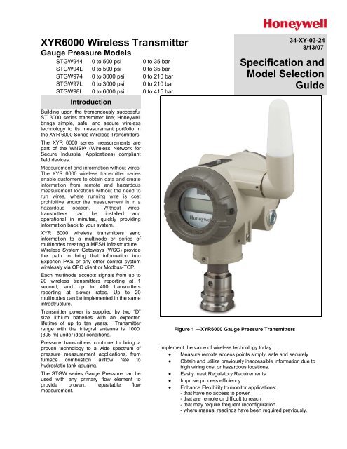
Figure 1 —<strong>XYR6000</strong> <strong>Gauge</strong> <strong>Pressure</strong> Transmitters<br />
Implement the value of wireless technology today:<br />
• Measure remote access points simply, safe and securely<br />
• Obtain and utilize previously inaccessible information due to<br />
high wiring cost or hazardous locations.<br />
• Easily meet Regulatory Requirements<br />
• Improve process efficiency<br />
• Enhance Flexibility to monitor applications:<br />
- that have no access to power<br />
- that are remote or difficult to reach<br />
- that may require frequent reconfiguration<br />
- where manual readings have been required previously.
34-XY-03-24<br />
Page 2<br />
<strong>Spec</strong>ifications<br />
Operating Conditions – All Models<br />
Parameter<br />
Reference<br />
Condition<br />
(at zero static)<br />
Rated Condition Operative Limits Transportation and<br />
Storage<br />
°C °F °C °F °C °F °C °F<br />
Ambient Temperature 25 ±1 77 ±2 -40 to 70 -40 to 158 -40 to 85 -40 to 185 -40 to 85 -40 to 185<br />
Meter Body Temperature 25 ±1 77 ±2 -40 to 110* -40 to 230* -40 to 125** -40 to 257** -40 to 85 -40 to 185<br />
Humidity %RH 10 to 55 0 to 100 0 to 100 0 to 100<br />
Vacuum Region - Minimum<br />
<strong>Pressure</strong><br />
mmHg absolute<br />
inH2O absolute<br />
atmospheric<br />
atmospheric<br />
25<br />
13<br />
2 (short term ***)<br />
1 (short term ***)<br />
Maximum Allowable<br />
Working <strong>Pressure</strong> (MAWP)<br />
(<strong>XYR6000</strong> products are rated to<br />
Maximum Allowable Working<br />
<strong>Pressure</strong>. MAWP depends on<br />
Approval Agency and transmitter<br />
materials of construction.))<br />
Vibration<br />
STGW944 and STGW94L = 500 psi, 35 bar<br />
STGW974 and STGW97L = 3000 psi, 210 bar<br />
STGW98L = 6000 psi, 415 bar<br />
Units can withstand overpressure of 1.5X MAWP without damage.<br />
Maximum of 4g over 15 to 200Hz.<br />
Shock Maximum of 40g.<br />
* For model 944 with CTFE fill fluid, the rating is –15 to 70°C (5 to 158°F); for model 98L with CTFE fill fluid,<br />
the rating is –15 to 110°C (5 to 230°F).<br />
** For Models STGW94L, STGW97L, and STGW98L the upper limit is 110°C (230°F).<br />
*** Short term equals 2 hours at 70°C (158 °F)<br />
Wireless <strong>Spec</strong>ifications<br />
Parameter<br />
Wireless Communication<br />
RF Transmitter Power<br />
Data<br />
Antennas<br />
Signal Range<br />
Description<br />
2,400 to 2,483.5 MHz (2.4 GHz) Frequency Hopping Spread <strong>Spec</strong>trum (FHSS)<br />
USA – FCC Certified<br />
Canada – IC Certified<br />
European Union – RTTE/ETSI Conformity<br />
125 mW (20.9 dBm) maximum per FCC/IC not including antenna, or 400 mW (26.0 dBm)<br />
maximum EIRP including antenna for USA and Canadian locations.<br />
100 mW (20.0 dBm) maximum EIRP per RTTE/ETSI including antenna for EU locations.<br />
Rate: 250 Kbps<br />
Integral – 2 dBi omnidirectional monopole<br />
Remote – 8 dBi omnidirectional monopole with up to 20 m cable and lightning surge arrester.<br />
Remote – 14 dBi Directional parabolic with up to 20 m cable and lightning surge arrester.<br />
Nominal 305 m (1,000 feet) between Field Transmitter and Infrastructure Unit (multinode) or<br />
Gateway Unit with a clear line of sight.*<br />
* Actual range will vary depending on antennas, cables and site topography.
Remote antenna<br />
34-XY-03-24<br />
Page 3
34-XY-03-24<br />
Page 4<br />
Performance Under Rated Conditions* - Models STGW944 & 94L (0 to 500 psi/35 bar)<br />
Parameter<br />
Description<br />
Upper Range Limit<br />
Minimum Span<br />
psi<br />
bar<br />
psi<br />
bar<br />
Zero Elevation and Suppression<br />
Accuracy (Reference – Includes<br />
combined effects of linearity,<br />
hysteresis, and repeatability)<br />
• Accuracy includes residual error<br />
after averaging successive<br />
readings.<br />
Zero Temperature Effect per<br />
28°C (50°F)<br />
Combined Zero and Span<br />
Temperature Effect per 28°C<br />
(50°F)<br />
500<br />
35<br />
20<br />
1.4<br />
No limit except minimum span from absolute 0 (zero) to +100% URL. <strong>Spec</strong>ifications<br />
valid over this range.<br />
±0.10% of calibrated span or upper range value (URV), whichever is greater, terminal<br />
based.<br />
For URV below reference point (20 psi), accuracy equals:<br />
± ⎛ 20 psi<br />
⎞<br />
0.10<br />
⎜<br />
⎟⎠<br />
⎝ span psi<br />
⎠<br />
1.4 bar<br />
± 0.10 or ± 0.10<br />
⎜<br />
⎟<br />
in % of span<br />
span<br />
bar<br />
±0.15% of span.<br />
For URV below reference point (50 psi), effect equals:<br />
⎛<br />
⎜<br />
⎝<br />
⎞<br />
⎟<br />
⎠<br />
50 psi<br />
3.5 bar<br />
± 0.15 or ± 0.15 ⎜ ⎟ in % of span<br />
span psi<br />
span bar<br />
±0.225% of span.<br />
For URV below reference point (50 psi), effect equals:<br />
±<br />
⎛<br />
⎝<br />
⎡ ⎛ 50 psi ⎞⎤<br />
⎡ ⎛ 3.5 bar ⎞⎤<br />
⎢0.075 + 0.15⎜<br />
⎟⎥<br />
or ±<br />
⎢<br />
+ 0.15⎜<br />
⎟⎥ ⎣ ⎝ span psi ⎠⎦<br />
⎣ ⎝ span bar ⎠ ⎦<br />
⎛<br />
⎝<br />
⎞<br />
⎠<br />
⎞<br />
⎠<br />
0.075 in % of span<br />
Stability<br />
±0.015% of URL per year<br />
* Performance specifications are based on reference conditions of 25°C (77°F), 10 to 55% RH, and 316L Stainless Steel barrier diaphragm.
34-XY-03-24<br />
Page 5<br />
Performance Under Rated Conditions* - Models STGW974 & 97L (0 to 3000 psi/210 bar)<br />
Parameter<br />
Description<br />
Upper Range Limit<br />
Minimum Span<br />
psi<br />
bar<br />
psi<br />
bar<br />
Zero Elevation and Suppression<br />
Accuracy (Reference – Includes<br />
combined effects of linearity,<br />
hysteresis, and repeatability)<br />
• Accuracy includes residual error<br />
after averaging successive<br />
readings.<br />
Zero Temperature Effect per<br />
28°C (50°F)<br />
Combined Zero and Span<br />
Temperature Effect per 28°C<br />
(50°F)<br />
Stability<br />
3000<br />
210<br />
300<br />
21<br />
No limit except minimum span from absolute 0 (zero) to +100% URL. <strong>Spec</strong>ifications<br />
valid over this range.<br />
±0.10% of calibrated span or upper range value (URV), whichever is greater, terminal<br />
based.<br />
For URV below reference point (750 psi), accuracy equals:<br />
⎛<br />
⎜<br />
⎝<br />
⎞<br />
⎟<br />
⎠<br />
750 psi<br />
52 bar<br />
± 0.10 or ± 0.10<br />
⎜<br />
⎟<br />
in % of span<br />
span<br />
psi<br />
⎝<br />
span<br />
bar<br />
⎠<br />
±0.20% of span.<br />
For URV below reference point (500 psi), effect equals:<br />
⎛<br />
⎜<br />
⎝<br />
⎞<br />
⎟<br />
⎠<br />
500 psi<br />
35 bar<br />
± 0.20 or ± 0.20 ⎜ ⎟ in % of span<br />
span psi<br />
span bar<br />
±0.30% of span.<br />
For URV below reference point (500 psi), effect equals:<br />
±<br />
⎛<br />
⎝<br />
⎡ ⎛ 500 psi ⎞⎤<br />
⎡ ⎛ 35 bar ⎞⎤<br />
⎢0.10 + 0.20⎜<br />
⎟⎥<br />
or ±<br />
⎢<br />
+ 0.20⎜<br />
⎟⎥ ⎣ ⎝ span psi ⎠⎦<br />
⎣ ⎝ span bar ⎠ ⎦<br />
±0.03% of URL per year<br />
⎛<br />
⎞<br />
⎠<br />
⎞<br />
0.10 in % of span<br />
* Performance specifications are based on reference conditions of 25°C (77°F), 10 to 55% RH, and 316L Stainless Steel barrier diaphragm.
34-XY-03-24<br />
Page 6<br />
Performance Under Rated Conditions* - Model STGW98L (0 to 6000 psi/415 bar)<br />
Parameter<br />
Description<br />
Upper Range Limit<br />
Minimum Span<br />
psi<br />
bar<br />
psi<br />
bar<br />
Zero Elevation and Suppression<br />
Accuracy (Reference – Includes<br />
combined effects of linearity,<br />
hysteresis, and repeatability)<br />
• Accuracy includes residual error<br />
after averaging successive<br />
readings.<br />
6000<br />
415<br />
500<br />
35<br />
No limit except minimum span from absolute 0 (zero) to +100% URL. <strong>Spec</strong>ifications<br />
valid over this range.<br />
±0.10% of calibrated span or upper range value (URV), whichever is greater, terminal<br />
based.<br />
For URV below reference point (1500 psi), accuracy equals:<br />
⎛<br />
⎜<br />
⎝<br />
⎞<br />
⎟<br />
⎠<br />
1500 psi<br />
104 bar<br />
± 0.10 or ± 0.10<br />
⎜<br />
⎟<br />
in % of span<br />
span<br />
psi<br />
⎝<br />
span<br />
bar<br />
⎠<br />
⎛<br />
⎞<br />
Zero Temperature Effect per<br />
28°C (50°F)<br />
Combined Zero and Span<br />
Temperature Effect per 28°C<br />
(50°F)<br />
Stability<br />
±0.20% of span.<br />
For URV below reference point (1500 psi), effect equals:<br />
⎛<br />
⎜<br />
⎝<br />
⎞<br />
⎟<br />
⎠<br />
1500 psi<br />
70 bar<br />
± 0.20 or ± 0.20 ⎜ ⎟ in % of span<br />
span psi<br />
span bar<br />
±0.30% of span.<br />
For URV below reference point (1500 psi), effect equals:<br />
±<br />
⎛<br />
⎝<br />
⎡ ⎛ 1500 psi ⎞⎤<br />
⎡ ⎛ 104 bar ⎞⎤<br />
⎢0.10 + 0.20⎜<br />
⎟⎥<br />
or ±<br />
⎢<br />
+ 0.20⎜<br />
⎟⎥ ⎣ ⎝ span psi ⎠⎦<br />
⎣ ⎝ span bar ⎠ ⎦<br />
±0.03% of URL per year<br />
⎞<br />
⎠<br />
0.10 in % of span<br />
* Performance specifications are based on reference conditions of 25°C (77°F), 10 to 55% RH, and 316L Stainless Steel barrier diaphragm.
34-XY-03-24<br />
Page 7<br />
Performance under Rated Conditions – General for all Models<br />
Parameter<br />
Description<br />
Lightning Surge Arrester<br />
(Remote antenna only)<br />
CE Conformity<br />
Hazardous Location<br />
Certifications<br />
Physical and Approval Bodies<br />
Parameter<br />
Frequency range: 0 – 3 GHz, 50 Ohms, VSWR = 1:1.3 Max, Insertion Loss = 0.4 dB<br />
Connectors Type N Female, Max, Gas Tube Element: 90 V ± 20%, Impulse Breakdown<br />
Voltage = 1,000 V ± 20%, Maximum Withstand Current = 5 KA.<br />
These transmitters are in conformity with the protection requirements of European<br />
Council Directives: 89/336/EEC, the EMC Directive and 1999/5/EC, the<br />
Telecommunications Directive per EN 300 328, V1.6.1 (2004-11), EN 300 489-1,<br />
V1.6.1 (2005-09), EN 300 489-3, V1.4.1 (2002-08) and EN 61326-1997+A1+A2,<br />
Electrical Equipment for Measurement, Control and Laboratory Use – EMC<br />
Requirements.<br />
See the Model Selection Guide.<br />
Description<br />
Barrier Diaphragm Material Dual-Head Meter Body: 316L SS, Hastelloy C-276, Monel 400, Tantalum<br />
In-Line Meter Body: 316L SS, Hastelloy C-276<br />
Process Head Material<br />
Dual-Head Meter Body: Carbon Steel (zinc-plated), 316 SS, Hastelloy C-276, Monel.<br />
[Standard reference head is Carbon Steel (zinc-plated). Optional reference head is 316<br />
SS.]<br />
In-Line Meter Body: 316L SS process interface.<br />
Head Gaskets<br />
Teflon is standard. Viton is available.<br />
Meter Body Bolting<br />
Carbon Steel (Zinc plated) standard. Options include 316 SS, NACE A286 SS bolts<br />
with 304 SS nuts, and B7M.<br />
Mounting Bracket<br />
Carbon Steel (Zinc-plated) or Stainless Steel angle bracket or Carbon Steel flat<br />
bracket available.<br />
Fill Fluid<br />
Silicone oil or CTFE (Chlorotrifluoroethylene)<br />
Electronic Housing<br />
Epoxy-Polyester hybrid paint. Low Copper-Aluminum. Meets NEMA 4X (hosedown and<br />
corrosion resistant), IP 66/67 (hosedown and submersible to 1m).<br />
Process Connections<br />
Dual-Head Meter Body: 1/4-inch F-NPT and DIN 19213 are standard. 1/2-inch F-NPT<br />
with optional adapter flange.<br />
In-Line Meter Body: 1/2-inch F-NPT, 1/2 inch M-NPT, 9/16 AMINCO, DIN 19213<br />
Mounting<br />
Can be mounted in virtually any position using the standard mounting bracket.<br />
Mounting should result in the antenna being vertically oriented. Bracket is designed to<br />
mount on 2-inch (50 mm) vertical or horizontal pipe. See Figure 2 and Figure 3.<br />
Dimensions See Figure 4 through Figure 7.<br />
Net Weight<br />
With Dual-Head Meter Body: 11 pounds (5 Kg)<br />
With In-Line Meter Body: 7 pounds (3.2 Kg)<br />
NOTE: <strong>Pressure</strong> transmitters that are part of safety equipment for the protection of piping (systems) or vessel(s) from<br />
exceeding allowable pressure limits, (equipment with safety functions in accordance with <strong>Pressure</strong> Equipment Directive<br />
97/23/EC article 1, 2.1.3), require separate examination.
34-XY-03-24<br />
Page 8<br />
Figure 2—Examples of typical mounting positions for dual-head models STGW944 and STGW974<br />
Figure 3 —Examples of typical mounting positions for in-line models STGW94L, STGW97L, STGW98L, STAW94L.<br />
Note that a mounting bracket is not required for in-line models.
34-XY-03-24<br />
Page 9<br />
Reference Dimensions: millimeters<br />
inches<br />
Figure 4 —Typical dimensions for dual-head models STGW944 and STGW974 (side view)
34-XY-03-24<br />
Page 10<br />
240,80<br />
9.48<br />
Figure 5 —Typical dimensions for dual-head models STGW944 and STGW974 (rear view)
34-XY-03-24<br />
Page 11<br />
Reference Dimensions: millimeters<br />
inches<br />
Figure 6—Typical mounting dimensions for in-line models STGW94L, STGW97L, STGW98L, and STGW99L
34-XY-03-24<br />
Page 12<br />
Figure 7—Typical mounting dimensions for in-line models STGW94L, STGW97L, STGW98L, and STGW99L (rear view)
34-XY-03-24<br />
Page 13<br />
Options<br />
Ordering Information<br />
Mounting Bracket<br />
The angle mounting bracket is<br />
available in either zinc-plated<br />
carbon steel or stainless steel and<br />
is suitable for horizontal or vertical<br />
mounting on a two inch (50<br />
millimeter) pipe, as well as wall<br />
mounting. An optional flat<br />
mounting bracket is also available<br />
in carbon steel for two inch (50<br />
millimeter) pipe mounting.<br />
Transmitter Configuration<br />
All configurable parameters are<br />
accessible via the WNSIA network<br />
via READ/WRITE transactions.<br />
I<br />
Tagging (Option TG)<br />
Up to 30 characters can be added<br />
on the stainless steel nameplate<br />
mounted on the transmitter’s<br />
electronics housing at no extra cost.<br />
A stainless steel wired on tag with<br />
additional data of up to 4 lines of 28<br />
characters is also available. The<br />
number of characters for tagging<br />
includes spaces.<br />
Contact your nearest <strong>Honeywell</strong> sales<br />
office, or<br />
In the U.S.:<br />
<strong>Honeywell</strong><br />
Industrial Automation & Control<br />
2500 W. Union Hills Ave<br />
Phoenix, AZ 85053<br />
1-800-288-7491<br />
In Canada:<br />
The <strong>Honeywell</strong> Centre<br />
155 Gordon Baker Rd.<br />
North York, Ontario M2H 3N7<br />
1-800-461-0013<br />
In Latin America:<br />
<strong>Honeywell</strong> Inc.<br />
480 Sawgrass Corporate Parkway,<br />
Suite 200<br />
Sunrise, FL 33325<br />
(954) 845-2600<br />
In Europe and Africa:<br />
<strong>Honeywell</strong> S. A.<br />
Avenue du Bourget 1<br />
1140 Brussels, Belgium<br />
In Eastern Europe:<br />
<strong>Honeywell</strong> Praha,<br />
s.r.o. Budejovicka 1<br />
140 21 Prague 4,<br />
Czech Republic<br />
In the Middle East:<br />
<strong>Honeywell</strong> Middle East Ltd.<br />
Khalifa Street,<br />
Sheikh Faisal Building<br />
Abu Dhabi, U. A. E.<br />
In Asia:<br />
<strong>Honeywell</strong> Asia Pacific Inc.<br />
<strong>Honeywell</strong> Building,<br />
17 Changi Business Park Central 1<br />
Singapore 486073<br />
Republic of Singapore<br />
In the Pacific:<br />
<strong>Honeywell</strong> Pty Ltd.<br />
5 Thomas Holt Drive<br />
North Ryde NSW Australia 2113<br />
(61 2) 9353 7000<br />
<strong>Spec</strong>ifications are subject to change without notice.<br />
In Japan:<br />
<strong>Honeywell</strong> K.K.<br />
14-6 Shibaura 1-chrome<br />
Minato-ku, Tokyo, Japan 105-0023<br />
Or, visit <strong>Honeywell</strong> on the World Wide<br />
Web at: http://www.honeywell.com
34-XY-03-24<br />
Page 14<br />
Model Selection Guide (34-XY-16-34)<br />
Model Selection Guide<br />
34-XY-16-34 Issue 2<br />
Instructions<br />
Select the desired Key Number. The arrow to the right marks the selection available.<br />
Make one selection from each table, I and II, using the column below the proper arrow.<br />
Select as many Table III options as desired (if no options or approvals are desired, specify 9X).<br />
A (•) denotes unrestricted availability. A letter denotes restricted availability.<br />
Restrictions follow Table V.<br />
Key Number I II III<br />
IV V<br />
STGW_ _ _ - _ _ _ - 00000 - _ _ _ _ _ - _ _, _ _, _ _ - XXXX<br />
KEY NUMBER<br />
Gage<br />
<strong>Pressure</strong><br />
Span<br />
0-20 to 0-500 psi/0-1.4 to 0-35 bar<br />
0-300 to 0-3000 psi/0-21 to 0-210 bar<br />
Selection<br />
STGW944<br />
STGW974<br />
Availability<br />
TABLE I - METER BODY<br />
Wetted Vent/Drain Barrier<br />
Process Head *** Valve ** Diaphragms<br />
Selection<br />
Carbon Steel * 316 SS 316L SS<br />
A _ _<br />
Carbon Steel * 316 SS Hastelloy C<br />
B _ _<br />
Carbon Steel * 316 SS Monel<br />
C _ _<br />
Carbon Steel * 316 SS Tantalum<br />
D _ _<br />
316 SS 316 SS 316L SS<br />
E _ _<br />
Materials of 316 SS 316 SS Hastelloy C<br />
F _ _<br />
Construction 316 SS 316 SS Monel<br />
G _ _<br />
316 SS 316 SS Tantalum<br />
H _ _<br />
Hastelloy C Hastelloy C Hastelloy C<br />
J _ _<br />
Hastelloy C Hastelloy C Tantalum<br />
K _ _<br />
Monel<br />
Monel<br />
Monel<br />
L _ _<br />
Fill Fluid<br />
Silicone DC200 ****<br />
_ 1 _<br />
CTFE<br />
_ 2 _<br />
Process Head<br />
Configuration<br />
1/4" NPT<br />
1/2" NPT with Adapter<br />
_ _ A<br />
_ _ G<br />
•<br />
•<br />
•<br />
•<br />
•<br />
•<br />
•<br />
•<br />
•<br />
•<br />
•<br />
•<br />
•<br />
•<br />
k<br />
TABLE II<br />
No Selection<br />
00000<br />
•<br />
* Carbon Steel heads are zinc-plated. Not recommended for water service due to hydrogen migration.<br />
Use Stainless Steel heads.<br />
** Vent/Drains are Teflon coated for lubricity.<br />
*** The standard reference head for the STGW9XX is carbon steel (zinc-plated).<br />
See Table III for a stainless steel reference (HR) head option.<br />
Note:<br />
End vent drain valve standard for STGW9XX.
TABLE III - ANTENNA OPTIONS Selection Availability<br />
Antenna's Integral Right-angle, vertical (Standard) V _ _ _ _ d<br />
Integral Straight, horizontal<br />
S _ _ _ _ d<br />
Remote Omnidirectional, 8 dBi<br />
M _ _ _ _ e<br />
Remote Directional, 14 dBi<br />
D _ _ _ _ e<br />
Cable A for None _ 0 0 _ _ •<br />
Remote Antenna 1.0m remote Cable A, TNC-R - N (Req'd to connect to XYR 6000) _ 0 1 _ _ •<br />
3.0m remote Cable A, TNC-R - N (Req'd to connect to XYR 6000) _ 0 3 _ _ •<br />
10.0m remote Cable A, TNC-R - N (Req'd to connect to XYR 6000) _ 1 0 _ _ •<br />
Lightning Protection None _ _ _ 0 0 •<br />
for remote Antenna Lightning Protection + 1.0m Cable B to Antenna, N - N _ _ _ 0 1 •<br />
With Cable B Lightning Protection + 3.0m Cable B to Antenna, N - N _ _ _ 0 3 •<br />
Lightning Protection + 10.0m Cable B to Antenna, N - N<br />
_ _ _ 1 0 •<br />
34-XY-03-24<br />
Page 15<br />
TABLE IV - OPTIONS<br />
None<br />
00 •<br />
Transmitter Housing & Electronics Options<br />
Custom Calibration and I.D. in Memory<br />
CC •<br />
Transmitter Configuration and ID in Memory<br />
TC •<br />
M20 Conduit Thread (1/2" NPT is standard)<br />
A1 •<br />
1/2" NPT to 3/4" NPT 316 SS Conduit Adapter A2 •<br />
b<br />
Stainless Steel Customer Wired-On Tag<br />
TG •<br />
(4 lines, 28 characters per line, customer supplied information) b<br />
Stainless Steel Customer Wired-On Tag (blank)<br />
TB •<br />
End Cap Warning Label in Spanish<br />
SP •<br />
End Cap Warning Label in Portuguese PG • b<br />
End Cap Warning Label in Italian<br />
TL •<br />
End Cap Warning Label in German<br />
GE •<br />
Meter Body Options<br />
A286 SS (NACE) Bolts and 304 SS (NACE) Nuts for Process Heads<br />
CR •<br />
316 SS Bolts and 316 SS Nuts for Process Heads SS • b<br />
B7M Bolts and Nuts for Process Heads<br />
B7 •<br />
316 SS Adapter Flange - 1/2" NPT with CS Bolts S2 c<br />
316 SS Adapter Flange - 1/2" NPT with 316 SS Bolts S3 c<br />
316 SS Adapter Flange - 1/2" NPT with NACE A286 SS Bolts S4 c<br />
316 SS Adapter Flange - 1/2" NPT with B7M Bolts S5 c<br />
Hastelloy C Adapter Flange - 1/2" NPT with CS Bolts T2 c b<br />
Hastelloy C Adapter Flange - 1/2" NPT with 316 SS Bolts<br />
T3 c<br />
Monel Adapter Flange - 1/2" NPT with CS Bolts<br />
V2 c<br />
Monel Adapter Flange - 1/2" NPT with 316 SS Bolts<br />
V3 c<br />
316 SS Blind Adapter Flange with CS Bolts B3 •<br />
316 SS Blind Adapter Flange with 316 SS Bolts B4 •<br />
316 SS Blind Adapter Flange with NACE A286 SS Bolts B5 • b<br />
316 SS Blind Adapter Flange with B7M Bolts B6 •<br />
316 SS Center Vent Drain and Bushing CV •<br />
Side Vent/Drain (End Vent Drain is standard)<br />
SV •<br />
Viton Process Head Gaskets<br />
VT •<br />
Viton Adapter Flange Gaskets<br />
VF •<br />
316 SS Reference Head (Carbon Steel Standard) HR •<br />
Graphite Process Head Gasket<br />
GF •<br />
Transmitter Mounting Bracket Options<br />
Mounting Bracket - Carbon Steel<br />
MB •<br />
Mounting Bracket - 304 SS SB • b<br />
Flat Mounting Bracket - Carbon Steel<br />
FB •<br />
Diaphragm Options<br />
Gold plated diaphragm(s) on 316 SS<br />
G1 •<br />
Gold plated diaphragm(s) on Monel or Hastelloy ONLY<br />
G2 •<br />
b<br />
Table IV continued next page
34-XY-03-24<br />
Page 16<br />
TABLE IV - OPTIONS (Continued) Selection Availability<br />
Services/Calibration/Conformance Options<br />
User's Manual Paper Copy UM •<br />
Clean Transmitter for Oxygen or Chlorine Service with Certificate 0X h<br />
Over-<strong>Pressure</strong> Leak Test with F3392 Certificate TP •<br />
Calibration Test Report and Certificate of Conformance (F3399) F1 •<br />
Certificate of Conformance (F3391) F3 •<br />
b<br />
Certificate Options<br />
Certificate of Origin (F0195) F5 •<br />
NACE Certificate (F0198) F7 i<br />
Warranty Options<br />
Additional Warranty - 1 year W1 •<br />
Additional Warranty - 2 years W2 •<br />
b<br />
Approval<br />
Body Approval Type Location or Classification<br />
No hazardous location approvals<br />
9X •<br />
Nonincendive Nonincendive, CL I, Div 2, Groups A,B,C & D,<br />
CSA<br />
CL II & III, Div 2, Groups F & G, T4 Ta = 85°C<br />
2N •<br />
cus Non-Sparking Class I, Ex/AEx nC IIC; T4, Ta ≤ 85°C, Zone 2; b<br />
IP 66<br />
ATEX<br />
Non-Sparking Ex II 3 GD; Ex nL IIC; T4, Ta ≤ 85°C, Zone 2;<br />
IP 66/67<br />
3N •<br />
WARNING – Division 2 / Zone 2 apparatus may only be connected to processes classified as non-hazardous<br />
or Division 2 / Zone 2. Connection to hazardous (flammable or ignition capable) Division 1 / Zone 0, or 1<br />
process is not permitted.<br />
TABLE V<br />
Factory Identification XXXX •<br />
RESTRICTIONS<br />
Restriction<br />
Letters Table<br />
Available Only With<br />
Selection Table<br />
b<br />
c I<br />
Select only one option from this group<br />
_ _ G<br />
III<br />
_ 00 _ _<br />
d<br />
e<br />
h<br />
III<br />
I<br />
_ _ _ 00<br />
_ 2 _<br />
III<br />
i IV CR, S4, B5<br />
k IV<br />
Select from Table IV<br />
S2, S3, S4, S5, T2, T3, V2, V3<br />
Not Available With<br />
Selection<br />
_ 00 _ _<br />
Notes: See ST-89 for Published <strong>Spec</strong>ials with pricing.<br />
See ST-95 and User's Manual for part numbers.<br />
To request a quotation for a non-published "special", fax RFQ to 602-313-6155 or<br />
email to ace@honeywell.com
34-XY-03-24<br />
Page 17<br />
OneWireless and XYR are trademarks and Experion is a registered trademark of <strong>Honeywell</strong> International Inc.<br />
<strong>Honeywell</strong> Field Solutions<br />
<strong>Honeywell</strong> International Inc.<br />
2500 W. Union Hills Dr.<br />
Phoenix, Arizona 85027<br />
©<strong>Honeywell</strong> International Inc.


