TAHITI DUAL HC - HR - Portsdean Technical
TAHITI DUAL HC - HR - Portsdean Technical
TAHITI DUAL HC - HR - Portsdean Technical

You also want an ePaper? Increase the reach of your titles
YUMPU automatically turns print PDFs into web optimized ePapers that Google loves.
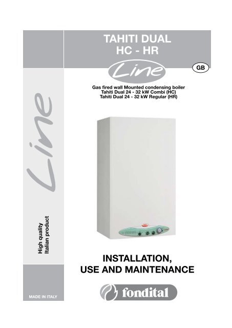
<strong>TAHITI</strong> <strong>DUAL</strong><br />
<strong>HC</strong> - <strong>HR</strong><br />
GB<br />
Gas fired wall Mounted condensing boiler<br />
Tahiti Dual 24 - 32 kW Combi (<strong>HC</strong>)<br />
Tahiti Dual 24 - 32 kW Regular (<strong>HR</strong>)<br />
High quality<br />
Italian product<br />
INSTALLATION,<br />
USE AND MAINTENANCE<br />
MADE IN ITALY
Natural Gas<br />
Fondital Tahiti Dual <strong>HC</strong> 24 kW Line Combi (<strong>HC</strong>)<br />
G.C.N° 47 309 04<br />
Fondital Tahiti Dual <strong>HR</strong> 24 kW Line Regular (<strong>HR</strong>)<br />
G.C.N° 47 309 05<br />
Fondital Tahiti Dual <strong>HC</strong> 32 kW Line Combi (<strong>HC</strong>)<br />
G.C.N° xx xxx xx<br />
Fondital Tahiti Dual <strong>HR</strong> 32 kW Line Regular (<strong>HR</strong>)<br />
G.C.N° xx xxx xx<br />
Benchmark places responsibilities on both manufacturers and installers. The purpose is to ensure that customers are provided with the<br />
correct equipment for their needs, that it is installed, commissioned and serviced in accordance with the manufacturer’s instructions by<br />
competent persons and that it meets the requirements of the appropriate Building Regulations. The Benchmark Checklist can be used to<br />
demonstrate compliance with Building Regulations and should be provided to the customer for future reference.<br />
Installers are required to carry out installation, commissioning and servicing work in accordance with the Benchmark Code of Practice<br />
which is available from the Heating and Hotwater Industry Council who manage and promote the Scheme.<br />
Visit www.centralheating.co.uk for more information.
Dear Customer,<br />
Thank You for choosing and buying one of our boilers.<br />
Please read these instructions carefully in order to properly install, operate, and maintain the equipment.
1. General information for fitters, maintenance technicians and users<br />
1.1. General warnings<br />
This INSTRUCTION MANUAL, which is an integral and indispensable part of the product, must be handed over to the user by the installer<br />
and must be kept in a safe place for future reference. The manual must accompany the boiler should it be sold or its possession<br />
transferred. Following to the boiler installation, the fitter is to advise the user about boiler operation and its safety devices. This Manual<br />
must be left along with the Benchmark commissioning booklet with the boiler as Regulation 29 of the HSC Gas safety (installation and<br />
use) Regulations 1998.<br />
<br />
This boiler is designed for connection to a domestic heating or hot water system.<br />
Any other use is deemed as improper and as such dangerous. Under no circumstances will the manufacturer be held<br />
responsible for damage or injury to persons or animals caused by errors in the installation and/or use of the appliance,<br />
or through non-compliance with current local and national standards and/or the manufacturer’s instructions.<br />
The boiler must be installed by qualified personnel, in compliance with applicable laws and standards and according to the<br />
manufacturer’s instructions given in this manual.<br />
In GB, the installation must be carried out by a Registered Installer. To check for authorised qualified engineers please contact<br />
CORGI 01256 372400. It must be carried out in accordance with the relevant requirements of the:<br />
• Gas Safety Regulations;<br />
• The appropriate Building Regulations either The Building Regulation, The Building Regulations (Scotland), Building Regulations<br />
(Northern Ireland);<br />
• The Water Fittings Regulations or Water Bylaws in Scotland;<br />
• The current I.E.E. Wiring Regulations.<br />
Where no specific instructions are given, reference should be made to the relevant British Standards Code of Practice.<br />
In IE, the installation must be carried out by a competent Person and installed in accordance with the current edition of I.E. 813<br />
“Domestic Gas Installations”, the current Building Regulations and reference should be made to the current ETCI rules for electrical<br />
installations.<br />
The commissioning of the boiler and any subsequent works carried out on the appliance must be effected by an appropriately qualified<br />
technician or an approved Fondital Helpline Service Centre.<br />
Damage and/or injury caused by incorrect installation or use and/or damage and/or injury due to non-observance of the manufacturer’s<br />
instructions shall relieve the manufacturer from any and all contractual and extra-contractual liability.<br />
Before installing the boiler, check that the technical data correspond to the requirements for its correct use in the system.<br />
Check that the boiler is intact and it has not been damaged during transport and handling: do not install equipment which is damaged<br />
and/or faulty. In case of doubt, do not attempt to use the product but refer to the supplier. Packing materials (cardboard box, wooden<br />
crate, nails, staples, plastic bags, polystyrene, etc.) must not be left within reach of children in that these items represent a potential<br />
hazard and must be disposed of in a responsible manner.<br />
Do not obstruct the air intake or flue exhaust grills and terminals.<br />
Only manufacturer approved and supplied accessories or optional kits (including electric ones) are to be installed.<br />
Properly dispose of the packaging as all the materials can be recycled. The packaging must therefore be sent to specific waste<br />
management sites.<br />
In the event of failure and/or malfunction, shut down the system. Do not interfere with or attempt any repairs. Call for professionally<br />
qualified technical assistance only. Fondital helpline UK 08700 34 8820.<br />
Any warranty repairs to the appliance must be carried out exclusively by the manufacturer’s authorised service centre using original<br />
spare parts. Non-observance of the above requirements may affect the safety of the boilers and endanger people, animals and property.<br />
The manufacturer, in order to guarantee efficient and correct functioning of the equipment, recommends the boiler to be serviced and<br />
repaired by an authorized Service Centre which is best trained for the purpose.<br />
Before carrying out any cleaning or maintenance operations, disconnect the appliance from the mains electricity supply by switching off<br />
at the main switch and/or any other isolating device.<br />
Routine boiler maintenance is to be performed according to the schedule indicated in the relevant section of this<br />
manual. Appropriate boiler maintenance ensures efficient operation, environment preservation, and safety for people,<br />
animals and objects.<br />
In the event of long periods of inactivity of the boiler, disconnect it from power mains and close the gas tap. Warning!<br />
When power mains are disconnected, boiler electronic anti-freeze function will not be operative.<br />
Should there be a risk of freezing, add anti-freeze: it is not advisable to empty the system as this may result in damage; use specific<br />
anti-freeze products suitable for multi-metal heating systems.
Should you smell gas:<br />
- do not turn on or off electric switches and do not turn on electric appliances;<br />
- do not ignite flames and do not smoke;<br />
- close the main gas tap;<br />
- open doors and windows;<br />
- contact a Service Centre, a qualified installer or the gas supply company.<br />
Never use flames to detect gas leaks.<br />
NATIONAL GRID GAS EMERGENCY 0800 111 999<br />
The boiler is designed for installation in the country indicated on the technical data plate: installation in any other<br />
country may be source of danger for people, animals and objects.<br />
The “operating instructions” of this manual must be read carefully as it provides information on the operating and the operating limits of<br />
the appliance.<br />
This appliance must be used exclusively in an un-vented central heating system.<br />
The warnings contained in this chapter have been written for the appliance user, the installer and the service engineer.<br />
1.2. Product conformity<br />
FONDITAL S.p.a. declare that all its products are manufactured to a high specification and in compliace with the relevant standards.<br />
All FONDITAL boilers are CE certified and possess technical and functional characteristics that comply with the following standards:<br />
UNI EN 297 for GAS-FIRED CENTRAL HEATING BOILERS TYPE B OF NOMINAL HEAT INPUT ≤ 70 kW<br />
EN 483 for GAS-FIRED CENTRAL HEATING BOILERS TYPE C OF NOMINAL HEAT INPUT ≤ 70 kW<br />
UNI EN 677 for GAS-Fired CENTRAL HEATING BOILERS. SPECIFIC REQUIREMENTS FOR CONDENSING BOILERS WITH NOMINAL<br />
HEAT INPUT ≤ 70 kW<br />
Gas fired boilers also comply with the following directives:<br />
GAS APPLIANCES DIRECTIVE 90/396 CEE for CE compliance<br />
LOW VOLTAGE DIRECTIVE 2006/95 CE<br />
BOILER EFFICIENCY DIRECTIVE 92/42 CE<br />
ELECTROMAGNETIC COMPATIBILITY DIRECTIVE 89/336 CE<br />
The materials used such a copper, brass, stainless steel, etc. form a compact, homogeneous, highly functional unit that is easy to install<br />
and simple to operate. In its simplicity, the wall-mounted appliance is equipped with all the appropriate accessories required to make it a<br />
fully independent boiler capable of satisfying domestic hot water production and central heating needs. All boilers are fully inspected and<br />
are accompanied by a quality certificate, signed by the inspector, and a guarantee certificate. This manual must be kept in a safe place<br />
and must accompany the boiler at all times.<br />
FONDITAL S.p.a. will not be held responsible for any misinterpretation of this manual resulting from the inaccurate translation of<br />
same.<br />
FONDITAL S.p.a. will not be held responsible for the consequences in the case of non observance of the instructions contained<br />
in this manual or in the case where actions not specifically described herein are undertaken.<br />
FONDITAL S.p.a. declare that no substances harmful to health are contained in the appliance or used during appliance<br />
manufacture and have not used or intend to use any of the following substances in the manufacture of Fondital heating<br />
products:<br />
- Asbestos<br />
- Mercury<br />
- CFC’s<br />
It is a condition of the manufacturers warranty that the Benchmark Commissioning Checklist is fully<br />
completed and left with the appliance.
CONTEST<br />
1. General information for fitters, maintenance technicians and users pag. 4<br />
1.1. General warnings pag. 4<br />
1.2. Product conformity pag. 5<br />
2. Instructions for the user pag. 7<br />
2.1 Control panel pag. 7<br />
2.2 Operating the boiler pag. 9<br />
2.2.1. Switching on pag. 9<br />
2.2.2. CH function pag. 9<br />
2.2.3. DHW function pag. 10<br />
2.2.4. ANTI-FREEZE function pag. 10<br />
2.2.5. PUMP AND T<strong>HR</strong>EE-WAY VALVE ANTI-SEIZE FUNCTION pag. 10<br />
2.2.6. External probe operation (optional equipment) pag. 10<br />
2.3. Boiler lockout pag. 11<br />
2.3.1. Burner lockout pag. 11<br />
2.3.2. Shut-down due to overheating pag. 11<br />
2.3.3. Shut-down due to inadequate air/flue gas draught pag. 11<br />
2.3.4. Shut-down due to low water pressure pag. 12<br />
2.3.5. Shut-down due to temperature probe malfunction pag. 12<br />
2.4. Maintenance pag. 12<br />
2.5. Notes for the user pag. 12<br />
3. <strong>Technical</strong> characteristics and dimensions pag. 13<br />
3.1. Dimensions pag. 14<br />
3.2. Layout pag. 15<br />
3.3. Operating data pag. 16<br />
3.4. General characteristics pag. 16<br />
4. Instructions for the fitter pag. 17<br />
4.1. Reference standard pag. 17<br />
4.2. System details pag. 18<br />
4.2.1. Central heating circuit pag. 18<br />
4.2.2. Filling the central heating system pag. 18<br />
4.2.3. Domestic hot water circuit pag. 19<br />
4.3. Site requirements pag. 19<br />
4.3.1. Choosing where to install the boiler pag. 19<br />
4.3.2. Positioning the boiler pag. 19<br />
4.3.3. Boiler room ventilation pag. 21<br />
4.3.4. Flue pag. 21<br />
4.4. Installation (authorised personnel) pag. 22<br />
4.4.1. Packaging pag. 22<br />
4.4.2. Installing the boiler pag. 22<br />
4.4.3. Gas main connection pag. 22<br />
4.4.4. Hydraulic connections pag. 23<br />
4.4.5. Adjustable by-pass pag. 25<br />
4.5. Flue options pag. 25<br />
4.5.1. Air intake/flue gas discharge system pag. 25<br />
4.5.2. Configuration of air/flue system pipes pag. 26<br />
4.5.3. Ø 100/60 mm air/flue gas coaxial duct system pag. 27<br />
4.5.4. Ø 80 mm air/flue gas split duct system pag. 28<br />
4.5.5. Electrical supply connection pag. 31<br />
4.5.6. Room thermostat connection (optional equipment) pag. 31<br />
4.5.7. External temperature probe installation (optional equipment) and “sliding temperature” operation pag. 31<br />
4.5.8. Installation of the OPENTHERM remote control (optional equipment only for <strong>HR</strong> model) pag. 33<br />
4.5.9. Loading the system pag. 33<br />
4.6. Burner adjustment pag. 34<br />
5. Commissioning pag. 35<br />
5.1. Commissioning the boiler pag. 35<br />
5.2. Setting the timer pag. 35<br />
5.3. Checking pag. 35<br />
5.4. Switching on and switching off pag. 35<br />
6. Servicing pag. 36<br />
6.1. General warnings pag. 36<br />
6.2. Boiler inspection pag. 36<br />
6.3. Servicing schedule pag. 36<br />
6.4. Analysis of combustion parameters pag. 36<br />
6.5. Testing combustion efficiency pag. 37<br />
6.5.1. “Chimney sweep” function pag. 37<br />
6.5.2. Measurements pag. 37<br />
6.6. Wiring diagram pag. 38<br />
6.7 Hydraulic loss pag. 39<br />
7. Spare part list pag. 40<br />
8. Troubleshooting pag. 44<br />
Benchmark Commissioning checklist pag. 46
2. Instructions for the user<br />
Fondital is a licensed member of the Benchmark Scheme which aims to improve the standards of installation and commissioning of<br />
domestic heating and hot water systems in the UK and to encourage regular servicing to optimise safety, efficiency and performance.<br />
Benchmark is managed and promoted by the Heating and Hotwater Industry Council.<br />
For more information visit www.centralheating.co.uk<br />
Please ensure that the installer has fully completed the Benchmark Checklist on the inside back pages of the installation instructions<br />
supplied with the product and that you have signed it to say that you have received a full and clear explanation of its operation. The<br />
installer is legally required to complete a commissioning checklist as a means of complying with the appropriate Building Regulations<br />
(England and Wales).<br />
All installations must be notified to Local Area Building Control either directly or through a Competent Persons Scheme. A Building Regulations<br />
Compliace Certificate will then be issued to the customer who should, on receipt, write the Notification Number on the Benchmark<br />
Checklist.<br />
This product should be serviced regularly to optimise its safety, efficiency and performance. The service engineer should complete the<br />
relevant Service Record on the Benchmark Checklist after each service.<br />
The Benchmark Checklist may be required in the event of any warranty work and as supporting documentation relating to home improvements<br />
in the optional documents section of the Home Information Pack.<br />
2.1. Control panel<br />
1 2 3 4 5 6 7 8 9 10 11 12<br />
pic. 1<br />
1. Power mains connection light (green)<br />
This light indicates that the power supply to the boiler is on.<br />
2. Indicator light (red)<br />
When this light is on, it means the temperature of the water in the heating system is between 25°C and 35°C.<br />
When this light is flashing, it means the boiler has shut down due to a malfunction.<br />
3. Indicator light (red)<br />
When this light is on, it means the temperature of the water in the heating system is between 36°C and 45°C. When this light is flashing,<br />
it means the boiler’s safety thermostat has shut the boiler down.<br />
4. Indicator light (red)<br />
When this light is on, it means the temperature of the water in the heating system is between 46°C and 55°C.<br />
When this light is flashing, it means there is a fault in the air intake and/or flue discharge piping.<br />
5. Indicator light (red)<br />
When this light is on, it means the temperature of the water in the heating system is between 56°C and 65°C.<br />
When this light is flashing, it means the burner has shut down.<br />
6. Indicator light (red)<br />
When this light is on, it means the temperature of the water in the heating system is between 66°C and 75°C.<br />
When this light is flashing, it means the water pressure in the boiler is too low.<br />
7. Indicator light (red)<br />
When this light is on, it means the temperature of the water in the heating system is between 76°C and 85°C.<br />
When this light is flashing, it means the CH temperature is above 85°C.<br />
8. Indicator light (yellow)<br />
When this light is on, it means the flame is present on the burner.<br />
When this light is flashing, it means the boiler has shut down due to a malfunction.
9. Boiler mode<br />
When the knob is in the OFF position the boiler is in stand-by mode.<br />
When the knob is in the SUMMER position , the boiler supplies DHW only.<br />
When the knob is in the WINTER position , the boiler supplies both CH and DHW.<br />
When the knob is in the ANTI-FREEZE position , only the boiler anti-freeze function is active.<br />
When the knob is turned to the RESET position and back , the boiler resumes operation.<br />
10. DHW temperature regulator<br />
This knob is used to set the DHW temperature within the range 35 - 57°C<br />
WARNING<br />
The boiler has a special built-in regulator that limits DHW flow up to 10 litres per minute. In addition to the DHW temperature set on this<br />
regulator, the DHW temperature also depends on the amount of water requested by the user and the supply temperature.<br />
11. CH temperature adjustment<br />
This knob is used to set the temperature of the water in the heating system. The setting range is 35 - 78°C.<br />
12. Time clock<br />
The time clock is for central heating control only. The clock is provided with a selector switch with three positions:<br />
a) Position “I” CONSTANT: in this position, the clock circuit is always closed (switch on), therefore the boiler will constantly on and<br />
will only shut off upon the request of the room thermostat (if installed) or the heating thermostat;<br />
b) Position “O” HEATING OFF: in this position, the clock circuit is always open (switch off) and the boiler will therefore never<br />
igniter for heating, Domestic hot water will operate on demand;<br />
c) “Central” position PROGRAMMING ACTIVE: in this position, the programming set by the user is active.<br />
Using the three position switch the timer will allow either constant operation, timed operation or central heating off. Move the switch<br />
bottom by sliding to the desired position.<br />
The time clock is provided with 72 switches, each of which cover a time interval of 20 minutes (three per hour).<br />
Tapped position<br />
ON<br />
OFF<br />
When a rider is switched from the outside (on setting) to the inside of the clock border (off setting),<br />
the circuit is open (switch off) for a period of 20 minutes and then the boiler stops.<br />
For set the time of day, turn the timer outer bezel clockwise, to align the pointer with the correct<br />
time to the nearest 20 minutes. Do not at any time attempt to turn the bezel anti-clockwise.<br />
For set the timed heating program, decide which times of the day the central heating is required.<br />
The heating will operate when the green tappets are set to the outer edge of the bezel.<br />
To ensure the heating stays OFF set the required tappets inwards towards the centre of the bezel.
COLOUR DISPLAY ACCORDING TO BOILER STATUS<br />
Regular working LIGHT 1 LIGHT 2 LIGHT 3 LIGHT 4 LIGHT 5 LIGHT 6 LIGHT 7 LIGHT 8<br />
Power connected to boiler GREEN n/a n/a n/a n/a n/a n/a n/a<br />
Burner on GREEN n/a n/a n/a n/a n/a n/a YELLOW<br />
CH temperature < 25°C GREEN OFF OFF OFF OFF OFF OFF n/a<br />
26°C < CH temperature < 35°C GREEN RED OFF OFF OFF OFF OFF n/a<br />
36°C < CH temperature < 45°C GREEN OFF RED OFF OFF OFF OFF n/a<br />
46°C < CH temperature < 55°C GREEN OFF OFF RED OFF OFF OFF n/a<br />
56°C < CH temperature < 65°C GREEN OFF OFF OFF RED OFF OFF n/a<br />
66°C < CH temperature < 75°C GREEN OFF OFF OFF OFF RED OFF n/a<br />
76°C < CH temperature < 85°C GREEN OFF OFF OFF OFF OFF RED n/a<br />
Table 1 - Colour displayed by Light in relation to boiler operation status<br />
Malfunctions LIGHT 1 LIGHT 2 LIGHT 3 LIGHT 4 LIGHT 5 LIGHT 6 LIGHT 7 LIGHT 8<br />
Power is missing OFF OFF OFF OFF OFF OFF OFF OFF<br />
Safety thermostat shutdown GREEN OFF RED L OFF OFF OFF OFF OFF<br />
Air/flue gas pressure switch<br />
GREEN OFF OFF RED L OFF OFF OFF OFF<br />
shutdown<br />
Shutdown due to flame absence GREEN OFF OFF OFF RED L OFF OFF OFF<br />
Water pressure switch shutdown GREEN OFF OFF OFF OFF RED L OFF OFF<br />
Gas valve alarm GREEN OFF RED L OFF OFF OFF OFF YELLOW L<br />
Water temperature switch alarm (>85°C) GREEN OFF OFF OFF OFF OFF RED L OFF<br />
DHW flow probe alarm GREEN RED L OFF OFF OFF OFF OFF OFF<br />
CH flow probe alarm GREEN RED L OFF OFF OFF OFF OFF YELLOW L<br />
External cylinder probe alarm GREEN RED LA OFF OFF OFF OFF OFF YELLOW LA<br />
Remote control malfunction GREEN OFF OFF RED L OFF OFF OFF YELLOW L<br />
Table 2- Colour displayed by Light in relation to boiler malfunction status<br />
KEY TO ACRONY<br />
OFF<br />
RED<br />
L RED<br />
LA RED<br />
n/a<br />
2.2. Operating the boiler<br />
LIGHT off<br />
LIGHT on, displaying the colour shown on the table<br />
LIGHT or lights flashing, displaying the colour shown on the table<br />
LIGHTS flashing, displaying in sequence the colours shown on the table<br />
LIGHT status not relevant<br />
2.2.1. Switching on<br />
These instructions presuppose that the boiler has been installed by an authorized fitter, started up for the first time and<br />
set up for correct operation.<br />
• Open the gas stop cock.<br />
• Connect the boiler to the mains power supply (LIGHT 1 on the control panel comes on).<br />
• Choose boiler mode by operating the “OFF/SUMMER/WINTER/ANTI-FREEZE” selector (9).<br />
• Turn the CH temperature adjustment knob (11) to set the temperature required for the heating system.<br />
• Turn the DHW temperature knob (10) to set the temperature required for the DHW (<strong>HC</strong>).<br />
• Set desired room temperature by means of the room thermostat in the premises (when available).<br />
WARNING: If the boiler is not used for a long time, particularly if it runs on LPG, ignition may be difficult.<br />
Before operating the boiler, switch on another gas-powered device (e.g. kitchen range or oven). Be aware that even if this<br />
procedure is followed, the boiler may still experience some starting difficulties and shut down once or twice.<br />
Reset the boiler by operating knob (9), then turn the knob back to the required position. Allow three minutes between each<br />
attempt to re-light the boiler.<br />
2.2.2. CH function<br />
Use the regulation knob (11, pic. 1) to set the temperature in the central heating system.<br />
The temperature setting range is 35-78°C (from the counter-clockwise limit position to the time limit position).<br />
The CH temperature can be read from lights 2÷7 (pic. 1) on the control panel.<br />
To prevent frequent ignition and switching off in heating mode, the boiler has a 4-minute waiting time between subsequent ignitions.<br />
If the water temperature in the system fall below 40°C, waiting procedure is aborted and the boiler re-ignites (Antifast function).
2.2.3. DHW function<br />
The domestic hot water supply function is active on model <strong>HC</strong>, and on model <strong>HR</strong> with an (optional) external water heater. This function<br />
always has priority over central heating water.<br />
For model <strong>HC</strong>, the temperature setting range is 35-57°C (from the counter-clockwise limit position to the time limit of regulation knob 10).<br />
For model <strong>HR</strong> with an (optional) external water heater with an NTC probe (10 kΩ @ ß=3435; refer to the water heater specifications), the<br />
temperature setting range is 35-57°C (from the counter-clockwise limit position to the time limit of regulation knob 10).<br />
For model <strong>HR</strong> with an (optional) external water heater with thermostat probe, the desired DHW temperature must be set on the water<br />
heater (refer to the attached instructions). Regulation knob 10 has no effect on this configuration.<br />
The boiler is fitted with a flow-limiting device that allows a maximum DHW flow of 10 litres per minute.<br />
The DHW flow rate depends on the boiler’s thermal capacity and the mains water supply temperature, and can be calculated from the<br />
following formula:<br />
K<br />
l = DHW liter per minute = --------<br />
∆ T<br />
K represents:<br />
349 (<strong>HC</strong> 24)<br />
434 (<strong>HC</strong> 32)<br />
ΔT = DHW temperature – mains water supply temperature.<br />
E.g. In model <strong>HC</strong> 24, if the mains water supply temperature is 8°C and DHW is required at 38°C, the value of ΔT is:<br />
ΔT = 38°C – 8°C = 30°C<br />
and DHW litres (l per minute) available at the required temperature of 38°C is<br />
I = 349 / 30 = 11.7 [litres per minute - mixed water to the tap].<br />
2.2.4. ANTI-FREEZE FUNCTION<br />
This boiler is fitted with an anti-freeze protection system, which works when the following functions are activated: SUMMER, WINTER<br />
and ANTI-FREEZE.<br />
10<br />
The anti-freeze function only protects the boiler, not the whole heating system. The heating system must be protected<br />
using a room thermostat, although this is disabled when the selector is set to the ANTI-FREEZE or OFF mode.<br />
Therefore, if you want to protect both the boiler and the system, turn to WINTER mode on selector 9.<br />
When the heating water temperature sensor detects a water temperature of 5°C, the boiler switches on and stays on at its minimum<br />
thermal power until the temperature reaches 30°C or 15 minutes have elapsed. The pump continues to operate even if the boiler shuts<br />
down.<br />
In model <strong>HC</strong>, anti-freeze function also protects the DHW circuit.<br />
When the DHW temperature sensor detects a temperature of 5°C, the boiler switches on and stays on at its minimum thermal power<br />
until the temperature reaches 10°C or 15 minutes have elapsed (the deviating valve is in the DHW position). The pump continues to<br />
operate even if the boiler shuts down.<br />
In boilers with an external heater for the supply of domestic hot water, which have a thermostat-type temperature sensor, the anti-freeze<br />
function does NOT protect the water heater. It can be protected by setting the boiler to Summer or Winter , or by setting a<br />
value above 0°C on the water heater thermostat.<br />
In CH boilers with an external water heater for the supply of domestic hot water, which have an NTC temperature sensor (10 kΩ @<br />
ß=3435; refer to the boiler specifications), the anti-freeze function protects the water heater as well.<br />
When the external cylinder temperature sensor detects a water temperature of 5°C, the boiler switches on and stays on at its minimum<br />
thermal power until the temperature of the water in the external cylinder reaches 10°C or 15 minutes have elapsed. The pump continues<br />
to operate even if the boiler shuts down.<br />
The CH system can be protected effectively against freezing by means of specific anti-freeze additives suitable for use in multi-metal<br />
systems.<br />
Do not use car engine anti-freeze products, and periodically check the effectiveness of the anti-freeze product.<br />
2.2.5. PUMP AND T<strong>HR</strong>EE-WAY VALVE ANTI-SEIZE FUNCTION<br />
Where the boiler is to remain inactive and:<br />
- no. 9 selector is not set to the OFF position;<br />
- boiler is not disconnected from electric main power supply;<br />
the circulation pump (for all models) and three-way valve (<strong>HC</strong> model), are operated for 30 second every 24 hours in order to prevent the<br />
components from seizing.<br />
2.2.6. External probe operation (optional equipment)<br />
The boiler can be equipped with an (optional) external temperature probe, by means of which the boiler adjusts the CH water<br />
temperature according to the outdoor temperature, in other words, increasing the CH water temperature when the outdoor temperature<br />
decreases, and vice-versa. This increases energy-saving operation (this boiler mode is called “sliding temperature operation”).
The boiler microprocessor program determines CH water temperature variations.<br />
When an external temperature probe is connected to the boiler, the CH water temperature adjusting knob (11, pic. 1) loses its function<br />
and becomes a room temperature control device.<br />
When knob 11 is turned fully counter-clockwise, the room temperature setting is 15°C; when set to 9 o’clock, the temperature is 18°C;<br />
when set to 12 o’clock, the temperature is 25°C; when set to 3 o’clock the temperature is 32°C; when it is turned fully clockwise the<br />
temperature is 35°C.<br />
For the best curve setting, it is advisable to set the temperature at around 20°C.<br />
Picture 2 shows the curves for a room temperature of 20°C. As this value is increased via the regulation knob 11, the curves move<br />
upwards. With this setting, if for example you select the curve corresponding to coefficient 1, with an outdoor temperature of -4°C, the<br />
flow temperature will be 50°C.<br />
Refer to subsection 4.5.7 for detailed sliding temperature operation.<br />
100<br />
3<br />
2,5<br />
CH flow temperature (°C)<br />
80<br />
60<br />
40<br />
2<br />
1,5<br />
1,25<br />
1<br />
Thermoregulation curves<br />
coefficient<br />
pic. 2<br />
20<br />
20 16 12 8 4 0 -4 -8 -12 -16<br />
External temperature (°C)<br />
2.3. Boiler lockout<br />
If a malfunction occurs, the boiler automatically shuts down.<br />
Refer to tables 1 and 2 for boiler status.<br />
In order to determine the probable causes of the malfunction, refer to section 8 - Troubleshooting - at the end of this manual (in addition<br />
to tables 1 and 2).<br />
Follow the procedure described for the type of shut-down.<br />
2.3.1. Burner lockout<br />
When the burner shuts down because the flame has gone out, light 5 (red) starts flashing. If this happens, proceed as follows.<br />
• Check that the gas stopcock is open, and make sure the gas main is actually providing service by lighting a gas-powered kitchen<br />
appliance such as a kitchen range or oven.<br />
• Once the presence of gas has been verified, reset the burner by turning knob 9 to the RESET position for 2 seconds, and then<br />
to the desired operating mode. If the boiler does not shut down, and you have performed the reset procedures three times, contact an<br />
authorized Service Centre or a qualified service engineer.<br />
Should frequent burner shut-down occur, a recurrent malfunction may be present. Contact an authorized Service Centre or a qualified<br />
service engineer.<br />
2.3.2. Shut-down due to overheating<br />
When the CH water gets too hot, the boiler shuts down, and light 3 (red) starts flashing. If this happens, contact an authorized Service<br />
Centre or a qualified service engineer.<br />
Should the above happen contact the Fondital helpline UK or CORGI registered engineer with appropriate competence for service.<br />
2.3.3. Shut-down due to inadequate air/flue gas draught<br />
If the burner shuts down due to a malfunction of the air intake and/or flue discharge piping, light 4 starts to flash.<br />
Should the above happen contact the Fondital helpline UK or CORGI registered engineer with appropriate competence for service.<br />
11
2.3.4. Shut-down due to low water pressure<br />
If red shout-down light 6 comes on, it indicates low water pressure and intervention of the low water pressure switch.<br />
The following situation may occur: the water pressure gauge (pic.3) indicates a pressure value lower than 1 bar.<br />
Follow the loading procedure as below described:<br />
- open the loading tap upstream the boiler to fill the system with water;<br />
- keep the loading tap open until the water pressure gauge reads 1÷1.3 bar;<br />
- close the loading tap;<br />
- reset the burner by turning knob 9 to the RESET position for 2 seconds, and then to the desired operating mode.<br />
Should the boiler shut down again, contact the Fondital helpline UK or CORGI registered engineer with appropriate competence for<br />
service.<br />
Water pressure gauge<br />
pic. 3<br />
Once the loading procedure is completed, properly close the loading tap. Should the tap not be appropriately closed,<br />
as pressure increases, CH system safety valve may open and water flow out.<br />
2.3.5. Shut-down due to temperature probe malfunction<br />
If the burner shuts down due to temperature probe malfunction, the following lights start to flash:<br />
• Red light no. 2 and yellow light no. 8 when CH probe malfunction occurs.<br />
• Red light no. 2 when DHW probe malfunction occurs.<br />
• Red light no. 2 and yellow light no. 8 (flashing alternately) for external cylinder probe (model <strong>HR</strong> with external boiler and NTC<br />
temperature probe).<br />
Should the boiler not re-start and still remain in the above status, contact the Fondital helpline UK or CORGI registered engineer with<br />
appropriate competence for service.<br />
2.4. Maintenance<br />
Routine boiler maintenance must be provided according to the applicable laws in the country of installation and following the instructions<br />
given in the relevant section in this manual. Correct maintenance ensures that the boiler operates efficiently, is environmentally friendly,<br />
and is not a danger to people, animals or property.<br />
By law, only qualified personnel are allowed to service the boiler.<br />
The Manufacturer recommends that Customers contact an authorized Service Centre for maintenance and repairs.<br />
For maintenance interventions, refer to section 6 – Maintenance.<br />
The external boiler housing must only be cleaned with standard household cleaning products.<br />
Do not use water!<br />
2.5. Notes for the user<br />
The user may only access boiler parts that can be reached without using any technical equipment or tools. The user is not authorized<br />
to remove the boiler housing or touch any of the internal parts.<br />
No one, including qualified service engineers, is authorized to modify the boiler.<br />
The manufacturer can not be held liable for damage to people, animals, or property due to tampering or improper work done to the<br />
boiler.<br />
If the boiler remains inactive and the power supply disconnected for a long time, the pump may not operate.<br />
Pump servicing includes removing the boiler housing and accessing the internal parts of the boiler, so this must only be done by<br />
a qualified service engineer.<br />
Pump blockage can be avoided by adding to the water filming additives suitable for multi-metal systems.<br />
12
3. <strong>Technical</strong> characteristics and dimensions<br />
The boiler is equipped with an atmospheric burner. All versions are equipped with electronic ignition and ionization flame control.<br />
The following models of boiler are available:<br />
- <strong>HC</strong> 24: sealed chamber and forced draught, electronic ignition and instant DHW supply (25.5 kW);<br />
- <strong>HR</strong> 24: sealed chamber and forced draught, electronic ignition, CH supply only (25.5 kW);<br />
- <strong>HC</strong> 32: sealed chamber and forced draught, electronic ignition and instant DHW supply (31.5 kW);<br />
- <strong>HR</strong> 32: sealed chamber and forced draught, electronic ignition, CH supply only (31.5 kW);<br />
The boilers meet local applicable Directives enforced in the country of destination, which is stated on their data plate.<br />
Boiler installation in a different country from specified may endanger people, animals and objects.<br />
The main technical characteristics of the boilers are listed below:<br />
Construction characteristics<br />
- IPX4D electrically protected control panel<br />
- Integrated, modulating electronic safety board<br />
- Electronic ignition via separated transformer and<br />
ionization flame detection<br />
- Stainless steel multi-gas atmospheric burner<br />
- Modulating gas valve with double shutter<br />
- Mono-thermal, high efficiency, composite and stainless<br />
steel heat exchanger with air purging device<br />
- Stainless steel DHW heat exchanger (only <strong>HC</strong>)<br />
- Motorized deviating valve (only <strong>HC</strong>)<br />
- Three-speed pump with air purging device<br />
- Safety flow-switch, preventing operation with low water<br />
pressure in the CH system<br />
- 8 litre expansion vessel<br />
- DHW priority flow switch (only <strong>HC</strong>)<br />
- 10 litres/min DHW flow limiting device (only <strong>HC</strong>)<br />
- Integrated, automatic by-pass<br />
- Boiler filling and draining taps<br />
- CH (all models) and DHW (only <strong>HC</strong>) temperature probes<br />
- Safety limit thermostat<br />
- Flue pressure switch<br />
User interface<br />
- RESET, STAND-BY, SUMMER/WINTER, SUMMER and<br />
ANTI-FREEZE function selector<br />
- DHW temperature switch for model <strong>HC</strong> and <strong>HR</strong> equipped with<br />
external cylinder and NTC temperature probe (35-75 °C)<br />
- Leds indicating water temperature<br />
- Water pressure gauge<br />
- CH temperature switch (35-78 °C)<br />
Operating characteristics<br />
- CH mode electronic flame modulation, timer controlled flame<br />
rising ramp (50 seconds)<br />
- DHW mode electronic flame modulation, timer controlled flame<br />
rising ramp (for models <strong>HC</strong> and <strong>HR</strong> equipped with external<br />
cylinder and NTC temperature probe)<br />
- DHW priority function<br />
- CH flow anti-freeze function: ON at 5 °C; OFF at 30 °C or after<br />
15 minutes operation when CH water > 5 °C<br />
- DHW anti-freeze function: ON at 5 °C; OFF at 10 °C or after<br />
15 minutes operation when DHW temperature > 5°C; (for<br />
models <strong>HC</strong> and <strong>HR</strong> equipped with external cylinder and NTC<br />
temperature probe)<br />
- External boiler anti-freeze function (<strong>HR</strong> + external cylinder<br />
equipped with NTC probe): ON at 5 °C; OFF at 10 °C or after<br />
15 minutes operation when external cylinder water<br />
temperature > 5 °C<br />
- Timer controlled “chimney sweep” function: 15 minutes<br />
- “Anti-Legionnaires’ disease function (only for model <strong>HR</strong><br />
equipped with external cylinder and NTC temperature probe)<br />
- Flame propagation function during ignition<br />
- CH max heat output adjusting trimmer<br />
- Ignition heat output adjusting trimmer<br />
- Timer-controlled room thermostat (240 seconds when CH flow<br />
temperature >40°C)<br />
- Pump over run function in CH, anti-freeze or chimney sweep<br />
mode (180 seconds)<br />
- Pump over run function in DHW (30 seconds)<br />
- CH temperature post-circulation function: >85°C:30 seconds<br />
- Safety post-circulation function (ON: 95°C; OFF: 90°C)<br />
- Pump and deviating valve anti-locking function (180 seconds<br />
operation after 24 hours of boiler inactivity)<br />
- Can be connected to a room thermostat (optional)<br />
- Can be connected to an external temperature probe (optional<br />
supplied by the Manufacturer)<br />
- Can be connected to a cylinder timer connection (only for<br />
model <strong>HR</strong> equipped with external cylinder and NTC<br />
temperature probe).<br />
13
3.1. Dimensions<br />
750<br />
450<br />
325<br />
DHW<br />
CWI<br />
140 225<br />
F<br />
SV<br />
175<br />
G<br />
S<br />
R<br />
SI<br />
138<br />
177<br />
43<br />
56<br />
98<br />
75<br />
98<br />
80<br />
RS<br />
Bottom view<br />
Top view<br />
S<br />
F<br />
G<br />
SI<br />
DHW<br />
Condensate drain<br />
CH system flow<br />
Gas intake<br />
Inspection trap plug<br />
DHW hot water draw off (<strong>HC</strong> model only)<br />
CWI<br />
SV<br />
R<br />
RS<br />
Cold water inlet (<strong>HC</strong> model only)<br />
3-bar safety valve drain cock<br />
CH system return<br />
Drain cock<br />
pic. 4<br />
14
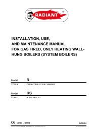
3.2. Layout<br />
<strong>HR</strong> MODEL<br />
14<br />
13<br />
12<br />
11<br />
10<br />
9<br />
8<br />
7<br />
6<br />
5<br />
4<br />
3<br />
2<br />
1<br />
pic. 5<br />
15<br />
16<br />
17<br />
18<br />
19<br />
20<br />
20<br />
21<br />
22<br />
23<br />
24<br />
25<br />
1. Condensate drain<br />
2. Modulating gas valve<br />
3. CH temperatura probe<br />
4. Burner nozzles<br />
5. Flame detection electrode<br />
6. Safety thermostat<br />
7. Heat exchanger<br />
8. Sealed combustion chamber<br />
9. Flue gas extraction fan<br />
10. Flue gas pressure test point<br />
11. Flue gas pressure safety switch<br />
12. Flue gas pressure micro switch<br />
13. Condensate detection probe<br />
14. Safety thermostat<br />
15. Air intake/flue gas pipe<br />
16. Flue gas recoverer<br />
17. Flue gas pressure test point<br />
18. Expansion vessel filling tap<br />
19. Expansion vessel<br />
20. Ignition electrode<br />
21. Air purging device<br />
22. Pump<br />
23. Water pressure switch<br />
24. 3-bar safety valve<br />
25. Unloading tap<br />
<strong>HC</strong> MODEL<br />
17<br />
16<br />
15<br />
14<br />
13<br />
12<br />
11<br />
10<br />
9<br />
8<br />
7<br />
6<br />
5<br />
4<br />
3<br />
31<br />
2<br />
1<br />
30<br />
pic. 6<br />
G<br />
S<br />
18<br />
19<br />
20<br />
21<br />
22<br />
22<br />
23<br />
24<br />
25<br />
32<br />
26<br />
27<br />
28<br />
29<br />
1. Condensate drain<br />
2. DHW temperature probe<br />
3. Modulating gas valve<br />
4. CH temperature probe<br />
5. Burner nozzles<br />
6. Burner<br />
7. Flame detection electrode<br />
8. Safety thermostat<br />
9. Heat exchanger<br />
10. Sealed combustion chamber<br />
11. Flue gas extraction fan<br />
12. Flue gas pressure test point<br />
13. Flue gas pressure safety switch<br />
14. Flue gas pressure micro switch<br />
15. Condensate detection probe<br />
16. Flue gas recoverer<br />
17. Safety thermostat<br />
18. Air intake/flue gas intake<br />
19. Flue gas pressure test point<br />
20. Expansion vessel filling tap<br />
21. Expansion vessel<br />
22. Ignition electrode<br />
23. Air purging device<br />
24. Pump<br />
25. Water pressure switch<br />
26. Safety valve<br />
27. DHW flow limiting device (max 10 litre/minute)<br />
28. Flow switch<br />
29. Mains water inlet filter<br />
30. Adjustable by-pass<br />
31. Three way valve<br />
32. Secondary plate heat exchanger<br />
15
3.3. Operating data<br />
Burner pressures must be verified after a three minute boiler operation time.<br />
<strong>HC</strong> 24 / <strong>HR</strong> 24<br />
Function<br />
Heat<br />
input<br />
[kW]<br />
Heat<br />
output<br />
80-60°C<br />
[kW]<br />
Heat<br />
output<br />
50-30°C<br />
[kW]<br />
Mains gas<br />
pressure<br />
[mbar]<br />
Nozzle diameter<br />
[mm]<br />
Burner pressure<br />
[mbar]<br />
min max min max min max min max<br />
Methane gas G20 11.5 25.5 10.7 24.4 11.4 26.4 20 1.25 2.90 13.2<br />
Butane gas G30 11.5 25.5 10.7 24.4 11.4 26.4 28-30 0.77 5.74 27.7<br />
Propane gas G31 11.5 25.5 10.7 24.4 11.4 26.4 37 0,77 6,5 29,5<br />
Table 3 - Calibration data for <strong>HC</strong> 24 and <strong>HR</strong> 24<br />
Hot water supply ΔT 45°C = 7.8 l/min<br />
Hot water supply ΔT 40°C = 8.7 l/min<br />
Hot water supply ΔT 35°C = 10.0 l/min<br />
Hot water supply ΔT 30°C = 11.7 l/min *<br />
Hot water supply ΔT 25°C = 14.0 l/min *<br />
*Note: mixed water to the tap<br />
<strong>HC</strong> 32 / <strong>HR</strong> 32<br />
Function<br />
Heat<br />
input<br />
[kW]<br />
Heat<br />
output<br />
80-60°C<br />
[kW]<br />
Heat<br />
output<br />
50-30°C<br />
[kW]<br />
Mains gas<br />
pressure<br />
[mbar]<br />
Nozzle diameter<br />
[mm]<br />
Burner pressure<br />
[mbar]<br />
min max min max min max min max<br />
Methane gas G20 12.0 31.5 11.2 30.3 12.0 32.7 20 1.25 2.90 13.2<br />
Butane gas G30 12.0 31.5 11.2 30.3 12.0 32.7 28-30 0.76 4.7 29.0<br />
Propane gas G31 12.0 31.5 11.2 30.3 12.0 32.7 37 0,76 6,5 29,5<br />
Table 4 - Calibration data for <strong>HC</strong> 32 and <strong>HR</strong> 32<br />
Hot water supply ΔT 45°C = 9.6 l/min<br />
Hot water supply ΔT 40°C = 10.9 l/min<br />
Hot water supply ΔT 35°C = 12.4 l/min<br />
Hot water supply ΔT 30°C = 14.5 l/min *<br />
Hot water supply ΔT 25°C = 17.4 l/min *<br />
*Note: mixed water to the tap<br />
3.4. General characteristics<br />
<strong>HC</strong> 24 <strong>HR</strong> 24 <strong>HC</strong> 32 <strong>HR</strong> 32<br />
Category - II2H3+ II2H3+ II2H3+ II2H3+<br />
Burner nozzles no. 12 12 15 15<br />
Minimum CH flow rate l/h 500 500 500 500<br />
Minimum CH pressure bar 0.5 0.5 0.5 0.5<br />
Maximum CH pressure bar 3 3 3 3<br />
Minimum DHW pressure bar 0.5 - 0.5 -<br />
Maximum DHW pressure bar 8 - 8 -<br />
DHW specific capacity ( Δt 30°C) l/min 11.8 - 15.0 -<br />
Electrical power supply - voltage / frequency V ~ Hz 230 ~ 50 230 ~ 50 230 ~ 50 230 ~ 50<br />
Power mains supply fuse A 2 2 2 2<br />
Maximum power consumption W 142 142 177 177<br />
Net weight kg 43.3 41.0 44.5 41.9<br />
Natural gas consumption(*) m 3 /h 2.698 2.698 3.333 3.333<br />
Butane gas consumption Kg/h 2.008 2.008 2.480 2.480<br />
Propane gas consumption Kg/h 1.977 1.977 2.442 2.442<br />
Maximum CH working temperature °C 78+5 78+5 78+5 78+5<br />
Maximum DHW working temperature °C 57+5 57+5 57+5 57+5<br />
Total capacity of expansion vessel l 8 8 8 8<br />
Maximum recommended CH system capacity l 100 100 100 100<br />
Table 5 - General data for each model<br />
(*) Value referred to 15 °C - 1013 mbar<br />
16
<strong>HC</strong> 24 / <strong>HR</strong> 24 Max. heat output Min. heat output 30% heat output<br />
Boiler casing heat loss with burner on % 1.71 2.06 -<br />
Flue system heat loss with burner on % 2.39 4.74 -<br />
Flue system mass capacity g/s 13.5 14.3 -<br />
Flue temp. – air temp. °C 47.9 45.4 -<br />
CO 2<br />
(gas G20) % 7.5 3.0 -<br />
CO 2<br />
(gas G30) % 9.1 3.6 -<br />
Boiler efficiency rate (80-60 °C) (Net) % 95.8 93.2 -<br />
Boiler efficiency rate (50-30 °C) (Net) % 103.4 99.4 -<br />
Boiler efficiency at 30 % of the load (Net) % - - 100.9<br />
Efficiency rating (according to 92/42/CE) -<br />
SEDBUK classification <strong>HC</strong> 24 kW - B (86.5 %)<br />
SEDBUK classification <strong>HR</strong> 24 kW - B (86.6 %)<br />
NOx emission class - 3<br />
Table 6 - <strong>HC</strong> 24 - <strong>HR</strong> 24 model combustion rates<br />
<strong>HC</strong> 32 / <strong>HR</strong> 32 Max. heat output Min. heat output 30% heat output<br />
Boiler casing heat loss with burner on % 1.31 0.66 -<br />
Flue system heat loss with burner on % 2.59 5.94 -<br />
Flue system mass capacity g/s 16.7 16.7 -<br />
Flue temp. – air temp. °C 54.9 50.6 -<br />
CO 2<br />
(gas G20) % 7.6 2.6 -<br />
CO 2<br />
(gas G30) % 9.0 3.0 -<br />
Boiler efficiency rate (80-60 °C) (Net) % 96.1 93.4 -<br />
Boiler efficiency rate (50-30 °C) (Net) % 103.8 99.8 -<br />
Boiler efficiency at 30 % of the load (Net) % - - 100.0<br />
Efficiency rating (according to 92/42/CE) -<br />
SEDBUK classification <strong>HC</strong> 32 kW - B (86.2 %)<br />
SEDBUK classification <strong>HR</strong> 32 kW - B (86.3 %)<br />
NOx emission class - 3<br />
Table 7 - <strong>HC</strong> 32 - <strong>HR</strong> 32 model combustion rates<br />
4. Instructions for the fitter<br />
This is an II2H3+ category boiler and must be installed in compliance with laws and standards enforced in the country of installation,<br />
which are here considered as entirely transcribed.<br />
4.1. Reference standard<br />
In GB, the installation must be carried out by a CORGI Registered Installer. To check for authorised qualified engineers please contact<br />
CORGI 01256-372400. It must be carried out in accordance with the relevant requirements of the:<br />
- Gas Safety Regulations;<br />
- The appropriate Building Regulations either The Building Regulation, The Building Regulations (Scotland), Building Regulations<br />
(Northern Ireland);<br />
- The Water Fittings Regulations or Water Bylaws in Scotland;<br />
- The current I.E.E. Wiring Regulations.<br />
Where no specific instructions are given, reference should be made to the relevant British Standards Code of Practice.<br />
The following list is the full lists of codes of practice and British Standards that engineers should work to in the UK.<br />
It is law in the UK that a competent person installs all gas-burning appliances. Please ensure that the installer is a class of person approved<br />
for the time being by the Heath and Safety Executive for the purpose of carrying out this work. An approved engineer should be<br />
registered to an approved scheme i.e. CORGI 01256-372400.<br />
In GB, the following Codes of Practice apply:<br />
BS 5440: Part 1 2000 - Flues<br />
BS 5440: Part 2 2000 - Air Supply<br />
BS 5446: Installation of hot water supplies for domestic purposes (1 st , 2 nd and 3 rd family gases)<br />
BS 5449: 1990 Forced circulation hot water systems<br />
BS 6700: 1987 - Installation of cold water supplies for domestic purposes (1 st , 2 nd and 3 rd family gases)<br />
BS 6798: 2000 Specification for installation of gas-fired boilers of rated input not exceeding 70 kW net<br />
BS 6891: Specification for installation of low pressure gas pipe work of up to 28 mm (R!) in domestic premises (2nd family gas)<br />
BS 7074: Expansion Vessels and ancillary equipment for sealed water systems<br />
BS 7593: 1992 Code of practice for treatment of water in domestic hot water central heating systems<br />
BS 7671: 2001 IEE wiring regulations.<br />
17
This appliance meets the requirements of:<br />
- UNI EN 677 for GAS-FIRED CENTRAL HEATING BOILERS. SPECIFIC REQUIREMENTS FOR CONDENSING BOILERS WITH<br />
NOMINAL HEAT INPUT ≤ 70 kW,<br />
- IPX4D rating for electrical appliances,<br />
- EMC DIRECTIVE 89/336 CE,<br />
- LVD DIRECTIVE 2006/95 CE,<br />
- BOILER EFFICIENCY DIRECTIVE 92/42 CE<br />
Failure to install a gas appliance correctly and in accordance with the above norms could lead to prosecution. It is in the interest of the<br />
installer and safety that the law is complied with.<br />
The manufacturers instructions form an integral part of the installation and should be left with the appliance but do not over ride in anyway<br />
statutory obligations.<br />
4.2. System details<br />
4.2.1. Central heating circuit<br />
The boiler is designed for use in a sealed central heating system in accordance with the requirements of BS 5449 and BS 6798. The<br />
system should be designed to operate with flow temperatures of up to 78 °C. When designing the system, the pump head, expansion<br />
vessel size, mean radiator temperature, ect. must all be taken into account. Refer to the pump performance table for guidelines.<br />
System volume: the expansion vessel incorporated into the boiler is suitable for a sealed heating system. The boiler is supplied with the<br />
following components built in:<br />
Pressure relief valve: set to operate at 3 bars. The outlet connection of the boiler safety valve must terminate to atmosphere in accordance<br />
with current regulations. The manufacturer will not be held responsible for flooding caused by the operation of the safety valve in<br />
the case of system overpressure.<br />
Pressure gauge: to indicates the system pressure to be maintained.<br />
Expansion vessel: capacity of 8 litres.<br />
By-pass: The boiler incorporates an automatic by-pass.<br />
All recirculatory water systems will be subject to corrosion unless an appropriate water treatment is applied. This means that the efficiency<br />
of the system will deteriorate as corrosion sludge accumulates within the system, risking damage to pump and valves, boiler<br />
noise and circulation problems.<br />
All systems must be thoroughly drained and flushed out. System additives - corrosion inhibitors and flushing agents/descalers should<br />
comply to BS7593 requirements. It is important to check the inhibitor concentration after installation, system modification and at every<br />
service in accordance with the manufacturer’s instructions.<br />
4.2.2. Filling the central heating system<br />
The system design pressure (cold) should be set to 1,5 bar. This pressure is equivalent to a static head of 15,4 metres of water. Provision<br />
should be made to replace water lost from the system. This can be by manual or automatic means as shown in Pics. 7 and 8. A double<br />
check valve assembly must be used as show in pic 8.<br />
Filling of the system must be carried out in a manner approved by the local Water Undertaking. Where allowed the system may be filled<br />
via a temporary connection as shown in pic 7. After filling, always disconnect the flexible hose of the filling loop. All fittings used in the<br />
system must be able to withstand pressures up to 3 bar. Drain taps must be used to allow the system to be completely drained.<br />
In order to prevent scaling or deposits in the primary heat exchanger, the mains supply water to the<br />
heating circuit must be treated according to the requirements of standard.<br />
This treatment is indispensable in the case where the circuit is frequently topped-up or when the system is<br />
often either partially or fully drained.<br />
18<br />
CH return<br />
Hose unions<br />
Temporary hose<br />
(disconnect after filling)<br />
Mains water<br />
supply<br />
Additional<br />
stop valve<br />
Double check valve<br />
assembly<br />
(note direction of flow)<br />
Heating<br />
circuit<br />
return<br />
pic. 7 pic. 8<br />
Double<br />
check valve<br />
assembly<br />
Test<br />
cock<br />
Overflow<br />
Stop<br />
valve<br />
Mains<br />
water<br />
supply<br />
Feed cistern to be<br />
located above<br />
highest point in<br />
the system
4.2.3. Domestic Hot Water Circuit<br />
All DHW circuits, connections, fittings, etc. should be fully in accordance with relevant standards and water supply regulations.<br />
Your attention is drawn for GB: Guidance G17 to G24 and recommendation R17 to R24 of the Water Regulations Guide.<br />
4.3. Site requirements<br />
4.3.1. Choosing where to install the boiler<br />
The following must be taken into account when choosing where to install the boiler:<br />
- Approved document L1 + L2 government guidelines.<br />
- Check the wall is strong enough to support the weight of the boiler.<br />
- Do not fit the boiler above any equipment that may affect operation (kitchen appliances that emit steam or greasy vapour, washing<br />
machines, etc.).<br />
- Do not install natural draught boilers in corrosive or very dusty atmosphere areas, such as hairdressing salons or laundries as this<br />
would greatly reduce the boiler’s lifespan.<br />
4.3.2. Positioning the boiler<br />
Each boiler is supplied with a paper template (pic. 10), within its packaging,<br />
allowing arrangement of CH pipe system, DHW pipe system, gas supply pipe<br />
system and air intake/flue gas discharge system before actually installing the<br />
boiler.<br />
The template is made of heavy-duty paper, it is to be affixed to the wall where<br />
the boiler is to be mounted using a carpenter’s level.<br />
It provides all the indications required to drill the boiler fixing holes to the wall,<br />
procedure which is done using two screws and wall plugs.<br />
The lower area of the template displays where to mark the exact point at which<br />
the couplings are to be positioned for boiler connection to the gas supply pipe,<br />
water mains supply pipe, DHW flow pipe, CH flow and return pipes.<br />
The upper area of the template displays where air intake and flue gas ducts are<br />
to be positioned.<br />
The manufacturer recommends leaving a space all round the boiler during<br />
installation as follows:<br />
- at least 2,5 cm on the right and left;<br />
- at least 25 cm above and below.<br />
This facilitates service operations on the boiler, e.g. maintenance and repair<br />
interventions (pic. 9).<br />
2,5 cm<br />
25 cm<br />
2,5 cm<br />
2,5 cm<br />
pic. 9<br />
25 cm<br />
Since the temperature of the walls on which the boiler is mounted and external temperature of coaxial air/flue gas<br />
system do not exceed 60 °C, no minimum distance from flammable walls is to be accounted for.<br />
Boilers with split pipe flue system: in presence of flammable walls and flue gas ducts through such walls, ensure air gap<br />
of 15 mm between wall and flue gas ducts.<br />
19
DHW<br />
CWI<br />
R<br />
F<br />
G<br />
S<br />
Domestic hot water<br />
Cold water inlet<br />
CH system return<br />
Gas<br />
Condensate drain<br />
S<br />
G F DHW CWI R<br />
20<br />
pic. 10
4.3.3. Boiler room ventilation<br />
The boiler has sealed combustion chamber. Combustion air is not drawn from boiler room therefore specific recommendations need not<br />
to be applied concerning the boiler room or openings and ventilation provided to the boiler room.<br />
It is mandatory to install the boiler in an adequate room following laws and standards applicable in the country of<br />
installation, which are considered as fully transcribed in this manual.<br />
4.3.4. Flue<br />
The following guidelines indicate the general requirements for siting balanced flue terminals. For GB recommendations are given in<br />
BS 5440 Part 1. If the terminal discharges onto a pathway or passageway, check that combustion products will not cause a nuisance<br />
and that the terminal will not obstruct the passageway. If a terminal is less than 2 metres above a balcony, above ground or above a flat<br />
roof to which people have access, then a suitable terminal guard must be provided.<br />
TERMINAL POSITION WITH MINIMUM DISTANCE (mm)<br />
Aa Directly below an opening, air brick, opening windows, etc. 300<br />
Ba Above an opening, air brick, opening window etc. 300<br />
Ca Horizontally to an opening, air brick, opening window etc. 300<br />
D Below gutters, soil pipes or drain pipes 25<br />
E Below eaves. 25<br />
F Below balconies or car port roof. 25<br />
G From a vertical drain pipe or soil pipe. 25<br />
H From an internal or external corner. 25<br />
I Above ground, roof or balcony level. 300<br />
J From a surface or boundary line facing a terminal. 600<br />
K From a terminal facing a terminal (Horizontal flue). 1200<br />
From a terminal facing a terminal (Vertical flue). 600<br />
L From an opening in carport (e.g. door, window) into the dwelling. 1200<br />
M Vertically from a terminal on the same wall. 1500<br />
N Horizontally from a terminal on the same wall. 300<br />
R From adjacent wall to flue (vertical only). 300<br />
S From an adjacent opening window (vertical only). 1000<br />
T Adjacent to windows or openings on pitched and flat roofs 600<br />
U Below windows or openings on pitched roofs 2000<br />
a In addition, the terminal should be no nearer than 150 mm to an<br />
opening in the building fabric formed for the purpose of accommodating<br />
a built-in element such as a window frame. See BS 5440 Pt. 1.<br />
J,K<br />
T<br />
U<br />
R<br />
M<br />
N<br />
C<br />
D<br />
E<br />
A<br />
I<br />
I<br />
I<br />
S<br />
I<br />
F<br />
L<br />
G<br />
I<br />
B<br />
A<br />
H<br />
A F J,K<br />
H<br />
pic. 11<br />
Likely flue positions requiring<br />
a flue terminal guard<br />
21
4.4. Installation (authorised personnel)<br />
Accessories and spare parts for installation and service procedures are to be supplied by the<br />
Manufacturer. Should non original accessories and spare parts be employed, boiler proper performance is<br />
not guaranteed.<br />
4.4.1. Packaging<br />
Boiler is shipped in a sturdy cardboard box. Remove boiler from cardboard box and check its integrity.<br />
The packing materials can be recycled and should be disposed of at an appropriate waste collection site. Keep packaging out of reach<br />
of children, as it may be dangerous.<br />
The manufacturer shall not be held responsible for harm to people and/or animals, and/or damage to property due to failure in following<br />
the above mentioned instructions.<br />
Packaging includes:<br />
- copper pipe kit for boiler connection to the gas mains, to the CH system (<strong>HC</strong> and<br />
<strong>HR</strong>) and DHW system (<strong>HC</strong>) (pic.12);<br />
- four shutoff valves: one for gas, one for heating flow, one for heating return and one<br />
for cold water supply (pic.12);<br />
- a bag containing:<br />
a) boiler installation, use and maintenance manual;<br />
b) boiler wall mounting template (pic. 10);<br />
c) metal plate for fixing the boiler to the wall;<br />
d) two screws and wall plugs for fixing the metal plate to the wall;<br />
e) one closing caps with gaskets.<br />
f) benchmark commissioning booklet.<br />
g) air intake diaphragm.<br />
pic.12<br />
4.4.2. Installing the boiler<br />
Before connecting the boiler to the CH and DHW systems, clean the pipes carefully. Prior to operating a NEW system,<br />
eliminate any metallic leftover during manufacturing and welding process, and any oil or grease deposits, which might<br />
get into the boiler and damage it or affect operation. Prior to operating an UPGRADED system (addition of radiators,<br />
boiler replacement, etc.), clean it thoroughly to remove all sludge and foreign particles. Clean the system using a<br />
non-acid product available on the market. Do not use solvents as they could damage the components of the system. In<br />
the (new or upgraded) central heating system, it is always advisable to add to the water, in a suitable concentration, a<br />
corrosion inhibiting product for use in multi-metal systems to produce a protective film on internal metal surfaces. The<br />
Manufacturer can not be held liable for injury to people or animals or damage to property resulting from failure to follow<br />
the above instructions.<br />
Proceed as follows to install the boiler:<br />
• Fix the template (pic. 10) onto the wall.<br />
• Drill two 12 mm Ø holes in the wall to accommodate the boiler bracket wall plugs.<br />
• Arrange air intake/flue gas system in the wall as needed.<br />
• Secure the boiler bracket to the wall using the wall plugs supplied.<br />
• Position the gas supply fitting (G), the mains water fitting (F), the DHW flow fitting (C, only in model <strong>HC</strong>), the CH flow fitting (M) and the<br />
CH return fitting (R) as shown on the template (refer to the lower part).<br />
• Provide a disposal system for relieving the 3-bar safety valve.<br />
• Hang the boiler on the bracket fixed onto the wall.<br />
• Connect the boiler to the mains pipes using the kit supplied with the boiler (refer to subsections 4.4.3. and 4.4.4.).<br />
• Connect the boiler to the air intake and flue gas exhaust system (refer to subsections 4.5.1; 4.5.2; 4.5.3 and 4.5.4).<br />
• Connect the power supply, room thermostat (optional) and other accessories (refer to subsections 4.5.5; 4.5.6 and 4.5.7).<br />
4.4.3. Gas main connection<br />
The gas installation should be in accordance with the relevant standards. In GB this is BS 6891.<br />
Gas supply pipe cross-section must be equal or greater than boiler gas pipe.<br />
Cross-section gas pipe size calculation depends on its length, layout pattern, gas flow rate. Gas pipe size is to be dimensioned<br />
accordingly.<br />
22<br />
Comply with installation standards BS 6891 enforced in the installation country which are considered as fully<br />
transcribed in this booklet.<br />
Remember that before operating an indoor gas distribution system and before connecting it to a meter, it must be<br />
checked for leaks.<br />
Adhere to the following leak test instructions:<br />
- leak test is to be carried out before pipes are covered;<br />
- leak test is not to be carried out employing flammable gas: use air or nitrogen for this purpose;<br />
- when gas is already in the pipes supplying the boiler, leak testing by naked flame is forbidden, use specific<br />
products available on the market.
To prevent the main exchanger pipes from getting clogged with any material accumulated in the system it is<br />
necessary to install a filter which can be inspected (Y-shaped type) with Ø 0.4mm-mesh span, on the heating return<br />
pipe, before the boiler (part of hydraulic kit) like our accessory 0KITFILT00 (pic.13)<br />
pic. 13<br />
When connecting the boiler to gas supply network, install an appropriately sized and made gasket (pic. 14).<br />
The boiler gas inlet thread configuration is not appropriate for hemp, plastic tape or similarly made gaskets.<br />
Gasket<br />
pic.14<br />
4.4.4. Hydraulic connections<br />
Prior to installing the boiler, the hydraulic system is to be cleaned in order to remove impurities; they could be present in system components<br />
and damage the pump and the heat exchanger (refer to 4.4.2 paragraph).<br />
CENTRAL HEATING<br />
CH flow and CH return pipes must be connected to the relevant 3/4” F and R couplings on the boiler (pic. 4).<br />
When calculating the cross section of CH system pipes, bear in mind load losses induced by radiators, thermostatic valves, radiator gate<br />
valves, and the configuration of the system itself.<br />
76<br />
It is advisable to convey the discharge flow of boiler safety valve to the sewer system. Should the above precaution<br />
not be implemented and the safety valve be activated, boiler room flooding may occur.<br />
Manufacturer shall not be held responsible for any damage resulting as failure in observing the above mentioned<br />
technical precaution.<br />
DOMESTIC HOT WATER (only for <strong>HC</strong> model)<br />
DHW flow and water mains inlet pipes are to be connected to the relevant 1/2” CWI and DHW couplings on the boiler (pic. 4).<br />
Hardness of water supplied to the boiler may increase the plate heat exchanger cleaning/replacement frequency.<br />
All DHW circuits, connections, fittings, etc. should be fully in accordance with relevant standards and water supply regulations.<br />
Depending on hardness level of the water supplied, it might be necessary installing a suitable water treatment device<br />
for domestic use and in compliance with applicable laws and standards.<br />
Water treatment is always advisable when water supplied to the boiler is more than 20°F hard.<br />
Water treated by commonly marketed water softeners, due to PH level induced in water, may not be compatible with<br />
some components in system.<br />
CONDENSATE DRAIN<br />
Comply with condensate drain laws and standards applicable in the country of installation and which are considered herein integrally<br />
transcribed.<br />
When the law is not stating differently, the condensate produced by combustion, is to be routed (via the condensate drain S in pic. 4)<br />
through a discharge system connected to the domestic sewer, which due to its basicity, counteracts flue gas condensate acidity.<br />
In order to avoid domestic sewer odour to reach the premises, it is advisable to install an appropriate device between the discharge<br />
system and the domestic sewer.<br />
The condensate drain system and the domestic discharge system is to be made of adequate condensate resistant material.<br />
Manufacturer shall not be held responsible for any damage to people, animals or objects, resulting as failure in observing the above<br />
mentioned technical precaution.<br />
23
Boiler<br />
Termination to an internal soil and<br />
vent pipe<br />
Boiler<br />
External termination via internal discharge<br />
branch<br />
e.g. sink waste - downstream<br />
50 mm per metre of pipe run<br />
2,5° Minimum fall<br />
Sink<br />
50 mm per metre of pipe run<br />
2,5° Minimum fall<br />
Pipe must terminate<br />
above water level but<br />
below surrounding<br />
surface<br />
450 mm min<br />
Boiler<br />
Termination to a drain or gully<br />
Pipe must terminate above<br />
water level but below<br />
surrounding surface<br />
Boiler<br />
Termination to a purpose made soakaway<br />
500 mm min<br />
50 mm per metre of pipe run<br />
2,5° Minimum fall<br />
50 mm per metre of pipe run<br />
2,5° Minimum fall<br />
Holes in the soak-away<br />
must face away from the<br />
building<br />
FAILURE TO INSTALL THE CONDENSATE DISCHARGE PIPEWORK CORRECTLY WILL AFFECT THE RELIABLE<br />
OPERATION OF THE BOILER<br />
The condensate discharge pipe MUST NOT RISE at any point along its length. There MUST be a fall of AT LEAST 2.5° (50mm per metre)<br />
along the entire run.<br />
1. The condensate outlet will accept 21.5 mm (3/4 in) plastic overflow pipe which should generally discharge internally into the house<br />
hold drainage system. If this is not possible, discharge into an outside drain is acceptable.<br />
2. Ensure the discharge of condensate complies with any national or local regulations in force.<br />
BS 6798:2000 & Part H1 of the Building Regulations give further guidance.<br />
3. The discharge pipe should be run in a proprietary drain pipe material e.g. PVC, PVC-U, ABS, PVC-C or PP.<br />
4. Metal pipework is NOT suitable for use in condensate discharge systems.<br />
5. The pipe should be a minimum of 21.5 mm diameter and must be supported using suitably spaced clips to prevent sagging.<br />
6. It is advisable to keep the condensate pipe internal.<br />
7. External runs greater than 3 metres or runs in cold areas should use 32 mm waste pipe.<br />
8. If the boiler is fitted in an unheated location the entire condensate discharge pipe should be treated as an external run.<br />
9. In all cases discharge pipe must be installed to aid disposal of the condensate. To reduce the risk of condensate being trapped, as<br />
few bends and fittings as possible should be used.<br />
10. When discharging condensate into a soil stack or waste pipe the effects of existing plumbing must be considered. If soil<br />
pipes or waste pipes are subjected to internal pressure fluctuations when WC’s are flushed or sinks emptied then back-pressure may<br />
force water out of the boiler trap and cause appliance lockout.<br />
Examples are shown of the following methods of termination:<br />
i) to an internal soil & vent pipe<br />
ii) via an internal discharge branch (e.g. sink waste)<br />
iii) to a drain or gully<br />
iv) to a purpose made soakaway<br />
24
4.4.5. Adjustable by-pass<br />
The boiler is equipped by an adjustable by-pass. By-pass operation can be inhibited.<br />
Pic. 15A shows an adjusting by-pass screw set for by-pass operation preclusion.<br />
Pic. 15B shows an adjusting by-pass screw set for by-pass operation.<br />
The boiler is supplied with by-pass set to closed by-pass.<br />
Closed<br />
By-pass<br />
Open<br />
By-pass<br />
pic.15 A<br />
pic.15 B<br />
4.5. Flue options<br />
4.5.1. Air intake / flue gas discharge system<br />
As far as flue gas discharge into the atmosphere and air intake / flue gas discharge systems are concerned, comply with laws enforced<br />
in the country of installation, which are considered as fully transcribed in this manual.<br />
In accordance with BS 5440 Part 1 and BS 5440 Part 2 the boiler is equipped with safety devices checking correct flue<br />
gas exhaustion. Should an air/flue gas system malfunction occur, the safety devices shut down the boiler and flashing<br />
red light 4.<br />
It is strictly forbidden to tamper with and/or prevent operation of such safety devices.<br />
Should the boiler repeatedly shut down, it is necessary to have air/flue gas system ducts inspected, as they might be<br />
obstructed or inadequate to flue gas discharge into the atmosphere.<br />
In air intake/flue gas discharge systems, specific, manufacturer approved, condensate acid-resistant systems for<br />
condensing boiler are to be used.<br />
Flue gas discharge pipes are to be installed tilted toward the boiler so that condensate runs in the direction of the<br />
combustion chamber, which is designed for condensate collection and drainage.<br />
Should the above procedure not be possible to be implemented, it is necessary to install, in condensate stagnation<br />
areas, devices designed for condensate collection and conveying to the condensate drain system.<br />
It is necessary to avoid formation of condensate stagnation areas in the flue gas discharge system, with the exception<br />
of the condensate drain siphon eventually connected to the discharge system itself.<br />
The manufacture shall not be held liable for damage resulting in incorrect installation, use, modification of the equipment or non-observance<br />
of instructions provided by the manufacturer or applicable installation standards involving the product.<br />
pic. 16<br />
LEGENDA<br />
A Air intake - S Flue gas discharge - Condensate - Rain<br />
25
Type<br />
B22<br />
Type<br />
C12<br />
4.5.2. Configuration of air/flue system pipes<br />
Types: B22, C12, C32, C42, C52, C82<br />
Type<br />
C32<br />
B22<br />
This boiler is intended for connection to an<br />
existing flue system either inside or outside the boiler<br />
room. Combustion air is drawn straight from the boiler<br />
room itself and flue gas is conveyed to the outside. The<br />
boiler must not be fitted with an anti-wind gust system;<br />
it must be equipped with a fan mounted after the<br />
combustion chamber.<br />
C12<br />
This boiler is intended for connection to horizontal flue<br />
gas and air-intake pipes connected<br />
to the outside by means of coaxial or split pipes. The<br />
distance between the air intake pipe and the flue gas<br />
pipe must be at least 250 mm and both terminals must<br />
be positioned in a 500mm-side square area.<br />
Type<br />
C42<br />
C32<br />
This boiler is intended for connection to vertical flue gas<br />
and air-intake pipes connected to the outside by means<br />
of coaxial or split pipes. The distance between the air<br />
intake pipe and the flue gas pipe must be at least 250<br />
mm and both terminals must be positioned in a<br />
500mm-side square area.<br />
C42<br />
This boiler is intended for connection to a common<br />
chimney pipe system that includes two pipes, one for<br />
the air intake and the other for flue gas discharge. These<br />
pipes may be coaxial or split. The flue gas chimney<br />
system must comply with current standards.<br />
Type<br />
C52<br />
C52<br />
Boiler with separate pipes for air intake and flue gas. Air<br />
and flue gas may have different discharge pressures. Air<br />
and flue gas terminals must not face each other from<br />
opposite walls.<br />
C82<br />
This boiler is intended to be connected to a combustion<br />
air-intake terminal and to a single flue gas<br />
terminal or to a common chimney.<br />
The flue gas chimney system must comply with current<br />
standards.<br />
Type<br />
C82<br />
26
In order to ensure that the appliance functions correctly and efficiently, the flue connection between the boiler and the<br />
flue terminal must be made using original components specifically designed for condensing boilers.<br />
Traditional flue components cannot be used for conveying exhaust fumes from condensing boilers, nor vice versa.<br />
It is recommended that:<br />
- for the exhaust discharge duct, the entire length of the flue slopes upwards towards the exterior in order to facilitate the flow of<br />
condensate back to the combustion chamber, which has been specifically designed to collect and drain the acidic condensate;<br />
- for the air intake, the entire length of the duct slopes upwards towards the boiler to prevent the entry of rainwater, dust or foreign<br />
bodies into the pipe;<br />
in the case where a horizontal coaxial system is installed, the coaxial terminal must be positioned horizontally in that the exhaust duct<br />
has been specifically designed with the required slope (Ø 60) and the air intake (Ø 100) has been suitably protected against the weather.<br />
4.5.3. Ø 100/60 mm air/flue gas coaxial duct system<br />
Type C12<br />
The minimum permissible length of horizontal coaxial pipes is 0.5 metre, not including the first elbow connected to the boiler.<br />
The maximum permissible length of horizontal coaxial pipes is 5 metres for <strong>HC</strong>-<strong>HR</strong> 24 and 4 metres for <strong>HC</strong>-<strong>HR</strong> 32, not including the first<br />
elbow connected to the boiler. For each additional elbow, the maximum permissible length must be reduced by 1 metre.<br />
In addition, the pipe must have a 1% slope to prevent rainwater entering it.<br />
Choosing the applicable diaphragm supplied with the boiler (pic. 17)<br />
<strong>HR</strong> 24 and <strong>HC</strong> 24 <strong>HC</strong> 32 and <strong>HC</strong> 32<br />
Pipe length (m)<br />
Air intake diaphragm<br />
(mm)<br />
0,5≤ L ≤ 2 80<br />
2 ≤ L ≤ 5 82<br />
* excluding the first elbow connected to the boiler<br />
Pipe length (m) Air intake diaphragm<br />
(mm)<br />
0,5≤ L ≤ 2 87<br />
2 ≤ L ≤ 4 -<br />
* excluding the first elbow connected to the boiler<br />
0CONDASP01<br />
FROM 0,5 M TO 5 M<br />
AIR INTAKE DIAP<strong>HR</strong>AGM<br />
SEALING<br />
CAP<br />
NEOPRENE<br />
GASKET<br />
Supplied with the boiler<br />
NEOPRENE<br />
GASKET<br />
pic.17<br />
Type C32<br />
The minimum permissible length of vertical coaxial pipes is 0,5 metre, equal to the length of the chimney.<br />
The maximum permissible length of vertical coaxial pipes is 5 metres for <strong>HC</strong>-<strong>HR</strong> 24 and 4 metres for <strong>HC</strong>-<strong>HR</strong> 32, including the terminal.<br />
For each additional elbow, the maximum permissible length must be reduced by 1 metre.<br />
Choosing the applicable diaphragm supplied with the boiler (pic. 17)<br />
27
<strong>HR</strong> 24 and <strong>HC</strong> 24 <strong>HC</strong> 32 and <strong>HR</strong> 32<br />
Pipe length (m)<br />
Air intake diaphragm<br />
(mm)<br />
0.5≤ L ≤ 2 80<br />
2 ≤ L ≤ 5 82<br />
Pipe length (m) Air intake diaphragm<br />
(mm)<br />
0,5≤ L ≤ 2 87<br />
2 ≤ L ≤ 4 -<br />
The boiler is equipped with a device for controlling the emissions of the products of combustion. If the flue gas and/or<br />
combustion air intake system fails, the device sets the equipment in the safety configuration (subsection 2.3.3).<br />
175<br />
750<br />
107<br />
Ø100<br />
pic.18<br />
450<br />
325<br />
These pictures are merely an indication. For installation of optional fittings please refer to the instruction enclosed to the same fittings.<br />
4.5.4. Ø 80 mm air/flue gas split duct system<br />
The below data are referred to air intake/flue gas discharge system, implemented with original, rigid and smooth<br />
ducts, delivered by the manufacturer.<br />
0KITSDOP01<br />
Neoprene<br />
gasket<br />
Diaphragm<br />
Neoprene<br />
gasket<br />
28<br />
pic. 19
750<br />
Installation types C12- C32- C42- C52- C82<br />
<strong>HR</strong>-<strong>HC</strong> 24 and <strong>HR</strong>-<strong>HC</strong> 32<br />
For installations with separate air intake and<br />
flue gas discharge pipes the split base kit (code<br />
0KITSDOP01) must be used. The kit consists of the<br />
following components (pic. 20):<br />
• no. 1 Ø 80 mm female stub pipe with flange for<br />
connection to the flue gas discharge pipe (flue gas<br />
deflector included);<br />
• no. 1 Ø 80 mm female stub pipe with flange for<br />
connection to the air intake pipe;<br />
• no. 1 standard air deflector;<br />
• no. 2 air intake diaphragm (43 and 52 mm);<br />
• fixing screws and seals.<br />
AIR INTAKE<br />
STUB<br />
PIPE<br />
NEOPRENE<br />
GASKET<br />
DIAP<strong>HR</strong>AGM<br />
NEOPRENE<br />
GASKET<br />
AIR<br />
DEFLECTOR<br />
FLUE GAS<br />
DISCHARGE<br />
STUB PIPE<br />
pic.20<br />
Air intake<br />
The minimum length of the air intake pipe is 0.5 metre.<br />
Each wide-radius 90° elbow (R=D) installed on the air intake pipe is equal to 1 m linear length.<br />
Each narrow-radius 90° elbow (R
Configuration of Ø 80 mm flue gas discharge<br />
and air intake pipes<br />
Example no. 1 (pic. 23)<br />
Primary air intake and flue gas discharge through two opposing outside<br />
walls.<br />
Example no. 2 (pic. 24)<br />
Primary air intake through outside wall and flue gas discharge through<br />
outside wall behind the boiler.<br />
Example no. 3 (pic. 25)<br />
Primary air intake through outside wall and flue gas discharge through<br />
the same wall.<br />
Example no. 4 (pic. 26)<br />
Primary air intake through outside wall and flue gas discharge through<br />
the same wall behind the boiler.<br />
Example no. 5 (pic. 27)<br />
Primary air intake through outside wall and flue gas discharge through<br />
the roof.<br />
These pictures are merely an indication.<br />
pic.23<br />
pic.24<br />
pic.25<br />
30<br />
pic.26<br />
pic.27
4.5.5. Electrical supply connection<br />
The boiler is supplied with a three-poled power cable, already connected to the electronic board and it is provided with an anti-rupture<br />
firming clamp.<br />
The boiler is to be connected to a 230V~50Hz electrical power supply.<br />
When connecting the boiler to power mains, follow correct phase/neutral polarity sequence.<br />
Installation standards BS7671 IEE WIRING REGS must be complied with and are which are considered herein integrally transcribed.<br />
An easy accessible two-poled switch is to be installed externally to the boiler, in an easy to reach position. The switch minimum distance<br />
between contacts is to be 3 mm.<br />
The switch is to allow power supply interruption in order to safely perform maintenance and service procedures.<br />
Power supply to the boiler is to be fitted with a differential magnetic-thermal automatic switch of appropriate shut-down capacity.<br />
Electrical power supply is to be appropriately earthed.<br />
The above mentioned safety measure is to be verified. When in doubt, ask a qualified technician to thoroughly check the power network.<br />
DO NOT:<br />
• touch the electrical connections with wet hands<br />
• put any electrical cables under stress<br />
• leave the electrical components exposed to weather conditions<br />
Check and inspect the cable supplied with the boiler do not use if this cable is damaged. The boiler should be<br />
connected in line with the requirements of the IEE electrical regulations and should only be connected by a competent<br />
person.<br />
The manufacturer shall not be held responsible for any damage due to failure in grounding the system: gas, hydraulic,<br />
or CH system pipes are not suitable for grounding power networks.<br />
4.5.6. Room thermostat connection (optional equipment)<br />
The boiler can be connected to a room thermostat (not supplied with the boiler).<br />
Room thermostat contacts must be properly sized for 5 mA at 24 V D.C.<br />
The room thermostat must be connected to the terminal block shown in pic. 39, after removal of the jumper which is delivered as standard<br />
fitting to the boiler.<br />
Room thermostat wiring must not be grouped together with power mains supply cables.<br />
4.5.7. External temperature probe installation (optional equipment) and “sliding temperature” operation<br />
The boiler can be connected to an external temperature probe (optional equipment), which adjusts CH flow temperature for temperature<br />
compensation operation (pic. 28).<br />
The manufacturer supplies 0SONDAES01: external probe for direct connection to the boiler.<br />
pic.28<br />
31
Only original external temperature probes supplied by the manufacturer must be used.<br />
If non-original external temperature probes are used, correct operation of the boiler cannot be guaranteed.<br />
External temperature probe connection is to be performed by means of a double insulated wire, its minimum cross-section is to be 0.35<br />
sq.mm.<br />
External temperature probe is to be connected to M8 position of the boiler printed circuit board (pic. 29).<br />
External temperature probe wiring is NOT to be grouped together with power mains supply cables.<br />
pic.29<br />
External temperature probe is to be installed on an outside wall facing north/north-east, in a position protected from atmospheric agents.<br />
Do not install in window area, next to ventilation openings, or heat sources.<br />
The external temperature probe automatically modifies CH flow temperature in relation to:<br />
- sensed outdoor temperature;<br />
- selected thermoregulation curve;<br />
- selected virtual room temperature.<br />
The thermoregulation curve is selected via trimmer .<br />
It is important for trimmer to be set to a value of 1-3 (pics. 30).<br />
The virtual room temperature is set via adjuster 11 (pic. 1), which, when the external temperature probe is installed, loses its capability to<br />
set CH flow temperature (see subsection 2.2.6.).<br />
1 2<br />
0 3<br />
pic.30<br />
32
100<br />
3<br />
2,5<br />
CH flow temperature (°C)<br />
80<br />
60<br />
40<br />
2<br />
1,5<br />
1,25<br />
1<br />
Thermoregulation curves<br />
coefficient<br />
pic.31<br />
20<br />
20 16 12 8 4 0 -4 -8 -12 -16<br />
External temperature (°C)<br />
4.5.8. Installation of the OpenTherm remote control (optional equipment only for <strong>HR</strong> model)<br />
The boiler can be connected to an OpenTherm remote control, an optional only for <strong>HR</strong> model supplied by the manufacturer.<br />
The remote control must be installed by a suitably qualified person.<br />
Only original remote controls supplied by the manufacturer must be used.<br />
If non-original remote controls are used, correct operation of the boiler cannot be guaranteed.<br />
For installation instructions, refer to the booklet accompanying the remote control.<br />
Precautions to take when installing the remote control:<br />
• The remote control cables must NOT be routed together with power cables: otherwise the disturbance would cause the remote<br />
control to malfunction.<br />
• Position the remote control on a wall inside the building, about 1,5 metres from the floor, in a suitable position for measuring the environmental<br />
temperature.<br />
• Do not install in alcoves, behind doors or curtains, near sources of heat, or exposed to sunlight, draughts or spray.<br />
4.5.9. Loading the system<br />
Once all boiler connections have been completed, CH system can be filled.<br />
This procedure is to be cautiously carried out, following each below indicated step:<br />
- Open the air purging valves on all radiators and verify the boiler automatic valve operation.<br />
- Gradually open the filling loop to fill the system up, checking that all automatic air purging valves installed in the system properly work.<br />
- Close all radiator air purging valves as soon as water starts coming out.<br />
- Check boiler water pressure gauge for pressure to reach 1-1.3 bars reading.<br />
- Shut the filling loop and bleed any air out again by opening all air purging valves on radiators.<br />
- Start the boiler and, as soon as the system reaches working temperature, stop the boiler and pump and repeat the air purging<br />
procedures.<br />
- Allow the system to cool and restore water pressure to 1-1.3 bars.<br />
WARNING<br />
As far as domestic heating systems treatment of water is concerned, in order to optimize performance and safety, to preserve<br />
these conditions over time, to ensure long-lasting regular operation of auxiliary equipment as well, and to minimize energy<br />
consumption, thereby integrating current local laws and standards it is advisable to use specific products that are suitable for<br />
multi-metal plants.<br />
WARNING<br />
The safety fluid flow meter will not allow the burner to be started when CH water flow is too low. CH system water pressure is<br />
not to be below 1 bar; restore proper value as needed via the filling loop. The procedure is to be carried out while water in the<br />
system is cold.<br />
Boiler pressure gauge displays water pressure in the CH system.<br />
WARNING<br />
After long boiler inactivity, its pump may be stuck. Before operating the boiler, follow the below indicated pump clearing<br />
procedure:<br />
- unscrew the protective bolt, located in the center front section of pump motor;<br />
- put a screwdriver into the opening and manually rotate the circulation unit shaft clockwise;<br />
- once the pump is reliased, screw back on the protection bolt and check for water leaks.<br />
When the pump protective bolt is removed, some water may flow out. Before re-installing the boiler external housing, verify all<br />
internal surfaces to be dry.<br />
33
4.6. Burner adjustment<br />
A) Max power adjustment<br />
• Check the gas supply pressure (refer to tables 3 and 4)<br />
• Remove the plastic cap (С, pic. 32), which is positioned on top on the modulating coil and protects<br />
the gas valve pressure adjusting nut and screw.<br />
• Connect a manometer to V test point in pic. 33.<br />
• Adjust the screw (maxR, pic. 34) to MAX by rotating fully clockwise.<br />
• Select WINTER boiler operation on switch 9 (pic. 1).<br />
• Start the boiler in “chimney sweep” mode (subsection 6.5.1.).<br />
• Turn (external) nut К clockwise to increase nozzle pressure or vice versa (pic. 35).<br />
• In LPG-fuelled boilers, turn the brass nut К fully clockwise.<br />
B) Min power adjustment<br />
• Disconnect the electrical wiring from the modulation coil (М, pic. 33).<br />
• Turn the burner on and check MIN pressure according to tables 3 and 4.<br />
• To adjust the pressure, hold nut К still using a 100 mm tool, and turn screw W clockwise to increase<br />
or counter-clockwise to decrease the gas pressure (pic. 35).<br />
• Re-connect the electrical wiring to the modulation coil.<br />
C) Final settings<br />
• Turn the Pacc screw (pic. 34) to the middle set point, exit “chimney sweep” mode (subsection 6.5.1.)<br />
and make sure the burner works correctly and silently. If necessary, increase or decrease ignition<br />
power via the Pacc adjuster (clockwise to increase, counter-clockwise to decrease).<br />
• Re-check the min and max gas valve pressure values.<br />
• Adjust as necessary.<br />
• Fit on plastic protective cap C.<br />
• Close gas pressure check valves.<br />
• Check for gas leaks.<br />
pic. 32 - Gas valve modulation coil<br />
C<br />
V<br />
M<br />
pic. 33 - Pressure test point<br />
Pacc<br />
maxR<br />
pic. 34 - Control panel setting<br />
W<br />
pic. 35 - Gas valve adjustment<br />
K<br />
34
5. Commissioning<br />
5.1. Commissioning the boiler<br />
It is recommended to carry out the following:<br />
- reference should be made to BS 5449 Section 5 when commissioning the boiler;<br />
- open the mains water supply to the boiler;<br />
- open all hot water taps to purge the DHW system;<br />
- ensure that the filling loop is connected and open, then open the heating flow and return valves on the boiler;<br />
- the system must be flushed in accordance with BS 7593 and the flushing agent manufacturers instructions;<br />
- pressurise the system to 1.5 bar then close and disconnect the filling loop;<br />
- turn the gas supply on and purge according to BS 6891 “Domestic Gas Installations”;<br />
- test for gas soundness;<br />
- turning either of the temperature control knobs will set the relevant temperature. When the knob is turned the display will alter and<br />
show the selected temperature. After a few seconds the display reverts to show the current boiler temperature.<br />
At the time of commissioning, complete all relevant sections of the Benchmark Checklist located on the inside back pages of<br />
this document.<br />
5.2. Setting the timer<br />
The Electro-Mechanical Timer allows the central heating system to be set every 20 minutes. Using the three position switch the timer will<br />
allow either constant operation, timed operation or central heating off. Move the switch button by sliding to the desired position.<br />
There are three position switch:<br />
Constant (Top position): The heating will be on constantly irrespective of the position of the tappets. The heating will be controlled by<br />
the main thermostat on the appliance and/or any external controls.<br />
Timed (Central position): The heating will operate according to the position of the tappets and be controlled as above.<br />
Off (Bottom position): No central heating. Domestic hot water will operate on demand.<br />
To set the time of day<br />
Turn the timer outer bezel clockwise, to align the pointer with the correct time to the nearest 20 minutes. Do not at any time attempt to<br />
turn the bezel anti-clockwise.<br />
To set the timed heating program<br />
Decide which times of the day the central heating is required. The heating will operate when the green tappets are set to the outer edge<br />
of the bezel. To ensure the heating stays OFF set the required tappets inwards towards the centre of the bezel. Each tappet represents<br />
20 minutes.<br />
5.3. Checking<br />
Before testing the boiler, it is recommended to carry out the following checks:<br />
- compliance of flue gas discharge ducts and terminal installation according to instructions: when the boiler is operating no<br />
products generated by combustion are to leak from any gasket;<br />
- power mains supply to boiler is 230 V ~ 50 Hz;<br />
- the system is correctly filled (water pressure gauge is to display 1 - 1.3 bar);<br />
- all stopcocks in the system piping are to be open;<br />
- gas type is to be in accordance to boiler specifications: convert the boiler to the available gas type; the procedure is to be performed<br />
by technically qualified personnel;<br />
- gas supply stopcock is to be open;<br />
- no gas leaks are to be detected;<br />
- electric power switch, external to the boiler is to be on;<br />
- boiler 3 bar safety valve is not to be blocked and correctly terminated;<br />
- the condensate trap must drain correctly and is correctly terminated;<br />
- water leaks are not to be detected;<br />
- pump is not to be stuck;<br />
- a gas rate measurement may now be made. (see tables 3, 4, 5)<br />
Should the boiler not be installed in compliance with current laws and standards, inform the installer and do not test the<br />
boiler.<br />
WARNING<br />
The boiler is equipped with a pump with three speeds, corresponding to the residual head to the system (refer to subsection<br />
3.4.)<br />
The boiler is delivered with the pump set to third speed.<br />
When changing speed to the pump, in accordance with the flow rate required by the boiler (ensured by the primary flow switch)<br />
and the system characteristics, verify that all the conditions relative to the system itself (such as closing of one or more zones in<br />
the CH system or closing of thermostatic valves) are respected.<br />
5.4. Switching on and switching off<br />
For boiler switching on and switching off procedure follow § 1. Instructions for the User.<br />
35
6. SERVICING<br />
6.1. General Warnings<br />
Before carrying out any type of maintenance operation, disconnect the appliance from the mains electricity supply<br />
and close the gas valve.<br />
In order to guarantee the long life of the appliance and in accordance with the current gas safety regulations, only use<br />
original spare parts.<br />
The frequency of the boiler maintenance must comply with current law and, nevertheless, should be carried out once<br />
a year.<br />
6.2. Boiler inspection<br />
Maintenance and repair procedures are strictly to be carried out by professionally qualified personnel.<br />
The manufacturer recommends Customers to contact the Fondital Helpline UK for all maintenance and repairs, which are best<br />
trained for the purpose.<br />
Appropriate boiler maintenance ensures efficient operation, preservation of the environment, and safety for people, animals and<br />
objects.<br />
Maintenance operations must be carried out at least once a year.<br />
Before carrying out any maintenance involving replacement of components and/or cleaning inside parts of the boiler,<br />
switch off the power supply to the boiler.<br />
6.3. Servicing schedule<br />
The routine maintenance schedule must include the following checks:<br />
- General integrity of the boiler.<br />
- Boiler and gas supply pipework for tightness.<br />
- Gas supply pressure to boiler.<br />
- Boiler ignition.<br />
- Minimum and maximum gas pressures to boiler nozzles.<br />
- Flue gas system integrity, good state of preservation, and absence of leaks.<br />
- Flue system integrity, good state of preservation, and leak test.<br />
- Air pressure switch operation.<br />
- Efficiency of boiler safety devices in general.<br />
- Absence of water leaks and oxidized areas on boiler couplings.<br />
- Efficiency of the system’s safety valve.<br />
- Expansion vessel loading pressure (1±0,2 bar).<br />
- Safety flow switch efficiency preventing low water pressure operation.<br />
- Condensate discharge through the trap.<br />
Cleaning operations:<br />
- General boiler internal areas.<br />
- Gas nozzle.<br />
- Air intake and flue gas exhaust system.<br />
- Flue side of the heat exchanger.<br />
- Siphon and condensate discharge pipes.<br />
When operating the boiler for the first time, also check:<br />
- Boiler room suitability.<br />
- Duct diameter and length in the flue gas system.<br />
- Boiler installation in accordance to this “Installation use and maintenance” manual instructions.<br />
Should the boiler not correctly operate, while not creating any danger to people, animals or property, inform the Fondital helpline<br />
UK both verbally and in writing.<br />
After servicing, complete the relevant Service Interval Record section of the Benchmark Checklist located on the inside back<br />
pages of this document.<br />
6.4. Analysis of combustion parameters<br />
The boiler combustion parameters must be checked in accordance with legal requirements to determine the efficiency and the emission<br />
of pollutants.<br />
36
6.5. Testing combustion efficiency<br />
6.5.1. “Chimney sweep” function<br />
The boiler has a “chimney sweep” function, used to test its efficiency and adjust burner performance.<br />
The boiler comes with the chimney-sweep function, which must be used to measure combustion efficiency and regulate the burner.<br />
To activate the chimney-sweep function, you need to open the front panel to access the controls. To do this, follow the sequence below:<br />
• unscrew two of the four screws securing the panel (right or left, pic. 36) and open it, but without removing it from the boiler;<br />
• remove the control panel template by widening the right and left hooks and pulling it outwards (pic. 36).<br />
The control panel is like shown in pic. 37.<br />
pic.36<br />
Turn knob 9 (pic. 1) to WINTER and the room thermostat (if there is one) to ON.<br />
While the boiler is operating, press the button for a few seconds (pic. 37). The boiler will turn off and then resume the ignition sequence,<br />
starting again at the max power. Maximum boiler power output max is as much as set point max (pic. 37).<br />
The “Chimney sweep” function remains active for 15 minutes. To deactivate this function, turn selector 9 to any position other than<br />
WINTER.<br />
pic.37<br />
P6 SPA maxR<br />
6.5.2 Measurements<br />
Coaxial pipe system<br />
Proceed as follow to verify combustion performance.<br />
- Measure air intake through hole 2 (A, picture 38)<br />
- Measure flue gas and CO 2<br />
temperature through hole 1 (A, picture 38)<br />
Allow the boiler to react working temperature before taking the readings.<br />
A<br />
AIR<br />
1 2<br />
FLUE GAS<br />
Split pipe system<br />
Proceed as follow to verify combustion performance.<br />
- Measure air intake through hole 1 (B, picture 38)<br />
- Measure flue gas and CO 2<br />
temperature through hole 2 (B, picture 38)<br />
Allow the boiler to react working temperature before taking the readings.<br />
B<br />
pic.38<br />
1<br />
2<br />
37
only <strong>HC</strong><br />
1 2 3 4<br />
2 3<br />
4<br />
5<br />
1 2 3 4<br />
bk<br />
bk<br />
r<br />
r<br />
bk<br />
r<br />
w<br />
bk<br />
bk<br />
bl<br />
bl<br />
NC<br />
C<br />
NO<br />
P<br />
DK<br />
only <strong>HR</strong><br />
S R<br />
only <strong>HC</strong><br />
only <strong>HC</strong><br />
1 2 3 4<br />
bl<br />
bl<br />
r<br />
r<br />
gn<br />
gn<br />
bk<br />
bk<br />
C<br />
F<br />
P<br />
6.6. Wiring diagram<br />
DK FL<br />
NC NO<br />
R S S<br />
1 2 3 4 5 6 7 8<br />
1 6 7 8<br />
P 1 R 1<br />
38<br />
pic.39
Chart to pic. 30 acronyms<br />
F1BIT: Bi-thermal heat exchanger boiler<br />
F2PIA: Mono-thermal heat exchanger boiler<br />
F3RIS: CH only boiler<br />
F4BOL: System boiler<br />
F5MIC: Micro-reservoir boiler<br />
F6MAC: “ACQUA PREMIUM” boiler (encased<br />
installation)<br />
M3-M8-M9: Power Supply connector,<br />
outdoor probe, TA<br />
M16: Connector for tele-metering<br />
M2-M15: Service connector<br />
E.RIV: Detection electrode<br />
E.ACC: Ignition electrode<br />
P: Pump<br />
V: Fan<br />
MVD: Three-way valve motor<br />
DK: Water pressure switch<br />
SR: CH probe 10K Ohm B=3435<br />
SE: Outdoor temperature probe 0SONDAES01<br />
10K Ohm B=3977 (optional)<br />
SS: DHW probe 10K Ohm B=3435<br />
TA: Room thermostat (optional)<br />
CM1 - CM2: Boiler type selection jumper<br />
FL: DHW flow switch<br />
VG: Gas valve<br />
TL: Limit thermostat<br />
PV: Fan pressure switch<br />
TIMER: Electromechanical day timer<br />
TF: Flue gas leak detection thermostat<br />
P1: CH flow temperature potentiometer<br />
P2: DHW temperature potentiometer<br />
P3: Boiler selection<br />
P4: Maximum CH output adjusting potentiometer<br />
P5: Ignition power adjusting potentiometer<br />
P6: Thermoregulation curve adjuster<br />
K1: “Chimney sweep” function key<br />
Relation between temperature (°C) and nominal resistance (Ohm) of CH probe SR and DHW probe SS<br />
T (°C) 0 2 4 6 8<br />
0 27203 24979 22959 21122 19451<br />
10 17928 16539 15271 14113 13054<br />
20 12084 11196 10382 9634 8948<br />
30 8317 7736 7202 6709 6254<br />
40 5835 5448 5090 4758 4452<br />
50 4168 3904 3660 3433 3222<br />
60 3026 2844 2674 2516 2369<br />
70 2232 2104 1984 1872 1767<br />
80 1670 1578 1492 1412 1336<br />
90 1266 1199 1137 1079 1023<br />
Table 8 - Correlation “temperature - nominal resistance” of temperature probes<br />
6.7 Hydraulic loss<br />
V3<br />
Head available mbar<br />
V1<br />
V2<br />
Flow rate l/h<br />
V1 Speed I (min) V2 Speed II V3 Speed III (max)<br />
39
7 Spare part list<br />
<strong>HC</strong> model<br />
11<br />
12<br />
10<br />
13<br />
20<br />
18<br />
21<br />
16<br />
19<br />
22<br />
14<br />
15<br />
35<br />
17<br />
33<br />
32<br />
31<br />
23<br />
30<br />
32<br />
29<br />
26<br />
36<br />
34<br />
28<br />
27<br />
25<br />
24<br />
2<br />
1<br />
37<br />
3<br />
4<br />
5<br />
6<br />
7<br />
38<br />
8<br />
40 41<br />
9<br />
39<br />
42<br />
44<br />
40<br />
pic. 40<br />
43
<strong>HR</strong> model<br />
11<br />
12<br />
10<br />
13<br />
20<br />
14<br />
18<br />
21<br />
15<br />
19<br />
17<br />
35<br />
33<br />
32<br />
23<br />
36<br />
34<br />
28 27 25<br />
24<br />
37<br />
2<br />
1<br />
38<br />
40 41<br />
3<br />
4<br />
5<br />
6<br />
39<br />
42<br />
7<br />
45<br />
8<br />
pic. 41<br />
9<br />
41
Item Code Description No. of pieces per pack<br />
1 6ISOLRIC00 Complet panel insulation 1<br />
2 6PANLACM00 Wall-hung boiler side panel 1<br />
3<br />
6PRESSOS04 Air pressure switch (24 Kw) 1<br />
6PRESSOS05 Air pressure switch (32 Kw) 1<br />
4 6CANDELA00 Igniter plug 3<br />
6BRUMMET03 Methane 12-ramp gas burner 24 1<br />
6BRUMGPL03 LPG 12-ramp gas burner 24 1<br />
6BRUMMET11 Methane 15-ramp gas burner 32 1<br />
6BRUMGPL11 LPG 15-ramp gas burner 32 1<br />
5<br />
0TRASMET04 Methane conversion kit dual <strong>HC</strong>-<strong>HR</strong> 24 line 12<br />
0TRASGPL03 LPG conversion kit dual <strong>HC</strong>-<strong>HR</strong> 24 line 12<br />
0TRASMET12 Methane conversion kit dual <strong>HC</strong>-<strong>HR</strong> 32 line 15<br />
0TRASGPL11 LPG conversion kit dual <strong>HC</strong>-<strong>HR</strong> 32 line 15<br />
6 6ISOLRIC00 Complet panel insulation 1<br />
7 6PANLACM00 Wall-hung boiler side panel 1<br />
8 6YTRAACC00 Ignition transformer 1<br />
9 6PANFRCM06 Dual Line front panel 1<br />
10 6CAMCORC00 Combustion chamber for wall-hung boilers 1<br />
11<br />
6VENTILA15 Fan (24 Kw) 1<br />
6VENTILA16 Fan (32 Kw) 1<br />
12 6CAPFURC01 Fume hood 1<br />
13 6SETISRC00 Fume hood insulation 1<br />
14 6SIFRACO02 Condensate trap 1<br />
15 6FASCMOL00 Spring retainer diameter 24 1<br />
16 6CORPVAL04 Condensing three-way valve unit 1<br />
17 6YBOBINA00 Gas valve coil 1<br />
18 6YTERSIC00 Safety thermostat 95 °C 3<br />
19 6SCAMMON08 Heat exchanger <strong>HC</strong> 1<br />
20 6TERMSIC05 Safety thermostat 105 °C 3<br />
21 6RECUFUM00 Flue gas recoverer 1<br />
22<br />
6SCAMPIA01 Plate heat exchanger (24 Kw) 1<br />
6SCAMPIA05 Plate heat exchanger (32 Kw) 1<br />
23 6CIRCOLA07 Circulating pump 1<br />
24 6RUBISCA01 Boiler drain cock unit 1<br />
25 6GRIDIR00 Hydraulic unit for heating return circuit 1<br />
26 6GRURIRC00 Heat exchanger connector unit 1<br />
27 6VALSIBA11 3 bar safety valve 1<br />
28 6PRESSAC00 Water pressure switch 1<br />
29 6FLUSSOS00 Flow meter switch 1<br />
30 6REGOFLU00 Flow regulator 1<br />
31 6PROATTT00 Actuator programmer 1<br />
32 6SONDNTC01 NTC immersion probe 10 Kohm 3<br />
33 6VALVGAS11 Gas valve 1<br />
34 6TUBFLEX02 Hose 1<br />
35 6MOLSUVC00 Expansion vessel supporting spring 2<br />
36 6VASOESP10 8-litre expansion vessel 1<br />
37 6SCHEMOD14 Modulating board 1<br />
38 6SCAELPA02 Box for control panel housing 1<br />
39 6MANOMET08 Pressure gauge 1<br />
42
Item Code Description No. of pieces per pack<br />
40 6ORINNMA00 Pressure gauge o-ring seal 10<br />
41 6GUIPPCM04 Boiler control panel light guide 1<br />
42 6MANOPOL04 Knob 3<br />
43 6TIMERGB00 Timer 1<br />
44 6CORTIME00 Timer Fixing Frame 1<br />
45 6TAPTIME00 Timer plug 1<br />
Table 9 - Spare part list<br />
43
8. Troubleshooting<br />
BOILER STATUS MALFUNCTION PROBABLE CAUSE SOLUTION<br />
Burner does not ignite.<br />
Burner does not ignite: no spark.<br />
Gas supply failure.<br />
Gas valve has disconnected<br />
Gas valve is faulty.<br />
PCB is faulty<br />
Spark electrode is faulty.<br />
Ignition transformer is faulty.<br />
PCB is faulty.<br />
Check gas pressure.<br />
Check mains gas safety valve.<br />
Reconnect gas valve<br />
Replace it.<br />
Replace it.<br />
Replace it.<br />
Replace ignition transformer<br />
Replace PCB<br />
The boiler has shut down, and red<br />
light 5 is flashing.<br />
Turn selector 9 to RESET position to<br />
resume boiler operation.<br />
Burner ignites for a few seconds and<br />
goes off.<br />
Flame detection electrode wire is<br />
disconnected or faulty.<br />
Verify correct neutral and phase<br />
connections.<br />
Connect flame detection electrode<br />
wire or replace it<br />
Burner ignites for a few seconds<br />
and goes off.<br />
Detection electrode is faulty.<br />
PCB does not detect flame<br />
Replace electrode<br />
Replace PCB<br />
P ACC ignition value setpoint is too<br />
low.<br />
Adjust P ACC ignition value set point<br />
Min. heat input is not set correctly.<br />
Check burner adjustment<br />
Condensate is not discharged.<br />
Condensate drain is clogged.<br />
The trap is full.<br />
Check the condensate drain<br />
Check the condensate trap and<br />
boiler drain<br />
Flue pressure switch is faulty<br />
Check flue pressure switch and<br />
replace if necessary<br />
Flue pressure switch not<br />
operating<br />
Silicon pipes are disconnected or<br />
faulty<br />
Reconnect or replace silicone pipes<br />
The boiler has shut down and red<br />
light 4 is flashing.<br />
Turn selector 9 to RESET position to<br />
resume boiler operation.<br />
Insufficient air intake or flue gas<br />
discharge<br />
Fan is faulty<br />
PCB is faulty<br />
Check air/flue gas pipes: unclog or<br />
replace as required<br />
Replace it.<br />
Replace it.<br />
Boiler safety thermostat has shut<br />
boiler down<br />
Insufficient air intake or flue gas<br />
discharge<br />
Check air/flue gas pipes: unclog or<br />
replace as required<br />
The boiler has shut down and red<br />
light 3 is flashing.<br />
Turn selector 9 to RESET position to<br />
resume boiler operation.<br />
Boiler safety thermostat has shut<br />
boiler down<br />
CH water does not flow: pipes might<br />
be clogged, thermostatic valves<br />
might be shut, system stopcocks<br />
might be closed.<br />
Pump is stuck or faulty.<br />
Check CH system.<br />
Check the pump.<br />
Possible water leaks.<br />
Check system for leaks.<br />
The boiler has shut down and red<br />
light 6 is flashing.<br />
Reset boiler by restoring correct<br />
water pressure.<br />
Insufficient water pressure<br />
Pressure switch is disconnected<br />
Water pressure switch is faulty.<br />
Reconnect it.<br />
Replace it.<br />
44
BOILER STATUS MALFUNCTION PROBABLE CAUSE SOLUTION<br />
CH probe is disconnected<br />
Reconnect it.<br />
The boiler has shut down, red light 2<br />
and yellow light 8 are flashing.<br />
Boiler will automatically resume<br />
operation when the problem has<br />
been solved.<br />
CH probe is not operational.<br />
CH probe is faulty.<br />
Replace it.<br />
DHW probe disconnected.<br />
Reconnect it.<br />
The boiler has shut down and red<br />
light 2 is flashing.<br />
Boiler will automatically resume<br />
operation when the problem has<br />
been solved.<br />
DHW probe is not operational.<br />
Model <strong>HC</strong>.<br />
DHW probe faulty.<br />
Replace it.<br />
Boiler is not providing DHW<br />
DHW flow meter is not operational.<br />
Model <strong>HC</strong><br />
Insufficient system pressure or<br />
capacity<br />
Flow meter sensors is disconnected<br />
or faulty.<br />
Check DHW system.<br />
Check DHW flow meter filter.<br />
Replace or reconnect it.<br />
Flow meter is stuck.<br />
Replace it.<br />
45
GAS Boiler SyStem CommiSSioNiNG CHeCKliSt<br />
This Commissioning Checklist is to be completed in full by the competent person who commissioned the boiler as a means of demonstrating<br />
compliance with the appropriate Building Regulations and then handed to the customer to keep for future reference.<br />
Failure to install and commission this equipment to the manufacturer’s instructions may invalidate the warranty but does not affect statutory rights.<br />
Customer Name<br />
Address<br />
Boiler Make and Model<br />
Boiler Serial Number<br />
Commissioned by (print name)<br />
Company Name<br />
Company Address<br />
To be completed by the customer on receipt of a Building Regulations Compliance Certificate* :<br />
Building Regulations Notification Number (if applicable)<br />
Telephone Number<br />
CORGI ID Number<br />
Telephone Number<br />
Commissioning Date<br />
CONTROLS Tick the appropriate boxes<br />
Time and Temperature Control to Heating Room Thermostat and Programmable Load/Weather Optimum Start<br />
Programmer/Timer Room Thermostat Compensation Control<br />
Time and Temperature Control to Hot Water Cylinder Thermostat and Programmer/Timer Combination Boiler<br />
Heating Zone Valves Fitted Not Required<br />
Hot Water Zone Valves Fitted Not Required<br />
Thermostatic Radiator Valves Fitted Not Required<br />
Automatic Bypass to System Fitted Not Required<br />
Boiler Interlock Provided<br />
ALL SYSTEMS<br />
The system has been flushed and cleaned in accordance with BS7593 and boiler manufacturer’s instructions<br />
What system cleaner was used<br />
What inhibitor was used Quantity litres<br />
CENTRAL HEATING MODE Measure and Record:<br />
Gas Rate m 3 /hr OR ft 3 /hr<br />
Burner Operating Pressure (if applicable) mbar OR Gas Inlet Pressure mbar<br />
Central Heating Flow Temperature °C<br />
Central Heating Return Temperature °C<br />
COMBINATION BOILERS ONLY<br />
Is the installation in a hard water area (above 200ppm) Yes No<br />
If yes, has a water scale reducer been fitted Yes No<br />
What type of scale reducer has been fitted<br />
DOMESTIC HOT WATER MODE Measure and Record:<br />
Gas Rate m 3 /hr OR ft 3 /hr<br />
Burner Operating Pressure (at maximum rate) mbar OR Gas Inlet Pressure (at maximum rate) mbar<br />
Cold Water Inlet Temperature °C<br />
Hot water has been checked at all outlets Yes Temperature °C<br />
Water Flow Rate l/min<br />
Yes<br />
CONDENSING BOILERS ONLY<br />
The condensate drain has been installed in accordance with the manufacturer’s instructions and/or BS5546/BS6798<br />
ALL INSTALLATIONS<br />
If required by the manufacturer, record the following CO 2 % OR CO ppm OR CO/CO 2 Ratio<br />
The heating and hot water system complies with the appropriate Building Regulations<br />
The boiler and associated products have been installed and commissioned in accordance with the manufacturer’s instructions<br />
The operation of the boiler and system controls have been demonstrated to and understood by the customer<br />
The manufacturer’s literature, including Benchmark Checklist and Service Record, has been explained and left with the customer<br />
Yes<br />
Yes<br />
Yes<br />
Yes<br />
Yes<br />
Commissioning Engineer’s Signature<br />
Customer’s Signature<br />
(To confirm satisfactory demonstration and receipt of manufacturer’s literature)<br />
* All installations in England and Wales must be notified to Local Authority Building Control (LABC) either directly or through a Competent Persons Scheme.<br />
A Building Regulations Compliance Certificate will then be issued to the customer.<br />
46<br />
©Heating and Hotwater Industry Council (HHIC)<br />
www.centralheating.co.uk
SERVICE RECORD<br />
It is recommended that your heating system is serviced regularly and that the appropriate Service Record is completed.<br />
Service Provider<br />
Before completing the appropriate Service Record below, please ensure you have carried out the service as described in the manufacturer’s<br />
instructions.<br />
Always use the manufacturer’s specified spare part when replacing controls.<br />
SERVICE 1 Date<br />
Energy Efficiency Checklist completed Yes No<br />
Engineer Name<br />
Company Name<br />
Telephone Number<br />
CORGI ID Number<br />
Comments<br />
SERVICE 2 Date<br />
Energy Efficiency Checklist completed Yes No<br />
Engineer Name<br />
Company Name<br />
Telephone Number<br />
CORGI ID Number<br />
Comments<br />
Signature<br />
Signature<br />
SERVICE 3 Date<br />
Energy Efficiency Checklist completed Yes No<br />
Engineer Name<br />
Company Name<br />
Telephone Number<br />
CORGI ID Number<br />
Comments<br />
SERVICE 4 Date<br />
Energy Efficiency Checklist completed Yes No<br />
Engineer Name<br />
Company Name<br />
Telephone Number<br />
CORGI ID Number<br />
Comments<br />
Signature<br />
Signature<br />
SERVICE 5 Date<br />
Energy Efficiency Checklist completed Yes No<br />
Engineer Name<br />
Company Name<br />
Telephone Number<br />
CORGI ID Number<br />
Comments<br />
SERVICE 6 Date<br />
Energy Efficiency Checklist completed Yes No<br />
Engineer Name<br />
Company Name<br />
Telephone Number<br />
CORGI ID Number<br />
Comments<br />
Signature<br />
Signature<br />
SERVICE 7 Date<br />
Energy Efficiency Checklist completed Yes No<br />
Engineer Name<br />
Company Name<br />
Telephone Number<br />
CORGI ID Number<br />
Comments<br />
SERVICE 8 Date<br />
Energy Efficiency Checklist completed Yes No<br />
Engineer Name<br />
Company Name<br />
Telephone Number<br />
CORGI ID Number<br />
Comments<br />
Signature<br />
Signature<br />
SERVICE 9 Date<br />
Energy Efficiency Checklist completed Yes No<br />
Engineer Name<br />
Company Name<br />
Telephone Number<br />
CORGI ID Number<br />
Comments<br />
SERVICE 10 Date<br />
Energy Efficiency Checklist completed Yes No<br />
Engineer Name<br />
Company Name<br />
Telephone Number<br />
CORGI ID Number<br />
Comments<br />
Signature<br />
Signature<br />
47
Fondital S.p.A.<br />
25078 VESTONE (Brescia) Italia - Via Mocenigo, 123<br />
Tel. 0365/878.31 - Fax 0365/596.257<br />
e mail: fondital@fondital.it - www.fondital.it<br />
Fondital UK (Service Centre)<br />
P.O. Box 159 - Fareham<br />
Hants - PO17 6WX<br />
e mail: admin@fondital.co.uk<br />
The manufacturer reserves the right to implement any necessary and/or useful<br />
variation to products, without modifying fundamental characteristics.<br />
Uff. Pubblicità Fondital IST 03 C xxx - 01 Gennaio 2008 (01/2008)<br />
Fondital UK Helpline 08700 34 88 20