Cooper B-Line Pipe Hangers & Supports - Dixie Construction Products
Cooper B-Line Pipe Hangers & Supports - Dixie Construction Products
Cooper B-Line Pipe Hangers & Supports - Dixie Construction Products

Create successful ePaper yourself
Turn your PDF publications into a flip-book with our unique Google optimized e-Paper software.
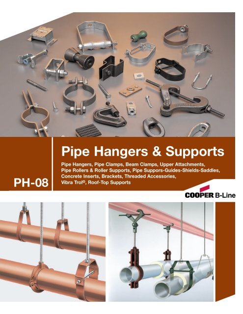
PH-08<br />
<strong>Pipe</strong> <strong>Hangers</strong> & <strong>Supports</strong><br />
<strong>Pipe</strong> <strong>Hangers</strong>, <strong>Pipe</strong> Clamps, Beam Clamps, Upper Attachments,<br />
<strong>Pipe</strong> Rollers & Roller <strong>Supports</strong>, <strong>Pipe</strong> Suppors-Guides-Shields-Saddles,<br />
Concrete Inserts, Brackets, Threaded Accessories,<br />
Vibra Trol ® , Roof-Top <strong>Supports</strong>
INTRODUCTION<br />
<strong>Cooper</strong> B-<strong>Line</strong> ® , Inc. is a leading manufacturer<br />
and fabricator of metal products used in the<br />
support of pipe and equipment for industrial,<br />
commercial, utility, and OEM installations. <strong>Cooper</strong><br />
B-<strong>Line</strong> is proud of the exacting standards of<br />
research, design, engineering, and manufacturing<br />
that go into each and every product that comprise<br />
our pipe hanger product line. Our customers have<br />
access to the most complete support systems<br />
offered in the industry, including pipe hangers,<br />
metal framing, cable tray, slotted angle, fasteners,<br />
telecom, enclosures and anchors.<br />
Many of <strong>Cooper</strong> B-<strong>Line</strong>'s products are listed by<br />
Underwriters' Laboratories, Inc. All <strong>Cooper</strong> B-<strong>Line</strong><br />
products are manufactured to meet or exceed<br />
industry standards set for their design and<br />
manufacture.<br />
<strong>Cooper</strong> B-<strong>Line</strong> products are produced in four<br />
modern plants consisting of over 1,000,000<br />
square feet. These facilities are located in<br />
Highland, Illinois; Troy, Illinois; Reno, Nevada,<br />
and Sherman, Texas. Regional sales and<br />
distribution centers are located throughout the<br />
United States stocking standard <strong>Cooper</strong> B-<strong>Line</strong><br />
products for quick service and delivery.<br />
This catalog is designed to be helpful to<br />
engineers and contractors in the application and<br />
selection of pipe hanger and support products for<br />
construction and maintenance.<br />
If a unique application requires a special product<br />
not included in this catalog, <strong>Cooper</strong> B-<strong>Line</strong><br />
engineering personnel are ready to furnish design<br />
consultation and realistic material estimates. In<br />
addition, sales representatives with engineering<br />
know-how are located throughout the United<br />
States and abroad for your convenience.<br />
Warning<br />
All hanger products in this catalog are intended for<br />
installation and service as illustrated or described. We are<br />
aware that these products have been used successfully for<br />
purposes other than for which they were designed. We also<br />
know that on occasion, these products have failed when<br />
used as tools for erection or for some purpose other than<br />
intended use. We caution against misapplication which may<br />
result in failure or accident.<br />
Examples of this misapplication which can result in failure<br />
include: the use of a beam clamp on a beam other than<br />
described in the catalog; the use of concrete inserts as a<br />
anchor for pulling pipe up to the required elevation; and the<br />
suspension of clevis hangers, one under another, which can<br />
result in the accumulative load greater than the pipe hanger<br />
will support. <strong>Cooper</strong> B-<strong>Line</strong> pipe hanger products are<br />
manufactured in accordance with industry standards. Our<br />
customers should exercise care to use these products<br />
properly so as to avoid an on-the-job accident. Consult the<br />
Home Office for assistance of proper installation and use of<br />
the products in this catalog.<br />
SINCE<br />
1924<br />
MANUFACTURERS STANDARDIZATION SOCIETY<br />
OF THE<br />
VALVE AND FITTING INDUSTRY, INC.<br />
<strong>Cooper</strong> B-<strong>Line</strong><br />
509 West Monroe Street<br />
P.O. Box 326<br />
Highland, Illinois 62249-0326<br />
Phone: 800-851-7415<br />
www.cooperbline.com
Table of Contents<br />
Pictorial Index .................................................. 2-13<br />
Strut Systems Information ............................ 14-15<br />
Technical Data<br />
Materials ............................................................ 16<br />
Corrosion ........................................................... 16<br />
Finishes ........................................................ 16-17<br />
General Information .......................................... 17<br />
Recommended Specifications ................... 18-23<br />
Beam Clamps<br />
C-Clamps ..................................................... 25-29<br />
Bottom Beam Clamps ................................. 29-34<br />
Top Beam Clamps ............................................. 35<br />
Trus Joist & Angle Iron Beam Clamps ............ 36<br />
<strong>Pipe</strong> <strong>Hangers</strong><br />
'J' <strong>Hangers</strong> ........................................................ 39<br />
Clevis <strong>Hangers</strong> ............................................ 40-47<br />
Band <strong>Hangers</strong> .............................................. 48-50<br />
Split Clamps & <strong>Hangers</strong>, Rings .................. 51-58<br />
Wall Mount Lay-In <strong>Hangers</strong> ........................ 55-56<br />
Spring <strong>Hangers</strong> ................................................. 57<br />
<strong>Pipe</strong> Clamps<br />
Risers ............................................................ 61-62<br />
Underground Clamps .................................. 63-64<br />
Clamps ......................................................... 65-69<br />
Straps ........................................................... 70-71<br />
<strong>Pipe</strong> Rollers & Roller <strong>Supports</strong><br />
Roller <strong>Hangers</strong> ............................................. 73-74<br />
Roller <strong>Supports</strong> ............................................ 75-83<br />
Roller Stands ............................................... 84-86<br />
Spring Cushion Roller Hanger ......................... 87<br />
Rollers .......................................................... 88-89<br />
<strong>Pipe</strong> <strong>Supports</strong>, Guides, Shields & Saddles<br />
Calcium Silicate Shields ................................... 91<br />
Stands & <strong>Supports</strong> .................................... 92-103<br />
Guides & Anchors ................................... 104-109<br />
Slides, Shields, Saddles .......................... 110-126<br />
Concrete Inserts<br />
Anchor Bolt Insert .......................................... 129<br />
Spot Inserts & Nuts ................................. 130-136<br />
Anchor Clips .................................................... 137<br />
Brackets<br />
Light Duty ........................................................ 139<br />
Medium Duty ................................................... 140<br />
Heavy Duty ...................................................... 141<br />
Upper Attachments<br />
Ceiling Flange ................................................. 143<br />
Angle <strong>Supports</strong> ........................................ 143-145<br />
Bolted & Welded ...................................... 146-147<br />
Concrete Plates ....................................... 148-150<br />
Rod Beam Attachments ................................. 151<br />
Threaded Accessories<br />
U-Bolts ..................................................... 154-155<br />
Miscellaneous Accessories ............ 153, 156-158<br />
Rods, Couplings & Washers ................... 159-166<br />
Vibra Trol ®<br />
Pads .......................................................... 170-172<br />
Molded Mounts ............................................... 172<br />
Cup Mounts ..................................................... 173<br />
Spring Mounts ......................................... 174-179<br />
Vibration <strong>Hangers</strong> .................................... 180-181<br />
Spring <strong>Hangers</strong> ........................................ 182-188<br />
Vibra Clamp ............................................. 189-190<br />
Isolation <strong>Products</strong> ........................................... 191<br />
Dura-Blok ®<br />
Base ................................................................. 193<br />
Base & Channel ....................................... 194-196<br />
Base & Clamp Riser ....................................... 197<br />
Base & Harness ....................................... 198-199<br />
Base & Rollers ......................................... 200-201<br />
Base Stand ...................................................... 201<br />
Load Distribution Plate .................................. 202<br />
Dura Clean ®<br />
Channel ............................................................ 206<br />
Wall Mount Rail ............................................... 207<br />
U-Bolt & Threaded Rod .................................. 208<br />
Hardware & Spacers ...................................... 209<br />
KwikWire ®<br />
Clamps ............................................................. 212<br />
Wire Rope ........................................................ 212<br />
KwikPak Kits ................................................... 213<br />
Accessories ..................................................... 214<br />
Hanger Assemblies ................................... 216-233<br />
Seicmic Assemblies .................................. 234-238<br />
Reference Data<br />
Metric Conversions ........................................ 239<br />
Miscellaneous Charts ............................. 240-249<br />
MSS & Federal Specifications to<br />
B-<strong>Line</strong> Cross References .................... 250-251<br />
B-<strong>Line</strong> Compliances & Approvals .......... 252-253<br />
Trapeze Hanger Chart .................................... 254<br />
Index ........................................................... 255-256<br />
Your Local Representative Is:<br />
1
Pictorial Index<br />
Pictorial Index<br />
BEAM CLAMPS<br />
Figure B351L<br />
Steel C-Clamp<br />
With Locknut<br />
Page 25<br />
Figure B3036L<br />
Malleable Iron<br />
C-Clamp<br />
With Locknut<br />
Page 25<br />
Figure<br />
B3362 thru B3365<br />
Retaining Strap<br />
Page 26<br />
Figure B3037<br />
Z-Purlin Beam Clamp<br />
Page 26<br />
Figure B3031- 3 /8<br />
Light Duty<br />
Malleable C-Clamp<br />
Page 26<br />
Figure B3033<br />
Wide Jaw<br />
Top Flange C-Clamp<br />
Page 27<br />
Figure B3034<br />
Top Flange C-Clamp<br />
Page 28<br />
Figure B303-B309<br />
Beam Clamp<br />
Page 29<br />
Figure B321 Series<br />
Beam Clamp<br />
Page 29<br />
Figure B3367<br />
Retaining Strap<br />
Page 30<br />
Figure B312<br />
Retaining Strap<br />
Page 30<br />
Figure B3040<br />
Adjustable Beam Clamp<br />
Page 30<br />
Figure B3055<br />
Steel Beam Clamp<br />
Page 31<br />
Figure B3050<br />
Beam Clamp<br />
Page 32<br />
Figure B3054<br />
Malleable Iron<br />
Beam Clamp<br />
Page 33<br />
Figure B3291 thru B3298<br />
UFS Forged Steel<br />
Beam Clamp<br />
Page 34<br />
Figure B3042<br />
Top Beam Clamp<br />
Page 35<br />
Figure B3045<br />
Side Beam Clamp<br />
Page 35<br />
Figure B3052<br />
Trus Joist<br />
Beam Clamp<br />
Page 36<br />
2
Pictorial Index<br />
PIPE HANGERS<br />
Pictorial Index<br />
Figure B3690<br />
Adjustable 'J' Hanger<br />
Page 39<br />
Figure B3690C<br />
Plastic Coated<br />
Adjustable 'J' Hanger<br />
Page 39<br />
Figure B3690F<br />
Felt <strong>Line</strong>d<br />
Adjustable 'J' Hanger<br />
Page 39<br />
Figure B3100<br />
Standard Clevis Hanger<br />
Page 40 & 41 ✸<br />
Figure B3100C<br />
Plastic Coated<br />
Standard Clevis Hanger<br />
Page 40 & 41<br />
Figure B3100F<br />
Felt <strong>Line</strong>d<br />
Standard Clevis Hanger<br />
Page 40 & 41<br />
Figure B3104<br />
Light Duty Clevis Hanger<br />
Page 42 ✸<br />
Figure B3104CT<br />
Copper Tubing<br />
Light Duty Clevis Hanger<br />
Page 43<br />
◆<br />
Figure B3104C<br />
Plastic Coated<br />
Light Duty<br />
Clevis Hanger<br />
Page 42<br />
Figure B3104CTC<br />
Copper Tubing<br />
Plastic Coated<br />
Light Duty<br />
Clevis Hanger<br />
Page 43 ◆<br />
Figure B3104F<br />
Felt <strong>Line</strong>d<br />
Light Duty<br />
Clevis Hanger<br />
Page 42<br />
Figure B3102<br />
AWWA Clevis Hanger<br />
Page 44<br />
Figure B3108<br />
Extended<br />
Clevis Hanger<br />
Page 45<br />
Figure B3109<br />
Flat Top Clevis<br />
Hanger<br />
Page 46<br />
Figure B3106<br />
Vee Bottom<br />
Clevis Hanger<br />
Page 47<br />
Figure B3106V<br />
Plastic <strong>Pipe</strong><br />
Support Channel<br />
Page 47<br />
◆ Dura-Copper Finish<br />
✸ Dura-Green Finish<br />
3
Pictorial Index<br />
Pictorial Index<br />
PIPE HANGERS (Continued)<br />
Figure B3170<br />
Adjustable Swivel Ring<br />
Page 49<br />
Figure B3170NF<br />
Adjustable<br />
Swivel Ring<br />
(NFPA Rod Sizes)<br />
Page 48<br />
Figure B3170NFC<br />
Plastic Coated<br />
Adjustable<br />
Swivel Ring<br />
(NFPA Rod Sizes)<br />
Page 48<br />
Figure B3170NFF<br />
Felt <strong>Line</strong>d<br />
Adjustable<br />
Swivel Ring<br />
(NFPA Rod Sizes)<br />
Page 48<br />
Figure B3170CT<br />
Copper Tubing<br />
Adjustable Swivel Ring<br />
Page 510 ◆<br />
Figure B3170CTC<br />
Copper Tubing<br />
Plastic Coated<br />
Adjustable Swivel Ring<br />
Page 50<br />
◆<br />
Figure B3198H<br />
Hinged Extension<br />
Split <strong>Pipe</strong> Clamp<br />
Page 51<br />
Figure B3198HCT<br />
Copper Tubing<br />
Hinged Extension<br />
Split <strong>Pipe</strong> Clamp<br />
Page 52 ◆<br />
Figure B3198P<br />
Figure B3198R<br />
Extension<br />
Split <strong>Pipe</strong> Clamp<br />
Page 51<br />
Figure B3198RCT<br />
Copper Tubing<br />
Extension<br />
Split <strong>Pipe</strong> Clamp<br />
Page 52 ◆<br />
Figure B3175<br />
Ring and Bolt Hanger<br />
Page 53<br />
Figure B3175CT<br />
Copper Tubing<br />
Ring and Bolt Hanger<br />
Page 53 ◆<br />
Figure B3171<br />
Adjustable Split<br />
Ring Swivel Hanger<br />
Page 54<br />
Figure B386<br />
Suspension Rod<br />
<strong>Pipe</strong> Clamp<br />
Page 55<br />
Figure B3190<br />
Offset 'J' Hook<br />
Page 56<br />
Figure B3191<br />
Straight 'J' Hook<br />
Page 56<br />
◆ Dura-Copper Finish<br />
Figure B3262<br />
Light Duty<br />
Spring Hanger<br />
Page 57<br />
4
Pictorial Index<br />
PIPE HANGERS (Continued)<br />
Pictorial Index<br />
Figure BH-2-4<br />
BH-5-8<br />
BH-9-12<br />
Parallel Strap Hanger<br />
Page 58<br />
Figure BH-2-4-R<br />
BH-5-8-R<br />
BH-9-12-R<br />
Right Angle Strap Hanger<br />
Page 58<br />
Figure BL1400<br />
thru BL1490<br />
Hanger<br />
Page 58<br />
PIPE CLAMPS<br />
Figure B3373<br />
Standard Riser Clamp<br />
Page 61<br />
✸<br />
Figure B3373CT<br />
Copper Tubing<br />
Riser Clamp<br />
Page 62<br />
◆<br />
Figure B3373C<br />
Plastic Coated<br />
Standard Riser Clamp<br />
Page 61<br />
Figure B3373CTC<br />
Copper Tubing<br />
Plastic Coated<br />
Riser Clamp<br />
Page 62<br />
◆<br />
Figure B3132<br />
Two-Bolt<br />
Underground Clamp<br />
Page 63<br />
Figure B3132W<br />
Lug Washer<br />
Page 63<br />
Figure B3134<br />
Four-Bolt<br />
Underground Clamp<br />
Page 64<br />
Figure B3134W<br />
Washer<br />
Page 64<br />
Figure B3140<br />
Standard <strong>Pipe</strong> Clamp<br />
Page 65<br />
✸<br />
Figure B3142<br />
Heavy Duty <strong>Pipe</strong> Clamp<br />
Page 66<br />
Figure B3144<br />
Double Bolt <strong>Pipe</strong> Clamp<br />
Page 67<br />
Figure B3146<br />
Heavy Duty Double<br />
Bolt <strong>Pipe</strong> Clamp<br />
Page 68<br />
Figure B3148<br />
Offset <strong>Pipe</strong> Clamp<br />
Page 69<br />
Figure B3149<br />
Marine Hanger<br />
Page 69<br />
Figure B2400<br />
Standard <strong>Pipe</strong> Strap<br />
Page 70-71<br />
◆ Dura-Copper Finish<br />
✸ Dura-Green Finish<br />
5
Pictorial Index<br />
Pictorial Index<br />
PIPE ROLLERS & ROLLER SUPPORTS<br />
Figure B3110<br />
Adjustable Steel<br />
Yoke <strong>Pipe</strong> Roll<br />
Page 73<br />
✸<br />
Figure B3114<br />
<strong>Pipe</strong> Roll With Sockets<br />
Page 74<br />
Figure B3122<br />
Adjustable Roller Support<br />
Page 75<br />
Figure B3122A<br />
Adjustable Double<br />
Roller Guide<br />
Page 76<br />
Figure B3120<br />
Roller Chair<br />
Page 77<br />
Figure B3124<br />
Roller Support<br />
Page 78<br />
Figure B3126<br />
Roller Support<br />
Page 79<br />
Figure B218<br />
<strong>Pipe</strong> Rollers<br />
Page 80<br />
Figure B219<br />
<strong>Pipe</strong> Rollers<br />
Page 81<br />
Figure B379<br />
<strong>Pipe</strong> Rollers<br />
Page 82<br />
Figure B479<br />
<strong>Pipe</strong> Rollers<br />
Page 83<br />
Figure B3117SL<br />
Steel Roller Stand<br />
Page 84<br />
Figure B3118SL<br />
Adjustable Roller Stand<br />
With Base Plate<br />
Page 85<br />
Figure B3119SL<br />
Roller With Steel<br />
Base Plate<br />
Page 86<br />
Figure B3264<br />
Spring Cushion Hanger<br />
Page 87<br />
Figure B3114R<br />
Long <strong>Pipe</strong> Roll Only<br />
Page 88<br />
Figure B3117R<br />
Short <strong>Pipe</strong> Roll Only<br />
Page 88<br />
✸ Dura-Green Finish<br />
6
Pictorial Index<br />
PIPE SUPPORTS, GUIDES, SHIELDS & SADDLES<br />
Pictorial Index<br />
Figure B3380<br />
thru B3384<br />
360° Calcium Silicate<br />
Shield<br />
Page 91<br />
Figure B3088<br />
Base Stand<br />
Page 92<br />
Figure B3088S<br />
Seismic Base Stand<br />
Page 93<br />
Figure B3088T<br />
Threaded Base Stand<br />
Page 92<br />
Figure B3088ST<br />
Seismic Threaded<br />
Base Stand<br />
Page 93<br />
Figure B3096<br />
Adjustable <strong>Pipe</strong><br />
Saddle Support<br />
Page 94<br />
Figure B3089<br />
<strong>Pipe</strong> Support Adjuster<br />
Page 95<br />
Figure B3090<br />
<strong>Pipe</strong> Saddle Support<br />
With U-Bolt<br />
Page 96-97<br />
Figure B3095<br />
<strong>Pipe</strong> Saddle Support<br />
Page 98-99<br />
Figure B3092<br />
Adjustable <strong>Pipe</strong> Saddle<br />
Support With Yoke<br />
Page 100-101<br />
Figure B3093<br />
Adjustable <strong>Pipe</strong><br />
Saddle Support<br />
Page 102-103<br />
Figure B3281 thru<br />
B3287<br />
<strong>Pipe</strong> Alignment<br />
Guide<br />
Pages 104 & 105<br />
Figure B2417<br />
<strong>Pipe</strong> Guides<br />
Page 106<br />
Figure B3147A<br />
Figure B3147B<br />
Anchor Chairs<br />
Page 106-107<br />
Figure B3256<br />
Hold-Down<br />
Anchor Clamp<br />
Page 108<br />
Figure B3257<br />
Base Plate<br />
Page 109<br />
7
Pictorial Index<br />
Pictorial Index<br />
PIPE SUPPORTS, GUIDES, SHIELDS & SADDLES (Continued)<br />
Figure B3891 thru B3897<br />
<strong>Pipe</strong> Slides<br />
Pages 110-113<br />
Figure B3991 thru<br />
B3993<br />
<strong>Pipe</strong> Slides<br />
Pages 114-117<br />
Figure B3160 thru<br />
B3165<br />
<strong>Pipe</strong> Covering<br />
Protection Saddle<br />
Pages 118-123<br />
Figure B3151<br />
Insulation<br />
Protection Shield<br />
Page 125<br />
Figure B3153<br />
Insulation Protection<br />
Shield With Tabs<br />
Page 125<br />
Figure B3154<br />
Short Insulation<br />
Protection Shield<br />
Page 126<br />
Figure B3155<br />
Short Insulation<br />
Protection Shield<br />
With Tabs<br />
Page 126<br />
CONCRETE INSERTS<br />
Figure B3019<br />
Adjustable Metal<br />
Deck Ceiling Bolt<br />
Page 129<br />
Figure B2501<br />
Light Duty Spot Insert<br />
Page 129<br />
Figure B2500<br />
Light Duty Spot Insert<br />
Page 130<br />
Figure B3014<br />
Malleable Iron<br />
Spot Insert<br />
Page 131<br />
Figure B2505<br />
thru B2508<br />
Spot Insert<br />
Page 132<br />
Figure N2500<br />
Steel Insert Nut<br />
Page 130<br />
Figure B3014N<br />
Malleable Iron Insert Nut<br />
Page 131<br />
Figure B2503<br />
Heavy Duty Spot Insert<br />
Page 133<br />
Figure B22I, B32I, B52I<br />
Continuous Concrete Inserts<br />
Pages 134 - 136<br />
Figure BD40<br />
Fastener Clip<br />
Page 137<br />
Figure BE-5-8<br />
Fastener Clip<br />
Page 137<br />
8
Pictorial Index<br />
BRACKETS<br />
Pictorial Index<br />
Figure B3064<br />
Adjustable Strut Bracket<br />
Page 139<br />
Figure B3068<br />
Light Duty Bracket<br />
Page 139<br />
Figure B3066<br />
Medium Duty Angle<br />
Bracket<br />
Page 140<br />
Figure B3067<br />
Heavy Duty Angle Bracket<br />
Page 141<br />
UPPER ATTACHMENTS<br />
Figure B3199<br />
Ceiling Flange<br />
Page 143<br />
Figure B3199CT<br />
Dura-Copper Coated<br />
Ceiling Flange<br />
Page 143<br />
◆<br />
Figure B3060<br />
Side Beam Angle Clip<br />
Page 143<br />
Figure B3060L<br />
Side Beam Angle Clip<br />
Page 144<br />
Figure B3070<br />
Reversible Angle Clip<br />
Page 144<br />
Figure B3058<br />
Side Beam Connector<br />
Page 145<br />
Figure B3062<br />
Side Beam Bracket<br />
Page 145<br />
Figure B3083<br />
Figure B3083WO<br />
Welded Beam Attachment<br />
Page 146<br />
Figure B3080S (Short)<br />
Figure B3080L (Long)<br />
Structural Welding Lug<br />
Page 147<br />
Figure B3085<br />
Rod Attachment Concrete Plate<br />
Page 148<br />
Figure B3086<br />
Clevis Concrete Plate<br />
Page 149<br />
Figure B3084<br />
Single Lug Concrete Plate<br />
Page 150<br />
Figure B3082<br />
Rod Beam Attachment<br />
Page 151<br />
◆ Dura-Copper Finish<br />
9
Pictorial Index<br />
Pictorial Index<br />
THREADED ACCESSORIES)<br />
Figure B3222<br />
Eye Socket<br />
Page 153<br />
Figure B3200<br />
Weldless Eye Nut<br />
Page 153<br />
Figure B3188<br />
Standard U-Bolt<br />
Pages 153 & 154<br />
Figure B3188C<br />
Plastic Coated<br />
Standard U-Bolt<br />
Pages 153 & 154<br />
Figure B3201<br />
Forged Steel Clevis<br />
Page 156<br />
Figure B3203<br />
Extension Piece<br />
Page 157<br />
Figure B3223<br />
Offset Eye Socket<br />
Page 157<br />
Figure B3224<br />
Hanger Adjuster<br />
Page 158<br />
Figure B3224CT<br />
Dura-Copper Coated<br />
Hanger Adjuster<br />
Page 158 ◆<br />
Figure B3202<br />
Turnbuckle<br />
Page 158<br />
Figure B3205<br />
Machine Threaded Rod<br />
Page 159<br />
Figure ATR<br />
All Threaded Rod<br />
Page 159<br />
Figure B3210<br />
Eye Rod<br />
Page 160<br />
Figure B3211<br />
Welded Eye Rod<br />
Page 160<br />
Figure B3210X<br />
Linked Eye Rod<br />
Page 161<br />
Figure B3211X<br />
Linked Welded Eye Rod<br />
Page 161<br />
Figure B3212<br />
J-Bolt<br />
Page 162<br />
Figure B3213<br />
Coach Screw Rod<br />
Page 162<br />
Figure B3227<br />
Flat End Lag Screw<br />
Page 163<br />
Figure B3228<br />
Hex Head Lag Bolt<br />
Page 163<br />
Figure DS 16 x 2<br />
#16 x 2" Drive Screw<br />
Page 163<br />
◆ Dura-Copper Finish<br />
10
Pictorial Index<br />
THREADED ACCESSORIES (Continued)<br />
Pictorial Index<br />
Figure B655<br />
Steel Rod Coupling<br />
Page 164<br />
Figure B656<br />
Steel Reducer<br />
Rod Coupling<br />
Page 164<br />
Figure B3220<br />
Malleable Iron<br />
Rod Coupling<br />
Page 164<br />
Figure B3248<br />
Steel Washer Plate<br />
Page 165<br />
Figure B200<br />
Square Washer<br />
Page 165<br />
Figure B3234<br />
Bevel Washer<br />
Page 166<br />
VIBRA TROL ®<br />
Figure NNP<br />
Ribbed<br />
Neoprene Pad<br />
Page 170<br />
Figure CNP<br />
Cork and Ribbed<br />
Neoprene Pad<br />
Page 170<br />
Figure CNNK<br />
Cork, Ribbed<br />
Neoprene and Steel<br />
Page 171<br />
Figure VRP<br />
Rubber Cube Pad<br />
Page 171<br />
Figure BVS<br />
Vibra Strip for 1 5 /8" Wide B-<strong>Line</strong> channel<br />
Page 172<br />
Figure NVD<br />
Double Deflection<br />
Page 172<br />
Figure CM<br />
Metal Housing and<br />
Neoprene<br />
Page 173<br />
Figure OML/OM<br />
Spring Mount<br />
Pages 174 & 175<br />
Figure HMLE/HME<br />
Housed 1"<br />
Deflection Mounting<br />
Pages 176 & 177<br />
Figure HMLT/HMT<br />
Housed 1"<br />
Deflection Mounting<br />
Pages 178 & 179<br />
Figure ANH<br />
Acoustical Hanger<br />
Page 180<br />
11
Pictorial Index<br />
Pictorial Index<br />
VIBRA TROL ® (Continued)<br />
Figure RH<br />
Neoprene Hanger<br />
Page 181<br />
Figure HSL/HS<br />
Vibration Spring Hanger<br />
Pages 182 & 183<br />
Figure HESL/HES<br />
Combination Spring & Neoprene<br />
Pages 184 & 185<br />
Figure SHE<br />
Isolation Spring Hanger<br />
Pages 186 & 187<br />
Figure BVT<br />
Vibraclamp Tubing Sizes<br />
Page 189<br />
Figure BVP<br />
Vibraclamp <strong>Pipe</strong> Sizes<br />
Page 190<br />
Figure B1999<br />
Vibra Cushion<br />
Page 191<br />
Figure ISO<br />
ISO <strong>Pipe</strong><br />
Page 191<br />
DURA-BLOK<br />
Bases<br />
Page 193<br />
Base & Short Channel<br />
Page 194<br />
Base & Tall Channel<br />
Page 195<br />
Double Base & Long Channel<br />
Page 196<br />
Base & Clamp Riser<br />
Page 197<br />
Bases & Harness Assembly<br />
Page 198-199<br />
Base & Fixed Height<br />
Roller Assembly<br />
Page 200<br />
Base & Adjustable Height<br />
Roller Assembly<br />
Page 201<br />
12
Pictorial Index<br />
DURA-BLOK (Continued)<br />
Pictorial Index<br />
Base & Adjustabel<br />
Height Channel<br />
Page 201<br />
Load Distribution Plate<br />
Page 202<br />
DURA-CLEAN<br />
Channels<br />
Page 206<br />
Wall Mount<br />
Rails<br />
Page 207<br />
U-Bolts<br />
Page 208<br />
All Threaded<br />
Rods<br />
Page 208<br />
Hardware<br />
Page 209<br />
Spacers<br />
Page 209<br />
KWIKWIRE<br />
Wire Rope<br />
Page 212<br />
KwikPak Kits<br />
Page 213<br />
KwikWire Clamps<br />
Page 212<br />
Air Duct Corner Protector<br />
Page 214<br />
Air Duct Support<br />
Page 214<br />
Wire Rope Cutter<br />
Page 214<br />
13
Strut Systems<br />
<strong>Cooper</strong> B-<strong>Line</strong>'s metal framing support system is designed with many<br />
time-saving features. Fully adjustable and reusable, with a complete line<br />
of channels, fittings, and accessories for multi-purpose applications.<br />
SELECTION CHART<br />
for Channels, Materials and Hole Patterns<br />
Strut Systems<br />
Information<br />
Channel<br />
Type<br />
Channel<br />
Dimensions<br />
Height<br />
Width<br />
Steel<br />
1<br />
Material & Thickness* Channel Hole Pattern **<br />
Alum.<br />
2<br />
Stainless SH S H1 7 /8 TH KO6<br />
Steel<br />
Type<br />
304<br />
3<br />
Type<br />
316<br />
4<br />
B11 3 1 /4" (82.5) 1 5 /8" (41.3) 12 Ga. -- -- -- 1 1 1 -- 1<br />
B12 2 7 /16" (61.9) 1 5 /8" (41.3) 12 Ga. .105 -- -- 1 2 1 1 2 -- 1 2<br />
B22 1 5 /8" (41.3) 1 5 /8" (41.3) 12 Ga. .105 12 Ga. 12 Ga. 1 2 3 4 1 1 2 3 4 1 1 2<br />
B24 1 5 /8" (41.3) 1 5 /8" (41.3) 14 Ga. .080 14 Ga. 14 Ga. 1 2 3 4 1 1 2 3 4 -- 1 2<br />
B26 1 5 /8" (41.3) 1 5 /8" (41.3) 16 Ga. -- -- -- 1 1 1 -- 1<br />
B32 1 3 /8" (34.9) 1 5 /8" (41.3) 12 Ga. -- 12 Ga. -- 1 3 1 1 3 -- 1<br />
B42 1" (25.4) 1 5 /8" (41.3) 12 Ga. -- 12 Ga. -- 1 3 1 1 3 -- 1<br />
B52 13/16" (20.6) 1 5 /8" (41.3) 12 Ga. -- -- -- 1 1 1 -- 1<br />
B54 13/16" (20.6) 1 5 /8" (41.3) 14 Ga. .080 14 Ga. 14 Ga. 1 2 3 4 1 1 2 3 4 -- 1 2<br />
B56 13/16" (20.6) 1 5 /8" (41.3) 16 Ga. -- -- -- 1 1 1 -- 1<br />
Channel Nuts<br />
B2000 Series<br />
Schedule 40 <strong>Pipe</strong> Clamps<br />
Size and Part Number<br />
Thread With Without Twirl<br />
Size Spring Spring Nut<br />
1/4"-20 N224 N224WO TN224<br />
3/8"-16 N228 N228WO TN228<br />
1/2"-13 N225 N225WO TN225<br />
5/8"-11 N255 N255WO --<br />
3/4"-10 N275 N275WO --<br />
Available Finishes: Electro-Galvanized<br />
Combo Nut Washers<br />
Part<br />
Number<br />
Thread<br />
Size<br />
NW524 1/4"-20<br />
NW528 3/8"-16<br />
NW525 1/2"-13<br />
Available Finishes: Electro-Galvanized<br />
Copper Tubing Clamps<br />
Dura Copper ®<br />
Part Nominal Mat'l<br />
No. Tubing Size Ga.<br />
B2026DCU 1/2" (15) 16<br />
B2008DCU 3/4" (20) 16<br />
B2030DCU 1" (25) 14<br />
B2032DCU 1 1 /4" (32) 14<br />
B2011DCU 1 1 /2" (40) 14<br />
B2038DCU 2" (50) 12<br />
B2042DCU 2 1 /2" (60) 12<br />
B2046DCU 3" (80) 12<br />
B2050DCU 3 1 /2" (90) 12<br />
B2054DCU 4" (100) 11<br />
Part Nomina l Mat'l<br />
No. <strong>Pipe</strong> Size Ga.<br />
B2001 3/8" (10) 16<br />
B2008 1/2" (15) 16<br />
B2009 3/4" (20) 14<br />
B2010 1" (25) 14<br />
B2011 1 1 /4" (32) 14<br />
B2012 1 1 /2" (40) 12<br />
B2013 2" (50) 12<br />
B2014 2 1 /2" (60) 12<br />
B2015 3" (80) 12<br />
B2016 3 1 /2" (90) 11<br />
B2017 4" (100) 11<br />
B2018 4 1 /2" (115) 11<br />
B2019 5" (125) 11<br />
B2020 6" (150) 11<br />
B2021 7" (175) 11<br />
B2022 8" (200) 11<br />
Available Finishes: Electro-Galvanized, Aluminum, Stainless,<br />
Dura-Copper Painted, Hot-Dip Galvanized and PVC coated.<br />
Nut and bolts are included with all two-piece clamps.<br />
** Add “PA” to Part No. for Pre-assembled<br />
All dimensions in charts and on drawings are in inches. Dimensions shown in parentheses are in millimeters unless otherwise specified.<br />
14
Strut Systems<br />
Below are some basic clamp and cushions to be used with a strut system. For the industry's most complete<br />
line of strut and strut fittings, refer to <strong>Cooper</strong> B-<strong>Line</strong>'s Strut Systems Engineering Catalog.<br />
B2000 Series<br />
O.D. <strong>Pipe</strong> Clamps<br />
Part O.D. Size Mat'l<br />
No. (Outside Dia.) Ga.<br />
B2023 1/4" (6.3) 16<br />
B2024 3/8" (9.5) 16<br />
B2025 1/2" (12.7) 16<br />
B2026 5/8" (15.9) 16<br />
B2027 3/4" (19.0) 16<br />
B2028 7/8" (22.2) 16<br />
B2029 1" (25.4) 14<br />
B2030 1 1 /8" (28.6) 14<br />
B2031 1 1 /4" (31.7) 14<br />
B2032 1 3 /8" (34.9) 14<br />
B2004 1 1 /2" (38.1) 14<br />
B2011 1 5 /8" (41.3) 14<br />
B2005 1 3 /4" (44.4) 12<br />
B2036 1 7 /8" (47.6) 12<br />
B2037 2" (50.8) 12<br />
B2038 2 1 /8" (54.0) 12<br />
B2039 2 1 /4" (57.1) 12<br />
B-LINE<br />
BVP150<br />
1 1/2” I.P.<br />
BVT & BVP<br />
Series<br />
Vibra-Clamps ®<br />
For Copper Tubing & OD Sizes<br />
Catalog Copper & Steel Nominal<br />
No. OD Tubing Size Copper Size<br />
BVT025 1/4" (6.3) -- --<br />
BVT037 3/8" (9.5) 1/4" (6)<br />
BVT050 1/2" (12.7) 3/8" (10)<br />
BVT062 5/8" (15.9) 1/2" (15)<br />
BVT075 3/4" (19.0) 5/8" (17)<br />
BVT087 7/8" (22.2) 3/4" (20)<br />
BVT100 1" (25.4) -- --<br />
BVT112 1 1 /8" (28.6) 1" (25)<br />
BVT125 1 1 /4" (31.7) -- --<br />
BVT137 1 3 /8" (34.9) 1 1 /4" (32)<br />
BVT150 1 1 /2" (38.1) -- --<br />
BVT162 1 5 /8" (41.3) 1 1 /2" (40)<br />
BVT175 1 3 /4" (44.4) -- --<br />
BVT187 1 7 /8" (47.6) -- --<br />
BVT200 2" (50.8) -- --<br />
BVT212 2 1 /8" (54.0) 2" (50)<br />
BVT225 2 1 /4" (57.1) -- --<br />
BVT250 2 1 /2" (63.5) -- --<br />
BVT262 2 5 /8" (66.7) 2 1 /2" (65)<br />
BVT300 3" (76.2) -- --<br />
BVT312 3 1 /8" (79.4) 3" (80)<br />
BVT362 3 5 /8" (92.1) 3 1 /2" (90)<br />
BVT400 4" (101.6) -- --<br />
BVT412 4 1 /8" (104.8) 4" (100)<br />
BVT612 6 1 /8" (155.6) 6" (150)<br />
Part O.D. Size Mat'l<br />
No. (Outside Dia.) Ga.<br />
B2013 2 3 /8" (60.3) 12<br />
B2041 2 1 /2" (63.5) 12<br />
B2042 2 5 /8" (66.7) 12<br />
B2043 2 3 /4" (69.8) 12<br />
B2014 2 7 /8" (73.0) 12<br />
B2045 3" (76.2) 12<br />
B2046 3 1 /8" (79.4) 12<br />
B2047 3 1 /2" (82.5) 12<br />
B2048 3 3 /8" (85.7) 12<br />
B2015 3 1 /2" (88.9) 12<br />
B2050 3 5 /8" (92.1) 11<br />
B2051 3 3 /4" (95.2) 11<br />
B2052 3 7 /8" (98.4) 11<br />
B2016 4" (101.6) 11<br />
B2054 4 1 /8" (104.8) 11<br />
B2055 4 1 /4" (107.9) 11<br />
B2056 4 3 /8" (111.1) 11<br />
B2017 4 1 /2" (114.3) 11<br />
B2058 4 5 /8" (117.5) 11<br />
B2059 4 3 /4" (120.6) 11<br />
B2060 4 7 /8" (123.8) 11<br />
B2061 5" (127.0) 11<br />
B2062 5 1 /8" (130.2) 11<br />
B2063 5 1 /4" (133.3) 11<br />
B2064 5 3 /8" (136.5) 11<br />
B2065 5 1 /2" (139.7) 11<br />
Available for tubing and<br />
pipe sizes 1 /4" to 6", OD<br />
sizes 1 /4" to 6 5 /8". Easy<br />
one tool installation,<br />
dampens vibration and<br />
noise, secures tubing<br />
firmly, and protects<br />
against galvanic<br />
reaction.<br />
Stainless Steel available<br />
For <strong>Pipe</strong> Sizes<br />
Catalog Nominal<br />
No. <strong>Pipe</strong> Size<br />
BVP025 1/4" (6)<br />
BVP037 3/8" (10)<br />
BVP050 1/2" (15)<br />
BVP075 3/4" (20)<br />
BVP100 1" (25)<br />
BVP125 1 1 /4" (32)<br />
BVP150 1 1 /2" (40)<br />
BVP200 2" (50)<br />
BVP250 2 1 /2" (65)<br />
BVP300 3" (80)<br />
BVP350 3 1 /2" (90)<br />
BVP400 4" (100)<br />
BVP500 5" (125)<br />
BVP600 6" (150)<br />
B1999<br />
Vibra-Cushion<br />
• Inhibits Galvanic Reaction<br />
• Reduces Sound & Vibration<br />
• Used on refrigeration, HVAC, copper<br />
tubing, glass pipes & hydraulic lines<br />
Available in 20 Ft. rolls.<br />
For Rigid Conduit or Iron <strong>Pipe</strong><br />
Nominal Length of Use<br />
Size Vibra-Cushion Clamp No.<br />
3/8" (10) 2 1 /8" (54.0) B2002<br />
1/2" (15) 2 5 /8" (66.7) B2009<br />
3/4" (20) 3 1 /4" (82.5) B2031<br />
1" (25) 4 1 /8" (104.8) B2004<br />
1 1 /4" (32) 5 3 /16" (131.8) B2012<br />
1 1 /2" (40) 5 15 /16" (150.8) B2038<br />
2" (50) 7 1 /2" (190.5) B2042<br />
2 1 /2" (65) 9" (228.6) B2046<br />
3" (80) 11" (279.4) B2051<br />
3 1 /2" (90) 12 1 /2" (317.5) B2055<br />
4" (100) 14 1 /2" (368.3) B2059<br />
5" (125) 17 7 /16" (442.9) B2067<br />
6" (150) 20 3 /4" (527.0) B2116<br />
For Thinwall (EMT) Conduit<br />
Nominal Length of Use<br />
Size Vibra-Cushion Clamp No.<br />
3/8" (10) 1 13 /16" (46.0) B2027<br />
1/2" (15) 2 3 /16" (58.7) B2002<br />
3/4" (20) 2 7 /8" (73.0) B2003<br />
1" (25) 3 5 /8" (92.1) B2032<br />
1 1 /4" (32) 4 3 /8" (120.6) B2036<br />
1 1 /2" (40) 5 7 /16" (138.1) B2012<br />
2" (50) 6 7 /8" (174.6) B2013<br />
For Copper Tubing Type L & K<br />
Nominal Length of Use<br />
Size Vibra-Cushion Clamp No.<br />
1/4" (6) 1 3 /16" (30.2) B2026<br />
3/8" (10) 1 9 /16" (39.7) B2027<br />
1/2" (15) 1 7 /8" (47.6) B2028<br />
5/8" (17) 2 5 /16" (58.7) B2029<br />
3/4" (20) 2 3 /4" (69.8) B2030<br />
1" (25) 3 1 /2" (88.9) B2032<br />
1 1 /4" (32) 4 5 /16" (109.5) B2011<br />
1 1 /2" (40) 5 1 /8" (130.2) B2036<br />
2" (50) 6 11 /16" (169.9) B2013<br />
2 1 /2" (65) 8 1 /4" (209.5) B2014<br />
3" (80) 9 13 /16" (249.2) B2048<br />
3 1 /2" (90) 11 3 /8" (288.9) B2052<br />
4" (100) 12 15 /16" (328.6) B2056<br />
5" (125) 6 1 /8" (409.6) B2064<br />
6" (150) 19 1 /4" (488.9) B2112<br />
8" (200) 25 1 /2" (647.7) B2128<br />
All dimensions in charts and on drawings are in inches. Dimensions shown in parentheses are in millimeters unless otherwise specified.<br />
Strut Systems<br />
Information<br />
15
Technical Data<br />
Technical Data<br />
MATERIALS<br />
Carbon Steel<br />
Carbon steel is used in the<br />
manufacture of <strong>Cooper</strong> B-<strong>Line</strong> pipe<br />
hangers and supports. Excellent<br />
strength characteristics and<br />
adaptability to cold forming provide a<br />
wel engineered design. By cold<br />
forming the steel, mechanical<br />
properties are increased, adding to<br />
the structural integrity of the<br />
fabricated hanger.<br />
Stainless Steel<br />
AISI Type 304 and Type 316 are<br />
non-magnetic members of the<br />
austenitic stainless steel group.<br />
Several conditions make the use of<br />
stainless steel ideal. These include<br />
reducing long term maintenance<br />
costs, high ambient temperatures,<br />
appearance, and stable structural<br />
properties such as yield strength,<br />
and high creep resistance.<br />
CORROSION<br />
All metal surfaces exposed to the<br />
environment are affected by<br />
corrosion. Depending on the physical<br />
properties of the metal and its<br />
proximity to other dissimilar metals,<br />
an electrochemical reaction may<br />
occur which causes an attack on the<br />
metal itself, resulting in corrosion.<br />
Chemical corrosion is limited to<br />
highly corrosive environments, high<br />
temperatures, or a combination of<br />
both.<br />
FINISHES<br />
Zinc Coatings<br />
Protective zinc coatings are available<br />
on a number of pipe hangers and<br />
accessories in three basic forms:<br />
Electro-Plated Zinc, Pre-Galvanized,<br />
and Hot-Dip Galvanized After<br />
Fabrication. In all cases, the zinc<br />
protects the steel first as a sacrificial<br />
anode to repair bare areas on cut<br />
edges and gouges.<br />
When exposed to air and moisture,<br />
zinc forms a tough, adherent protective<br />
film consisting of a mixture of zinc<br />
oxides, hydroxides, and carbonates.<br />
The corrosion resistance of zinc is<br />
directly related to its thickness and the<br />
environment. For example a 0.2 mil<br />
(5 µm) coating will last twice as long<br />
as a 0.1 mil (2.5 µm) coating in the<br />
same environment.<br />
Electro-Plated Zinc<br />
(ASTM B 633 SC1 or SC3)<br />
An Electro-Plated process deposits<br />
a coating of zinc on the steel by<br />
electrolysis from a bath of zinc salts.<br />
This coating is pure zinc and adheres<br />
to the steel with a molecular bond. A<br />
maximum of 0.5 mils (12.7 µm) of zinc<br />
can be applied by this method. This<br />
coating is recommended for in-door<br />
use in relatively dry areas.<br />
Pre-Galvanized Zinc<br />
(ASTM A 653 Coating<br />
Designation G90)<br />
Pre-galvanized zinc is produced by<br />
continuously rolling the steel coils or<br />
sheets through molten zinc at the steel<br />
mills. This is also known as "mill-galvanized"<br />
or "hot-dipped mill galvanized".<br />
Coils are then slit to size for fabrication<br />
of pipe hangers. Coating thicknesses<br />
of G90, is 0.90 ounces per square foot<br />
(0.27 kg/m 2 ) of steel surface.<br />
Zn<br />
ZnFe<br />
Fe<br />
Protection of cut edges with zinc coatings.<br />
ZnO<br />
Cut edges and welded areas are<br />
not zinc coated; however, zinc near the<br />
uncoated metal becomes a<br />
sacrificial anode which protects the<br />
bare areas after a short period of time.<br />
Pre-galvanized steel is not<br />
generally recommended for use<br />
outdoors in industrial environments,<br />
but is suitable for extended exposure in<br />
dry or mildly corrosive atmospheres.<br />
Hot-Dip Galvanized After<br />
Fabrication (ASTM A 123)<br />
After a pipe hanger or fitting has been<br />
fabricated, it is completely immersed in<br />
a bath of molten zinc. A metallurgical<br />
bond is formed, resulting in a zinc<br />
coating that completely coats all<br />
surfaces, including edges. Zinc<br />
coatings of this specification have a<br />
minimum thickness of 1.50 ounces per<br />
square foot (0.45 kg/m 2 ) on each side<br />
or a total of 3.0 ounces per square foot<br />
(0.9 kg/m 2 ) of steel.<br />
Hot-dip galvanized after fabrication is<br />
recommended for outdoor exposure.<br />
For best results, a zinc rich paint<br />
(available from <strong>Cooper</strong> B-<strong>Line</strong>) should<br />
be applied to field cuts. The zinc rich<br />
paint will provide immediate protection<br />
for field cuts and eliminate the short<br />
time period for galvanic action to "heal"<br />
the damaged coating.<br />
Plastic Coating<br />
Some products offered by <strong>Cooper</strong><br />
B-<strong>Line</strong> are plastic or vinyl coated for<br />
prevention of galvanic reaction between<br />
materials or for noise reduction. These<br />
coated products can also be used<br />
where contact between glass pipe and<br />
hanger is not desirable. Felt lined<br />
hangers may be substituted for same<br />
purpose.<br />
Red Primer<br />
A corrosion resistant metal primer<br />
containing rust inhibitive pigments.<br />
16
Technical Data<br />
Dura-Copper ® and<br />
Dura-Green ® Epoxy Coatings<br />
Dura-Copper ® and Dura-Green ® are<br />
water borne epoxy coatings applied to<br />
<strong>Cooper</strong> B-<strong>Line</strong> products by a precisely<br />
controlled cathodic electro-deposition<br />
process. This process is accomplished<br />
using a conveyor to transport parts<br />
through several cleaning, phosphatizing<br />
and application stages prior to being<br />
baked (See diagram below).<br />
This custom designed paint system is<br />
used for painting all copper painted<br />
hanger parts and all green channel,<br />
slotted angle and fittings.<br />
Samples are selected on a routine<br />
basis for Salt Spray (fog) testing to<br />
verify the quality of the finish. These<br />
tests are performed in accordance with<br />
ASTM B 117-73 and evaluated and<br />
rated according to ASTM D 1654-79<br />
(Tables 1 & 2). The Dura-Copper ® and<br />
Dura-Green ® Epoxy coatings have<br />
been tested and listed by Underwriters<br />
Laboratories in accordance with<br />
"Standard for <strong>Pipe</strong> Hanger Equipment<br />
for Fire Protection Service, UL 203"<br />
and meet or exceed all requirements of<br />
Federal Specification TT-C-490B<br />
Paragraph 3.<br />
Quality Assurance<br />
<strong>Cooper</strong> B-<strong>Line</strong> System's Quality<br />
Assurance Program has been<br />
developed and implemented for<br />
compliance to various industry<br />
standards and specifications.<br />
DURA-COPPER ® & DURA-GREEN ® EPOXY COATING PROCESS<br />
TANK 1 TANK 2<br />
Parts are thoroughly<br />
cleaned applied to<br />
Rinse is<br />
and phosphatized.<br />
remove<br />
insoluble salts<br />
and unreacted<br />
phosphates.<br />
TANK 3<br />
Phosphatized<br />
sealer is applied<br />
to insure<br />
corrosion resistance<br />
and paint<br />
adhesion.<br />
TANK 4<br />
TANK 5<br />
The material Deionized rinse<br />
moves through prepares the<br />
clear water metal for the<br />
rinse to remove cathodic<br />
excess phosphates.<br />
electro-coating.<br />
TANK 6<br />
TANK 7<br />
The electrocoating<br />
tank post rinse<br />
The first<br />
applies a removes any<br />
uniform coat of unelectrically<br />
epoxy paint to attracted<br />
the entire surface.<br />
solids.<br />
TANK 8<br />
The final rinse<br />
insures a<br />
smooth,<br />
nonblemish<br />
finish.<br />
BAKE OVEN<br />
The curing<br />
process takes<br />
20 minutes at a<br />
baking<br />
temperature of<br />
375°F (199°C).<br />
Technical Data<br />
SALT SPRAY TEST RESULTS<br />
Dura-Copper ®<br />
Epoxy<br />
Copper Plating<br />
Dura-Copper ®<br />
out performs<br />
Copper Plating<br />
4 to 1<br />
Elapsed Time<br />
(1) All salt spray (fog) tests conducted in accordance with ASTM B 117-73 and evaluated and rated<br />
according to ASTM D 1654-79 Tables 1 & 2. Tests were performed and certified by an independent testing laboratory.<br />
General Information<br />
Torque<br />
The torque values in this catalog are to be used as a guide only. The relationship between the applied torque or<br />
torque wrench reading and the actual tension created in the bolt may be substantially different. Important factors<br />
affecting torque-tension relationships include friction under the bolt head or nut, hole tolerances, and torque<br />
wrench tolerances. Accuracy of many commercial torque wrenches may vary as much as plus or minus 25%.<br />
Charts and Tables<br />
Charts and tables in this section are compiled from information published by nationally recognized organizations<br />
and are intended for use as a guide only. <strong>Cooper</strong> B-<strong>Line</strong> recommends that users of this information determine<br />
the validity of such information as applied to their own applications.<br />
<strong>Cooper</strong> B-<strong>Line</strong>, Inc. reserves the right to make specification changes without notice.<br />
17
Technical Data<br />
Part I - GENERAL<br />
1.01 SECTION INCLUDES<br />
A. The work covered under this section consists of the furnishing of all necessary labor,<br />
supervision, materials, equipment, and services to completely execute the pipe hanger and<br />
supports as described in this specification.<br />
1.02 REFERENCES<br />
SECTION 15140 - PIPE HANGERS AND SUPPORTS<br />
Technical Data<br />
A. ASTM B 633 - Specification for Electrodeposited Coatings of Zinc on Iron and Steel.<br />
B. ASTM A 123 - Specification for Zinc (Hot-Dip Galvanized) Coatings on Iron and Steel <strong>Products</strong>.<br />
C. ASTM A 653 - Specification for Steel Sheet, Zinc-Coated (Galvanized) or Zinc-Iron<br />
Alloy-Coated (Galvannealed) by the Hot-Dip Process.<br />
D. ASTM A 1011 - Specification for Steel, Sheet and Strip, Hot-Rolled, Carbon, Structural,<br />
High-Strength Low-Alloy, and High-Strength Low-Alloy with Improved Formability.<br />
E. MSS SP-58 - Manufacturers Standardization Society: <strong>Pipe</strong> <strong>Hangers</strong> and <strong>Supports</strong> - Materials,<br />
Design, and Manufacture.<br />
F. MSS SP-69 - Manufacturers Standardization Society: <strong>Pipe</strong> <strong>Hangers</strong> and <strong>Supports</strong> - Selection<br />
and Application.<br />
G. NFPA 13 - Installation of Sprinkler Systems.<br />
1.03 QUALITY ASSURANCE<br />
A. <strong>Hangers</strong> and supports used in fire protection piping systems shall be listed and labeled by<br />
Underwriters Laboratories.<br />
B. Steel pipe hangers and supports shall have the manufacturers name, part number, and<br />
applicable size stamped in the part itself for identification.<br />
C. <strong>Hangers</strong> and supports shall be designed and manufactured in conformance with MSS SP-58.<br />
D. <strong>Supports</strong> for sprinkler piping shall be in conformance with NFPA 13.<br />
1.04 SUBMITTALS<br />
A. Submit product data on all hanger and support devices, including shields and attachment<br />
methods. Product data to include, but not limited to materials, finishes, approvals, load<br />
ratings, and dimensional information.<br />
Part II - PRODUCTS<br />
2.01 ACCEPTABLE MANUFACTURERS<br />
A. Manufacturer: Subject to compliance with these specifications, pipe hanger and support<br />
systems shall be as manufactured by <strong>Cooper</strong> B-<strong>Line</strong>, Inc.<br />
2.02 PIPE HANGERS AND SUPPORTS<br />
A. <strong>Hangers</strong><br />
1. Uninsulated pipes 2 inch and smaller:<br />
a. Adjustable steel swivel ring (band type) hanger, <strong>Cooper</strong> B-<strong>Line</strong> B3170.<br />
b. Adjustable steel swivel J-hanger, <strong>Cooper</strong> B-<strong>Line</strong> B3690.<br />
c. Malleable iron ring hanger, <strong>Cooper</strong> B-<strong>Line</strong> B3198R or hinged ring hanger, B3198H.<br />
d. Government type hanger, <strong>Cooper</strong> B-<strong>Line</strong> B3225 or B3226.<br />
e. Adjustable steel clevis hanger, <strong>Cooper</strong> B-<strong>Line</strong> B3104 or B3100.<br />
18
Technical Data<br />
2. Uninsulated pipes 2 1 /2 inch and larger:<br />
a. Adjustable steel clevis hanger, <strong>Cooper</strong> B-<strong>Line</strong> B3100.<br />
b. <strong>Pipe</strong> roll with sockets, <strong>Cooper</strong> B-<strong>Line</strong> B3114.<br />
c. Adjustable steel yoke pipe roll, <strong>Cooper</strong> B-<strong>Line</strong> B3110.<br />
3. Insulated pipe - Hot or steam piping:<br />
a. 2 inch and smaller pipes: use adjustable steel clevis with galvanized sheet metal<br />
shield, <strong>Cooper</strong> B-<strong>Line</strong> B3100 with B3151 or B3153 series.<br />
b. 2 1 /2 inch and larger pipes:<br />
i. Adjustable steel yoke pipe roll with pipe covering protection saddle, <strong>Cooper</strong><br />
B-<strong>Line</strong> B3110 with B3160 - B3165 series.<br />
ii. <strong>Pipe</strong> roll with sockets with pipe covering protection saddle, <strong>Cooper</strong> B-<strong>Line</strong><br />
B3114 with B3160 - B3165 series.<br />
4. Insulated pipe - Cold or chilled water piping:<br />
a. 5 inch and smaller pipes: use adjustable steel clevis with galvanized sheet metal<br />
shield, <strong>Cooper</strong> B-<strong>Line</strong> B3100 with B3151 or B3153 series.<br />
b. 6 inch and larger pipes:<br />
i. Adjustable steel yoke pipe, <strong>Cooper</strong> B-<strong>Line</strong> B3110, with B3380CW - B3384CW<br />
calcium silicate shield.<br />
ii. <strong>Pipe</strong> roll with sockets, <strong>Cooper</strong> B-<strong>Line</strong> B3114, with B3380CW - B3384CW calcium<br />
silicate shield.<br />
Technical Data<br />
B. PIPE CLAMPS<br />
1. When flexibility in the hanger assembly is required due to horizontal movement, use<br />
pipe clamps with weldless eye nuts, <strong>Cooper</strong> B-<strong>Line</strong> B3140 or B3142 with B3200. For<br />
insulated lines use double bolted pipe clamps, <strong>Cooper</strong> B-<strong>Line</strong> B3144 or B3146 with B3200.<br />
C. MULTIPLE OR TRAPEZE HANGERS<br />
1. Trapeze hangers shall be constructed from 12 gauge roll formed ASTM A 1011 SS Gr. 33<br />
structural steel channel, 1 5 /8” x 1 5 /8” minimum, <strong>Cooper</strong> B-<strong>Line</strong> B22 strut or stronger as<br />
required.<br />
2. Mount pipes to trapeze with two piece pipe straps sized for outside diameter of pipe,<br />
<strong>Cooper</strong> B-<strong>Line</strong> B2000 series.<br />
3. For pipes subjected to axial movement:<br />
a. Strut mounted roller support, <strong>Cooper</strong> B-<strong>Line</strong> B3126. Use pipe protection shield or<br />
saddles on insulated lines.<br />
b. Strut mounted pipe guide, <strong>Cooper</strong> B-<strong>Line</strong> B2417.<br />
D. WALL SUPPORTS<br />
1. <strong>Pipe</strong>s 4 inch and smaller:<br />
a. Carbon steel hook, <strong>Cooper</strong> B-<strong>Line</strong> B3191.<br />
b. Carbon steel J-hanger, <strong>Cooper</strong> B-<strong>Line</strong> B3690.<br />
2. <strong>Pipe</strong>s larger than 4 inch:<br />
a. Welded strut bracket and pipe straps, <strong>Cooper</strong> B-<strong>Line</strong> B3064 and B2000 series.<br />
b. Welded steel brackets, <strong>Cooper</strong> B-<strong>Line</strong> B3066 or B3067, with roller chair or adjustable<br />
steel yoke pipe roll. <strong>Cooper</strong> B-<strong>Line</strong> B3120 or B3110. Use pipe protection shield or<br />
saddles on insulated lines.<br />
19
Technical Data<br />
E. FLOOR SUPPORTS<br />
1. Hot piping under 6 inch and all cold piping:<br />
a. Carbon steel adjustable pipe saddle and nipple attached to steel base stand sized<br />
for pipe elevation, <strong>Cooper</strong> B-<strong>Line</strong> B3093 and B3088T or B3090 and B3088. <strong>Pipe</strong> saddle<br />
shall be screwed or welded to appropriate base stand.<br />
2. Hot piping 6 inch and larger:<br />
a. (Adjustable) Roller stand with base plate, <strong>Cooper</strong> B-<strong>Line</strong> B3117SL (or B3118SL).<br />
b. Adjustable roller support and steel support sized for elevation, <strong>Cooper</strong> B-<strong>Line</strong> B3124<br />
F. VERTICAL SUPPORTS<br />
1. Steel riser clamp sized to fit outside diameter of pipe, <strong>Cooper</strong> B-<strong>Line</strong> B3373 or B3374.<br />
Technical Data<br />
G. COPPER TUBING SUPPORTS<br />
1. <strong>Hangers</strong> shall be sized to fit copper tubing outside diameters.<br />
a. Adjustable steel swivel ring (band type) hanger, <strong>Cooper</strong> B-<strong>Line</strong> B3170CT.<br />
b. Malleable iron ring hanger, <strong>Cooper</strong> B-<strong>Line</strong> B3198CT or hinged ring hanger B3198HCT.<br />
c. Government type hanger, <strong>Cooper</strong> B-<strong>Line</strong> B3225CT or B3226CT.<br />
d. Adjustable steel clevis hanger, <strong>Cooper</strong> B-<strong>Line</strong> B3104CT.<br />
H. PLASTIC PIPE SUPPORTS<br />
1. V-bottom clevis hanger with galvanized 18 gauge continuous support channel, <strong>Cooper</strong><br />
B-<strong>Line</strong> B3106 and B3106V, to form a continuous support system for plastic pipe or flexible<br />
tubing.<br />
I. SUPPLEMENTARY STRUCTURAL SUPPORTS<br />
1. Design and fabricate supports using structural quality steel bolted framing materials<br />
as manufactured by <strong>Cooper</strong> B-<strong>Line</strong>. Channels shall be roll formed, 12 gauge ASTM<br />
A 1011 SS Grade 33 steel, 1 5 /8” x 1 5 /8” or greater as required by loading conditions.<br />
Submit designs for pipe tunnels, pipe galleries, etc., to engineer for approval. Use<br />
clamps and fittings designed for use with the strut system.<br />
2.04 UPPER ATTACHMENTS<br />
A. BEAM CLAMPS<br />
1. Beam clamps shall be used where piping is to be suspended from building steel.<br />
Clamp type shall be selected on the basis of load to be supported, and load configuration.<br />
2. C-Clamps shall have locknuts and cup point set screws, <strong>Cooper</strong> B-<strong>Line</strong> B351L, or B3036L.<br />
Top flange C-clamps shall be used when attaching a hanger rod to the top flange of<br />
structural shapes, <strong>Cooper</strong> B-<strong>Line</strong> B3034 or B3033. Refer to manufacturers’<br />
recommendation for setscrew torque. Retaining straps shall be used to maintain the<br />
clamp’s position on the beam where required.<br />
3. Center loaded beam clamps shall be used where specified. Steel clamps shall be <strong>Cooper</strong><br />
B-<strong>Line</strong> B3050 or B3055. Malleable iron or forged steel beam clamps with cross bolt shall<br />
be <strong>Cooper</strong> B-<strong>Line</strong> B3054 or B3291 - B3297 series as required to fit beams.<br />
B. CONCRETE INSERTS<br />
1. Cast in place spot concrete inserts shall be used where applicable, either steel or<br />
malleable iron body, <strong>Cooper</strong> B-<strong>Line</strong> B2500 or B3014. Spot inserts shall allow for lateral<br />
adjustment and have means for attachment to forms. Select insert nuts to suit<br />
threaded hanger rod sizes, <strong>Cooper</strong> B-<strong>Line</strong> N2500 or B3014N series.<br />
20
Technical Data<br />
2. Continuous concrete inserts shall be used where applicable. Channels shall be 12<br />
gauge, ASTM A 1011 SS Grade 33 structural quality carbon steel, complete with<br />
styrofoam inserts and end caps with nail holes for attachment to forms. The<br />
continuous concrete insert shall have a load rating of 2,000 lbs/ft. in concrete,<br />
<strong>Cooper</strong> B-<strong>Line</strong> B22I, B32I, or B52I (B52I is limited to 1,500 lbs/ft.). Select channel nuts<br />
suitable for strut and rod sizes.<br />
2.05 VIBRATION ISOLATION AND SUPPORTS<br />
A. For refrigeration, air conditioning, hydraulic, pneumatic, and other vibrating system<br />
applications, use a clamp that has a vibration dampening insert and a nylon inserted<br />
locknut. For copper and steel tubing use <strong>Cooper</strong> B-<strong>Line</strong> BVT series VibraClamps, for pipe<br />
sizes use BVP series.<br />
B. For larger tubing or piping subjected to vibration, use neoprene or spring hangers<br />
as required.<br />
C. For base mounted equipment use vibration pads, molded neoprene mounts, or spring<br />
mounts as required.<br />
Technical Data<br />
D. Vibration isolation products as manufactured by <strong>Cooper</strong> B-<strong>Line</strong>, VibraTrol systems.<br />
2.06 ACCESSORIES<br />
A. Hanger rods shall be threaded both ends, <strong>Cooper</strong> B-<strong>Line</strong> B3205, or continuous threaded rods<br />
of circular cross section. Use adjusting locknuts at upper attachments and hangers.<br />
No wire, chain, or perforated straps are allowed.<br />
B. Shields shall be 180° galvanized sheet metal, 12 inch minimum length, 18 gauge minimum<br />
thickness, designed to match outside diameter of the insulated pipe, <strong>Cooper</strong> B-<strong>Line</strong> B3151.<br />
C. <strong>Pipe</strong> protection saddles shall be formed from carbon steel, 1 /8 inch minimum thickness,<br />
sized for insulation thickness. Saddles for pipe sizes greater than 12 inch shall have a<br />
center support rib.<br />
2.07 FINISHES<br />
INDOOR FINISHES<br />
A. <strong>Hangers</strong> and clamps for support of bare copper piping shall be coated with copper colored<br />
epoxy paint, <strong>Cooper</strong> B-<strong>Line</strong> Dura-Copper. Additionally a plastic coating or a felt lining in<br />
hanger can be used.<br />
B. <strong>Hangers</strong> for other than bare copper pipe shall be zinc plated in accordance with ASTM<br />
B 633 - SC3 or shall have an electro-deposited green epoxy finish, <strong>Cooper</strong> B-<strong>Line</strong> Dura-Green.<br />
C. Strut channels shall be pre-galvanized in accordance with ASTM A 653 G90 or have<br />
an electro-deposited green epoxy finish, <strong>Cooper</strong> B-<strong>Line</strong> Dura-Green.<br />
OUTDOOR AND CORROSIVE AREA FINISHES<br />
D. <strong>Hangers</strong> and strut located outdoors shall be hot dip galvanized after fabrication in<br />
accordance with ASTM A 123. All hanger hardware shall be hot-dip galvanized or<br />
stainless steel. Zinc plated hardware is not acceptable for outdoor or corrosive use.<br />
E. <strong>Hangers</strong> and strut located in corrosive areas shall be Type 304 (316) stainless steel<br />
with stainless steel hardware.<br />
21
Technical Data<br />
Part III - EXECUTION<br />
3.01 PIPE HANGERS AND SUPPORTS<br />
A. <strong>Pipe</strong> shall be adequately supported by pipe hanger and supports specified in PART II -<br />
PRODUCTS. <strong>Hangers</strong> for insulated pipes shall be sized to accommodate insulation<br />
thickness.<br />
B. Horizontal steel piping shall be supported in accordance with MSS SP-69 Tables 3 and 4,<br />
excerpts of which follow below:<br />
NOMINAL PIPE SIZE ROD DIAMETER MAXIMUM SPACING<br />
Technical Data<br />
3 /8” - 1 1 /4” 3 /8” 7’-0”<br />
1 1 /2” 3 /8” 9’-0”<br />
2” 3 /8” 10’-0”<br />
2 1 /2” 1 /2” 11’-0”<br />
3” 1 /2” 12’-0”<br />
3 1 /2” 1 /2” 13’-0”<br />
4” 5 /8” 14’-0”<br />
5” 5 /8” 16’-0”<br />
6” 3 /4” 17’-0”<br />
8” 3 /4” 19’-0”<br />
10” 7 /8” 22’-0”<br />
12” 7 /8” 23’-0”<br />
14” 1” 25’-0”<br />
16” 1” 27’-0”<br />
C. Horizontal copper tubing shall be supported in accordance with MSS SP-69 Tables 3<br />
and 4, excerpts of which follow below:<br />
NOMINAL PIPE SIZE ROD DIAMETER MAXIMUM SPACING<br />
1 /4” - 3 /4” 3 /8” 5’-0”<br />
1” 3 /8” 6’-0”<br />
1 1 /4” 3 /8” 7’-0”<br />
1 1 /2” 3 /8” 8’-0”<br />
2” 3 /8” 8’-0”<br />
2 1 /2” 1 /2” 9’-0”<br />
3” 1 /2” 10’-0”<br />
3 1 /2” 1 /2” 11’-0”<br />
4” 1 /2” 12’-0”<br />
5” 1 /2” 13’-0”<br />
6” 5 /8” 14’-0”<br />
8” 3 /4” 16’-0”<br />
D. Provide means of preventing dissimilar metal contact such as plastic coated hangers,<br />
copper colored <strong>Cooper</strong> B-<strong>Line</strong> Dura-Copper epoxy paint, or non-adhesive isolation tape<br />
(<strong>Cooper</strong> B-<strong>Line</strong> Iso-<strong>Pipe</strong>). Galvanized felt isolators sized for copper tubing may also be used,<br />
<strong>Cooper</strong> B-<strong>Line</strong> B3195CT.<br />
22
Technical Data<br />
E. Support horizontal cast iron pipe adjacent to each hub, with 10 feet maximum spacing<br />
between hangers.<br />
F. Install hangers to provide a minimum of 1 /2 inch space between finished covering and<br />
adjacent work.<br />
G. Place a hanger within 12 inches of each horizontal elbow.<br />
H. Support vertical piping independently of connected horizontal piping. Support vertical<br />
pipes at every (other) floor. Wherever possible, locate riser clamps directly below pipe<br />
couplings or shear lugs.<br />
I. Where several pipes can be installed in parallel and at the same elevation, provide trapeze<br />
hangers as specified in Section 2.02 C. Trapeze hangers shall be spaced according to the<br />
smallest pipe size, or install intermediate supports according to schedule in Section 3.01 B.<br />
J. Do not support piping from other pipes, ductwork or other equipment which is not<br />
building structure.<br />
3.02 CONCRETE INSERTS<br />
A. Provide inserts for placement in formwork before concrete is poured.<br />
Technical Data<br />
B. Provide inserts for suspending hangers from reinforced concrete slabs and sides of<br />
reinforced concrete beams.<br />
C. Where concrete slabs form finished ceilings, provide inserts to be flush with slab surface.<br />
D. Provide hooked rod to concrete reinforcement section for inserts carrying pipe over 4 inch.<br />
23
Beam Clamps<br />
Beam Clamps<br />
Beam clamps offered in this section are designed to provide attachment of hanger rods to structural members without<br />
drilling or welding. A wide range of types and sizes are available for various applications.<br />
Materials<br />
Carbon Steel, Malleable Iron and Forged Steel are used in the manufacturing of beam clamps and accessories. Stainless<br />
steel and other materials are available.<br />
Finishes<br />
The standard finishes for mechanical supports are plain steel (oil coated) sometimes referred to as black and Electro-Plated<br />
Zinc (ASTM B 633 SC3). Hot-Dip Galvanized After Fabrication (ASTM A 123), Red Primer, Plastic Coating and Dura-Green ® .<br />
Other special coatings are available upon request.<br />
Note: Due to the design of some products, (threads, connecting hardware, swivels, etc.) items may<br />
or may not be uniformly coated with special finishes. In some cases, the hanger itself may be coated, however, the<br />
hardware may be supplied Electro-Plated, copper plated, or in stainless steel.<br />
Recommended Setscrew Torque (unless otherwise specified)<br />
1 /4”-20 3 /8”-16 1 /2”-13 5 /8”-11 3 /4”-10<br />
4 ft/lbs (5 Nm) 5 ft/lbs (7 Nm) 11 ft/lbs (15 Nm) 21 ft/lbs (28 Nm) 34 ft/lbs (46 Nm)<br />
Over torqued setscrews will damage beam clamps in this section.<br />
We are aware that torque wrenches are not used or not available in many instances. In the absence of a torque wrench, the<br />
setscrew should be finger tightened to the I-beam and then an additional 1 /4 to 1 /2 turn applied to the setscrew.<br />
Approvals (as noted)<br />
Items in this section are Underwriters' Laboratories Listed and comply with Federal Specification<br />
WW-H-171E & A-A-1192A or Manufacturers Standardization Society MSS SP-69 & SP-58.<br />
All dimensions in charts and on drawings are in inches. Dimensions shown in parentheses are in millimeters unless otherwise specified.<br />
24
Beam Clamps<br />
'B'<br />
'D'<br />
'C'<br />
Setscrew and<br />
Locknut Included<br />
'A'<br />
(Rod Size)<br />
Hanger Rod<br />
Not Included<br />
Figure B351L Steel C-Clamp With Locknut<br />
Material: Steel (Stainless Steel Type 304<br />
available 3 /8" thru 5 /8" rod sizes)<br />
Standard Finish: Plain or Electro-Plated<br />
Service: Designed for attaching a hanger rod<br />
to the flange of a beam.<br />
Ordering: Specify part number and finish. When<br />
Retaining Strap is required, order B3362 thru<br />
B3365 separately. See page 26.<br />
Approvals: B351L ( 3 /8” - 3 /4”), is Underwriters'<br />
Laboratories Listed. Complies with Federal<br />
Specification WW-H-171E & A-A-1192A Type 23<br />
and Manufacturers Standardization Society<br />
MSS SP-69 & SP-58 Type 23.<br />
Part Rod Design Maximum<br />
No. Size Load Iron <strong>Pipe</strong> Size Wt./C<br />
'A' 'B' 'C' 'D' Lbs. kN Per UL Lbs. kg<br />
B351L- 3 /8 3 /8"-16 2 3 /8" (60.3) 2 3 /8" (60.3) 3 /4" (19.0) 300 (0.89) 4" (100) 41 (18.6)<br />
B351L- 1 /2 1 /2"-13 2 3 /8" (60.3) 2 3 /8" (60.3) 3 /4" (19.0) 380 (1.69) 4" (100) 41 (18.6)<br />
B351L- 5 /8 5 /8"-11 2 3 /8" (60.3) 2 1 /4" (57.1) 3 /4" (19.0) 550 (2.44) 6" (150) 60 (27.2)<br />
B351L- 3 /4 3 /4"-10 2 3 /8" (60.3) 2 1 /4" (57.1) 3 /4" (19.0) 630 (2.80) 6" (150) 71 (32.2)<br />
B351L- 7 /8 7 /8"-9 3" (76.2) 3 1 /4" (82.5) 1" (25.4) 1200 (5.34) -- -- 184 (83.4)<br />
Note: See page 24 for recommended setscrew torque.<br />
Beam Clamps<br />
Setscrew and<br />
Locknut Included<br />
'A'<br />
(Rod Size)<br />
Hanger Rod<br />
Not Included<br />
'C'<br />
3/4"<br />
(19.0)<br />
'B'<br />
Material: Malleable Iron<br />
Standard Finish: Plain or Electro-Plated<br />
Service: Designed for attaching a hanger rod to<br />
the flange of a beam.<br />
Ordering: Specify part number and finish.<br />
When Retaining Strap is required, order B3362 thru<br />
B3365 separately. See page 26.<br />
Approvals: B3036L is Underwriters' Laboratories<br />
Listed. Complies with Federal Specification<br />
WW-H-171E & A-A-1192A Type 23 and<br />
Manufacturers Standardization Society MSS SP-69<br />
& SP-58 Type 23.<br />
Figure B3036L Malleable Iron C-Clamp With Locknut<br />
Part Rod Design Maximum<br />
No. Size Load Iron <strong>Pipe</strong> Size Wt./C<br />
'A' 'B' 'C' Lbs. kN Per UL Lbs. kg<br />
B3036L- 3 /8 3 /8"-16 1 3 /4" (44.4) 1 3 /4" (44.4) 300 (0.89) 4" (100) 41 (18.6)<br />
B3036L- 1 /2 1 /2"-13 1 3 /4" (44.4) 1 3 /4" (44.4) 380 (1.69) 5" (125) 41 (18.6)<br />
B3036L- 5 /8 5 /8"-11 2" (50.8) 1 7 /8" (47.6) 530 (2.36) 6" (150) 60 (27.2)<br />
B3036L- 3 /4 3 /4"-10 2" (50.8) 2" (50.8) 530 (2.36) 6" (150) 71 (32.2)<br />
Note: See page 24 for recommended setscrew torque.<br />
All dimensions in charts and on drawings are in inches. Dimensions shown in parentheses are in millimeters unless otherwise specified.<br />
25
Beam Clamps<br />
'B' 3/4"<br />
(19.0)<br />
Material: Steel (Stainless Steel available)<br />
Standard Finish: Pre-Galvanized<br />
Service: Designed for use with B351L and B3036L<br />
C-Clamps.<br />
'L'<br />
Ordering: Specify part number, length 'L', (add 1"<br />
(25.4) minimum to flange width), and finish.<br />
Material Thickness<br />
12 Gauge (2.7)<br />
'A'<br />
Figure B3362, B3363, B3364, B3365 Retaining Strap<br />
Note: Requires field forming on beam.<br />
Wt./C for Length 'L' of<br />
Part 6" (152.4) 8" (203.2) 10" (254.0) 12" (304.8)<br />
No. For Use With 'A' 'B' Lbs. kg Lbs. kg Lbs. kg Lbs. kg<br />
B3362 B351L- 3 /8 & 1 /2 1 1 /4" (31.7) 7 /16" (11.1) 27 (12.2) 35 (15.9) 44 (19.9) 52 (23.6)<br />
B3363 B351L- 5 /8 & 3 /4, 1 1 /4" (31.7) 5 /8" (15.9) 26 (11.8) 35 (15.9) 43 (19.5) 52 (23.6)<br />
B3036L- 3 /8 & 1 /2<br />
B3364 B3036L- 5 /8 & 3 /4 1 1 /4" (31.7) 11 /16" (17.4) 26 (11.8) 35 (15.9) 43 (19.5) 52 (23.6)<br />
B3365 B351L- 7 /8 1 1 /2" (38.1) 3 /4" (19.0) 32 (14.5) 42 (19.0) 52 (23.6) 62 (28.1)<br />
Beam Clamps<br />
3"<br />
(76.2)<br />
Setscrew and<br />
Locknut Included<br />
Material: Malleable Iron<br />
Standard Finish: Plain or Electro-Plated<br />
Service: Designed for attaching a 3 /8"-16 hanger rod<br />
to the bottom flange of a Z-purlin.<br />
Ordering: Specify part number and finish.<br />
Bottom Hanger<br />
Rod Threads<br />
3/8"-16<br />
3 13 /32"<br />
(86.5)<br />
Throat Opening<br />
31/32" (24.6)<br />
Figure B3037 Z-Purlin Malleable C-Clamp<br />
Note: See page 24 for recommended setscrew torque.<br />
Weight: Wt./C 90 Lbs. (40.8 kg)<br />
Design Load: 400 Lbs. (1.78 kN)<br />
Approvals: Underwriters' Laboratories Listed.<br />
Complies with Federal Specification WW-H-171E &<br />
A-A-1192A Type 23 and Manufacturers Standardization<br />
Society MSS SP-69 & SP-58 Type 23.<br />
1 1 /2"<br />
(38.1)<br />
3/4"<br />
(19.0)<br />
1 7 /8"<br />
(47.6)<br />
Figure B3031- 3 /8 Light Duty<br />
Malleable C-Clamp<br />
Throat Opening<br />
11/16" (17.5)<br />
Setscrew and<br />
Locknut Included<br />
Hanger Rod<br />
Not Included<br />
Note: See page 24 for recommended setscrew torque.<br />
Material: Malleable Iron<br />
Standard Finish: Plain or Electro-Plated<br />
Service: Designed for attaching a 3 /8"-16 hanger rod<br />
to the top or bottom flange of a beam or bar joist when<br />
setscrew is in the down position as shown.<br />
Ordering: Specify part number and finish. When<br />
Retaining Strap is required, order B3367 separately.<br />
See Page 30.<br />
Approvals: Underwriters' Laboratories Listed.<br />
Complies with Federal Specification WW-H-171E &<br />
A-A-1192A Type 19 and Manufacturers Standardization<br />
Society MSS SP-69 & SP-58 Type 19.<br />
Weight: Wt./C 25 Lbs. (11.3 kg)<br />
Design Load: 350 Lbs. (1.55 kN)<br />
All dimensions in charts and on drawings are in inches. Dimensions shown in parentheses are in millimeters unless otherwise specified.<br />
26
Beam Clamps<br />
'C'<br />
'D'<br />
Material: Ductile Iron<br />
Standard Finish: Plain or Electro-Plated screw<br />
with Hot-Dipped Galvanized clamp<br />
Throat Opening<br />
1 1 /4" (31.7) for B3033- 3 /8 & 1 /2<br />
1 5 /16" (83.3) for B3033- 5 /8 & 3 /4<br />
Setscrew and<br />
Locknut Included<br />
'B'<br />
'A'<br />
(Rod Size)<br />
Hanger Rod<br />
Not Included<br />
Service: Designed for attaching a hanger rod to<br />
the top or bottom flange of a bar joist or other<br />
structural shapes.<br />
Note: Installation of C-Clamp other than shown<br />
below is not recommended.<br />
Ordering: Specify part number and finish.<br />
When Retaining Strap is required, order B3367<br />
separately. See page 30.<br />
Approvals: Underwriters' Laboratories Listed.<br />
Complies with Federal Specification WW-H-171E<br />
Type 19 & A-A-1192A Type 19 & 23 and<br />
Manufacturers Standardization Society<br />
MSS SP-69 & SP-58 Type 19 & 23.<br />
Top Flange<br />
Attachment<br />
Applications<br />
Beam Clamps<br />
Bottom Flange<br />
Attachment<br />
Applications<br />
Figure B3033 Wide Jaw Reversible C-Clamp<br />
Part Rod Design Maximum<br />
No. Size Load Iron <strong>Pipe</strong> Size Wt./C<br />
'A' 'B' 'C' 'D' Lbs. kN Per UL Lbs. kg<br />
B3033- 3 /8 3 /8"-16 2 1 /4" (57.1) 2" (50.8) 1 1 /8" (28.6) 500 (2.22) 4" (100) 54 (24.5)<br />
B3033- 1 /2 1 /2"-13 2 5 /16" (58.7) 2 3 /16" (55.6) 1 1 /4" (31.7) 810 (3.60) 8" (200) 51 (23.1)<br />
B3033- 5 /8 5 /8"-11 2 5 /8" (66.7) 2 1 /2" (63.5) 1 3 /8" (34.9) 1000 (4.44) 8" (200) 70 (31.7)<br />
B3033- 3 /4 3 /4"-10 2 11 /16" (68.3) 2 1 /2" (63.5) 1 7 /16" (36.5) 1400 (6.23) 10" (250) 98 (44.4)<br />
Note: See page 24 for recommended setscrew torque.<br />
All dimensions in charts and on drawings are in inches. Dimensions shown in parentheses are in millimeters unless otherwise specified.<br />
27
Beam Clamps<br />
Throat<br />
Opening<br />
3/4" (19.0)<br />
B3034- 3 /8" and B3034- 1 /2" sizes<br />
Attach only as shown.<br />
'C'<br />
Setscrew and<br />
Locknut Included<br />
'B'<br />
'D'<br />
'A'<br />
(Rod Size)<br />
Hanger Rod<br />
Not Included<br />
Material: Ductile Iron for 3 /8” & 1 /2” sizes<br />
Malleable Iron for 5 /8” & 3 /4” sizes<br />
Standard Finish: Plain or Electro-Plated screw<br />
with Hot-Dipped Galvanized clamp<br />
Service: Designed for attaching a hanger rod to<br />
the top or bottom flange (for their respective sizes)<br />
of a bar joist or other structural shapes.<br />
Note: Installation of C-Clamps (for their respective<br />
sizes) other than shown is not recommended.<br />
Ordering: Specify part number and finish.<br />
When Retaining Strap is required, order B3367<br />
separately. See page 30.<br />
Approvals: Underwriters' Laboratories Listed<br />
( 3 /8” and 1 /2”only). Complies with Federal<br />
Specification WW-H-171E Type 19 & A-A-1192A<br />
Type 19 & 23 and Manufacturers Standardization<br />
Society MSS SP-69 & SP-58 Type 19 & 23.<br />
Top Flange<br />
Attachment<br />
Applications<br />
Beam Clamps<br />
B3034- 5 /8" and B3034- 3 /4" sizes<br />
Attach only as shown.<br />
'C'<br />
'D'<br />
Bottom Flange<br />
Attachment<br />
Applications<br />
Throat<br />
Opening<br />
3/4" (19.0)<br />
Setscrew and<br />
Locknut Included<br />
'B'<br />
'A'<br />
(Rod Size)<br />
Hanger Rod<br />
Not Included<br />
Figure B3034 C-Clamp<br />
Part Rod Design Maximum<br />
No. Size Load Iron <strong>Pipe</strong> Size Wt./C<br />
'A' 'B' 'C' 'D' Lbs. kN Per UL Lbs. kg<br />
B3034- 3 /8 3 /8"-16 1 5 /8" (41.3) 2" (50.8) 7 /8" (19.0) 560 (2.49) 4" (100) 30 (13.6)<br />
B3034- 1 /2 1 /2"-13 1 13 /16" (46.0) 2 3 /16" (55.6) 1 3 /16" (30.2) 810 (3.60) 8" (200) 47 (21.3)<br />
B3034- 5 /8 5 /8"-11 1 3 /4" (44.5) 2 1 /8" (54.0) 1 1 /4" (31.7) 1000 (4.45) -- -- 58 (26.3)<br />
B3034- 3 /4 3 /4"-10 2" (50.8) 2 1 /4" (57.2) 1 1 /4" (31.7) 1500 (6.67) -- -- 77 (35.0)<br />
Note: See page 24 for recommended setscrew torque.<br />
All dimensions in charts and on drawings are in inches. Dimensions shown in parentheses are in millimeters unless otherwise specified.<br />
28
Beam Clamps<br />
7/8" (22.2)<br />
Maximum<br />
Flange<br />
Thickness<br />
'C'<br />
'T'<br />
2 1 /2"<br />
(63.5)<br />
Figure B303-B309 Beam Clamps<br />
'A'<br />
1 1 /8"<br />
(28.6)<br />
Setscrew<br />
Included<br />
Material: Steel<br />
Standard Finish: Electro-Plated or<br />
Hot-Dip Galvanized<br />
Service: Designed for attaching a hanger rod<br />
to the flange of a beam.<br />
Ordering: Specify part number and finish. When<br />
Retaining Strap is required, order B312 separately.<br />
See page 30.<br />
Recommended Setscrew Torque:<br />
3 /8”-16 = 150 in-lbs (16.9 N•m)<br />
1 /2”-13 = 350 in-lbs (39.5 N•m)<br />
Approvals: Complies with Federal Specification<br />
WW-H-171E & A-A-1192A Type 19 and Manufacturers<br />
Standardization Society MSS SP-69 & SP-58 Type 19.<br />
Part Rod Setscrew Design Load Wt./C<br />
No. Size ‘A’ Size 'C' 'T' Lbs. kN Lbs. kg<br />
B303 1 /4”-20 3 /8”-16 2 5 /16" (58.7) 11 Ga. (3.0) 400 (1.78) 72 (32.6)<br />
B304 5 /16”-18 3 /8”-16 2 5 /16" (58.7) 11 Ga. (3.0) 600 (2.67) 72 (32.6)<br />
B305 3 /8”-16 3 /8”-16 2 5 /16" (58.7) 11 Ga. (3.0) 600 (2.67) 72 (32.6)<br />
B306 3 /8”-16 1 /2”-13 2 7 /16" (61.9) 7 Ga. (4.5) 1100 (4.89) 97 (44.0)<br />
B307 1 /2”-13 1 /2”-13 2 7 /16" (61.9) 7 Ga. (4.5) 1100 (4.89) 97 (44.0)<br />
B308 1 /2”-13 1 /2”-13 2 9 /16" (65.1) 1 /4" (6.3) 1500 (6.67) 133 (60.3)<br />
B309 5 /8”-11 1 /2”-13 2 9 /16" (65.1) 1 /4" (6.3) 1500 (6.67) 133 (60.3)<br />
Beam Clamps<br />
Setscrew<br />
Included<br />
1 11 /16" (42.8)<br />
Maximum<br />
Flange<br />
Thickness<br />
'C'<br />
'T'<br />
3 1 /4"<br />
(82.5)<br />
Figure B321 Series Beam Clamps<br />
'A'<br />
1 5 /8"<br />
(41.3)<br />
Material: Steel<br />
Standard Finish: Electro-Plated or<br />
Hot-Dip Galvanized<br />
Service: Designed for attaching a hanger rod<br />
to the flange of a beam.<br />
Ordering: Specify part number and finish. When<br />
Retaining Strap is required, order B312 separately.<br />
See page 30.<br />
Recommended Setscrew Torque:<br />
1 /2”-13 = 350 in-lbs (39.5 N•m)<br />
5 /8”-11 = 700 in-lbs (79.0 N•m)<br />
Minimum Flange Thickness:<br />
For B321-1 thru B321-3 = 3 /8” (9.5)<br />
For B321-4 & B321-5 = 5 /8” (15.9)<br />
Approvals: Complies with Federal Specification<br />
WW-H-171E & A-A-1192A Type 19 and Manufacturers<br />
Standardization Society MSS SP-69 & SP-58 Type 19.<br />
Part Rod Setscrew Design Load Wt./C<br />
No. Size ‘A’ Size 'C' 'T' Lbs. kN Lbs. kg<br />
B321-1 3 /8”-16 1 /2”-13 3 9 /16" (92.1) 1 /4" (6.3) 1300 (5.78) 187 (84.8)<br />
B321-2 1 /2”-13 1 /2”-13 3 9 /16" (92.1) 1 /4" (6.3) 1400 (6.23) 186 (84.3)<br />
B321-3 5 /8”-11 1 /2”-13 3 9 /16" (92.1) 1 /4" (6.3) 1600 (7.12) 185 (83.9)<br />
B321-4 5 /8”-11 5 /8”-11 3 23 /32" (94.4) 5 /16" (7.9) 1800 (8.00) 239 (108.4)<br />
B321-5 3 /4”-10 5 /8”-11 3 23 /32" (94.4) 5 /16" (7.9) 2000 (8.89) 238 (107.9)<br />
All dimensions in charts and on drawings are in inches. Dimensions shown in parentheses are in millimeters unless otherwise specified.<br />
29
Beam Clamps<br />
'L'<br />
'B' Dia.<br />
Material Thickness<br />
11 Gauge (3.0)<br />
Figure B3367 Retaining Straps<br />
'A'<br />
Note:<br />
Requires<br />
field forming<br />
on beam.<br />
Material: Steel<br />
Standard Finish: Pre-Galvanized<br />
Service: Designed for use with B3031, B3033, and<br />
B3034 C-Clamps.<br />
Ordering: Specify part number, length 'L', (add 2"<br />
(50.8) minimum to flange width), and finish.<br />
Wt./C for Length 'L' of<br />
Part 6" (152.4) 8" (203.2) 10" (254.0) 12" (304.8)<br />
No. For Use With 'A' 'B' Lbs. kg Lbs. kg Lbs. kg Lbs. kg<br />
B3367- 3 /8 B3033- 3 /8, B3034- 3 /8 & B3031- 3 /8 1 1 /4" (31.7) 7 /16" (11.1) 26 (11.8) 35 (15.9) 44 (19.9) 61 (27.6)<br />
B3367- 1 /2 B3033- 1 /2 & B3034- 1 /2 1 1 /4" (31.7) 9 /16" (14.3) 25 (11.3) 34 (15.4) 43 (19.5) 60 (27.2)<br />
B3367- 5 /8 B3033- 5 /8 & B3034- 5 /8 1 1 /4" (31.7) 11 /16" (17.5) 24 (10.9) 33 (14.9) 42 (19.0) 59 (26.7)<br />
B3367- 3 /4 B3033- 3 /4 & B3034- 3 /4 1 1 /4" (31.7) 13 /16" (20.6) 23 (10.4) 32 (14.5) 41 (18.6) 58 (26.3)<br />
Beam Clamps<br />
1 1 /4"<br />
(31.7)<br />
Material Thickness<br />
14 Gauge (1.9)<br />
Figure B312 Retaining Straps<br />
'L'<br />
1/4"<br />
(6.3)<br />
1 3 /4"<br />
(44.4)<br />
1/2"<br />
(12.7)<br />
Part<br />
Wt./C<br />
No. For Flange With 'L' Lbs. kg<br />
B312-6 6" (152.4) 9" (228.6) 22 (10.0)<br />
B312-9 9" (228.6) 12" (304.8) 30 (13.6)<br />
B312-12 12" (304.8) 15" (381.0) 40 (18.1)<br />
B312-15 15" (381.0) 18" (457.2) 49 (22.2)<br />
Material: Steel<br />
Standard Finish: Pre-Galvanized<br />
Service: Designed for use with B303-B309 and<br />
B321 beam clamps.<br />
Ordering: Specify part number and finish.<br />
Notes:<br />
Maximum beam thickness 3 /4” (19.0).<br />
For thicker beams step up one flange width<br />
size.<br />
Requires field forming on beam.<br />
'A'<br />
'A'<br />
(Rod Size)<br />
Hanger Rod<br />
Not Included<br />
J-Hook and Hex<br />
Nut Included<br />
'C'<br />
Center of J-Hook to<br />
bottom of clamp body.<br />
Figure B3040 Adjustable Beam Clamp<br />
'C'<br />
'B'<br />
Steel Size<br />
Material: Steel<br />
Standard Finish: Plain or Electro-Plated<br />
Service: Designed for attaching rod under a beam<br />
flange. Adjustable for 4" (101.6) to 8" (203.2) flange<br />
widths.<br />
Maximum flange thickness 3 /4" (19.0).<br />
Ordering: Specify part number and finish.<br />
Approvals: Complies with Federal Specification<br />
WW-H-171E Type 54 & A-A-1192A Type 27 and<br />
Manufacturers Standardization Society MSS SP-69<br />
& SP-58 Type 27.<br />
Part Rod Size Design Load Wt./C<br />
No. 'A' 'B' 'C' Steel Size Lbs. kN Lbs. kg<br />
B3040- 3 /8 3 /8"-16 2 3 /4" (69.8) 1 13 /16" (46.0) 1 /4" x 1 1 /4" (6.3 x 31.7) 300 (1.33) 120 (54.4)<br />
B3040- 1 /2 1 /2"-13 2 3 /4" (69.8) 1 3 /4" (44.4) 1 /4" x 1 1 /2" (6.3 x 38.1) 700 (3.11) 160 (72.6)<br />
B3040- 5 /8 5 /8"-11 3" (76.2) 1 3 /4" (44.4) 1 /4" x 1 3 /4" (6.3 x 44.4) 1000 (4.45) 216 (98.0)<br />
B3040- 3 /4 3 /4"-10 3 3 /8" (85.7) 1 7 /8" (47.6) 3 /8" x 2 1 /2" (9.5 x 63.5) 1800 (8.00) 442 (200.5)<br />
All dimensions in charts and on drawings are in inches. Dimensions shown in parentheses are in millimeters unless otherwise specified.<br />
30
Beam Clamps<br />
Material: Steel<br />
Standard Finish: Plain or Electro-Plated<br />
Steel Size<br />
Service: Designed for attaching a hanger rod to be<br />
centered under beam flanges. 2" (50.8) vertical<br />
adjustment is provided in the clamp.<br />
'W'<br />
'B'<br />
'C'<br />
Bolt and Nut<br />
Included<br />
Ordering: Specify part number, flange width, and<br />
finish.<br />
Approvals: Complies with Federal Specification<br />
WW-H-171E & A-A-1192A Type 21 and<br />
Manufacturers Standardization Society MSS SP-69 &<br />
SP-58 Type 21.<br />
'A'<br />
(Rod Size)<br />
Hanger Rod<br />
Not Included<br />
'B'<br />
Center of cross bolt<br />
to bottom of side of<br />
hanger rod nut.<br />
Figure B3055 Steel Beam Clamp<br />
NOTE:<br />
Slots on bottom<br />
portions of clamp<br />
halves allow 1” (25.4)<br />
adjustment for<br />
variance in flange<br />
widths<br />
'W'<br />
'A'<br />
(Rod Size)<br />
Hanger Rod<br />
Not Included<br />
Steel Size<br />
Rod Size<br />
Design Load<br />
Part No. 'A' 'B' 'C' Steel Size Lbs. kN<br />
B3055- 3 /8 3 /8"-16 3" (76.2) 4" (101.6) 1 /4" x 1 1 /4" (6.3 x 31.7) 550 (2.44)<br />
B3055- 1 /2 1 /2"-13 3" (76.2) 4" (101.6) 1 /4" x 1 1 /2" (6.3 x 38.1) 850 (3.78)<br />
B3055- 5 /8 5 /8"-11 3 1 /4" (82.5) 4 1 /2" (114.3) 3 /8" x 1 1 /2" (9.5 x 38.1) 1100 (4.89)<br />
B3055- 3 /4 3 /4"-10 3 1 /4" (82.5) 4 1 /2" (114.3) 3 /8" x 2" (9.5 x 50.8) 1500 (6.67)<br />
B3055- 7 /8 7 /8"-9 3 1 /2" (88.9) 5" (127.0) 1 /2" x 2" (12.7 x 50.8) 2600 (11.56)<br />
B3055-1 1"-8 3 1 /2" (88.9) 5 1 /2" (139.7) 1 /2" x 2 1 /2" (12.7 x 63.5) 4300 (19.12)<br />
'B'<br />
'C'<br />
Note:<br />
Box Style<br />
Furnished For<br />
B3055- 3 /8 x 2"<br />
B3055- 3 /8 x 3"<br />
B3055- 3 /8 x 4"<br />
B3055- 1 /2 x 2"<br />
B3055- 1 /2 x 3"<br />
B3055- 1 /2 x 4"<br />
B3055- 5 /8 x 2"<br />
B3055- 5 /8 x 3"<br />
B3055- 5 /8 x 4"<br />
B3055- 3 /4 x 2"<br />
B3055- 3 /4 x 3"<br />
B3055- 3 /4 x 4"<br />
B3055- 7 /8 x 3"<br />
B3055- 7 /8 x 4"<br />
B3055- 7 /8 x 5"<br />
B3055-1 x 3"<br />
B3055-1 x 4"<br />
B3055-1 x 5"<br />
B3055-1 x 6"<br />
B3055-1 1 /8 x 4"<br />
B3055-1 1 /8 x 5"<br />
B3055-1 1 /8 x 6"<br />
B3055-1 1 /8 x 7"<br />
B3055-1 1 /4 x 4"<br />
B3055-1 1 /4 x 5"<br />
B3055-1 1 /4 x 6"<br />
B3055-1 1 /4 x 7"<br />
Beam Clamps<br />
Flange<br />
Approximate Wt./C For Beam Clamp Size Lbs. (kg)<br />
Width 'W' B3055- 3 /8" B3055- 1 /2" B3055- 5 /8" B3055- 3 /3" B3055- 7 /8" B3055-1"<br />
4" (101.6) 168 (76.2) 201 (91.2) 328 (148.8) 434 (196.8) 657 (298.0) 797 (361.5)<br />
5" (127.0) 181 (82.1) 217 (98.4) 352 (159.6) 466 (211.4) 667 (302.5) 824 (373.7)<br />
6" (152.4) 193 (87.5) 231 (104.8) 373 (169.2) 495 (224.5) 705 (319.8) 877 (397.8)<br />
7" (177.8) 205 (93.0) 246 (111.6) 395 (179.2) 525 (238.1) 744 (337.5) 926 (420.0)<br />
8" (203.2) 214 (97.1) 256 (116.1) 411 (186.4) 546 (247.6) 773 (350.6) 962 (436.3)<br />
10" (254.0) 235 (106.6) 282 (127.9) 449 (203.6) 596 (270.3) 840 (381.0) 1046 (474.4)<br />
12" (304.8) 259 (117.5) 311 (141.0) 493 (223.6) 655 (297.1) 918 (416.4) 1143 (518.4)<br />
All dimensions in charts and on drawings are in inches. Dimensions shown in parentheses are in millimeters unless otherwise specified.<br />
31
Beam Clamps<br />
'A'<br />
Center of bolt to bottom of<br />
beam flange.<br />
Bolt Size<br />
Bolt and Nut Included<br />
'W'<br />
'B'<br />
Steel Size<br />
'A'<br />
'C'<br />
Material: Steel<br />
Standard Finish: Plain or Electro-Plated<br />
Service: Designed for attaching hanger rods<br />
centered under beam flanges. Recommended to<br />
use with B3200 Series up to size 1 1 /2" (38.1).<br />
Ordering: Specify part number, flange width,<br />
and finish.<br />
Approvals: Complies with Federal Specification<br />
WW-H-171E & A-A-1192A Type 21 and<br />
Manufacturers Standardization Society<br />
MSS SP-69 & SP-58 Type 21.<br />
Part Number<br />
Example: B3050-2 x 'W' finish<br />
Beam Clamps<br />
Figure B3050 Beam Clamp<br />
Part No. Bolt 'B' Design Load<br />
& Size Size 'A' Minimum 'C' Steel Size Lbs. kN<br />
B3050-2 1 /2"-13 1 3 /8" (34.9) 5 /8" (15.9) 2 1 /8" (54.0) 1 /4"x1 1 /4" (6.3 x 31.7) 1000 (3.11)<br />
B3050-5 3 /4"-10 1 7 /8" (47.6) 7 /8" (22.2) 3" (76.2) 1 /2"x2" (12.7 x 50.8) 3000 (6.67)<br />
Flange Width Flange Thickness Wt./C For Beam Clamp Size<br />
'W'<br />
Min. Max. 2 5<br />
lbs. kg lbs. kg<br />
4" (101.6) 3 /16" (4.8) 1 /2" (12.7) 116 (52.6) 429 (194.6)<br />
5" (127.0) 5 /16" (7.9) 5 /8" (15.9) 125 (56.7) 458 (207.8)<br />
6" (152.4) 1 /4" (6.3) 3 /4" (19.0) 134 (60.8) 486 (220.5)<br />
7" (177.8) 7 /16" (11.1) 7 /8" (22.2) 143 (64.9) 514 (233.2)<br />
8" (203.2) 7 /16" (11.1) 7 /8" (22.2) 152 (69.0) 543 (246.3)<br />
9" (228.6) 9 /16" (14.3) 1" (25.4) 160 (72.6) 571 (259.0)<br />
10" (254.0) 5 /8" (15.9) 1" (25.4) 169 (76.7) 599 (271.8)<br />
12" (304.8) 5 /8" (15.9) 1 1 /4" (31.7) 187 (84.8) 656 (297.6)<br />
All dimensions in charts and on drawings are in inches. Dimensions shown in parentheses are in millimeters unless otherwise specified.<br />
32
Beam Clamps<br />
Clamping Rod and<br />
Nuts Included<br />
'E'<br />
'E'<br />
Rod Take-Out<br />
Material: Malleable Iron<br />
Standard Finish: Plain or Electro-Plated<br />
Service: Designed for attaching a hanger rod<br />
to the bottom flange of a beam. Adjustable for flange<br />
widths of 3" (76.2) to 7" (177.8) and a<br />
flange thickness of no greater than 5 /8" (15.9).<br />
Ordering: Specify part number and finish<br />
Approvals: Underwriters' Laboratories Listed.<br />
Complies with Federal Specification WW-H-171E & A-<br />
A-1192A Type 30 and Manufacturers Standardization<br />
Society MSS SP-69 & SP-58 Type 30.<br />
'A'<br />
(Rod Size)<br />
Hanger Rod<br />
Not Included<br />
Figure B3054 Malleable Iron Beam Clamp<br />
(Available without extension piece as B3054).<br />
'A'<br />
Rod<br />
Rod Take Out 'E' For Beam Flange Width Of<br />
Part No. Size 3" (76.2) 4" (101.6) 5" (127.0) 6" (152.4) 7" (177.8)<br />
Beam Clamps<br />
B3054- 3 /8 3 /8"-16 4 11 /16" (119.1) 4 9 /16" (115.9) 4 5 /8" (117.5) 4" (101.6) 3 1 /8" (79.4)<br />
B3054- 1 /2 1 /2"-13 4 13 /16" (122.2) 4 1 /2" (114.3) 4 5 /16" (109.5) 3 15 /16" (100.0) 3 1 /4" (82.5)<br />
B3054- 5 /8 5 /8"-11 4 7 /8" (123.8) 4 5 /8" (117.5) 4 3 /8" (111.1) 3 3 /4" (95.2) 3 5 /16" (84.1)<br />
B3054- 3 /4 3 /4"-10 5 1 /8" (130.2) 5" (127.0) 4 5 /8" (117.5) 4 1 /4" (107.9) 3 3 /4" (95.2)<br />
B3054- 7 /8 7 /8"-9 5 3 /16" (131.8) 4 7 /8" (123.8) 4 11 /16" (119.1) 4 5 /16" (109.5) 3 3 /4" (95.2)<br />
Design Load Maximum Iron <strong>Pipe</strong> Size Wt./C<br />
Part No. Lbs. kN Per UL Lbs. kg<br />
B3054- 3 /8 730 (3.25) 4” (100) 236 (107.0)<br />
B3054- 1 /2 1350 (6.00) 8” (200) 254 (115.2)<br />
B3054- 5 /8 1365 (6.07) 10” (250) 260 (117.9)<br />
B3054- 3 /4 1365 (6.07) 10” (250) 278 (126.1)<br />
B3054- 7 /8 1365 (6.07) 10” (250) 292 (132.4)<br />
All dimensions in charts and on drawings are in inches. Dimensions shown in parentheses are in millimeters unless otherwise specified.<br />
33
Beam Clamps<br />
'C'<br />
Material: Forged Steel<br />
'C'<br />
Standard Finish: Plain or Electro-Plated<br />
'E'<br />
'B'<br />
'E'<br />
Service: Designed for attaching a hanger rod to<br />
the bottom flange of a beam. Adjustable from<br />
flange widths of 3" (76.2) to 15" (381.0 ). and flange<br />
thickness of no greater than 1 1 /32" (26.2).<br />
Ordering: Specify part number, rod size and<br />
finish.<br />
'A'<br />
'A'<br />
'B'<br />
Approvals: Complies with Federal Specification<br />
WW-H-171E & A-A-1192A (Type 28 without links;<br />
Type 29 with links,) and MSS SP-69 & SP-58<br />
(Type 28 without links; Type 29 with links).<br />
Without<br />
Links<br />
With Links<br />
Note: Design load for B3291 thru B3295 based<br />
on maximum rod size shown. Use the appropriate<br />
all threaded rod design load shown on page 242<br />
for sizes less than maximum.<br />
Beam Clamps<br />
Figure B3291, B3292, B3293, B3294, B3295, B3296,<br />
B3297, B3298 UFS Beam Clamp With Weldless Eye Nut<br />
Available with left hand threads by adding an L to part number Example: B3291L-*<br />
Maximum<br />
Beam Flange Rod Size 'A'<br />
Part No. Thickness (Specify) Design Load Wt./C<br />
*Rod Size In. mm * 'B' 'C' Lbs. kN Lbs. kg<br />
B3291-* .60 (15.2)<br />
3 /8"-16, 1 /2"-13,<br />
5 /8"-11, 3 /4"-10<br />
1 1 /4" (31.7) 1 1 /8" (28.6) 3230 (14.36) 390 (176.9)<br />
B3292-* .60 (15.2) 7 /8"-9, 1"-8 1 11 /16" (42.9) 1 1 /8" (28.6) 5900 (26.24) 915 (415.0)<br />
B3293-*∆ .60 (15.2) 3 /8"-16, 1 /2"-13, 5 /8"-11, 1 11 /16" (42.9) 1 1 /8" (28.6) 5900 (26.24) 1300 (589.6)<br />
3 /4"-10, 7 /8"-9, 1"-8<br />
B3294-* 1.031 (26.2) 7 /8"-9, 1"-8 1 1 /2" (38.1) 1 1 /8" (28.6) 5900 (26.24) 2165 (982.0)<br />
B3295-*∆ 1.031 (26.2) 7 /8"-9, 1"-8 1 1 /2" (38.1) 1 1 /8" (28.6) 5900 (26.24) 3385 (1535.4)<br />
B3296-* 1.031 (26.2) 1"-8, 1 1 /8"-7, 2 1 /8" (54.0) 1 1 /8" (28.6) 11500 (51.15) 2390 (1084.1)<br />
1 1 /4"-7, 1 1 /2"-6<br />
B3297-*∆ 1.031 (26.2) 1 1 /8"-7, 1 1 /4"-7, 1 1 /2"-6 2 1 /8" (54.0) 1 1 /8" (28.6) 11500 (51.15) 3575 (1621.6)<br />
B3298-* 1.031 (26.2) 1 3 /4"-5, 2"-4 1 /2 4 9 /16" (115.9) 1 1 /8" (28.6) 11500 (51.15) 3675 (1666.9)<br />
'E' Rod Take-Out For Flange Width<br />
Part No. 3" 4" 5" 6" 7" 8" 9" 10" 11" 12" 13" 14" 15"<br />
B3291-* 4 1 /2" 5 5 /16" 4 1 /16" 3 5 /8" 2 7 /8" -- -- -- -- -- -- -- --<br />
B3292-* -- 4 3 /4" 4 7 /16" 4 1 /16" 3 3 /8" -- -- -- -- -- -- -- --<br />
B3293-* ∆ -- -- -- -- 5 15 /16" 6" 5 5 /16" 5" -- -- -- -- --<br />
B3294-* -- 6 13 /16" 6 5 /8" 6 3 /8" 5 7 /8" 5 7 /8" 5 3 /8" 4 13 /16" -- -- -- -- --<br />
B3295-* ∆ -- -- -- -- -- -- -- -- 8 1 /8" 7 3 /4" 7 1 /8" 6 5 /8" 6 1 /16"<br />
B3296-* -- 7 3 /16" 7" 6 3 /4" 6 1 /4" 6 5 /16" 5 13 /16" 5 3 /16" -- -- -- -- --<br />
B3297-* ∆ -- -- -- -- -- -- -- -- 8 1 /2" 8 1 /8" 7 1 /2" 7" 6 7 /16"<br />
B3298-* -- 8 3 /8" 8 7 /16" 8 3 /16" 7 3 /4" 7 3 /4" 7 1 /4" 6 5 /8" -- -- -- -- --<br />
To determine (mm) in the above chart, multiply inches by 25.4.<br />
* Rod Size required to finish part number (see Rod Size 'A' in top chart).<br />
∆ These part numbers are furnished with links.<br />
All dimensions in charts and on drawings are in inches. Dimensions shown in parentheses are in millimeters unless otherwise specified.<br />
34
Beam Clamps<br />
Material: Steel<br />
Steel Size<br />
'W'<br />
'A'<br />
(Rod Size)<br />
Hanger Rod<br />
Not Included<br />
Allows 1 /8" (3.2) clearance<br />
between hanger rod and<br />
flange of beam.<br />
Standard Finish: Plain or Electro Plated<br />
Service: Designed for attaching hanger rod to the<br />
top flange of a beam.<br />
Ordering: Specify part number flange width, flange<br />
thickness and finish.<br />
Figure B3042 Top Beam Hook<br />
For Nominal<br />
Design Load<br />
Part No. 'A' <strong>Pipe</strong> Size Lbs. kN<br />
B3042- 3 /8 3 /8"-16 3 /4-2 (20-50) 300 (1.33)<br />
B3042- 1 /2 1 /2"-13 2 1 /2-3 1 /2 (65-90) 500 (2.22)<br />
Approximate Wt./C Lbs. (kg)<br />
For Width of Beam Flange 'W'<br />
Part No. 4" (101.6) 6" (152.4) 8" (203.2) 12" (304.8)<br />
B3042- 3 /8 47 (21.3) 62 (28.1) 72 (32.6) 108 (49.0)<br />
B3042- 1 /2 65 (29.5) 86 (39.0) 105 (47.6) 146 (66.2)<br />
Steel Size<br />
'A'<br />
'W'<br />
'B'<br />
Bolt and Nut Included<br />
'A' (Rod Size)<br />
Hanger Rod Not Included<br />
Allows 1 /8" (3.2) clearance<br />
between hanger rod and<br />
flange of beam.<br />
Material: Steel<br />
Standard Finish: Plain or Electro Plated<br />
Service: Designed for attaching hanger rod to the side<br />
of a beam flange. Works on top or bottom of beam.<br />
Ordering: Specify part number, flange width, and finish.<br />
Approvals: Complies with Federal Specification<br />
WW-H-171E & A-A-1192A Type 53 and Manufacturers<br />
Standardization Society MSS SP-69 & SP-58 Type 25.<br />
Beam Clamps<br />
Figure B3045 Side Beam Clamp<br />
For Nominal<br />
Design Load<br />
Part No. 'A' <strong>Pipe</strong> Size 'B' Steel Size Lbs. kN<br />
B3045- 3 /8 3 /8"-16 3 /4-2 (20-50) 3 1 /8" (79.4) 3 /16" x 1 1 /4" (4.8 x 31.7) 300 (1.33)<br />
B3045- 1 /2 1 /2"-13 2 1 /2-3 1 /2 (65-90) 3 1 /8" (79.4) 1 /4" x 1 1 /4" (6.3 x 31.7) 500 (2.22)<br />
B3045- 5 /8 5 /8"-11 4-5 (100-125) 3 1 /8" (79.4) 3 /8" x 1 1 /2" (9.5 x 38.1) 700 (3.11)<br />
Flange Flange Thickness Wt./C For Side Beam Clamp Size Lbs. (kg)<br />
Width 'W' Minimum Maximum B3045- 3 /8 B3045- 1 /2 B3045- 5 /8 B3045- 3 /4 B3045- 7 /8<br />
3" (76.2) 1 /4" (6.3) 3 /8" (9.5) 92 (41.7) 125 (56.7) 245 (111.1) 322 (146.0) 576 (261.3)<br />
4" (101.6) 3 /16" (4.8) 1 /2" (12.7) 100 (45.3) 141 (63.9) 267 (121.1) 353 (160.1) 618 (280.3)<br />
5" (127.0) 5 /16" (7.9) 5 /8" (15.9) 110 (49.9) 152 (68.9) 289 (131.1) 385 (174.6) 675 (306.2)<br />
6" (152.4) 1 /4" (6.3) 3 /4" (19.0) 119 (54.0) 164 (74.4) 309 (140.1) 412 (186.9) 718 (325.7)<br />
7" (177.8) 7 /16" (11.1) 7 /8" (22.2) 128 (58.0) 175 (79.4) 327 (148.3) 443 (200.9) 742 (336.6)<br />
8" (203.2) 7 /16" (11.1) 7 /8" (22.2) 134 (60.8) 182 (82.5) 345 (156.5) 462 (209.5) 798 (362.0)<br />
9" (228.6) 9 /16" (14.3) 1" (25.4) 143 (64.8) 198 (89.8) 368 (166.9) 491 (222.7) 848 (384.6)<br />
All dimensions in charts and on drawings are in inches. Dimensions shown in parentheses are in millimeters unless otherwise specified.<br />
35
Beam Clamps<br />
‘B’<br />
2"<br />
(50.8)<br />
1/2"<br />
(12.7)<br />
Material: Steel<br />
Standard Finish: Electro-Plated or<br />
Hot-Dip Galvanized<br />
Service: Designed for attachment to<br />
trus joist beams. Use with B3210 Series eye rods.<br />
Ordering: Specify part number and finish.<br />
‘A’<br />
‘C’<br />
Hardware<br />
Included<br />
3/8"<br />
(9.5)<br />
3/4"<br />
(19.0)<br />
Material Thickness<br />
11 Gauge (3.0)<br />
Figure B3052 Trus Joist Beam Clamp<br />
Beam Clamps<br />
Part Hardware Design Load Wt./C<br />
No. Size ‘A’ 'B' 'C' Lbs. kN Lbs. kg<br />
B3052-1 3 /8”-16 3 9 /16" (90.5) 1 9 /16" (39.7) 1 9 /16" (39.7) 250 (1.11) 68 (30.8)<br />
B3052-2 3 /8”-16 3 9 /16" (90.5) 1 9 /16" (39.7) 1 13 /16" (46.0) 250 (1.11) 72 (32.6)<br />
B3052-3 3 /8”-16 3 9 /16" (90.5) 1 9 /16" (39.7) 2 3 /8" (60.3) 250 (1.11) 80 (36.3)<br />
B3052-4 3 /8”-16 3 9 /16" (90.5) 1 9 /16" (39.7) 2 19 /32" (65.9) 250 (1.11) 83 (37.6)<br />
B3052-5 1 /2”-13 3 9 /16" (90.5) 1 9 /16" (39.7) 3 9 /16" (90.5) 250 (1.11) 105 (47.6)<br />
B3052-6 1 /2”-13 3 13 /16" (96.8) 1 13 /16" (46.0) 2 3 /8" (60.3) 250 (1.11) 92 (41.7)<br />
B3052-7 1 /2”-13 3 13 /16" (92.1) 1 13 /16" (46.0) 3 9 /16" (90.5) 250 (1.11) 108 (49.0)<br />
B3052-8 1 /2”-13 3 9 /16" (92.1) 1 9 /16" (39.7) 4 13 /16" (122.2) 250 (1.11) 120 (54.4)<br />
B3052-9 1 /2”-13 3 9 /16" (92.1) 1 9 /16" (39.7) 5 9 /16" (141.3) 250 (1.11) 130 (58.9)<br />
All dimensions in charts and on drawings are in inches. Dimensions shown in parentheses are in millimeters unless otherwise specified.<br />
36
Beam Clamps<br />
Beam Clamps<br />
All dimensions in charts and on drawings are in inches. Dimensions shown in parentheses are in millimeters unless otherwise specified.<br />
37
<strong>Pipe</strong> <strong>Hangers</strong><br />
<strong>Pipe</strong> <strong>Hangers</strong><br />
<strong>Pipe</strong> hangers offered in this section are designed to support insulated or non-insulated pipe allowing for vertical<br />
adjustment and limited movement in the piping system.<br />
Materials<br />
Carbon Steel, Malleable Iron and AISI Type 304 & 316 Stainless Steel are used in the manufacturing of pipe<br />
hangers. Other materials are available.<br />
Finishes<br />
The standard finishes for mechanical supports are plain steel (oil coated) sometimes referred to as black,<br />
Electro-Plated Zinc (ASTM B 633 SC3), Pre-Galvanized (ASTM A 653 G90), Hot-Dip Galvanized After Fabrication<br />
(ASTM A123), Red Primer, Plastic Coating, Dura-Green ® , Dura-Copper ® and other special coatings are available<br />
upon request.<br />
Note: Due to the design of some products, (threads, connecting hardware, swivels, etc.) items may or may not<br />
be uniformly coated with special finishes i.e. Hot-Dip Galvanized, Dura Green ® , Dura Copper ® , PVC etc. In some<br />
cases, the hanger itself may be coated, however, the hardware may be supplied Electro-Plated, Dura Copper ®<br />
Painted or Stainless Steel. Consult B-<strong>Line</strong> Systems for availability.<br />
Approvals (as noted)<br />
Items in this section are Underwriters Laboratories Listed, comply with Federal Specification<br />
WW-H-171E & A-A-1192A or Manufacturers' Standardization Society MSS SP-69 & SP-58.<br />
All dimensions in charts and on drawings are in inches. Dimensions shown in parentheses are in millimeters unless otherwise specified.<br />
38
<strong>Pipe</strong> <strong>Hangers</strong><br />
'A' (Rod Size)<br />
Hanger Rod Not<br />
Included<br />
'E' Dia.<br />
'C'<br />
'D'<br />
'B'<br />
'B'<br />
Center of pipe to top<br />
of hanger.<br />
'D'<br />
Rod Take-Out<br />
Center of pipe to<br />
bottom of hanger rod.<br />
Material: Steel<br />
Standard Finish: Electro-Plated (Hot-Dip<br />
Galvanized available with Electro-Plated<br />
hardware)<br />
Service: Designed for suspending insulated<br />
pipe (with shield) and non-insulated pipe<br />
allowing for vertical adjustment. Side hole<br />
permits wall mounting.<br />
Ordering: Specify part number and finish.<br />
Bolt Size<br />
Bolt and Nut Included<br />
Approvals: Complies with Federal Specification<br />
A-A-1192A Type 5 and Manufacturers<br />
Standardization Society MSS SP-69 & SP-58<br />
Type 5.<br />
B3690C<br />
B3690F<br />
Figure B3690 Adjustable "J" Hanger<br />
(Available with plastic coating as B3690C-size or felt lined as B3690F-Size)<br />
Nominal Rod Size Rod Take Out Dia.<br />
Part No. <strong>Pipe</strong> Size 'A' 'B' 'C' 'D' 'E'<br />
B3690- 1 /2 1 /2" (15) 3 /8"-16 2 3 /32" (53.2) 1" (25.4) 1 11 /16" (42.5) 13 /32" (10.3)<br />
B3690- 3 /4 3 /4" (20) 3 /8"-16 2 11 /32" (59.5) 1" (25.4) 1 13 /16" (46.2) 13 /32" (10.3)<br />
B3690-1 1" (25) 3 /8"-16 2 19 /32" (65.9) 1" (25.4) 1 15 /16" (49.2) 13 /32" (10.3)<br />
B3690-1 1 /4 1 1 /4" (32) 3 /8"-16 2 13 /16" (71.4) 1" (25.4) 2" (50.8) 13 /32" (10.3)<br />
B3690-1 1 /2 1 1 /2" (40) 3 /8"-16 3 1 /16" (77.8) 1" (25.4) 2 1 /8" (53.7) 13 /32" (10.3)<br />
B3690-2 2" (50) 3 /8"-16 3 1 /2" (88.9) 1" (25.4) 2 5 /16" (58.7) 13 /32" (10.3)<br />
B3690-2 1 /2 2 1 /2" (65) 1 /2"-13 4 7 /16" (112.7) 1" (25.4) 3" (76.2) 9 /16" (14.3)<br />
B3690-3 3" (80) 1 /2"-13 4 7 /8" (123.8) 1" (25.4) 3 1 /8" (79.4) 9 /16" (14.3)<br />
B3690-3 1 /2 3 1 /2" (90) 1 /2"-13 5 3 /16" (131.8) 1" (25.4) 3 3 /16" (81.0) 9 /16" (14.3)<br />
B3690-4 4" (100) 5 /8"-11 6 1 /8" (155.6) 1 1 /4" (31.8) 3 7 /8" (98.4) 9 /16" (14.3)<br />
B3690-5 5" (125) 5 /8"-11 6 3 /4" (171.4) 1 1 /2" (38.1) 4" (101.6) 9 /16" (14.3)<br />
B3690-6 6" (150) 3 /4"-10 7 3 /4" (196.8) 1 3 /16" (30.2) 4 7 /16" (112.7) 9 /16" (14.3)<br />
B3690-8 8" (200) 3 /4"-10 9 1 /4" (234.9) 1" (25.4) 4 15 /16" (125.4) 9 /16" (14.3)<br />
<strong>Pipe</strong> <strong>Hangers</strong><br />
Design Load<br />
Wt./C<br />
Part No. Bolt Size Lbs. kN Lbs. kg<br />
B3690- 1 /2 1 /4"-20 x 2" 400 (1.78) 20 (9.1)<br />
B3690- 3 /4 1 /4"-20 x 2 1 /4" 400 (1.78) 23 (10.4)<br />
B3690-1 1 /4"-20 x 2 1 /2" 400 (1.78) 24 (10.9)<br />
B3690-1 1 /4 1 /4"-20 x 2 3 /4" 400 (1.78) 27 (12.2)<br />
B3690-1 1 /2 1 /4"-20 x 3" 400 (1.78) 29 (13.1)<br />
B3690-2 1 /4"-20 x 3 1 /2" 400 (1.78) 32 (14.5)<br />
B3690-2 1 /2 3 /8"-16 x 4 1 /2" 800 (3.56) 71 (32.2)<br />
B3690-3 3 /8"-16 x 5" 800 (3.56) 77 (34.9)<br />
B3690-3 1 /2 3 /8"-16 x 5 1 /2" 800 (3.56) 84 (38.1)<br />
B3690-4 3 /8"-16 x 6 1 /2" 800 (3.56) 139 (63.0)<br />
B3690-5 3 /8"-16 x 7 1 /2" 800 (3.56) 166 (75.3)<br />
B3690-6 3 /8"-16 x 8 1 /2" 1000 (4.45) 226 (102.5)<br />
B3690-8 3 /8"-16 x 10 1 /2" 1200 (5.34) 332 (150.6)<br />
All dimensions in charts and on drawings are in inches. Dimensions shown in parentheses are in millimeters unless otherwise specified.<br />
39
<strong>Pipe</strong> <strong>Hangers</strong><br />
'D'<br />
'E'<br />
'A'<br />
(Rod Size)<br />
Hanger Rod<br />
Not Included<br />
'C'<br />
'B'<br />
*Slide-Rite Clevis Hanger<br />
design, as shown above, for<br />
sizes 2, 2 1 /2, 3, 4, 5 & 6.<br />
Pat. No. 5,848,770<br />
5,924,655<br />
'B'<br />
Bottom of pipe<br />
to top of hanger.<br />
'C'<br />
Center of pipe<br />
to top of hanger.<br />
'D'<br />
Rod Take-Out<br />
Center of pipe to<br />
bottom of hanger rod.<br />
'E'<br />
Minimum thread<br />
length of hanger rod<br />
'F'<br />
Adjustment<br />
Top of cross bolt to<br />
bottom of hanger rod nut<br />
inside the hanger.<br />
Material: Steel<br />
Standard Finish: Plain, Electro-Plated,<br />
Dura-Green ® , Hot-Dip Galvanized or Stainless Steel<br />
Service: Designed for suspending non-insulated<br />
stationary pipe allowing for vertical adjustment.<br />
Ordering: Specify part number and finish.<br />
Approvals: Underwriter's Laboratories Listed for<br />
3<br />
/4" (20) thru 12" (300). Complies with Federal<br />
Specification WW-H-171E & A-A-1192A Type 1 and<br />
Manufacturers Standardization Society MSS SP-69<br />
& SP-58 Type 1.<br />
For AWWA - Ductile Iron, see B3102, page 44.<br />
Note: When using oversized clevis hangers, install<br />
B3100PS (<strong>Pipe</strong> Sleeve) over cross bolt<br />
to prevent deformation of clevis bottom.<br />
When attaching seismic bracing to clevis hangers,<br />
a B3100PS (<strong>Pipe</strong> Sleeve) must be installed over the<br />
cross bolt (see Seismic Restraints Brochure).<br />
Order pipe sleeves B3100PS-(pipe size)<br />
separately.<br />
Figure B3100 Standard Clevis Hanger<br />
(Available with plastic coating as B3100C-size or felt lined as B3100F-Size)<br />
<strong>Pipe</strong> <strong>Hangers</strong><br />
Nominal Rod Size<br />
Part No. <strong>Pipe</strong> Size 'A' ‘B’ ‘C’<br />
B3100- 1 /2 1 /2" (15) 3 /8"-16 2 1 /8" (54.0) 1 11 /16" (42.9)<br />
B3100- 3 /4 3 /4" (20) 3 /8"-16 2 7 /16" (61.9) 1 7 /8" (47.6)<br />
B3100-1 1" (25) 3 /8"-16 2 13 /16" (71.4) 2 1 /8" (54.0)<br />
B3100-1 1 /4 1 1 /4" (32) 3 /8"-16 3 7 /16" (87.3) 2 9 /16" (65.1)<br />
B3100-1 1 /2 1 1 /2" (40) 3 /8"-16 4" (101.6)` 3" (76.2)<br />
B3100-2 * 2" (50) 3 /8"-16 4 1 /2" (114.3) 3 1 /4" (82.5)<br />
B3100-2 1 /2 * 2 1 /2" (65) 1 /2"-13 5 9 /16" (141.3) 4" (101.6)<br />
B3100-3 * 3" (80) 1 /2"-13 6 3 /4" (171.4) 4 7 /8" (123.8)<br />
B3100-3 1 /2 3 1 /2" (90) 1 /2"-13 7" (177.8) 5" (127.0)<br />
B3100-4 * 4" (100) 5 /8"-11 7 13 /16" (198.4) 5 1 /2" (139.7)<br />
B3100-5 * 5" (125) 5 /8"-11 9 1 /16" (230.2) 6 1 /8" (155.6)<br />
B3100-6 * 6" (150) 3 /4"-10 10 7 /16" (265.1) 6 15 /16" (176.2)<br />
B3100-8 8" (200) 3 /4"-10 12 3 /4" (323.8) 8 3 /8" (212.7)<br />
B3100-10 10" (250) 7 /8"-9 15 1 /4" (387.3) 9 13 /16" (249.2)<br />
B3100-12 12" 300) 7 /8"-9 17 5 /8" (447.7) 11 3 /16" (284.2)<br />
B3100-14 14" (350) 1"-8 19 9 /16" (496.9) 12 1 /2" (317.5)<br />
B3100-16 16" (400) 1"-8 21 7 /16" (544.5) 13 5 /16" (338.1)<br />
B3100-18 18" (450) 1"-8 25" (635.0) 15 7 /8" (403.2)<br />
B3100-20 20" (500) 1 1 /4"-7 27 1 /2" (698.5) 17 3 /8" (441.3)<br />
B3100-24 24" (600) 1 1 /4"-7 31 3 /4" (806.4) 19 5 /8" (498.5)<br />
B3100-30 30" (750) 1 1 /4"-7 38 7 /8" (987.3) 23 3 /4" (603.2)<br />
B3100-36 36" (900) 1 1 /4"-7 46" (1168.4) 27 13 /16" (706.4)<br />
All dimensions in charts and on drawings are in inches. Dimensions shown in parentheses are in millimeters unless otherwise specified.<br />
40
<strong>Pipe</strong> <strong>Hangers</strong><br />
'D'<br />
'E'<br />
'A'<br />
(Rod Size)<br />
Hanger Rod<br />
Not Included<br />
'C'<br />
*Slide-Rite Clevis Hanger<br />
design, as shown above, for<br />
sizes 2, 2 1 /2, 3, 4, 5 & 6.<br />
Pat. No. 5,848,770<br />
5,924,655<br />
'B'<br />
'B'<br />
Bottom of pipe<br />
to top of hanger.<br />
'C'<br />
Center of pipe<br />
to top of hanger.<br />
'D'<br />
Rod Take-Out<br />
Center of pipe to<br />
bottom of hanger rod.<br />
'E'<br />
Minimum thread<br />
length of hanger rod<br />
'F'<br />
Adjustment<br />
Top of cross bolt to<br />
bottom of hanger rod<br />
nut inside the hanger.<br />
Slide-Rite Clevis Hanger Features<br />
<strong>Pipe</strong> will not ‘pinch’ when installing.<br />
15° swing in either direction allows pipe to easily<br />
feed thru.<br />
Engineered design aligns bolt holes for quicker<br />
overhead installation.<br />
B3100C<br />
B3100F<br />
Figure B3100 Standard Clevis Hanger (continued)<br />
(Available with plastic coating as B3100C-size or felt lined as B3100F-Size)<br />
Rod Take-Out Adjustment Design Load Wt./C<br />
Part No. 'D' 'E' 'F' Lbs. kN Lbs. kg<br />
B3100- 1 /2 15 /16" (23.8) 2 1 /2" (63.5) 7 /16" (11.1) 730 (3.25) 25 (11.3)<br />
B3100- 3 /4 1 1 /8" (28.6) 2 1 /2" (63.5) 1 /2" (12.7) 730 (3.25) 29 (13.1)<br />
B3100-1 1 3 /8" (34.9) 2 1 /2" (63.5) 5 /8" (15.9) 730 (3.25) 35 (15.9)<br />
B3100-1 1 /4 1 13 /16" (46.0) 2 1 /2" (63.5) 7 /8" (22.2) 730 (3.25) 40 (18.1)<br />
B3100-1 1 /2 2 1 /4" (57.1) 2 1 /2" (63.5) 1 3 /16" (30.2) 730 (3.25) 42 (19.0)<br />
B3100-2 * 2 1 /2" (63.5) 2 1 /2" (63.5) 1 5 /8" (41.3) 730 (3.25) 52 (23.6)<br />
B3100-2 1 /2 * 3 1 /16" (77.8) 2 1 /2" (63.5) 2" (50.8) 1350 (6.00) 90 (40.8)<br />
B3100-3 * 3 15 /16" (100.0) 2 1 /2" (63.5) 2" (50.8) 1350 (6.00) 110 (49.9)<br />
B3100-3 1 /2 4 1 /16" (103.2) 2 1 /2" (63.5) 2" (50.8) 1350 (6.00) 142 (64.4)<br />
B3100-4 * 4 3 /8" (111.1) 2 1 /2" (63.5) 2" (50.8) 1430 (6.36) 132 (59.9)<br />
B3100-5 * 5" (127.0) 2 1 /2" (63.5) 2" (50.8) 1430 (6.36) 215 (97.5)<br />
B3100-6 * 5 11 /16" (144.5) 3" (76.2) 2" (50.8) 1940 (8.63) 320 (145.1)<br />
B3100-8 7 1 /8" (181.0) 3 1 /2" (88.9) 2 5 /16" (58.7) 2000 (8.89) 485 (220.0)<br />
B3100-10 8 3 /8" (212.7) 3 1 /2" (88.9) 2 5 /16" (58.7) 3600 (16.01) 846 (383.7)<br />
B3100-12 9 11 /16" (246.1) 3 1 /2" (88.9) 2 5 /8" (66.7) 3800 (16.90) 1083 (491.2)<br />
B3100-14 10 5 /8" (269.9) 4" (101.6) 2 7 /8" (73.0) 4200 (18.68) 1432 (649.5)<br />
B3100-16 11 9 /16" (293.7) 4" (101.6) 2 11 /16" (68.3) 4600 (20.46) 2200 (997.9)<br />
B3100-18 14 3 /16" (360.3) 4 1 /2" (114.3) 3 15 /16" (100.0) 4800 (21.35) 2500 (1134.0)<br />
B3100-20 16 5 /8" (422.3) 5" (127.0) 5 3 /8" (136.5) 4800 (21.35) 4400 (1995.8)<br />
B3100-24 18 5 /8" (473.1) 5" (127.0) 5 3 /8" (136.5) 4800 (21.35) 5000 (2268.0)<br />
B3100-30 22 3 /4" (577.8) 5" (127.0) 6 1 /4" (158.7) 6000 (26.69) 6600 (2993.7)<br />
B3100-36 25" (635.0) 5" (127.0) 5 7 /16" (138.1) 6000 (26.69) 8474 (3843.8)<br />
<strong>Pipe</strong> <strong>Hangers</strong><br />
All dimensions in charts and on drawings are in inches. Dimensions shown in parentheses are in millimeters unless otherwise specified.<br />
41
<strong>Pipe</strong> <strong>Hangers</strong><br />
'D'<br />
'E'<br />
*Slide-Rite Clevis Hanger<br />
design for sizes 2, 3 & 4.<br />
Pat. No. 5,848,770<br />
5,924,655<br />
'A'<br />
(Rod Size)<br />
Hanger Rod<br />
Not Included<br />
'C'<br />
'B'<br />
'B'<br />
Bottom of pipe<br />
to top of hanger.<br />
'C'<br />
Center of pipe to<br />
top of hanger.<br />
'D'<br />
Rod Take-Out<br />
Center of pipe to<br />
bottom of hanger rod.<br />
'E'<br />
Minimum thread length<br />
of hanger rod.<br />
'F'<br />
Adjustment<br />
Top of cross bolt to<br />
bottom of hanger rod nut<br />
inside the hanger.<br />
Material: Steel<br />
Standard Finish: Plain, Electro-Plated or Dura-Green ®<br />
Service: Designed for suspending light stationary pipe<br />
allowing for vertical adjustment.<br />
Ordering: Specify part number and finish.<br />
Approvals: Underwriters' Laboratories Listed for 3 /4" (20)<br />
thru 4" (100) in Electro-Plated and Dura Green only.<br />
Complies with Federal Specification WW-H-171E &<br />
A-A-1192A Type 12. Electro-Plated and Dura-Green<br />
finishes meet Manufacturers Standardization Society<br />
MSS SP-69 & SP-58 Type 1.<br />
B3104C<br />
B3104F<br />
Figure B3104 Light-Duty Clevis Hanger<br />
(Available with plastic coating as B3104C-size or felt lined as B3104F-Size)<br />
<strong>Pipe</strong> <strong>Hangers</strong><br />
Nominal Rod Size<br />
Part No. <strong>Pipe</strong> Size 'A' ‘B’ ‘C’<br />
B3104- 1 /2 1 /2" (15) 3 /8"-16 1 15 /16" (49.2) 1 1 /2" (38.1)<br />
B3104- 3 /4 3 /4" (20) 3 /8"-16 2 5 /16" (58.7) 1 3 /4" (44.4)<br />
B3104-1 1" (25) 3 /8"-16 2 3 /4" (69.8) 2 1 /16" (52.4)<br />
B3104-1 1 /4 1 1 /4" (32) 3 /8"-16 3 5 /16" (84.1) 2 7 /16" (61.9)<br />
B3104-1 1 /2 1 1 /2" (40) 3 /8"-16 3 5 /8" (92.1) 2 5 /8" (66.7)<br />
B3104-2 * 2" (50) 3 /8"-16 4 13 /16" (122.2) 3 5 /8" (92.1)<br />
B3104-2 1 /2 2 1 /2" (65) 1 /2"-13 5 13 /16" (147.6) 4 5 /16" (109.5)<br />
B3104-3 * 3" (80) 1 /2"-13 6 7 /16" (163.5) 4 5 /8" (117.5)<br />
B3104-3 1 /2 3 1 /2" (90) 1 /2"-13 6 15 /16" (176.2) 4 15 /16" (125.4)<br />
B3104-4 * 4" (100) 1 /2"-13 7 3 /4" (196.8) 5 1 /2" (139.7)<br />
Rod Take-Out Adjustment Design Load Wt./C<br />
Part No. 'D' 'E' 'F' Lbs. kN Lbs. kg<br />
B3104- 1 /2 13 /16" (20.6) 2 1 /2" (63.5) 7 /16" (11.1) 150 (.67) 13 (5.9)<br />
B3104- 3 /4 1" (25.4) 2 1 /2" (63.5) 7 /16" (11.1) 250 (1.11) 22 (10.0)<br />
B3104-1 1 3 /8" (34.9) 2 1 /2" (63.5) 9 /16" (14.3) 250 (1.11) 24 (10.9)<br />
B3104-1 1 /4 1 3 /4" (44.4) 2 1 /2" (63.5) 13 /16" (20.6) 250 (1.11) 29 (13.1)<br />
B3104-1 1 /2 2" (50.8) 2 1 /2" (63.5) 1" (25.4) 250 (1.11) 30 (13.6)<br />
B3104-2 * 2 15 /16" (74.6) 2 1 /2" (63.5) 1 3 /4" (44.4) 250 (1.11) 35 (15.9)<br />
B3104-2 1 /2 3 7 /16" (87.3) 2 1 /2" (63.5) 2" (50.8) 350 (1.55) 82 (37.2)<br />
B3104-3 * 3 3 /4" (95.2) 2 1 /2" (63.5) 2" (50.8) 350 (1.55) 91 (41.3)<br />
B3104-3 1 /2 4" (101.6) 2 1 /2" (63.5) 2" (50.8) 350 (1.55) 98 (44.4)<br />
B3104-4 * 4 9 /16" (115.9) 2 1 /2" (63.5) 2 3 /16" (55.6) 400 (1.78) 132 (59.9)<br />
All dimensions in charts and on drawings are in inches. Dimensions shown in parentheses are in millimeters unless otherwise specified.<br />
42
'D'<br />
'E'<br />
B3104CT<br />
'A'<br />
(Rod Size)<br />
Hanger Rod<br />
Not Included<br />
'C'<br />
'B'<br />
'B'<br />
Bottom of pipe<br />
to top of hanger.<br />
'C'<br />
Center of pipe<br />
to top of hanger.<br />
'D'<br />
Rod Take-Out<br />
Center of pipe to<br />
bottom of hanger rod.<br />
'E'<br />
Minimum thread<br />
length of hanger rod.<br />
'F'<br />
Adjustment<br />
Top of cross bolt to<br />
bottom of hanger rod<br />
nut inside the hanger.<br />
Material: Steel<br />
Standard Finish: Dura-Copper ®<br />
<strong>Pipe</strong> <strong>Hangers</strong><br />
Service: Designed for suspending copper tubing<br />
allowing for vertical adjustment. (Available with plastic<br />
coating to provide additional separation between<br />
tubing and hanger).<br />
Ordering: Specify part number and finish.<br />
Approvals: Complies with Federal Specification<br />
WW-H-171E & A-A-1192A Type 12 and Manufacturers<br />
Standardization Society MSS SP-69 & SP-58 Type 1.<br />
Figure B3104CT Clevis Hanger<br />
(Available with plastic coating as B3104CTC-size)<br />
B3104CTC<br />
Nominal Rod Size Rod Take-Out<br />
Part No. Tubing Size 'A' 'B' 'C' 'D'<br />
B3104CT- 1 /2 1 /2" (15) 3 /8"-16 2 1 /4" (57.1) 1 15 /16" (49.2) 1 1 /8" (28.6)<br />
B3104CT- 3 /4 3 /4" (20) 3 /8"-16 1 15 /16" (49.2) 1 1 /2" (38.1) 1 1 /8" (28.6)<br />
B3104CT-1 1" (25) 3 /8"-16 2 5 /16" (58.7) 1 3 /4" (44.4) 1 5 /16" (33.3)<br />
B3104CT-1 1 /4 1 1 /4" (32) 3 /8"-16 2 3 /4" (69.8) 2 1 /16" (52.4) 1 9 /16" (39.7)<br />
B3104CT-1 1 /2 1 1 /2" (40) 3 /8"-16 3 5 /16" (84.1) 2 7 /16" (61.9) 2 1 /16" (52.4)<br />
B3104CT-2 2" (50) 3 /8"-16 4 1 /2" (114.3) 3 7 /16" (87.3) 3 3 /8" (85.7)<br />
B3104CT-2 1 /2 2 1 /2" (65) 1 /2"-13 5 11 /16" (144.5) 4 1 /2" (114.3) 3 15 /16" (100.0)<br />
B3104CT-3 3" (80) 1 /2"-13 5 3 /16" (131.8) 3 5 /8" (92.1) 4" (101.6)<br />
B3104CT-3 1 /2 3 1 /2" (90) 1 /2"-13 6 1 /2" (165.1) 4 9 /16" (115.9) 4 1 /8" (104.8)<br />
B3104CT-4 4" (100) 1 /2"-13 7 3 /8" (187.3) 3 5 /16" (134.9) 4 3 /8" (111.1)<br />
B3104CT-5 5" (125) 1 /2"-13 9" (228.6) 6 7 /16" (163.5) 5 3 /4" (146.0)<br />
B3104CT-6 6" (150) 5 /8"-11 10 5 /16" (261.9) 7 1 /4" (184.1) 6 1 /2" (165.1)<br />
<strong>Pipe</strong> <strong>Hangers</strong><br />
Adjustment Design Load Wt./C<br />
Part No. 'E' 'F' Lbs. kN Lbs. kg<br />
B3104CT- 1 /2 2 1 /2" (63.5) 3 /8" (9.5) 150 (.67) 12 (5.4)<br />
B3104CT- 3 /4 2 1 /2" (63.5) 7 /16" (11.1) 250 (1.11) 12 (5.4)<br />
B3104CT-1 2 1 /2" (63.5) 9 /16" (14.3) 250 (1.11) 22 (10.0)<br />
B3104CT-1 1 /4 2 1 /2" (63.5) 9 /16" (14.3) 250 (1.11) 24 (10.9)<br />
B3104CT-1 1 /2 2 1 /2" (63.5) 15 /16" (23.8) 250 (1.11) 30 (13.6)<br />
B3104CT-2 2 1 /2" (63.5) 1 3 /4" (44.4) 250 (1.11) 35 (15.9)<br />
B3104CT-2 1 /2 2 1 /2" (63.5) 2 1 /8" (54.0) 350 (1.55) 80 (36.3)<br />
B3104CT-3 2 1 /2" (63.5) 2 1 /16" (52.4) 350 (1.55) 88 (39.9)<br />
B3104CT-3 1 /2 2 1 /2" (63.5) 2 1 /8" (54.0) 350 (1.55) 94 (42.6)<br />
B3104CT-4 2 1 /2" (63.5) 2 1 /8" (54.0) 400 (1.78) 116 (52.6)<br />
B3104CT-5 2 1 /2" (63.5) 2 1 /2" (63.5) 550 (2.44) 208 (94.3)<br />
B3104CT-6 2 1 /2" (63.5) 3" (76.2) 550 (2.44) 247 (112.0)<br />
All dimensions in charts and on drawings are in inches. Dimensions shown in parentheses are in millimeters unless otherwise specified.<br />
43
<strong>Pipe</strong> <strong>Hangers</strong><br />
Material: Steel (Stainless steel available)<br />
'E'<br />
'D'<br />
'A'<br />
(Rod Size)<br />
Hanger Rod<br />
Not Included<br />
'C'<br />
'B'<br />
'B'<br />
Bottom of pipe<br />
to top of hanger.<br />
'C'<br />
Center of pipe<br />
to top of hanger.<br />
'D'<br />
Rod Take-Out<br />
Center of pipe to<br />
bottom of hanger rod.<br />
'E'<br />
Minimum thread<br />
length of hanger rod<br />
'F'<br />
Adjustment<br />
Top of cross bolt to<br />
bottom of hanger rod nut<br />
inside the hanger.<br />
Standard Finish: Plain or Electro-Plated<br />
Service: Designed for suspending stationary<br />
ductile iron and cast iron pipe and ductile pipe<br />
allowing for vertical adjustment.<br />
Ordering: Specify part number and finish.<br />
Note: For pipe sizes 12" (300) and larger; cross<br />
bolt sleeve is included.<br />
Approvals: Manufacturers Standardization<br />
Society MSS SP-69 & SP-58 Type 1.<br />
Figure B3102 Clevis Hanger for AWWA Ductile Iron <strong>Pipe</strong><br />
<strong>Pipe</strong> <strong>Hangers</strong><br />
Nominal Rod Size<br />
Part No. <strong>Pipe</strong> Size 'A' ‘B’ 'C'<br />
B3102-4 4" (100) 5 /8"-11 8 5 /16" (211.1) 5 13 /16" (147.6)<br />
B3102-6 6" (150) 3 /4"-10 10 5 /8" (269.9) 7 1 /16" (179.4)<br />
B3102-8 8" (200) 3 /4"-10 13 1 /4" (336.5) 8 5 /8" (219.1)<br />
B3102-10 10" (250) 7 /8"-9 15 7 /8" (403.2) 10 1 /4" (260.3)<br />
B3102-12 12" (300) 7 /8"-9 18" (457.2) 11 5 /16" (287.3)<br />
B3102-14 14" (350) 1"-8 20 3 /8" (517.5) 12 5 /8" (320.7)<br />
B3102-16 16" (400) 1"-8 23 1 /2" (569.9) 14 11 /16" (373.1)<br />
B3102-18 18" (450) 1"-8 25 5 /8" (650.9) 15 3 /4" (400.0)<br />
B3102-20 20" (500) 1 1 /4"-7 29 1 /2" (749.3) 18 9 /16" (471.5)<br />
B3102-24 24" (600) 1 1 /4"-7 33" (838.2) 19 1 /8" (508.0)<br />
Rod Take-Out Adjustment Design Load Wt./C<br />
Part No. 'D' 'E' 'F' Lbs. kN Lbs. kg<br />
B3102-4 4 5 /8" (117.5) 2 1 /2" (63.5) 2" (50.8) 1430 (6.36) 203 (92.1)<br />
B3102-6 5 13 /16" (147.6) 3" (76.2) 2" (50.8) 1940 (8.63) 352 (159.6)<br />
B3102-8 7 3 /16" (182.5) 3 1 /2" (88.9) 2 1 /8" (54.0) 2000 (8.89) 532 (241.3)<br />
B3102-10 8 11 /16" (220.6) 3 1 /2" (88.9) 2 1 /4" (57.1) 3600 (16.01) 800 (362.9)<br />
B3102-12 9 3 /4" (247.6) 3 1 /2" (88.9) 2 1 /4" (57.1) 3800 (16.90) 1152 (522.5)<br />
B3102-14 11 3 /16" (281.6) 4" (101.6) 2 7 /8" (73.0) 4200 (18.68) 1449 (657.2)<br />
B3102-16 12 7 /8" (327.0) 4" (101.6) 3 3 /8" (85.7) 4600 (20.46) 2100 (952.6)<br />
B3102-18 13 15 /16" (354.0) 4 1 /2" (114.3) 3 3 /8" (85.7) 4800 (21.35) 2294 (1040.5)<br />
B3102-20 17 7 /16" (442.9) 5" (127.0) 4 13 /16" (122.2) 4800 (21.35) 3887 (1763.1)<br />
B3102-24 20" (485.8) 5" (127.0) 5 1 /4" (133.3) 4800 (21.35) 4844 (2197.2)<br />
All dimensions in charts and on drawings are in inches. Dimensions shown in parentheses are in millimeters unless otherwise specified.<br />
44
<strong>Pipe</strong> <strong>Hangers</strong><br />
'H'<br />
Maximum insulation<br />
thickness.<br />
'D'<br />
'E'<br />
'A'<br />
(Rod Size)<br />
Hanger Rod<br />
Not Included<br />
Figure B3108 Extended Clevis Hanger<br />
'C'<br />
'B'<br />
'B'<br />
Bottom of pipe<br />
to top of hanger.<br />
'C'<br />
Center of pipe<br />
to top of hanger.<br />
'D'<br />
Rod Take-Out<br />
Center of pipe to bottom<br />
of hanger rod.<br />
'E'<br />
Minimum thread<br />
length of hanger rod<br />
'F'<br />
Adjustment<br />
Top of cross bolt to<br />
bottom of hanger rod nut<br />
inside the hanger.<br />
Nominal Rod Size<br />
Part No. <strong>Pipe</strong> Size 'A' 'B' ‘C’<br />
B3108- 3 /4 3 /4" (20) 3 /8"-16 4 3 /8" (111.1) 3 13 /16" (96.8)<br />
B3108-1 1" (25) 3 /8"-16 4 3 /4" (120.6) 4 1 /16" (103.2)<br />
B3108-1 1 /4 1 1 /4" (32) 3 /8"-16 5 3 /8" (136.5) 4 1 /2" (114.3)<br />
B3108-1 1 /2 1 1 /2" (40) 3 /8"-16 6 7 /8" (174.6) 5 15 /16" (150.8)<br />
B3108-2 2" (50) 3 /8"-16 8 13 /16" (223.8) 7 5 /8" (193.7)<br />
B3108-2 1 /2 2 1 /2" (65) 1 /2"-13 10" (254.0) 8 1 /2" (215.9)<br />
B3108-3 3" (80) 1 /2"-13 10 5 /8" (269.9) 8 13 /16" (223.8)<br />
B3108-4 4" (100) 5 /8"-11 11 13 /16" (300.0) 9 1 /2" (241.3)<br />
B3108-5 5" (125) 5 /8"-11 13 1 /8" (333.4) 10 5 /16" (261.9)<br />
B3108-6 6" (150) 3 /4"-10 14 3 /8" (365.1) 11" (279.4)<br />
B3108-8 8" (200) 3 /4"-10 16 3 /4" (425.4) 12 3 /8" (314.3)<br />
B3108-10 10" (250) 7 /8"-9 19 1 /4" (488.9) 13 13 /16" (350.8)<br />
B3108-12 12" (300) 7 /8"-9 21 5 /8" (549.3) 15 3 /16" (385.8)<br />
Material: Steel (Stainless Steel Type 304<br />
available)<br />
Standard Finish: Plain or Electro-Plated<br />
Service: Designed for suspending insulated pipe<br />
allowing for vertical adjustment.<br />
Ordering: Specify part number and finish. For<br />
Service temperatures of 750 o F (399 o C) thru 1050 o F<br />
(565 o C) specify Type 304 Stainless Steel.<br />
Approvals: Complies with Federal Specification<br />
WW-H-171E & A-A-1192A Type 1 and<br />
Manufacturers Standardization Society MSS SP-69<br />
& SP-58 Type 1.<br />
Note: <strong>Hangers</strong> are sized to nominal pipe size -<br />
Allowance must be made for insulation<br />
thicknesses.<br />
<strong>Pipe</strong> <strong>Hangers</strong><br />
Rod Take-Out Adjustment Design Load Wt./C<br />
Part No. 'D' 'E' 'F' 'H' Lbs. kN Lbs. kg<br />
B3108- 3 /4 3 1 /16" (77.8) 2 1 /2" (63.5) 1 /2" (12.7) 2" (50.8) 730 (3.25) 45 (20.4)<br />
B3108-1 3 1 /4" (82.5) 2 1 /2" (63.5) 5 /8" (15.9) 2" (50.8) 730 (3.25) 49 (22.2)<br />
B3108-1 1 /4 3 5 /16" (84.1) 2 1 /2" (63.5) 7 /8" (22.2) 2" (50.8) 730 (3.25) 55 (24.9)<br />
B3108-1 1 /2 5 1 /8" (130.2) 2 1 /2" (63.5) 1 3 /16" (30.2) 2" (50.8) 730 (3.25) 67 (30.4)<br />
B3108-2 6 7 /8" (174.6) 2 1 /2" (63.5) 1 5 /8" (41.3) 4" (101.6) 730 (3.25) 83 (37.6)<br />
B3108-2 1 /2 7 9 /16" (192.1) 2 1 /2" (63.5) 2" (50.8) 4" (101.6) 1350 (6.00) 177 (80.3)<br />
B3108-3 7 7 /8" (200.0) 2 1 /2" (63.5) 2" (50.8) 4" (101.6) 1350 (6.00) 191 (86.6)<br />
B3108-4 8 3 /8" (212.7) 2 1 /2" (63.5) 2" (50.8) 4" (101.6) 1430 (6.36) 237 (107.5)<br />
B3108-5 9 1 /8" (231.8) 2 1 /2" (63.5) 2" (50.8) 4" (101.6) 1430 (6.36) 302 (137.0)<br />
B3108-6 9 11 /16" (246.0) 3" (76.2) 2" (50.8) 4" (101.6) 1940 (8.63) 397 (180.1)<br />
B3108-8 11 1 /8" (282.6) 3 1 /2" (88.9) 2 5 /16" (58.7) 4" (101.6) 2000 (8.89) 582 (264.0)<br />
B3108-10 12 5 /16" (312.7) 3 1 /2" (88.9) 2 5 /16" (58.7) 4" (101.6) 3600 (16.01) 968 (439.1)<br />
B3108-12 13 5 /8" (346.1) 3 1 /2" (88.9) 2 5 /8" (66.7) 4" (101.6) 3800 (16.90) 1221 (553.8)<br />
All dimensions in charts and on drawings are in inches. Dimensions shown in parentheses are in millimeters unless otherwise specified.<br />
45
<strong>Pipe</strong> <strong>Hangers</strong><br />
Material: Steel<br />
Standard Finish: Plain or Electro-Plated<br />
'A'<br />
(Rod Size)<br />
Hanger Rod<br />
Not Included<br />
Service: Designed for suspending non-insulated,<br />
stationary pipe where space is limited.<br />
Ordering: Specify part number and size.<br />
Approvals: Complies with Manufacturers<br />
Standardization Society MSS SP-69 & SP-58<br />
Type 1.<br />
'C'<br />
'B'<br />
'D'<br />
'B'<br />
Bottom of pipe<br />
to top of hanger.<br />
'C'<br />
Center of pipe<br />
to top of hanger.<br />
'D'<br />
Rod Take-Out<br />
Center of pipe to<br />
bottom of hanger rod.<br />
Figure B3109 Flat Top Clevis Hanger<br />
<strong>Pipe</strong> <strong>Hangers</strong><br />
Nominal Rod Size<br />
Part No. <strong>Pipe</strong> Size 'A' ‘B’<br />
B3109-2 2" (50) 3 /8"-16 3 13 /16" (96.8)<br />
B3109-2 1 /2 2 1 /2" (65) 1 /2"-13 4 5 /8" (117.5)<br />
B3109-3 3" (80) 1 /2"-13 5 5 /16" (134.9)<br />
B3109-3 1 /2 3 1 /2" (90) 1 /2"-13 5 13 /16" (147.6)<br />
B3109-4 4" (100) 5 /8"-11 6 1 /2" (165.1)<br />
B3109-5 5" (125) 5 /8"-11 7 13 /16" (198.4)<br />
B3109-6 6" (150) 3 /4"-10 9 7 /16" (230.2)<br />
B3109-8 8" (200) 3 /4"-10 11 3 /8" (288.9)<br />
Rod Take-Out Design Load Wt./C<br />
Part No. 'C' 'D' Lbs. kN Lbs. kg<br />
B3109-2 2 5 /8" (66.7) 1 7 /8" (47.6) 300 (1.33) 52 (23.6)<br />
B3109-2 1 /2 3 3 /16" (81.0) 2 3 /16" (55.6) 500 (2.22) 116 (52.6)<br />
B3109-3 3 9 /16" (90.5) 2 5 /8" (66.7) 500 (2.22) 133 (60.3)<br />
B3109-3 1 /2 3 13 /16" (96.8) 2 7 /8" (73.0) 500 (2.22) 145 (65.8)<br />
B3109-4 4 1 /4" (107.9) 3 1 /8" (79.4) 700 (3.11) 180 (81.6)<br />
B3109-5 5" (127.0) 3 7 /8" (98.4) 700 (3.11) 248 (112.5)<br />
B3109-6 5 11 /16" (144.5) 4 7 /16" (112.7) 900 (4.00) 332 (150.6)<br />
B3109-8 7" (177.8) 5 13 /16" (147.6) 1000 (4.45) 513 (232.7)<br />
All dimensions in charts and on drawings are in inches. Dimensions shown in parentheses are in millimeters unless otherwise specified.<br />
46
<strong>Pipe</strong> <strong>Hangers</strong><br />
'B'<br />
'D'<br />
'A'<br />
(Rod Size)<br />
Hanger Rod<br />
Not Included<br />
'C'<br />
'B'<br />
Overall Height<br />
'C'<br />
Center of pipe<br />
to top of hanger.<br />
'D'<br />
Rod Take-Out<br />
Center of pipe to<br />
bottom of hanger rod.<br />
'E'<br />
Minimum thread<br />
length of hanger rod<br />
Material: Steel<br />
Standard Finish: Plain or Electro-Plated<br />
Service: Designed for suspending flexible<br />
plastic pipe. Use with B3106V Plastic <strong>Pipe</strong><br />
Support Channel (see below).<br />
Ordering: Specify part number and finish.<br />
Approvals: Complies with Manufacturers<br />
Standardization Society MSS SP-69 & SP-58<br />
Type 1.<br />
Figure B3106 Vee Bottom Clevis Hanger<br />
Nominal Rod Size<br />
Part No. <strong>Pipe</strong> Size 'A' 'B' ‘C’<br />
B3106-2 1 /2" to 2" (15 to 50) 3 /8"-16 5 15 /16" (150.8) 4 1 /16" (103.2)<br />
B3106-4 2 1 /2"to4" (65 to 100) 1 /2"-13 9 3 /8" (238.1) 6" (152.4)<br />
Rod Take-Out Adjustment Design Load Wt./C<br />
Part No. 'D' 'E' Lbs. kN Lbs. kg<br />
B3106-2 3 5 /16" (84.1) 1 5 /8" (41.3) 150 (.67) 60 (27.2)<br />
B3106-4 4 13 /16" (122.2) 2 3 /16" (55.6) 150 (.67) 143 (64.8)<br />
'T' x 'L'<br />
Steel Size<br />
'B'<br />
Material: Steel<br />
Standard Finish: Pre-Galvanized<br />
Service: Designed as a continuous support for<br />
plastic or other flexible pipe systems. Use with<br />
B3106 Vee Bottom Clevis Hanger. <strong>Hangers</strong><br />
should be located as close as possible to the<br />
channel joints.<br />
Ordering: Specify part number and finish.<br />
<strong>Pipe</strong> <strong>Hangers</strong><br />
Figure B3106V Plastic <strong>Pipe</strong> Support Channel<br />
Maximum<br />
Hanger Design<br />
For Nominal Steel Size Spacing Load Wt./C<br />
Part No. <strong>Pipe</strong> Sizes 'T' x 'L' 'B' Ft. M Lbs. kN Lbs. kg<br />
B3106V-2 1 /2"to2" (15 to 50) 18 Ga. x 96" (1.2 x 2438.4) 1 9 /16" (39.7) 8 (2.44) 150 (.67) 449 (203.6)<br />
B3106V-4 2 1 /2"to4" (65 to 100) 18 Ga. x 120" (1.2 x 3048.0) 3 1 /8" (79.4) 10 (3.05) 150 (.67) 1123 (509.4)<br />
All dimensions in charts and on drawings are in inches. Dimensions shown in parentheses are in millimeters unless otherwise specified.<br />
47
<strong>Pipe</strong> <strong>Hangers</strong><br />
B3170NF<br />
'B'<br />
'D'<br />
'A'<br />
(Rod Size)<br />
Hanger Rod<br />
Not Included<br />
'C'<br />
'B'<br />
Center of pipe to top of<br />
knurled hanger rod nut.<br />
'C'<br />
Rod Take-Out<br />
Center of pipe to<br />
bottom of hanger rod.<br />
'D'<br />
Top of pipe to bottom of<br />
hanger rod nut.<br />
Material: Steel<br />
Standard Finish: Pre-Galvanized<br />
Service: Designed for suspending insulated pipe<br />
(with shield) or non-insulated pipe allowing for vertical<br />
adjustment.<br />
Ordering: Specify part number and finish.<br />
Approvals: Underwriters' Laboratories Listed for<br />
1<br />
/2" (15) thru 4" (100). Complies with Federal<br />
Specification WW-H-171E & A-A-1192A Type 10 and<br />
Manufacturers Standardization Society MSS SP-69 &<br />
SP-58 Type 10, and the National Fire Protection<br />
Association Code (NFPA).<br />
B3170NFC<br />
B3170NFF<br />
Note: Knurled nut available as B3170KN-(rod size)<br />
Specify the B3170NF part number it will be<br />
used in when ordering.<br />
Figure B3170NF Adjustable Swivel Ring<br />
(Available with plastic coating as B3170NFC-size or felt lined as B3170NFF-size)<br />
<strong>Pipe</strong> <strong>Hangers</strong><br />
Nominal Rod Size<br />
Part No. <strong>Pipe</strong> Size 'A' 'B' 'C'<br />
B3170NF- 1 /2 1 /2" (15) 3 /8"-16 2 7 /16" (61.9) 1 3 /16" (30.2)<br />
B3170NF- 3 /4 3 /4" (20) 3 /8"-16 2 1 /2" (63.5) 1 1 /4" (31.7)<br />
B3170NF-1 1" (25) 3 /8"-16 2 5 /8" (66.7) 1 3 /8" (34.9)<br />
B3170NF-1 1 /4 1 1 /4" (32) 3 /8"-16 2 7 /8" (73.0) 1 5 /8" (41.2)<br />
B3170NF-1 1 /2 1 1 /2" (40) 3 /8"-16 3" (76.2) 1 3 /4" (44.4)<br />
B3170NF-2 2" (50) 3 /8"-16 3 7 /16" (87.2) 2 3 /16" (55.6)<br />
B3170NF-2 1 /2 2 1 /2" (55) 3 /8"-16 3 7 /8" (98.4) 2 5 /8" (66.7)<br />
B3170NF-3 3" (80) 3 /8"-16 4 1 /4" (107.9) 3" (76.2)<br />
B3170NF-3 1 /2 3 1 /2" (90) 3 /8"-16 4 5 /8" (117.5) 3 3 /8" (85.7)<br />
B3170NF-4 4" (100) 3 /8"-16 5" (127.0) 3 3 /4" (95.2)<br />
B3170NF-5 5" (125) 1 /2"-13 5 9 /16" (141.3) 4 1 /16" (103.2)<br />
B3170NF-6 6" (150) 1 /2"-13 6 7 /16" (163.5) 4 15 /16" (125.4)<br />
B3170NF-8 8" (200) 1 /2"-13 7 11 /16" (195.3) 6 3 /16" (157.2)<br />
Design Load<br />
Wt./C<br />
Part No. 'D' Lbs. kN Lbs. kg<br />
B3170NF- 1 /2 1 1 /4" (31.7) 180 (.80) 11 (5.0)<br />
B3170NF- 3 /4 1 1 /4" (31.7) 180 (.80) 12 (5.4)<br />
B3170NF-1 1 1 /4" (31.7) 180 (.80) 13 (5.9)<br />
B3170NF-1 1 /4 1 1 /4" (31.7) 180 (.80) 14 (6.3)<br />
B3170NF-1 1 /2 1 1 /4" (31.7) 180 (.80) 14 (6.3)<br />
B3170NF-2 1 1 /2" (38.1) 180 (.80) 16 (7.2)<br />
B3170NF-2 1 /2 1 11 /16" (42.9) 200 (.89) 25 (11.3)<br />
B3170NF-3 1 3 /4" (44.4) 250 (1.11) 29 (13.1)<br />
B3170NF-3 1 /2 1 7 /8" (47.6) 300 (1.33) 33 (14.9)<br />
B3170NF-4 2" (50.8) 360 (1.60) 40 (18.1)<br />
B3170NF-5 1 3 /4" (44.4) 480 (2.13) 83 (37.6)<br />
B3170NF-6 2 3 /16" (53.0) 630 (2.80) 91 (41.3)<br />
B3170NF-8 2 7 /16" (61.9) 970 (4.31) 130 (58.9)<br />
All dimensions in charts and on drawings are in inches. Dimensions shown in parentheses are in millimeters unless otherwise specified.<br />
48
<strong>Pipe</strong> <strong>Hangers</strong><br />
'B'<br />
'D'<br />
'A'<br />
(Rod Size)<br />
Hanger Rod<br />
Not Included<br />
'C'<br />
'B'<br />
Center of pipe to top of<br />
knurled hanger rod nut.<br />
'C'<br />
Rod Take-Out<br />
Center of pipe to<br />
bottom of hanger rod.<br />
'D'<br />
Top of pipe to bottom of<br />
hanger rod nut.<br />
Material: Steel<br />
Standard Finish: Pre-Galvanized<br />
Service: Designed for suspending insulated pipe<br />
(with shield) or non-insulated pipe allowing for<br />
vertical adjustment.<br />
Ordering: Specify part number and finish.<br />
Approvals: Complies with Federal Specification<br />
WW-H-171E & A-A-1192A Type 10 and<br />
Manufacturers Standardization Society<br />
MSS SP-69 & SP-58 Type 10.<br />
Note: For pipe sizes 2" (50) and under, use<br />
B3170NF.<br />
Note: Knurled nut available as B3170KN-(rod size)<br />
Specify the B3170 part number it will be<br />
used in when ordering.<br />
Figure B3170 Adjustable Swivel Ring<br />
Nominal Rod Size<br />
Part No. <strong>Pipe</strong> Size 'A' 'B' 'C'<br />
B3170-2 1 /2 2 1 /2" (65) 1 /2"-13 4" (101.6) 2 5 /8" (66.7)<br />
B3170-3 3" (80) 1 /2"-13 4 1 /2" (114.3) 3 1 /8" (79.4)<br />
B3170-3 1 /2 3 1 /2" (90) 1 /2"-13 4 15 /16" (125.4) 3 9 /16" (90.5)<br />
B3170-4 * 4" (100) 5 /8"-11 5 3 /16" (131.8) 3 5 /8" (92.1)<br />
B3170-5 5" (125) 5 /8"-11 5 23 /32" (145.2) 4 1 /8" (104.8)<br />
B3170-6 6" (150) 3 /4"-10 7" (177.8) 5 1 /16" (128.6)<br />
B3170-8 8" (200) 3 /4"-10 8" (203.2) 6 5 /16" (160.3)<br />
* Available for 1 /2"-13 rod size. Specify as B3170-4-R 1 /2<br />
<strong>Pipe</strong> <strong>Hangers</strong><br />
Design Load<br />
Wt./C<br />
Part No. 'D' Lbs. kN Lbs. kg<br />
B3170-2 1 /2 1 9 /16" (36.5) 300 (1.33) 29 (13.1)<br />
B3170-3 1 5 /8" (41.3) 300 (1.33) 34 (15.4)<br />
B3170-3 1 /2 1 13 /16" (46.0) 300 (1.33) 42 (19.0)<br />
B3170-4 1 5 /8" (41.3) 475 (2.11) 54 (24.5)<br />
B3170-5 1 5 /8" (41.3) 475 (2.11) 97 (44.0)<br />
B3170-6 2" (50.8) 950 (4.22) 113 (51.2)<br />
B3170-8 2 1 /2" (57.1) 950 (4.22) 140 (63.5)<br />
All dimensions in charts and on drawings are in inches. Dimensions shown in parentheses are in millimeters unless otherwise specified.<br />
49
<strong>Pipe</strong> <strong>Hangers</strong><br />
Swaged Knurl Nut on sizes<br />
2 1 /2” thru 4”.<br />
Knurl nut swaged to prevent<br />
loss of nut during<br />
installation.<br />
'B'<br />
'D'<br />
B3170CT<br />
'A'<br />
(Rod Size)<br />
Hanger Rod<br />
Not Included<br />
'C'<br />
'B'<br />
Center of pipe to top of<br />
knurled hanger rod nut.<br />
'C'<br />
Rod Take-Out<br />
Center of pipe to<br />
bottom of hanger rod.<br />
'D'<br />
Top of pipe to bottom of<br />
hanger rod nut.<br />
Material: Steel<br />
Standard Finish: Dura-Copper ®<br />
Service: Designed for suspending copper tubing,<br />
allowing for vertical adjustment. (Available with<br />
plastic coating to provide additional separation between<br />
tubing and hanger).<br />
Ordering: Specify part number, rod size and finish.<br />
Note: Sizes 2 1 /2" (65) thru 4" (100) available for<br />
3<br />
/8"-16 rod size.<br />
Approvals: Complies with Federal Specifications<br />
WW-H-171E & A-A-1192A Type 10 and Manufacturers<br />
Standardization Society MSS SP-69 & SP-58 Type 10.<br />
Note: Knurled nut available as B3170KN-(rod size)<br />
Specify the B3170CT part number it will be<br />
used in when ordering.<br />
B3170CTC<br />
<strong>Pipe</strong> <strong>Hangers</strong><br />
Figure B3170CT Adjustable Swivel Ring<br />
(Available with Plastic Coating as B3170CTC-size)<br />
Nominal Rod Size Design Load Wt./C<br />
Part No. Tubing Size 'A' 'B' 'C' 'D' Lbs. kN Lbs. kg<br />
B3170CT- 1 /2 1 /2" (15) 3 /8"-16 2 1 /16" (52.4) 1 1 /8" (28.6) 31 /32" (24.6) 180 (.80) 8 (3.6)<br />
B3170CT- 3 /4 3 /4" (20) 3 /8"-16 2 5 /16" (58.7) 1 5 /16" (33.3) 1 1 /32" (26.2) 180 (.80) 10 (4.5)<br />
B3170CT-1 1" (25) 3 /8"-16 2 1 /2" (63.5) 1 9 /16" (39.7) 1 5 /32" (29.3) 180 (.80) 10 (4.5)<br />
B3170CT-1 1 /4 1 1 /4" (32) 3 /8"-16 2 1 /2" (63.5) 1 9 /16" (39.7) 1" (25.4) 180 (.80) 12 (5.4)<br />
B3170CT-1 1 /2 1 1 /2" (40) 3 /8"-16 2 15 /16" (74.6) 2" (50.8) 1 5 /16" (33.3) 180 (.80) 12 (5.4)<br />
B3170CT-2 2" (50) 3 /8"-16 3 1 /8" (79.4) 2 1 /8" (54.0) 1 3 /16" (30.2) 180 (.80) 12 (5.4)<br />
B3170CT-2 1 /2 2 1 /2" (65) 1 /2"-13 4 1 /16" (103.2) 2 9 /16" (65.1) 1 3 /8" (34.9) 200 (.89) 31 (14.0)<br />
B3170CT-3 3" (80) 1 /2"-13 3 15 /16" (100.0) 3 3 /4" (69.8) 1 1 /4" (31.7) 250 (1.11) 33 (14.9)<br />
B3170CT-3 1 /2 3 1 /2" (90) 1 /2"-13 4 7 /16" (112.7) 3 1 /4" (82.5) 1 1 /2" (38.1) 300 (1.33) 38 (17.2)<br />
B3170CT-4 4" (100) 1 /2"-13 4 11 /16" (119.1) 3 9 /16" (90.5) 1 9 /16" (39.7) 360 (1.60) 40 (18.1)<br />
B3170CT-6 5" (125) 1 /2"-13 5 15 /16" (150.8) 4 5 /16" (109.5) 1 25 /32" (45.2) 480 (2.13) 95 (43.1)<br />
B3170CT-8 6" (150) 1 /2"-13 6 11 /16" (169.9) 5 3 /16" (131.8) 2 1 /8" (54.0) 630 (2.80) 118 (53.5)<br />
All dimensions in charts and on drawings are in inches. Dimensions shown in parentheses are in millimeters unless otherwise specified.<br />
50
'C'<br />
'A'<br />
(Rod Size)<br />
Hanger Rod<br />
Not Included<br />
Material: Malleable Iron<br />
<strong>Pipe</strong> <strong>Hangers</strong><br />
Standard Finish: Plain or Electro-Plated<br />
Service: Designed for suspending non-insulated pipe<br />
horizontally or vertically.<br />
Ordering: Specify part number and finish.<br />
Approvals: Complies with Federal Specification<br />
WW-H-171E & A-A-1192A Type 25 and Manufacturers<br />
Standardization Society MSS SP-69 & SP-58 Type 12.<br />
Figure B3198H Hinged Extension Split <strong>Pipe</strong> Clamp<br />
Nominal Rod Size Design Load Wt./C<br />
Part No. <strong>Pipe</strong> Size 'A' 'C' Lbs. kN Lbs. kg<br />
B3198H- 3 /8 3 /8" (10) 3 /8"-16 31 /32" (24.6) 180 (.80) 9 (4.1)<br />
B3198H- 1 /2 1 /2" (15) 3 /8"-16 1 1 /16" (27.0) 180 (.80) 12 (5.4)<br />
B3198H- 3 /4 3 /4" (20) 3 /8"-16 1 7 /32" (30.9) 180 (.80) 12 (5.4)<br />
B3198H-1 1" (25) 3 /8"-16 1 11 /32" (34.1) 180 (.80) 13 (5.9)<br />
B3198H-1 1 /4 1 1 /4" (32) 3 /8"-16 1 19 /32" (39.7) 180 (.80) 18 (8.1)<br />
B3198H-1 1 /2 1 1 /2" (40) 3 /8"-16 1 23 /32" (43.6) 180 (.80) 21 (9.5)<br />
B3198H-2 2" (50) 3 /8"-16 2" (50.8) 180 (.80) 44 (19.9)<br />
B3198H-2 1 /2 2 1 /2" (65) 1 /2"-13 2 11 /32" (59.5) 300 (1.33) 73 (33.1)<br />
B3198H-3 3" (80) 1 /2"-13 2 23 /32" (69.0) 300 (1.33) 95 (43.1)<br />
'C'<br />
'A'<br />
(Thread Size)<br />
Hanger Rod<br />
Not Included<br />
Material: Malleable Iron (Stainless Steel Type 304<br />
available)<br />
Standard Finish: Plain or Electro-Plated<br />
Service: Designed for suspending non-insulated pipe<br />
horizontally.<br />
Ordering: Specify part number and finish.<br />
Approvals: Complies with Federal Specification<br />
WW-H-171E & A-A-1192A Type 25 and Manufacturers<br />
Standardization Society MSS SP-69 & SP-58 Type 12.<br />
<strong>Pipe</strong> <strong>Hangers</strong><br />
Figure B3198R Extension Split <strong>Pipe</strong> Clamp<br />
Thread Size<br />
Part No. Nominal 'A' 'C' Design Load Wt./C<br />
Rod Thread <strong>Pipe</strong> Size Rod Lbs. kN Lbs. kg<br />
B3198R- 3 /8 3 /8" (10) 3 /8"-16 31 /32" (24.6) 180 (.80) 12 (5.4)<br />
B3198R- 1 /2 1 /2" (15) 3 /8"-16 1 1 /16" (27.0) 180 (.80) 16 (7.2)<br />
B3198R- 3 /4 3 /4" (20) 3 /8"-16 1 7 /32" (30.9) 180 (.80) 18 (8.1)<br />
B3198R-1 1" (25) 3 /8"-16 1 11 /32" (34.1) 180 (.80) 24 (10.9)<br />
B3198R-1 1 /4 1 1 /4" (32) 3 /8"-16 1 19 /32" (39.7) 180 (.80) 29 (13.1)<br />
B3198R-1 1 /2 1 1 /2" (40) 3 /8"-16 1 23 /32" (43.6) 180 (.80) 32 (14.5)<br />
B3198R-2 2" (50) 3 /8"-16 2" (50.8) 180 (.80) 39 (17.7)<br />
B3198R-2 1 /2 2 1 /2" (65) 1 /2"-13 2 11 /32" (59.5) 300 (1.33) 115 (52.1)<br />
B3198R-3 3" (80) 1 /2"-13 2 23 /32" (69.0) 300 (1.33) 140 (63.5)<br />
B3198R-4 4" (100) 1 /2"-13 3 11 /32" (84.9) 300 (1.33) 160 (72.6)<br />
All dimensions in charts and on drawings are in inches. Dimensions shown in parentheses are in millimeters unless otherwise specified.<br />
51
<strong>Pipe</strong> <strong>Hangers</strong><br />
'C'<br />
'A'<br />
(Rod Size)<br />
Hanger Rod<br />
Not Included<br />
Material: Malleable Iron<br />
Standard Finish: Dura-Copper ®<br />
Service: Designed for suspending copper tubing<br />
horizontally or vertically.<br />
Ordering: Specify part number and finish.<br />
Approvals: Complies with Federal Specification<br />
WW-H-171E & A-A-1192A Type 25 and Manufacturers<br />
Standardization MSS Society SP-69 & SP-58 Type 12.<br />
Figure B3198HCT Hinged Extension Split <strong>Pipe</strong> Clamp<br />
Nominal Rod Size Design Load Wt./C<br />
Part No. Tubing Size 'A' 'C' Lbs. kN Lbs. kg<br />
B3198HCT- 1 /2 1 /2" (15) 3 /8"-16 5 /8" (15.9) 180 (.80) 8 (3.6)<br />
B3198HCT- 3 /4 3 /4" (20) 3 /8"-16 13 /16" (20.6) 180 (.80) 10 (4.5)<br />
B3198HCT-1 1" (25) 3 /8"-16 15 /16" (23.8) 180 (.80) 10 (4.5)<br />
B3198HCT-1 1 /4 1 1 /4" (32) 3 /8"-16 1 1 /8" (28.6) 180 (.80) 14 (6.3)<br />
B3198HCT-1 1 /2 1 1 /2" (40) 3 /8"-16 1 9 /16" (39.7) 180 (.80) 18 (8.1)<br />
B3198HCT-2 2" (50) 3 /8"-16 1 7 /8" (47.6) 180 (.80) 23 (10.4)<br />
<strong>Pipe</strong> <strong>Hangers</strong><br />
'C'<br />
'A'<br />
(Thread Size)<br />
Hanger Rod<br />
Not Included<br />
Material: Malleable Iron<br />
Standard Finish: Dura-Copper ®<br />
Service: Designed for suspending copper tubing<br />
horizontally.<br />
Ordering: Specify part number and finish.<br />
Approvals: Complies with Federal Specification<br />
WW-H-171E & A-A-1192A Type 25 and Manufacturers<br />
Standardization Society MSS SP-69 & SP-58 Type 12.<br />
Figure B3198RCT Extension Split <strong>Pipe</strong> Clamp<br />
Nominal Rod Size Design Load Wt./C<br />
Part No. Tubing Size 'A' 'C' Lbs. kN Lbs. kg<br />
B3198RCT- 3 /8 3 /8" (10) 3 /8"-16 11 /16" (17.5) 180 (.80) 12 (5.4)<br />
B3198RCT- 1 /2 1 /2" (15) 3 /8"-16 1 11 /16" (17.5) 180 (.80) 12 (5.4)<br />
B3198RCT- 3 /4 3 /4" (20) 3 /8"-16 7 /8" (22.2) 180 (.80) 14 (6.3)<br />
B3198RCT-1 1" (25) 3 /8"-16 1 1 /16" (27.0) 180 (.80) 17 (7.7)<br />
B3198RCT-1 1 /4 1 1 /4" (32) 3 /8"-16 1 1 /8" (28.6) 180 (.80) 17 (7.7)<br />
B3198RCT-1 1 /2 1 1 /2" (40) 3 /8"-16 1 5 /16" (33.3) 180 (.80) 22 (10.0)<br />
B3198RCT-2 2" (50) 3 /8"-16 1 1 /2" (38.1) 180 (.80) 26 (11.8)<br />
All dimensions in charts and on drawings are in inches. Dimensions shown in parentheses are in millimeters unless otherwise specified.<br />
52
<strong>Pipe</strong> <strong>Hangers</strong><br />
Bolt and Nut Included<br />
'C'<br />
Bolt Size<br />
Steel Size<br />
Material: Steel<br />
Standard Finish: Pre-Galvanized<br />
Service: Designed for suspending light-weight<br />
non-insulated pipe. (Use with B3222 Eye Socket<br />
or B3224 Hanger Adjuster).<br />
Ordering: Specify part number and finish.<br />
Figure B3175 Ring and Bolt Hanger<br />
Nominal Design Load Wt./C<br />
Part No. <strong>Pipe</strong> Size 'C' Bolt Size Steel Size Lbs. kN Lbs. kg<br />
B3175- 1 /2 1 /2" (15) 1 1 /16" (27.0) 1 /4"-20 18 Ga. x 7 /8" (1.2 x 22.2) 275 (1.22) 7.5 (3.4)<br />
B3175- 3 /4 3 /4" (20) 1 3 /16" (30.2) 1 /4"-20 18 Ga. x 7 /8" (1.2 x 22.2) 275 (1.22) 8.0 (3.6)<br />
B3175-1 1" (25) 1 5 /16" (33.3) 1 /4"-20 18 Ga. x 7 /8" (1.2 x 22.2) 275 (1.22) 9.0 (4.1)<br />
B3175-1 1 /4 1 1 /4" (32) 1 1 /2" (38.1) 1 /4"-20 18 Ga. x 7 /8" (1.2 x 22.2) 275 (1.22) 10.5 (4.7)<br />
B3175-1 1 /2 1 1 /2" (40) 1 5 /8" (41.3) 1 /4"-20 18 Ga. x 7 /8" (1.2 x 22.2) 275 (1.22) 11.5 (5.2)<br />
B3175-2 2" (50) 1 13 /16" (46.0) 1 /4"-20 18 Ga. x 7 /8" (1.2 x 22.2) 275 (1.22) 13.0 (5.9)<br />
B3175-2 1 /2 2 1 /2" (65) 2 5 /16" (58.7) 5 /16"-18 16 Ga. x 1 1 /4" (1.5 x 31.7) 500 (2.22) 30.0 (13.6)<br />
B3175-3 3" (80) 2 5 /8" (66.7) 5 /16"-18 16 Ga. x 1 1 /4" (1.5 x 31.7) 500 (2.22) 35.0 (15.9)<br />
B3175-3 1 /2 3 1 /2" (90) 2 7 /8" (73.0) 5 /16"-18 16 Ga. x 1 1 /4" (1.5 x 31.7) 500 (2.22) 38.5 (17.4)<br />
B3175-4 4" (100) 3 1 /8" (79.4) 5 /16"-18 16 Ga. x 1 1 /4" (1.5 x 31.7) 500 (2.22) 42.0 (19.0)<br />
B3175-5 5" (125) 3 5 /8" (92.1) 5 /16"-18 16 Ga. x 1 1 /4" (1.5 x 31.7) 500 (2.22) 51.0 (23.1)<br />
B3175-6 6" (150) 4 3 /16" (106.4) 5 /16"-18 16 Ga. x 1 1 /4" (1.5 x 31.7) 500 (2.22) 58.5 (26.5)<br />
Bolt and Nut Included<br />
'C'<br />
Bolt Size<br />
Steel Size<br />
Material: Steel<br />
Standard Finish: Copper Plated<br />
(for identification only)<br />
Service: Designed for suspending copper tubing<br />
allowing for vertical adjustment. (Use with B3222<br />
Eye Socket or B3224 Hanger Adjuster).<br />
Ordering: Specify part number and finish.<br />
<strong>Pipe</strong> <strong>Hangers</strong><br />
Figure B3175CT Ring & Bolt<br />
Nominal Design Load Wt./C<br />
Part No. Tubing Size 'C' Bolt Size Steel Size Lbs. kN Lbs. kg<br />
B3175CT- 1 /2 1 /2" (15) 1 5 /16" (33.3) 1 /4"-20 x 1" 1 /16" x 7 /8" (1.6 x 22.2) 200 (.89) 8 (3.6)<br />
B3175CT- 3 /4 3 /4" (20) 1 3 /8" (34.9) 1 /4"-20 x 1" 1 /16" x 7 /8" (1.6 x 22.2) 200 (.89) 8 (3.6)<br />
B3175CT-1 1" (25) 1 3 /16" (30.2) 1 /4"-20 x 1" 1 /16" x 7 /8" (1.6 x 22.2) 200 (.89) 8 (3.6)<br />
B3175CT-1 1 /4 1 1 /4" (32) 1 5 /16" (33.3) 1 /4"-20 x 1" 1 /16" x 7 /8" (1.6 x 22.2) 200 (.89) 10 (4.5)<br />
B3175CT-1 1 /2 1 1 /2" (40) 1 1 /2" (38.1) 1 /4"-20 x 1" 1 /16" x 7 /8" (1.6 x 22.2) 200 (.89) 11 (5.0)<br />
B3175CT-2 2" (50) 1 15 /16" (49.2) 1 /4"-20 x 1" 1 /16" x 7 /8" (1.6 x 22.2) 200 (.89) 11 (5.0)<br />
B3175CT-2 1 /2 2 1 /2" (65) 2 3 /16" (55.6) 1 /4"-20 x 1" 1 /16" x 7 /8" (1.6 x 22.2) 200 (.89) 12 (5.4)<br />
B3175CT-3 3" (80) 2 11 /16" (68.3) 1 /4"-20 x 1" 1 /16" x 7 /8" (1.6 x 22.2) 200 (.89) 14 (6.3)<br />
B3175CT-3 1 /2 3 1 /2" (90) 2 15 /16" (74.6) 1 /4"-20 x 1" 1 /16" x 7 /8" (1.6 x 22.2) 200 (.89) 16 (7.2)<br />
B3175CT-4 4" (100) 3 3 /16" (81.0) 1 /4"-20 x 1" 1 /16" x 7 /8" (1.6 x 22.2) 200 (.89) 18 (8.1)<br />
All dimensions in charts and on drawings are in inches. Dimensions shown in parentheses are in millimeters unless otherwise specified.<br />
53
<strong>Pipe</strong> <strong>Hangers</strong><br />
'C'<br />
'B'<br />
'A'<br />
(Rod Size)<br />
Material: Malleable Iron<br />
Standard Finish: Plain or Electro-Plated<br />
Service: Hanger may be installed prior to<br />
hoisting pipe in place.<br />
Approvals: Complies with Federal Specification<br />
WW-H-171E & A-A-1192A Type 6 and<br />
Manufacturers Standardization Society<br />
MSS SP-69 & SP-58 Type 6.<br />
Ordering: Specify part number and finish.<br />
Note:<br />
Hanger sizes 3 /4" (20) thru 2" (50) swivel nut is<br />
flared as shown in drawing.<br />
Hanger sizes 2 1 /2" (65) thru 6" (150) swivel nut<br />
has wire retaining ring.<br />
Figure B3171 Adjustable Swivel Ring<br />
Nominal Rod Size<br />
Part No. <strong>Pipe</strong> Size 'A' 'B' 'C'<br />
<strong>Pipe</strong> <strong>Hangers</strong><br />
B3171- 3 /4 3 /4" (20) 3 /8"-16 2 1 /8" (54.0) 2 5 /8" (66.7)<br />
B3171-1 1" (25) 3 /8"-16 2 5 /16" (58.7) 3" (76.2)<br />
B3171-1 1 /4 1 1 /4" (32) 3 /8"-16 2 9 /16" (65.1) 3 3 /8" (85.7)<br />
B3171-1 1 /2 1 1 /2" (40) 3 /8"-16 2 3 /4" (69.8) 3 3 /4" (95.2)<br />
B3171-2 2" (50) 3 /8"-16 3 1 /16" (77.8) 4 1 /4" (107.9)<br />
B3171-2 1 /2 2 1 /2" (65) 1 /2"-13 4 5 /16" (109.5) 5 3 /4" (146.0)<br />
B3171-3 3" (80) 1 /2"-13 4 5 /8" (117.5) 6 3 /8" (161.9)<br />
B3171-4 4" (100) 5 /8"-11 6" (152.4) 8 1 /4" (209.5)<br />
B3171-5 5" (125) 5 /8"-11 6 3 /4" (171.4) 9 1 /2" (241.3)<br />
B3171-6 6" (150) 3 /4"-10 7 11 /16" (195.3) 11" (279.4)<br />
Nominal Design Load Wt./C<br />
Part No. <strong>Pipe</strong> Size Lbs. kg<br />
B3171- 3 /4 3 /4" (20) 300 (1.33) 23 (10.4)<br />
B3171-1 1" (25) 300 (1.33) 25 (11.3)<br />
B3171-1 1 /4 1 1 /4" (32) 300 (1.33) 30 (13.6)<br />
B3171-1 1 /2 1 1 /2" (40) 300 (1.33) 32 (14.5)<br />
B3171-2 2" (50) 300 (1.33) 34 (15.4)<br />
B3171-2 1 /2 2 1 /2" (65) 500 (2.22) 65 (29.5)<br />
B3171-3 3" (80) 500 (2.22) 78 (35.4)<br />
B3171-4 4" (100) 900 (4.00) 154 (69.8)<br />
B3171-5 5" (125) 900 (4.00) 200 (90.7)<br />
B3171-6 6" (150) 1300 (5.78) 320 (145.1)<br />
All dimensions in charts and on drawings are in inches. Dimensions shown in parentheses are in millimeters unless otherwise specified.<br />
54
<strong>Pipe</strong> <strong>Hangers</strong><br />
9/16"<br />
(14.3)<br />
2 Holes<br />
'C'<br />
Rod Size<br />
'T'<br />
Material: Steel<br />
Standard Finish: Plain or Electro-Plated<br />
Service: Designed for supporting non-insulated<br />
stationary pipe, allowing vertical adjustment and<br />
flexibility for seismic bracing.<br />
Ordering: Specify part number and finish.<br />
'W'<br />
'B'<br />
HHCS and Hex Nuts Included<br />
<strong>Pipe</strong> Size<br />
Figure B386 Suspension Rod <strong>Pipe</strong> Clamp<br />
Part No. <strong>Pipe</strong> Size Rod Size 'B' 'C'<br />
B386- 3 /4 3 /4" (20) 3 /8"-16 3 5 /16" (84.1) 2 3 /16" (55.6)<br />
B386-1 1" (25) 3 /8"-16 3 3 /4" (95.2) 2 5 /16" (58.7)<br />
B386-1 1 /4 1 1 /4" (32) 3 /8"-16 4" (101.6) 2 17 /32" (64.3)<br />
B386-1 1 /2 1 1 /2" (40) 3 /8"-16 4 5 /16" (109.6) 2 11 /16" (68.3)<br />
B386-2 2" (50) 3 /8"-16 5 1 /2" (139.7) 3 5 /16" (84.1)<br />
B386-2 1 /2 2 1 /2" (65) 1 /2"-13 6 3 /8" (161.9) 3 1 /2" (88.9)<br />
B386-3 3" (80) 1 /2"-13 7" (177.8) 3 7 /8" (98.4)<br />
B386-3 1 /2 3 1 /2" (90) 1 /2"-13 7 9 /16" (192.1) 4 1 /8" (104.8)<br />
B386-4 4" (100) 1 /2"-13 8 5 /8" (219.1) 4 3 /8" (111.1)<br />
B386-5 5" (125) 5 /8"-11 9 3 /4" (247.6) 5 3 /16" (131.8)<br />
B386-6 6" (150) 5 /8"-11 11 5 /8" (295.3) 6 1 /16" (154.0)<br />
B386-8 8" (200) 3 /4"-10 13 7 /8" (352.4) 7 1 /8" (181.0)<br />
<strong>Pipe</strong> <strong>Hangers</strong><br />
Design Load Wt./C<br />
Part No. <strong>Pipe</strong> Size 'T' 'W' Lbs. kN Lbs. kg<br />
B386- 3 /4 3 /4" (20) 1 /8" (3.2) 1" (25.4) 730 (3.25) 46 (20.8)<br />
B386-1 1" (25) 1 /8" (3.2) 1" (25.4) 730 (3.25) 51 (23.1)<br />
B386-1 1 /4 1 1 /4" (32) 1 /8" (3.2) 1" (25.4) 730 (3.25) 52 (23.6)<br />
B386-1 1 /2 1 1 /2" (40) 1 /8" (3.2) 1" (25.4) 730 (3.25) 54 (24.5)<br />
B386-2 2" (50) 1 /4" (6.3) 1" (25.4) 730 (3.25) 134 (60.8)<br />
B386-2 1 /2 2 1 /2" (65) 1 /4" (6.3) 1" (25.4) 1350 (6.00) 157 (71.2)<br />
B386-3 3" (80) 1 /4" (6.3) 1" (25.4) 1350 (6.00) 168 (76.2)<br />
B386-3 1 /2 3 1 /2" (90) 1 /4" (6.3) 1" (25.4) 1350 (6.00) 197 (89.3)<br />
B386-4 4" (100) 1 /4" (6.3) 1 1 /4" (31.7) 1350 (6.00) 270 (122.4)<br />
B386-5 5" (125) 1 /4" (6.3) 1 1 /4" (31.7) 2160 (9.61) 308 (139.7)<br />
B386-6 6" (150) 3 /8" (9.5) 1 1 /2" (38.1) 2160 (9.61) 609 (276.2)<br />
B386-8 8" (200) 3 /8" (9.5) 1 1 /2" (38.1) 3230 (14.37) 713 (323.4)<br />
All dimensions in charts and on drawings are in inches. Dimensions shown in parentheses are in millimeters unless otherwise specified.<br />
55
<strong>Pipe</strong> <strong>Hangers</strong><br />
'B'<br />
5"<br />
(127.0)<br />
'A'<br />
9/16" Dia.<br />
(14.3)<br />
Steel Size<br />
1"<br />
(25.4)<br />
Material: Steel (Stainless steel available)<br />
Standard Finish: Plain or Electro-Plated<br />
Service: Designed for supporting light pipe runs with<br />
a 1" (25.4) offset from mounting surfaces.<br />
Ordering: Specify part number and finish.<br />
Figure B3190 Offset J-Hook<br />
Nominal Design Load Wt./C<br />
Part No. <strong>Pipe</strong> Size 'A' 'B' Steel Size Lbs. kN Lbs. kg<br />
B3190- 1 /2 1 /2" (15) 1 15 /32" (37.3) 6 25 /32" (172.2) 3 /16"x 1 1 /4" (4.8 x 31.7) 200 (.89) 56 (25.4)<br />
B3190- 3 /4 3 /4" (20) 1 9 /16" (39.7) 6 7 /8" (174.6) 3 /16"x 1 1 /4" (4.8 x 31.7) 200 (.89) 59 (26.7)<br />
B3190-1 1" (25) 1 11 /16" (42.9) 7 1 /16" (179.4) 1 /4"x1 1 /4" (6.3 x 31.7) 200 (.89) 81 (36.7)<br />
B3190-1 1 /4 1 1 /4" (32) 1 7 /8" (47.6) 7 1 /4" (184.1) 1 /4"x1 1 /4" (6.3 x 31.7) 200 (.89) 86 (39.0)<br />
B3190-1 1 /2 1 1 /2" (40) 1 31 /32" (50.0) 7 11 /32" (186.5) 1 /4"x1 1 /4" (6.3 x 31.7) 200 (.89) 89 (40.4)<br />
B3190-2 2" (50) 2 7 /32" (56.3) 7 19 /32" (192.9) 1 /4"x1 1 /4" (6.3 x 31.7) 200 (.89) 96 (43.5)<br />
B3190-2 1 /2 2 1 /2" (65) 2 15 /32" (62.7) 7 27 /32" (199.2) 1 /4"x1 1 /2" (6.3 x 38.1) 350 (1.55) 125 (56.7)<br />
B3190-3 3" (80) 2 25 /32" (70.6) 8 5 /32" (207.1) 1 /4"x1 1 /2" (6.3 x 38.1) 350 (1.55) 134 (60.8)<br />
B3190-4 4" (100) 3 9 /32" (83.3) 8 25 /32" (223.0) 3 /8" x 1 1 /2" (9.5 x 38.1) 450 (2.00) 226 (102.5)<br />
<strong>Pipe</strong> <strong>Hangers</strong><br />
'B'<br />
5"<br />
(127.0)<br />
'A'<br />
9/16" Dia.<br />
(14.3)<br />
Material: Steel (Stainless steel available)<br />
Standard Finish: Plain or Electro-Plated<br />
Service: Designed for supporting light pipe runs<br />
which require no clearance between mounting<br />
surfaces.<br />
Ordering: Specify part number, size and finish.<br />
Steel Size<br />
Figure B3191 Straight J-Hook<br />
Nominal Design Load Wt./C<br />
Part No. <strong>Pipe</strong> Size 'A' 'B' Steel Size Lbs. kN Lbs. kg<br />
B3191- 1 /2 1 /2" (15) 21 /32" (16.6) 6 25 /32" (172.2) 3 /16"x 1 1 /4" (4.8 x 31.7) 200 (.89) 54 (24.5)<br />
B3191- 3 /4 3 /4" (20) 3 /4" (19.0) 6 7 /8" (174.6) 3 /16"x 1 1 /4" (4.8 x 31.7) 200 (.89) 56 (25.4)<br />
B3191-1 1" (25) 15 /16" (23.8) 7 1 /16" (179.4) 1 /4"x1 1 /4" (6.3 x 31.7) 200 (.89) 78 (35.4)<br />
B3191-1 1 /4 1 1 /4" (32) 1 1 /8" (28.6) 7 1 /4" (184.1) 1 /4"x1 1 /4" (6.3 x 31.7) 200 (.89) 84 (38.1)<br />
B3191-1 1 /2 1 1 /2" (40) 1 7 /32" (30.9) 7 11 /32" (186.5) 1 /4"x1 1 /4" (6.3 x 31.7) 200 (.89) 86 (39.0)<br />
B3191-2 2" (50) 1 15 /32" (37.3) 7 19 /32" (192.9) 1 /4"x1 1 /4" (6.3 x 31.7) 200 (.89) 93 (42.2)<br />
B3191-2 1 /2 2 1 /2" (65) 1 23 /32" (43.6) 7 27 /32" (199.2) 1 /4"x1 1 /2" (6.3 x 38.1) 350 (1.55) 120 (54.4)<br />
B3191-3 3" (80) 2 1 /32" (51.6) 8 3 /8" (212.7) 1 /4"x1 1 /2" (6.3 x 38.1) 350 (1.55) 134 (60.8)<br />
B3191-4 4" (100) 2 21 /32" (67.4) 8 25 /32" (223.0) 3 /8" x 1 1 /2" (9.5 x 38.1) 450 (2.00) 223 (101.1)<br />
All dimensions in charts and on drawings are in inches. Dimensions shown in parentheses are in millimeters unless otherwise specified.<br />
56
<strong>Pipe</strong> <strong>Hangers</strong><br />
'D'<br />
'C'<br />
'A'<br />
(Rod Size)<br />
Material: Steel<br />
Service: Designed for use with a light piping<br />
system where vertical movement does not exceed<br />
1 1 /4" (31.7).<br />
Ordering: Specify part number and finish.<br />
Approvals: Complies with Federal Specification<br />
WW-H-171E & A-A-1192A Type 49 and Manufacturers<br />
Standardization Society MSS SP-69 & SP-58 Type 48.<br />
'B'<br />
'A'<br />
(Rod Size)<br />
Figure B3262 Light Duty Spring Hanger<br />
Rod Size Spring<br />
Part No. 'A' Color ‘B’ 'C' 'D'<br />
B3262- 3 /8 3 /8"-16 Brown 2" (50.8) 2 3 /4" (69.8) 4 1 /2" (114.3)<br />
B3262- 1 /2 1 /2"-13 Black 2" (50.8) 2 3 /4" (69.8) 4 1 /2" (114.3)<br />
B3262- 5 /8 5 /8"-11 Red 2" (50.8) 2 3 /4" (69.8) 4 1 /2" (114.3)<br />
B3262- 3 /4 3 /4"-10 Orange 2" (50.8) 3" (76.2) 7" (177.8)<br />
Spring Deflection Rated Load Wt./C<br />
Part No. In mm Lbs. kN Lbs. kg<br />
B3262- 3 /8 1.20 (30.1) 100-150 (.44 - .67) 390 (176.2)<br />
B3262- 1 /2 1.10 (27.7) 150-250 (.67 - 1.11) 410 (186.0)<br />
B3262- 5 /8 1.00 (25.4) 350-450 (1.56 - 2.00) 470 (213.2)<br />
B3262- 3 /4 1.20 (30.1) 600-750 (2.67 - 3.34) 1240 (562.6)<br />
<strong>Pipe</strong> <strong>Hangers</strong><br />
All dimensions in charts and on drawings are in inches. Dimensions shown in parentheses are in millimeters unless otherwise specified.<br />
57
<strong>Pipe</strong> <strong>Hangers</strong><br />
Material: Steel<br />
Standard Finish: Zinc Phosphate<br />
Service: The Parallel Strap Hanger series is<br />
designed for suspending up to 1" (50.8) wide<br />
straps parallel to beams.<br />
The Right Angle Strap Hanger series is<br />
designed for suspending up to 1" (50.8) wide<br />
straps at right angle to the beam.<br />
Note: Install clip to beam with hammer.<br />
Ordering: Specify part number and finish.<br />
Parallel Strap<br />
Right Angle Strap<br />
Figure BH-2-4, BH-5-8, BH-9-12 Parallel Strap <strong>Hangers</strong><br />
Figure BH-2-4-R, BH-5-8-R, BH-9-12-R Right Angle Strap <strong>Hangers</strong><br />
Wt./C<br />
Part No. Maximum Load BH-2-12 BH-2-12R<br />
Parallel Right Angle Flange Thickness Lbs. kN Lbs. kg Lbs. kg<br />
BH-2-4 BH-2-4-R 1 /8" to 1 /4" (3.2 to 6.3) 200 (.89) 4.5 (2.0) 6.0 (2.7)<br />
BH-5-8 BH-5-8-R 5 /16" to 1 /2" (7.9 to 12.7) 200 (.89) 5.0 (2.3) 6.5 (2.9)<br />
BH-9-12 BH-9-12-R 9 /16" to 3 /4" (14.3 to 19.0) 200 (.89) 5.5 (2.5) 7.0 (3.2)<br />
Design Load is a static straight down load.<br />
'W'<br />
Material: Steel<br />
<strong>Pipe</strong> <strong>Hangers</strong><br />
'T'<br />
<strong>Pipe</strong> Size<br />
'A'<br />
Standard Finish: Electro-Plated<br />
Service: Designed to support or suspend light<br />
duty stationary pipe runs.<br />
Ordering: Specify part number.<br />
Hole Size 'B'<br />
Figure BL1400 Hanger<br />
Wt./C<br />
Part No. <strong>Pipe</strong> Size 'A' 'B' 'T' 'W' Lbs. kg<br />
BL1400 1 /2" (15) 29 /32" (23.0) 9 /32" (7.1) 16 Ga. (1.5) 3 /4" (19.0) 6 (2.7)<br />
BL1410 3 /4" (20) 31 /32" (24.6) 9 /32" (7.1) 16 Ga. (1.5) 3 /4" (19.0) 7 (3.2)<br />
BL1420 1" (25) 1 1 /4" (31.7) 9 /32" (7.1) 16 Ga. (1.5) 3 /4" (19.0) 8 (3.6)<br />
BL1430 1 1 /4" (32) 1 13 /32" (35.7) 9 /32" (7.1) 18 Ga. (1.5) 7 /8" (22.2) 10 (4.5)<br />
BL1440 1 1 /2" 40) 5 5 /8" (41.3) 11 /32" (8.7) 16 Ga. (1.5) 1" (25.4) 17 (7.7)<br />
BL1450 2" (50) 1 7 /8" (47.6) 11 /32" (8.7) 16 Ga. (1.5) 1 1 /4" (31.7) 25 (11.3)<br />
BL1460 2 1 /2" (65) 2 1 /16" (52.4) 11 /32" (8.7) 16 Ga. (1.5) 1 1 /4" (31.7) 26 (11.8)<br />
BL1470 3" (80) 2 1 /2" (63.5) 11 /32" (8.7) 16 Ga. (1.5) 1 1 /4" (31.7) 33 (14.9)<br />
BL1480 3 1 /2" (90) 2 3 /4" (69.8) 11 /32" (8.7) 16 Ga. (1.5) 1 1 /4" (31.7) 36 (16.3)<br />
BL1490 4" (100) 3 1 /2" (88.9) 11 /32" (8.7) 16 Ga. (1.5) 1 1 /4" (31.7) 40 (18.1)<br />
All dimensions in charts and on drawings are in inches. Dimensions shown in parentheses are in millimeters unless otherwise specified.<br />
58
<strong>Pipe</strong> <strong>Hangers</strong><br />
<strong>Pipe</strong> <strong>Hangers</strong><br />
All dimensions in charts and on drawings are in inches. Dimensions shown in parentheses are in millimeters unless otherwise specified.<br />
59
<strong>Pipe</strong> Clamps<br />
<strong>Pipe</strong> Clamps<br />
<strong>Pipe</strong> clamps offered in this section are designed for support and attachment of pipe to structural members. A wide<br />
range of pipe clamps are available for various applications.<br />
Materials<br />
Carbon Steel is used in the manufacturing of riser and pipe clamps. Stainless Steel and other materials are available.<br />
Finishes<br />
The standard finishes for mechanical supports are plain steel (oil coated) sometimes referred to as black and Electro-<br />
Plated Zinc (ASTM B 633 SC3). Hot-Dip Galvanized After Fabrication (ASTM A 123), Red Primer, Plastic Coating, Dura-<br />
Green® and other special coatings are available upon request.<br />
Note: Due to the design of some products, (threads, connecting hardware, swivels, etc.) items may<br />
or may not be uniformly coated with special finishes. In some cases, the hanger itself may be coated, however, the<br />
hardware may be supplied Electro-Plated, Copper Plated, or in Stainless Steel.<br />
Recommended Torque (<strong>Pipe</strong> Clamp Hardware)<br />
1 /4”-20 5 /16”-18 3 /8”-16 1 /2”-13 5 /8”-11 3 /4”-10 & larger<br />
6 ft/lbs (8 Nm) 11 ft/lbs (19 Nm) 19 ft/lbs (26 Nm) 50 ft/lbs (68 Nm) 65 ft/lbs (88 Nm) 75 ft/lbs (101 Nm)<br />
Approvals (as noted)<br />
Items in this section are Underwriters' Laboratories Listed, comply with Federal Specification WW-H-171E &<br />
A-A-1192A or Manufacturers Standardization Society MSS SP-69 & SP-58.<br />
All pipe hangers and supports in this section are sized to fit schedule 40/80 pipe unless otherwise noted. Some steel<br />
items may be specially fabricated to fit other pipe diameters i.e. ductile iron, cast iron, etc. Select pipe O.D. from<br />
charts on pages 236 thru 241.<br />
All dimensions in charts and on drawings are in inches. Dimensions shown in parentheses are in millimeters unless otherwise specified.<br />
60
<strong>Pipe</strong> Clamps<br />
Design Load<br />
Bolt Size<br />
Bolts and Nuts Included 'L'<br />
Material: Steel (Stainless steel available)<br />
Standard Finish: Plain, Electro-Plated,<br />
Dura-Green ® or Hot-Dip Galvanized<br />
Service: Designed for supporting and stabilizing<br />
vertical pipe runs. Clamp is fitted for steel pipe and<br />
preferably installed below a coupling or shear lugs.<br />
Torque bolts to values given on page 60.<br />
Ordering: Specify part number and finish.<br />
Approvals: Underwriters' Laboratories Listed for<br />
B3373- 3 /4" thru B3373-8". Complies with Federal<br />
Specification WW-H-171E & A-A-1192A Type 8 and<br />
Manufacturers Standardization Society<br />
MSS SP-69 & SP-58 Type 8.<br />
B3373C<br />
Figure B3373 Standard Riser Clamp<br />
(Available with plastic coating as B3373C-size)<br />
Nominal Design Load Wt./C<br />
Part No. <strong>Pipe</strong> Size 'L' Bolt Size Lbs. kN Lbs. kg<br />
B3373- 1 /2 1 /2" (15) 9" (228.6) 3 /8"-16 x 1 1 /4" 255 (1.13) 101 (45.9)<br />
B3373- 3 /4 3 /4" (20) 9 1 /4" (234.9) 3 /8"-16 x 1 1 /4" 255 (1.13) 105 (47.7)<br />
B3373-1 1" (25) 9 9 /16" (242.9) 3 /8"-16 x 1 1 /4" 255 (1.13) 109 (49.4)<br />
B3373-1 1 /4 1 1 /4" (32) 10" (254.0) 3 /8"-16 x 1 1 /4" 255 (1.13) 112 (50.9)<br />
B3373-1 1 /2 1 1 /2" (40) 10 1 /4" (260.3) 3 /8"-16 x 1 1 /2" 255 (1.13) 113 (51.1)<br />
B3373-2 2" (50) 10 3 /4" (273.0) 3 /8"-16 x 1 1 /2" 255 (1.13) 165 (75.0)<br />
B3373-2 1 /2 2 1 /2" (65) 11 1 /4" (285.7) 3 /8"-16 x 1 1 /2" 390 (1.73) 180 (81.6)<br />
B3373-3 3" (80) 11 15 /16" (303.2) 3 /8"-16 x 1 1 /2" 530 (2.35) 195 (88.4)<br />
B3373-3 1 /2 3 1 /2" (90) 12 3 /8" (314.3) 1 /2"-13 x 1 3 /4" 670 (2.98) 217 (98.5)<br />
B3373-4 4" (100) 12 7 /8" (327.0) 1 1 /2"-13 x 1 3 /4" 810 (3.60) 228 (103.5)<br />
B3373-5 5" (125) 14" (355.6) 1 /2"-13 x 1 3 /4" 1160 (5.16) 480 (217.7)<br />
B3373-6 6" (150) 15 3 /16" (385.8) 1 /2"-13 x 2" 1570 (6.98) 526 (238.6)<br />
B3373-8 8" (200) 17 3 /4" (450.8) 5 /8"-11 x 2 1 /2" 2500 (11.12) 957 (434.1)<br />
B3373-10 10" (250) 19 7 /16" (493.7) 5 /8"-11 x 2 1 /2" 2500 (11.12) 1101 (499.4)<br />
B3373-12 12" (300) 21 11 /16" (550.9) 5 /8"-11 x 3" 2700 (12.01) 1622 (735.7)<br />
B3373-14 14" (350) 23 9 /16" (598.5) 5 /8"-11 x 3" 2700 (12.01) 1732 (785.6)<br />
B3373-16 16" (400) 26 3 /8" (669.9) 3 /4"-10 x 3 1 /4" 2900 (12.90) 2959 (1342.2)<br />
B3373-18 18" (450) 28 7 /8" (733.4) 3 /4"-10 x 3 1 /4" 2900 (12.90) 3235 (1467.4)<br />
B3373-20 20" (500) 30 7 /8" (784.2) 3 /4"-10 x 3 1 /2" 2900 (12.90) 3568 (1618.4)<br />
B3373-24 24" (600) 34 7 /8" (885.8) 3 /4"-10 x 3 1 /2" 2900 (12.90) 4064 (1843.3)<br />
B3373-30 30" (750) 40 3 /4" (1035.0) 7 /8"-9 x 3 1 /2" 2900 (12.90) 6016 (2728.8)<br />
<strong>Pipe</strong> Clamps<br />
All dimensions in charts and on drawings are in inches. Dimensions shown in parentheses are in millimeters unless otherwise specified.<br />
61
<strong>Pipe</strong> Clamps<br />
Bolt Size<br />
Design Load<br />
Material: Steel<br />
Standard Finish: Dura-Copper ®<br />
Service: Designed to support and stabilize<br />
vertical runs of copper tubing. (Available with plastic<br />
coating to provide additional separation between tubing<br />
and hanger).<br />
Torque bolts to values given on page 60.<br />
Ordering: Specify part number and finish.<br />
Approvals: Complies with Federal Specification<br />
WW-H-171E & A-A-1192A Type 8 and Manufacturers<br />
Standardization Society MSS SP-69 & SP-58 Type 8.<br />
Bolts and Nuts Included<br />
'L'<br />
B3373CT<br />
B3373CTC<br />
Figure B3373CT Riser Clamp<br />
(Available with plastic coating as B3373CTC-size)<br />
Nominal Design Load Wt./C<br />
Part No. Tubing Size 'L' Bolt Size Lbs. kN Lbs. kg<br />
<strong>Pipe</strong> Clamps<br />
B3373CT- 1 /2 1 /2" (15) 8 3 /4" (222.2) 5 /16"-18 x 1" 75 (.33) 72 (32.6)<br />
B3373CT- 3 /4 3 /4" (20) 9 1 /16" (234.9) 5 /16"-18 x 1" 75 (.33) 73 (33.2)<br />
B3373CT-1 1" (25) 9 5 /16" (236.5) 3 /8"-16 x 1" 120 (.53) 74 (33.6)<br />
B3373CT-1 1 /4 1 1 /4" (32) 9 5 /8" (244.5) 3 /8"-16 x 1" 150 (.67) 77 (34.8)<br />
B3373CT-1 1 /2 1 1 /2" (40) 9 3 /4" (247.6) 3 /8"-16 x 1 1 /4" 150 (.67) 111 (50.3)<br />
B3373CT-2 2" (50) 10 7 /16" (265.1) 3 /8"-16 x 1 1 /4" 150 (.67) 120 (54.5)<br />
B3373CT-2 1 /2 2 1 /2" (65) 10 15 /16" (277.8) 3 /8"-16 x 1 1 /4" 300 (1.33) 128 (58.1)<br />
B3373CT-3 3" (80) 11 7 /16" (290.5) 3 /8"-16 x 1 1 /4" 300 (1.33) 136 (61.5)<br />
B3373CT-3 1 /2 3 1 /2" (90) 11 15 /16" (303.2) 3 /8"-16 x 1 1 /4" 300 (1.33) 145 (65.7)<br />
B3373CT-4 4" (100) 12 1 /2" (317.5) 1 /2"-13 x 1 3 /4" 300 (1.33) 170 (77.3)<br />
B3373CT-5 5" (125) 13 5 /8" (346.1) 1 /2"-13 x 2" 500 (2.22) 355 (161.0)<br />
B3373CT-6 6" (150) 14 5 /8" (371.5) 1 /2"-13 x 2" 500 (2.22) 386 (175.1)<br />
All dimensions in charts and on drawings are in inches. Dimensions shown in parentheses are in millimeters unless otherwise specified.<br />
62
<strong>Pipe</strong> Clamps<br />
Material: Steel<br />
'A'<br />
Bolts and Nuts Included<br />
'B'<br />
Steel Size<br />
Bolt Size<br />
Standard Finish: Plain or Electro-Plated<br />
(Hot-Dip Galvanized available)<br />
Service: Designed to prevent separation of<br />
caulked joints on AWWA ductile iron water pipes.<br />
Ordering: Specify part number and finish.<br />
(Order B3132W Lug Washers, Tie Rods, and Hex<br />
Nuts separately).<br />
Figure B3132 Two-Bolt Underground Clamp<br />
Nominal Clamp Wt./C<br />
Part No. <strong>Pipe</strong> Size 'A' 'B' 'I.D.' Steel Size Bolt Size Lbs. kg<br />
B3132-4 4" (100) 12 7 /8" (327.0) 9 3 /4" (247.6) 5" (127.0) 1 /2"x2" (12.7 x 50.8) 5 /8"-11 x 3" 864 (391.9)<br />
B3132-6 6" (150) 14 3 /4" (374.6) 12" (304.8) 7 1 /16" (179.4) 1 /2"x2" (12.7 x 50.8) 5 /8"-11 x 3" 1020 (462.6)<br />
B3132-8 8" (200) 17 1 /4" (438.1) 14 1 /4" (361.9) 9 3 /16" (233.4) 1 /2"x2" (12.7 x 50.8) 5 /8"-11 x 3" 1222 (554.3)<br />
B3132-10 10" (250) 19 3 /8" (492.1) 16 1 /2" (419.1) 11 3 /8" (288.9) 1 /2"x2" (12.7 x 50.8) 5 /8"-11 x 3" 1409 (639.1)<br />
B3132-12 12" (300) 21 7 /8" (555.6) 18 7 /8" (479.4) 13 1 /2" (342.9) 1 /2"x2" (12.7 x 50.8) 5 /8"-11 x 3" 1608 (729.4)<br />
B3132-14 14" (350) 26" (660.4) 22 1 /4" (565.1) 15 3 /4" (400.0) 3 /4"x3" (19.0 x 76.2) 7 /8"-9x4 1 /2" 4359 (1977.2)<br />
B3132-16 16" (400) 28 3 /8" (720.7) 24 5 /8" (625.5) 17 7 /8" (454.0) 3 /4"x4" (19.0 x 101.6) 1"-8 x 4 1 /2" 6403 (2904.4)<br />
B3132-18 18" (450) 31 3 /8" (796.9) 27 5 /8" (701.7) 20" (508.0) 3 /4"x4" (19.0 x 101.6) 1 1 /4"-7 x 5" 7293 (3308.1)<br />
B3132-20 20" (500) 33 1 /2" (850.9) 29 3 /4" (755.6) 22 1 /8" (562.0) 3 /4"x4 1 /2" (19.0 x 114.3) 1 1 /4"-7 x 5" 8778 (3981.7)<br />
B3132-24 24" (600) 39" (990.6) 35 1 /4" (895.3) 26 3 /8" (669.9) 3 /4"x5" (19.0 x 127.0) 1 1 /4"-6 x 5 1 /2" 11659 (5288.5)<br />
'E'<br />
'G'<br />
'D' Dia.<br />
'H'<br />
'F'<br />
'E'<br />
'G'<br />
'D' Dia.<br />
'H'<br />
Material: Ductile iron for B3132W- 3 /4, steel for<br />
other sizes.<br />
Standard Finish: Plain or Electro-Plated<br />
Service: Designed to use with B3132 Two-Bolt<br />
Underground Clamp for aligning and securing tie<br />
rods.<br />
Ordering: Specify part number and finish.<br />
<strong>Pipe</strong> Clamps<br />
B3132W- 3 /4 B3132W-1 thru 1 1 /2<br />
Figure B3132W Lug Washer<br />
Tie Rod For Use With Dia. Wt./C<br />
Part No. Size <strong>Pipe</strong> Size 'D' 'E' 'F' 'G' 'H' Lbs. kg<br />
B3132W- 3 /4 3 /4"-10 4"-12" (100-300) 7 /8" (22.2) 2 3 /8" (60.3) -- -- 5 /8" (15.9) 1 5 /8" (41.3) 74 (33.7)<br />
B3132W-1 1"-8 14"-16" (350-400) 1 1 /8" (28.6) 3 1 /2" (88.9) 3 1 /2" (88.9) 5 /8" (15.9) 2 1 /2" (63.5) 207 (93.9)<br />
B3132W-1 1 /4 1 1 /4"-7 18" (450) 1 3 /8" (34.9) 3 1 /2" (88.9) 4" (101.6) 5 /8" (15.9) 3 1 /2" (63.5) 236 (107.0)<br />
B3132W-1 3 /8 1 3 /8"-6 20" (500) 1 1 /2" (38.1) 4" (101.6) 4 1 /4" (107.9) 5 /8" (15.9) 4" (101.6) 231 (104.8)<br />
B3132W-1 1 /2 1 1 /2"-6 24" (600) 1 5 /8" (41.3) 4" (101.6) 4 3 /4" (120.6) 5 /8" (15.9) 4" (101.6) 259 (117.5)<br />
All dimensions in charts and on drawings are in inches. Dimensions shown in parentheses are in millimeters unless otherwise specified.<br />
63
<strong>Pipe</strong> Clamps<br />
'A'<br />
'B'<br />
Bolts and Nuts Included<br />
Steel Size<br />
Bolt Size<br />
Figure B3134 Four Bolt Underground Clamp<br />
Material: Steel<br />
Standard Finish: Plain or Electro-Plated<br />
Service: Designed to prevent separation of caulked<br />
joints on AWWA ductile iron water pipes.<br />
Ordering: Specify part number and finish. (Order<br />
B3134W Washer, tie rods, and hex nuts separately).<br />
Approvals: Complies with National Fire Protection<br />
Association Standard 24 for 4" (100) thru 12" (300).<br />
Nominal<br />
Clamp<br />
Part No. <strong>Pipe</strong> Size 'A' 'B' 'I.D.' Steel Size<br />
B3134-4 4" (100) 14 7 /16" (366.7) 9 5 /8" (244.5) 5" (127.0) 1 /2" x 2" (12.7 x 50.8)<br />
B3134-6 6" (150) 16 7 /8" (428.6) 11 7 /8" (301.6) 7 1 /8" (181.0) 1 /2" x 2" (12.7 x 50.8)<br />
B3134-8 8" (200) 19 1 /8" (485.8) 14 1 /8" (358.8) 9 5 /16" (236.5) 5 /8"x 2 1 /2" (15.9 X 63.5)<br />
B3134-10 10" (250) 21 3 /8" (542.9) 16 5 /8" (422.3) 11 1 /2" (292.1) 5 /8"x 2 1 /2" (15.9 X 63.5)<br />
B3134-12 12" (300) 25 1 /8" (638.2) 19 5 /8" (498.5) 13 1 /2" (342.9) 5 /8" x 3" (15.9 x 76.2)<br />
B3134-14 14" (350) 28 1 /4" (717.5) 22 1 /4" (565.1) 15 3 /4" (400.0) 3 /4"x3" (19.0 x 76.2)<br />
B3134-16 16" (400) 32 1 /8" (816.0) 26 1 /4" (666.7) 17 7 /8" (454.0) 3 /4"x4" (19.0 x 101.6)<br />
B3134-18 18" (450) 35 1 /8" (892.2) 28 1 /8" (714.4) 20" (508.0) 3 /4"x4" (19.0 x 101.6)<br />
B3134-20 20" (500) 37 3 /4" (958.8) 30 1 /2" (774.7) 22 1 /8" (562.0) 3 /4"x4 1 /2" (19.0 x 114.3)<br />
B3134-24 24" (600) 44 1 /4" (1123.9) 36" (914.4) 26 3 /8" (669.9) 3 /4"x5" (19.0 x 127.0)<br />
<strong>Pipe</strong> Clamps<br />
Maximum Test Pressure Force On Clamp Wt./C<br />
Part No. Bolt Size psi Pa Lbs. kN Lbs. kg<br />
B3134-4 5 /8"-11 x 3" 250 (1722.5) 4550 (20.24) 1012 (459.0)<br />
B3134-6 5 /8"-11 x 3" 250 (1722.5) 9340 (41.54) 1204 (546.1)<br />
B3134-8 5 /8"-11 x 3 1 /2" 250 (1722.5) 16080 (71.52) 2091 (948.5)<br />
B3134-10 3 /4"-10 x 4" 250 (1722.5) 24180 (107.55) 2466 (1118.6)<br />
B3134-12 7 /8"-9 x 4" 250 (1722.5) 34230 (152.25) 3537 (1604.4)<br />
B3134-14 7 /8"-9 x 4 1 /2" 120 (826.8) 22200 (98.74) 4718 (2140.1)<br />
B3134-16 1"-8 x 4 1 /2" 115 (792.3) 27760 (123.47) 7155 (3245.5)<br />
B3134-16 1 1 /4"-7 x 5" 100 (689.0) 23900 (106.31) 8179 (3710.0)<br />
B3134-20 1 1 /4"-7 x 5" 75 (516.7) 27500 (122.32) 9856 (4470.7)<br />
B3134-24 1 1 /2"-6 x 5 1 /2" 50 (344.5) 26200 (116.54) 13384 (6071.0)<br />
For higher test pressure requirements, consult pipe manufacturer.<br />
Figure B3134W Washer<br />
'E'<br />
'D' Dia.<br />
'E'<br />
'F'<br />
Material: Steel<br />
Standard Finish: Plain or Electro-Plated<br />
Service: Designed for use with B3134 Four-Bolt<br />
Underground Clamp to secure tie rods.<br />
Ordering: Specify part number and finish.<br />
Tie Rod For Use With Dia. Wt./C<br />
Part No. Size <strong>Pipe</strong> Size 'D' 'E' 'F' Lbs. kg<br />
B3134W- 3 /4 3 /4"-10 4"-8" (100-200) 7 /8" (22.2) 3" (76.2) 1 /2" (12.7) 119 (54.0)<br />
B3134W-1 1"-9 10"-12" (250-300) 1 1 /8" (28.6) 3 1 /2" (88.9) 1 /2" (12.7) 159 (72.1)<br />
B3134W-1 1 /8 1 1 /8"-7 14"-16" (350-400) 1 1 /4" (31.7) 3 1 /2" (88.9) 5 /8" (15.9) 181 (82.1)<br />
B3134W-1 1 /4 1 1 /4"-7 18" (450) 1 3 /8" (34.9) 4" (101.6) 3 /4" (19.0) 229 (103.9)<br />
B3134W-1 3 /8 1 3 /8"-6 20" (500) 1 1 /2" (38.1) 4" (101.6) 3 /4" (19.0) 223 (101.1)<br />
B3134W-1 1 /2 1 1 /2"-6 24" (600) 1 5 /8" (41.3) 4 1 /2" (114.3) 3 /4" (19.0) 217 (98.4)<br />
All dimensions in charts and on drawings are in inches. Dimensions shown in parentheses are in millimeters unless otherwise specified.<br />
64
'B'<br />
'C'<br />
'B'<br />
'C'<br />
'A'<br />
Bolt Size<br />
'B'<br />
Center of pipe to center<br />
of bolts.<br />
Bolts and Nuts Included<br />
Design Load<br />
Figure B3140 Standard <strong>Pipe</strong> Clamp<br />
Nominal<br />
Part No. <strong>Pipe</strong> Size 'A' 'B' 'C'<br />
B3140- 1 /2 1 /2" (15) 3 /8" (9.5) 31 /32" (24.6) 1 17 /32" (38.9)<br />
B3140- 3 /4 3 /4" (20) 9 /16" (14.3) 1 3 /32" (27.8) 1 21 /32" (42.0)<br />
B3140-1 1" (25) 9 /16" (14.3) 1 5 /16" (33.3) 1 7 /8" (47.6)<br />
B3140-1 1 /4 1 1 /4" (32) 17 /32" (13.5) 1 7 /16" (36.5) 2" (50.8)<br />
B3140-1 1 /2 1 1 /2" (40) 19 /32" (15.1) 1 21 /32" (42.0) 2 7 /32" (56.4)<br />
B3140-2 2" (50) 9 /16" (14.3) 2 1 /8" (54.0) 2 3 /4" (69.8)<br />
B3140-2 1 /2 2 1 /2" (65) 5 /8" (15.9) 2 21 /32" (67.5) 3 9 /32" (83.3)<br />
B3140-3 3" (80) 5 /8" (15.9) 2 15 /16" (74.6) 3 9 /16" (90.5)<br />
B3140-3 1 /2 3 1 /2" (90) 5 /8" (15.9) 3 5 /32" (80.1) 3 25 /32" (96.0)<br />
B3140-4 4" (100) 3 /4" (19.0) 3 9 /16" (90.5) 4 5 /16" (109.5)<br />
B3140-5 5" (125) 3 /4" (19.0) 4 1 /8" (104.8) 4 7 /8" (123.8)<br />
B3140-6 6" (150) 7 /8" (22.2) 4 15 /16" (125.4) 5 13 /16" (147.6)<br />
B3140-8 8" (200) 1" (25.4) 6 1 /16" (154.0) 6 15 /16" (176.2)<br />
B3140-10 10" (250) 1" (25.4) 7 3 /8" (187.3) 8 11 /16" (220.7)<br />
B3140-12 12" (300) 1" (25.4) 8 7 /16" (214.3) 9 3 /4" (247.6)<br />
B3140-14 14" (350) 1 1 /8" (28.6) 9 1 /4" (234.9) 10 5 /8" (269.9)<br />
B3140-16 16" (400) 1 1 /8" (28.6) 10 1 /4" (260.3) 11 5 /8" (295.3)<br />
B3140-18 18" (450) 1 1 /4" (31.7) 11 7 /8" (301.6) 13 1 /4" (336.5)<br />
B3140-20 20" (500) 1 3 /8" (34.9) 12 3 /4" (323.8) 14 1 /8" (358.8)<br />
B3140-24 24" (600) 1 5 /8" (41.3) 15 1 /4" (387.3) 16 7 /8" (428.6)<br />
B3140-30 30" (750) 2 1 /4" (57.1) 18 5 /8" (473.1) 21" (533.4)<br />
<strong>Pipe</strong> Clamps<br />
Material: Steel (Stainless steel available)<br />
Standard Finish: Plain, Electro-Plated, Dura-Green ®<br />
or Hot-Dip Galvanized<br />
Service: Designed for suspending non-insulated pipe runs.<br />
(Use with B3200 Weldless Eye Nut, B3210 Eye Rod, or<br />
B3211 Welded Eye Rod).<br />
Ordering: Specify part number and finish.<br />
Approvals: Underwriters' Laboratories Listed for 3 /4" (20)<br />
thru 12" (300). Complies with Federal Specification<br />
WW-H-171E & A-A-1192A Type 4 and Manufacturers<br />
Standardization Society MSS SP-69 & SP-58 Type 4.<br />
Maximum Design Load For Service Temperature<br />
Part No. Bolt Size<br />
650°F (343°C) 750°F (399°C) Wt./C<br />
Lbs. kN Lbs. kN Lbs. kg<br />
B3140- 1 /2 5 /16"-18 x 1 1 /4" 500 (2.22) 390 (1.73) 30 (13.6)<br />
B3140- 3 /4 5 /16"-18 x 1 1 /4" 500 (2.22) 390 (1.73) 31 (14.0)<br />
B3140-1 5 /16"-18 x 1 1 /4" 500 (2.22) 390 (1.73) 32 (14.5)<br />
B3140-1 1 /4 5 /16"-18 x 1 1 /4" 500 (2.22) 390 (1.73) 39 (17.7)<br />
B3140-1 1 /2 5 /16"-18 x 1 1 /4" 800 (3.56) 620 (2.76) 41 (18.6)<br />
B3140-2 1 /2"-13 x 2" 1040 (4.62) 810 (3.60) 118 (53.5)<br />
B3140-2 1 /2 1 /2"-13 x 2" 1040 (4.62) 810 (3.60) 130 (58.9)<br />
B3140-3 1 /2"-13 x 2" 1040 (4.62) 810 (3.60) 150 (68.0)<br />
B3140-3 1 /2 1 /2"-13 x 2" 1040 (4.62) 810 (3.60) 158 (71.6)<br />
B3140-4 5 /8"-11 x 2 1 /4" 1040 (4.62) 810 (3.60) 239 (108.4)<br />
B3140-5 5 /8"-11 x 2 1 /2" 1040 (4.62) 810 (3.60) 272 (123.4)<br />
B3140-6 3 /4"-10 x 2 3 /4" 1615 (7.18) 1260 (5.60) 541 (245.4)<br />
B3140-8 3 /4"-10 x 3" 1615 (7.18) 1260 (5.60) 642 (291.2)<br />
B3140-10 7 /8"-9 x 3 1 /2" 2490 (11.07) 1950 (8.67) 1366 (619.6)<br />
B3140-12 7 /8"-9 x 3 1 /2" 2490 (11.07) 1950 (8.67) 1543 (699.9)<br />
B3140-14 7 /8"-9 x 3 1 /2" 2490 (11.07) 1950 (8.67) 2077 (942.1)<br />
B3140-16 7 /8"-9 x 3 1 /2" 2490 (11.07) 1950 (8.67) 2289 (1038.3)<br />
B3140-18 1"-8 x 4" 3060 (13.61) 2390 (10.63) 3206 (1454.2)<br />
B3140-20 1 1 /8"-7 x 4 1 /2" 3060 (13.61) 2390 (10.63) 3616 (1640.2)<br />
B3140-24 1 1 /4"-7 x 5" 3060 (13.61) 2390 (10.63) 5161 (2341.0)<br />
B3140-30 1 1 /2"-6 x 6" 3500 (15.57) 2740 (12.14) 10460 (4744.6)<br />
All dimensions in charts and on drawings are in inches. Dimensions shown in parentheses are in millimeters unless otherwise specified.<br />
<strong>Pipe</strong> Clamps<br />
65
<strong>Pipe</strong> Clamps<br />
'B'<br />
'C'<br />
'C'<br />
'B'<br />
'A'<br />
Bolt Size<br />
Design Load<br />
'B'<br />
Center of pipe to<br />
center of bolts.<br />
Bolts, Nuts and Spacer Included<br />
Material: Steel<br />
Standard Finish: Plain or Electro-Plated<br />
Service: Designed for suspending non-insulated,<br />
heavy-duty pipe runs. (Use with B3200 Weldless Eye<br />
Nut, B3210 Eye Rod or B3211 Welded Eye Rod).<br />
Ordering: Specify part number and finish.<br />
Approvals: Complies with Federal Specification<br />
WW-H-171E & A-A-1192A Type 4 and Manufacturers<br />
Standardization Society MSS SP-69 & SP-58 Type 4.<br />
Figure B3142 Heavy Duty <strong>Pipe</strong> Clamp<br />
Nominal<br />
Part No. <strong>Pipe</strong> Size 'A' 'B' 'C'<br />
B3142-3 3" (80) 1" (25.4) 3 1 /8" (79.4) 4 1 /8" (104.8)<br />
B3142-4 4" (100) 1" (25.4) 3 3 /4" (95.2) 5 1 /16" (128.6)<br />
B3142-5 5" (125) 1" (25.4) 4 3 /8" (111.1) 5 11 /16" (144.5)<br />
B3142-6 6" (150) 1 1 /8" (28.6) 5 1 /4" (133.3) 6 1 /4" (171.4)<br />
B3142-8 8" (200) 1 1 /8" (28.6) 6 1 /4" (158.7) 7 3 /4" (196.8)<br />
B3142-10 10" (250) 1 1 /4" (31.7) 7 11 /16" (195.3) 9 1 /16" (230.2)<br />
B3142-12 12" (300) 1 5 /8" (41.3) 9 1 /8" (231.8) 103/4" (273.0)<br />
B3142-14 14" (350) 1 5 /8" (41.3) 10 1 /8" (257.2) 12" (304.8)<br />
B3142-16 16" (400) 1 5 /8" (41.3) 11" (279.4) 12 7 /8" (327.0)<br />
B3142-18 18" (450) 3" (76.2) 14 1 /2" (368.3) 18 1 /2" (469.9)<br />
B3142-20 20" (500) 3" (76.2) 16" (406.4) 20" (508.0)<br />
B3142-24 24" (600) 3 1 /4" (82.5) 18 1 /2" (469.9) 23" (584.2)<br />
B3142-30 30" (750) 3 1 /2" (88.9) 22 1 /2" (571.5) 27 1 /2" (698.5)<br />
<strong>Pipe</strong> Clamps<br />
Maximum Design Load For<br />
Service Temperature<br />
Part No. Bolt Size<br />
650°F (343°C) 750°F (399°C) Wt./C<br />
Lbs. kN Lbs. kN Lbs. kg<br />
B3142-3 3 /4"-10 x 2 3 /4" 3370 (14.99) 2640 (11.74) 404 (183.2)<br />
B3142-4 7 /8"-9 x 3" 3515 (15.63) 2750 (12.23) 616 (279.4)<br />
B3142-5 7 /8"-9 x 3" 3515 (15.63) 2750 (12.23) 687 (311.6)<br />
B3142-6 1"-8 x 3 1 /2" 4865 (21.64) 3800 (16.90) 1293 (586.5)<br />
B3142-8 1"-8 x 4" 4865 (21.64) 3800 (16.90) 1523 (690.8)<br />
B3142-10 1 1 /4"-7 x 4" 6010 (26.73) 4700 (20.90) 2348 (1065.0)<br />
B3142-12 1 1 /4"-7 x 5" 8675 (38.58) 6770 (30.11) 3749 (1700.5)<br />
B3142-14 1 1 /2"-6 x 5 1 /2" 9120 (40.56) 7140 (31.76) 5011 (2273.0)<br />
B3142-16 1 3 /4"-5 x 5 1 /2" 9120 (40.56) 7140 (31.76) 5885 (2669.4)<br />
B3142-18 2"-4 1 /2 x 7" 13800 (61.38) 10800 (48.04) 12902 (5852.3)<br />
B3142-20 2"-4 1 /2 x 7 1 /2" 15300 (68.05) 11900 (52.93) 15113 (6855.2)<br />
B3142-24 2"-4 1 /2 x 8" 16300 (72.50) 12700 (56.49) 20561 (9326.4)<br />
B3142-30 2 1 /4"-4 1 /2 x 9" 20500 (91.18) 16000 (71.17) 36658 (16628.0)<br />
All dimensions in charts and on drawings are in inches. Dimensions shown in parentheses are in millimeters unless otherwise specified.<br />
66
'C'<br />
Center of pipe to<br />
center of clamping<br />
bolts.<br />
'D'<br />
Center of pipe<br />
to center of top<br />
bolt.<br />
Bolts, Nuts and<br />
Spacer Included<br />
Bolt Size 'B 2 '<br />
Bolt Size 'B 1 '<br />
Bolt Size 'B 1 '<br />
Figure B3144 Double Bolt <strong>Pipe</strong> Clamp<br />
'E'<br />
'F'<br />
'D'<br />
'C'<br />
'C'<br />
'A'<br />
Design Load<br />
Material: Steel (Stainless steel available)<br />
Standard Finish: Plain or Electro-Plated<br />
<strong>Pipe</strong> Clamps<br />
Service: Designed for suspending high-temperature<br />
(maximum 750°F (399°C) pipe runs requiring up to 4" (101.6)<br />
thick insulation. (Use with B3200 Weldless Eye Nut,<br />
B3210 Eye Rod or B3211 Welded Eye Rod).<br />
Ordering: Specify part number and finish. For Service<br />
Temperatures of 750°F (399°C) thru 1050 o F (565°C) specify<br />
type 304 Stainless Steel.<br />
Approvals: Complies with Federal Specification<br />
WW-H-171E & A-A-1192A Type 3 and Manufacturers<br />
Standardization Society MSS SP-69 & SP-58 Type 3.<br />
Nominal Bolt Size Bolt Size<br />
Part No. <strong>Pipe</strong> Size 'A' 'B 1 ' 'B 2 ' 'C' 'D'<br />
B3144- 3 /4 3 /4" (20) 5 /8" (15.9) 3 /8"-16 x 1 3 /4" 1 /2"-13 x 2" 1 3 /8" (34.9) 4" (101.6)<br />
B3144-1 1" (25) 5 /8" (15.9) 3 /8"-16 x 1 3 /4" 1 /2"-13 x 2" 1 3 /8" (34.9) 4" (101.6)<br />
B3144-1 1 /4 1 1 /4" (32) 5 /8" (15.9) 3 /8"-16 x 1 3 /4" 1 /2"-13 x 2" 1 1 /2" (38.1) 4" (101.6)<br />
B3144-1 1 /2 1 1 /2" (60) 1 1 /16" (27.0) 1 /2"-13 x 2 1 /2" 5 /8"-11 x 2 1 /2" 1 13 /16" (46.0) 4 1 /8" (104.8)<br />
B3144-2 2" (50) 1 1 /16" (27.0) 1 /2"-13 x 2 1 /2" 5 /8"-11 x 2 1 /2" 2 1 /8" (54.0) 5 1 /8" (130.2)<br />
B3144-2 1 /2 2 1 /2" (65) 1 1 /16" (27.0) 1 /2"-13 x 2 1 /2" 5 /8"-11 x 2 1 /2" 2 3 /8" (60.3) 5 3 /8" (136.5)<br />
B3144-3 3" (80) 1 1 /16" (27.0) 1 /2"-13 x 2 1 /2" 5 /8"-11 x 2 1 /2" 2 15 /16" (74.6) 5 15 /16" (150.8)<br />
B3144-4 4" (100) 1 1 /16" (27.0) 5 /8"-11 x 2 3 /4" 3 /4"-10 x 3" 3 1 /2" (88.9) 6 1 /2" (165.1)<br />
B3144-5 5" (125) 1 1 /16" (27.0) 5 /8"-11 x 2 3 /4" 3 /4"-10 x 3" 4" (101.6) 7" (177.8)<br />
B3144-6 6" (150) 1 7 /16" (36.5) 3 /4"-10 x 3 1 /4" 1"-8 x 3 1 /2" 5" (127.0) 8 9 /16" (217.5)<br />
B3144-8 8" (200) 1 7 /16" (36.5) 3 /4"-10 x 3 1 /4" 1"-8 x 3 1 /2" 6" (152.4) 9 9 /16" (242.9)<br />
B3144-10 10" (250) 1 7 /16" (36.5) 3 /4"-10 x 3 1 /4" 1"-8 x 3 1 /2" 7 1 /8" (181.0) 10 5 /8" (269.9)<br />
B3144-12 12" (300) 1 7 /16" (36.5) 3 /4"-10 x 3 1 /4" 1"-8 x 3 1 /2" 7 7 /8" (200.0) 11 5 /8" (295.3)<br />
B3144-14 14" (350) 2" (50.8) 1"-8 x 4 1 /2" 1 1 /4"-7 x 5" 9 1 /16" (230.2) 12 11 /16" (322.3)<br />
B3144-16 16" (400) 2" (50.8) 1"-8 x 4 1 /2" 1 1 /4"-7 x 5" 10 1 /16" (255.6) 13 11 /16" (347.7)<br />
B3144-18 18" (450) 2" (50.8) 1"-8 x 4 1 /2" 1 1 /4"-7 x 5" 11 1 /16" (281.0) 14 11 /16" (373.1)<br />
B3144-20 20" (500) 2" (50.8) 1"-8 x 5" 1 1 /4"-7 x 5" 12 3 /8" (314.3) 15 7 /8" (403.2)<br />
B3144-24 24" (600) 2" (50.8) 1 1 /8"-7 x 5" 1 1 /2"-6 x 5 1 /2" 14 3 /4" (374.6) 17 7 /8" (454.0)<br />
Maximum Design Load For<br />
Service Temperature<br />
650°F (343°C) 750°F (399°C) Wt./C<br />
Part No. 'E' 'F' Lbs. kN Lbs. kN Lbs. kg<br />
B3144- 3 /4 4 3 /4" (120.6) 1 7 /8" (47.6) 950 (4.22) 740 (3.29) 146 (66.2)<br />
B3144-1 4 3 /4" (120.6) 1 7 /8" (47.6) 950 (4.22) 740 (3.29) 147 (66.7)<br />
B3144-1 1 /4 4 3 /4" (120.6) 2" (50.8) 950 (4.22) 740 (3.29) 152 (68.9)<br />
B3144-1 1 /2 4 7 /8" (123.8) 2 3 /8" (60.3) 1545 (6.87) 1200 (5.34) 200 (90.7)<br />
B3144-2 5 7 /8" (149.2) 2 11 /16" (68.3) 1545 (6.87) 1200 (5.34) 226 (102.5)<br />
B3144-2 1 /2 6 1 /8" (155.6) 2 15 /16" (74.6) 1545 (6.87) 1200 (5.34) 239 (108.4)<br />
B3144-3 6 11 /16" (169.9) 3 1 /2" (88.9) 1545 (6.87) 1200 (5.34) 264 (119.7)<br />
B3144-4 7 5 /8" (193.7) 4 1 /2" (114.3) 2500 (11.12) 1950 (8.67) 672 (304.8)<br />
B3144-5 8 1 /8" (206.4) 5" (127.0) 2500 (11.12) 1950 (8.67) 752 (341.1)<br />
B3144-6 9 15 /16" (252.4) 6 1 /8" (155.6) 2865 (12.74) 2240 (9.96) 1158 (525.2)<br />
B3144-8 10 15 /16" (277.8) 7 1 /8" (181.0) 2865 (12.74) 2240 (9.96) 1325 (601.0)<br />
B3144-10 12" (304.8) 8 1 /4" (209.5) 3240 (14.41) 2530 (11.25) 1505 (682.6)<br />
B3144-12 13" (330.2) 9 1 /4" (234.9) 3240 (14.41) 2530 (11.25) 1671 (757.9)<br />
B3144-14 14 5 /16" (363.5) 10 11 /16" (271.5) 4300 (19.12) 3360 (14.94) 3666 (1662.9)<br />
B3144-16 15 5 /16" (388.9) 11 11 /16" (296.9) 4300 (19.12) 3360 (14.94) 3992 (1810.8)<br />
B3144-18 16 5 /16" (414.3) 12 11 /16" (322.3) 4300 (19.12) 3360 (14.94) 4330 (1964.1)<br />
B3144-20 17 1 /2" (444.5) 14" (355.6) 4500 (20.01) 3520 (15.65) 5535 (2510.7)<br />
B3144-24 19 1 /2" (495.3) 16 3 /8" (415.9) 4500 (20.01) 3520 (15.65) 6590 (2989.2)<br />
All dimensions in charts and on drawings are in inches. Dimensions shown in parentheses are in millimeters unless otherwise specified.<br />
<strong>Pipe</strong> Clamps<br />
67
<strong>Pipe</strong> Clamps<br />
'C'<br />
Center of pipe to<br />
center of clamping<br />
bolts.<br />
'D'<br />
Center of pipe<br />
to center of top<br />
bolts.<br />
Bolts, Nuts and Spacer Included<br />
Bolt Size 'B 2 '<br />
Bolt Size 'B 1 '<br />
'D'<br />
'E'<br />
'C'<br />
Material: Steel<br />
Standard Finish: Plain or Electro-Plated<br />
Service: Designed for suspending heavy-duty, hightemperature<br />
pipe runs requiring up to 4" (101.6) thick<br />
insulation. (Use with B3200 Weldless Eye Nut,<br />
B3210 Eye Rod, or B3211 Welded Eye Rod).<br />
Ordering: Specify part number and finish.<br />
Approvals: Complies with Federal Specification<br />
WW-H-171E & A-A-1192A Type 3 and Manufacturers<br />
Standardization Society MSS SP-69 & SP-58 Type 3.<br />
'C'<br />
'F'<br />
'A'<br />
Bolt Size 'B 1 '<br />
Design Load<br />
Figure B3146 Heavy Duty Double Bolt <strong>Pipe</strong> Clamp<br />
Nominal Bolt Size Bolt Size<br />
Part No. <strong>Pipe</strong> Size 'A' 'B 1 ' 'B 2 ' 'C' 'D'<br />
B3146-6 6" (150) 1 3 /4" (44.4) 3 /4"-10 x 3 1 /2" 1"-8 x 4" 4 3 /4" (120.6) 8 15 /16" (227.0)<br />
B3146-8 8" (200) 2" (50.8) 3 /4"-10 x 4" 1"-8 x 4 1 /2" 6" (152.4) 10 3 /8" (257.2)<br />
B3146-10 10" (350) 2 1 /4" (57.1) 1"-8 x 4 1 /2" 1 1 /4"-7 x 5" 7 1 /4" (184.1) 11 3 /8" (288.9)<br />
B3146-12 12" (300) 2 1 /2" (63.5) 1"-8 x 5" 1 1 /4"-7 x 5 1 /2" 8 5 /8" (219.1) 12 9 /16" (319.1)<br />
B3146-14 14" (450) 2 1 /2" (63.5) 1 1 /8"-7 x 5 1 /2" 1 1 /2"-6 x 6" 9 5 /8" (244.5) 13 1 /2" (342.9)<br />
B3146-16 16" (400) 3" (76.2) 1 1 /4"-7 x 6" 1 3 /4"-5 x 6 1 /2" 10 7 /8" (276.2) 14 7 /8" (377.8)<br />
B3146-18 18" (550) 3 1 /2" (88.9) 1 1 /2"-6 x 7 1 /2" 2"-4 1 /2 x 8" 12 1 /2" (317.5) 16 1 /4" (412.7)<br />
B3146-20 20" (500) 3 1 /2" (88.9) 1 1 /2"-6 x 7 1 /2" 2"-4 1 /2 x 8" 13 1 /2" (342.9) 17 1 /4" (438.1)<br />
B3146-24 24" (600) 3 1 /2" (88.9) 1 1 /2"-6 x 7 1 /2" 2"-4 1 /2 x 8" 15 1 /2" (393.7) 19 5 /16" (490.5)<br />
B3146-30 30" (750) 4 1 /4" (107.9) 1 3 /4"-5 x 8 1 /2" 2 1 /4"-4 1 /2 x 9" 19 7 /8" (504.8) 28 1 /4" (717.5)<br />
<strong>Pipe</strong> Clamps<br />
Maximum Design Load For<br />
Service Temperature<br />
Part No. 'E' 'F'<br />
650°F (343°C) 750°F (399°C) Wt./C<br />
Lbs. kN Lbs. kN Lbs. kg<br />
B3146-6 10 3 /16" (258.8) 6" (152.4) 3500 (15.57) 2740 (12.19) 1182 (536.1)<br />
B3146-8 11 3 /8" (288.9) 7 1 /4" (184.1) 4800 (21.35) 3750 (16.68) 1742 (790.2)<br />
B3146-10 13 1 /8" (333.4) 9" (228.6) 5500 (24.46) 4300 (19.12) 2979 (1351.3)<br />
B3146-12 14 5 /16" (363.5) 10 3 /8" (263.5) 8675 (38.58) 6790 (30.20) 3847 (1745.0)<br />
B3146-14 15 1 /2" (393.7) 11 5 /8" (295.3) 9500 (42.25) 7400 (32.91) 6104 (2768.8)<br />
B3146-16 17 1 /8" (435.0) 13 1 /8" (333.4) 10000 (44.48) 7800 (34.69) 7899 (3583.0)<br />
B3146-18 18 1 /4" (463.5) 14 1 /2" (368.3) 13800 (61.38) 10800 (48.04) 10588 (4802.7)<br />
B3146-20 19 3 /4" (501.6) 16" (406.4) 15300 (68.05) 11900 (52.93) 14180 (6432.0)<br />
B3146-24 22 5 /16" (566.7) 18 1 /2" (469.9) 16300 (72.50) 12700 (56.49) 19145 (8684.2)<br />
B3146-30 32 3 /4" (831.8) 24 3 /8" (619.1) 20500 (91.18) 16000 (71.17) 34983 (15868.3)<br />
All dimensions in charts and on drawings are in inches. Dimensions shown in parentheses are in millimeters unless otherwise specified.<br />
68
Bolts and Nuts Included<br />
Figure B3148 Offset <strong>Pipe</strong> Clamp<br />
'C'<br />
'A'<br />
Design Load<br />
Bolt Size<br />
'B'<br />
'H'<br />
2 Holes<br />
Material: Steel (Stainless steel available)<br />
Standard Finish: Plain or Electro-Plated<br />
Service: Designed for supporting vertical or<br />
horizontal pipe runs at a fixed distance from a wall<br />
or structure.<br />
Ordering: Specify part number and finish.<br />
Note: Ductile and cast iron sizes are available.<br />
Nominal Bolt Size Design Load Wt./C<br />
Part No. <strong>Pipe</strong> Size 'A' 'B' 'C' 'H' Lbs. kN Lbs. kg<br />
B3148- 1 /2 1 /2" (15) 2 1 /2" (63.5) 3 /8"-16 x 1 1 /2" 6" (152.4) 7 /16" (11.1) 190 (.84) 106 (48.1)<br />
B3148- 3 /4 3 /4" (20) 2 1 /2" (63.5) 3 /8"-16 x 1 1 /2" 7 5 /16" (185.7) 7 /16" (11.1) 190 (.84) 112 (50.8)<br />
B3148-1 1" (25) 2 5 /8" (66.7) 3 /8"-16 x 1 1 /2" 7 9 /16" (192.1) 7 /16" (11.1) 190 (.84) 123 (55.8)<br />
B3148-1 1 /4 1 1 /4" (32) 2 13 /16" (71.4) 3 /8"-16 x 1 1 /2" 7 7 /8" (200.0) 7 /16" (11.1) 190 (.84) 133 (60.3)<br />
B3148-1 1 /2 1 1 /2" (40) 2 15 /16" (74.6) 3 /8"-16 x 1 1 /2" 8 1 /4" (209.5) 7 /16" (11.1) 190 (.84) 140 (63.5)<br />
B3148-2 2" (50) 3 3 /16" (81.0) 3 /8"-16 x 1 3 /4" 9 1 /8" (231.8) 7 /16" (11.1) 420 (1.87) 195 (88.4)<br />
B3148-2 1 /2 2 1 /2" (65) 3 7 /16" (87.3) 3 /8"-16 x 1 3 /4" 10 1 /2" (266.7) 7 /16" (11.1) 420 (1.87) 226 (102.5)<br />
B3148-3 3" (80) 3 3 /4" (95.2) 3 /8"-16 x 1 3 /4" 11 1 /8" (282.6) 7 /16" (11.1) 420 (1.87) 244 (110.7)<br />
B3148-4 4" (100) 4 1 /4" (107.9) 1 /2"-13 x 2" 12 1 /2" (317.5) 9 /16" (14.3) 610 (2.71) 358 (162.4)<br />
B3148-5 5" (125) 4 3 /4" (120.6) 1 /2"-13 x 2 1 /4" 13 3 /4" (349.2) 9 /16" (14.3) 610 (2.71) 415 (188.2)<br />
B3148-6 6" (150) 5 5 /16" (134.9) 1 /2"-13 x 2 1 /4" 16 1 /2" (419.1) 9 /16" (14.3) 870 (3.87) 685 (310.7)<br />
B3148-8 8" (200) 6 5 /16" (160.3) 1 /2"-13 x 2 1 /2" 18 5 /8" (473.1) 9 /16" (14.3) 870 (3.87) 815 (369.7)<br />
B3148-10 10" (250) 7 3 /4" (196.8) 3 /4"-10 x 3" 23" (584.2) 13 /16" (20.6) 870 (3.87) 2142 (971.6)<br />
B3148-12 12" (300) 8 3 /4" (222.2) 3 /4"-10 x 3" 25" (635.0) 13 /16" (20.6) 870 (3.87) 2337 (1060.0)<br />
<strong>Pipe</strong> Clamps<br />
Material: Steel (Stainless steel available)<br />
Standard Finish: Plain or Electro-Plated<br />
Bolts and Nuts Included<br />
'C'<br />
Figure B3149 Marine Hanger<br />
'A'<br />
Bolt Size<br />
'B'<br />
Service: Designed for suspending or supporting<br />
pipe runs where exact distance from structure to<br />
pipe cannot be determined until installation. Field<br />
modify legs to suit conditions.<br />
Ordering: Specify part number and finish.<br />
Nominal Bolt Size Wt./C<br />
Part No. <strong>Pipe</strong> Size 'A' 'B' 'C' Lbs. kg<br />
B3149- 3 /4 3 /4" (20) 12" (304.8) 3 /8"-16 x 1 1 /2" 4 7 /16" (112.7) 182 (82.5)<br />
B3149-1 1" (25) 12" (304.8) 3 /8"-16 x 1 1 /2" 4 11 /16" (119.1) 230 (104.3)<br />
B3149-1 1 /4 1 1 /4" (32) 12" (304.8) 3 /8"-16 x 1 1 /2" 5" (127.0) 239 (108.4)<br />
B3149-1 1 /2 1 1 /2" (40) 12" (304.8) 3 /8"-16 x 1 1 /2" 5 1 /4" (133.3) 244 (110.7)<br />
B3149-2 2" (50) 12" (304.8) 1 /2"-13 x 1 3 /4" 6" (152.4) 319 (144.7)<br />
B3149-2 1 /2 2 1 /2" (65) 12" (304.8) 1 /2"-13 x 2" 7 1 /4" (184.1) 434 (196.8)<br />
B3149-3 3" (80) 12" (304.8) 1 /2"-13 x 2" 7 7 /8" (200.0) 454 (205.9)<br />
B3149-4 4" (100) 12" (304.8) 1 /2"-13 x 2" 9 1 /4" (234.9) 493 (223.6)<br />
B3149-5 5" (125) 12" (304.8) 1 /2"-13 x 2" 10 1 /2" (266.7) 530 (240.4)<br />
B3149-6 6" (150) 12" (304.8) 5 /8"-11 x 2 1 /2" 12 1 /2" (317.5) 1142 (518.0)<br />
B3149-8 8" (200) 12" (304.8) 5 /8"-11 x 2 1 /2" 14 5 /8" (371.5) 1273 (577.4)<br />
Note: Ductile and cast iron sizes are available.<br />
All dimensions in charts and on drawings are in inches. Dimensions shown in parentheses are in millimeters unless otherwise specified.<br />
<strong>Pipe</strong> Clamps<br />
69
<strong>Pipe</strong> Clamps<br />
Material: Steel (Stainless Steel available)<br />
Standard Finish: Plain or Electro-Plated<br />
<strong>Pipe</strong> Size<br />
Design Load 1<br />
Service: Designed for supporting pipe runs from strut<br />
supports.<br />
Ordering: Specify part number and finish.<br />
Approvals: Underwriters' Laboratories Listed for<br />
B2400- 3 /4" thru B2400-8".Complies with Federal<br />
Specification WW-H-171E & A-A-1192A Type 26 and<br />
Manufacturers Standardization Society MSS SP-69 &<br />
SP-58 Type 26.<br />
Design<br />
Load 3<br />
'C'<br />
Bolt Size<br />
‘A’<br />
Note: Ductile iron sizes available.<br />
'T'<br />
'B'<br />
'W'<br />
Design Load 2<br />
Figure B2400 Standard <strong>Pipe</strong> Strap<br />
Part No. <strong>Pipe</strong> Size ‘A’ ‘B’ ‘C’ ‘T’ ‘W’<br />
<strong>Pipe</strong> Clamps<br />
B2400- 1 /2 1 /2” (15) 5 /16” (7.9) 7 /16” (11.1) 2 13 /16” (71.4) 10 Ga. (3.4) 1 5 /8” (41.3)<br />
B2400- 3 /4 3 /4” (20) 5 /16” (7.9) 7 /16” (11.1) 3” (76.2) 10 Ga. (3.4) 1 5 /8” (41.3)<br />
B2400-1 1” (25) 5 /16” (7.9) 7 /16” (11.1) 3 17 /32” (89.7) 10 Ga. (3.4) 1 5 /8” (41.3)<br />
B2400-1 1 /4 1 1 /4” (32) 5 /16” (7.9) 7 /16” (11.1) 3 3 /4” (95.2) 10 Ga. (3.4) 1 5 /8” (41.3)<br />
B2400-1 1 /2 1 1 /2” (40) 5 /16” (7.9) 7 /16” (11.1) 4 1 /16” (103.2) 10 Ga. (3.4) 1 5 /8” (41.3)<br />
B2400-2 2” (50) 7 /16” (11.1) 11 /16” (17.4) 5 21 /32” (143.6) 1 /4” (6.3) 1 5 /8” (41.3)<br />
B2400-2 1 /2 2 1 /2” (65) 7 /16” (11.1) 11 /16” (17.4) 6 5 /32” (156.3) 1 /4” (6.3) 1 5 /8” (41.3)<br />
B2400-3 3” (80) 7 /16” (11.1) 11 /16” (17.4) 6 25 /32” (172.2) 1 /4” (6.3) 1 5 /8” (41.3)<br />
B2400-3 1 /2 3 1 /2” (90) 7 /16” (11.1) 11 /16” (17.4) 7 9 /32” (184.9) 1 /4” (6.3) 1 5 /8” (41.3)<br />
B2400-4 4” (100) 9 /16” (14.3) 11 /16” (17.4) 7 25 /32” (197.6) 1 /4” (6.3) 1 5 /8” (41.3)<br />
B2400-5 5” (125) 9 /16” (14.3) 11 /16” (17.4) 8 7 /8” (225.4) 1 /4” (6.3) 1 5 /8” (41.3)<br />
B2400-6 6” (150) 9 /16” (14.3) 11 /16” (17.4) 9 15 /16” (252.4) 1 /4” (6.3) 1 5 /8” (41.3)<br />
B2400-8 8” (200) 9 /16” (14.3) 11 /16” (17.4) 11 31 /32” (304.0) 1 /4” (6.3) 1 5 /8” (41.3)<br />
B2400-10 10” (250) 9 /16” (14.3) 11 /16” (17.4) 14” (355.6) 1 /4” (6.3) 1 5 /8” (41.3)<br />
B2400-12 12” (300) 9 /16” (14.3) 11 /16” (17.4) 16” (406.4) 1 /4” (6.3) 1 5 /8” (41.3)<br />
B2400-14 14” (350) 15 /16” (23.8) 1 5 /16” (33.3) 20 3 /8” (517.5) 3 /8” (9.5) 1 3 /4” (44.4)<br />
B2400-16 16” (400) 15 /16” (23.8) 1 5 /16” (33.3) 22 3 /8” (568.3) 3 /8” (9.5) 1 3 /4” (44.4)<br />
B2400-18 18” (450) 15 /16” (23.8) 1 5 /16” (33.3) 26 1 /8” (663.6) 1 /2” (12.7) 1 3 /4” (44.4)<br />
B2400-20 20” (500) 15 /16” (23.8) 1 5 /16” (33.3) 28 1 /8” (714.4) 1 /2” (12.7) 1 3 /4” (44.4)<br />
B2400-24 24” (600) 15 /16” (23.8) 1 5 /16” (33.3) 32 1 /8” (816.0) 1 /2” (12.7) 1 3 /4” (44.4)<br />
All dimensions in charts and on drawings are in inches. Dimensions shown in parentheses are in millimeters unless otherwise specified.<br />
70
<strong>Pipe</strong> Clamps<br />
<strong>Pipe</strong> Size<br />
Design Load 1<br />
Design<br />
Load 3<br />
'C'<br />
Bolt Size<br />
‘A’<br />
'T'<br />
'B'<br />
'W'<br />
Design Load 2<br />
Figure B2400 Standard <strong>Pipe</strong> Strap Cont.<br />
Part No. Design Load 1 Design Load 2 Design Load 3 Wt./C<br />
Lbs. kN Lbs. kN Lbs. kN Lbs. kg<br />
B2400- 1 /2 600 (2.67) 150 (.67) 105 (.47) 23 (10.4)<br />
B2400- 3 /4 600 (2.67) 150 (.67) 105 (.47) 26 (11.8)<br />
B2400-1 600 (2.67) 150 (.67) 120 (.53) 31 (14.0)<br />
B2400-1 1 /4 600 (2.67) 150 (.67) 120 (.53) 36 (16.3)<br />
B2400-1 1 /2 600 (2.67) 150 (.67) 120 (.53) 39 (17.7)<br />
B2400-2 1200 (5.34) 480 (2.14) 180 (.80) 93 (42.2)<br />
B2400-2 1 /2 1200 (5.34) 480 (2.14) 180 (.80) 106 (48.1)<br />
B2400-3 1200 (5.34) 480 (2.14) 300 (1.33) 132 (59.9)<br />
B2400-3 1 /2 1200 (5.34) 480 (2.14) 300 (1.33) 151 (68.5)<br />
B2400-4 1500 (6.67) 600 (2.67) 450 (2.00) 160 (72.6)<br />
B2400-5 1500 (6.67) 600 (2.67) 450 (2.00) 192 (87.1)<br />
B2400-6 1500 (6.67) 600 (2.67) 450 (2.00) 219 (99.3)<br />
B2400-8 2000 (8.90) 800 (3.56) 600 (2.67) 297 (134.7)<br />
B2400-10 2000 (8.90) 800 (3.56) 600 (2.67) 465 (210.9)<br />
B2400-12 2000 (8.90) 800 (3.56) 600 (2.67) 560 (254.0)<br />
B2400-14 2000 (8.90) 800 (3.56) 600 (2.67) 761 (345.2)<br />
B2400-16 2000 (8.90) 800 (3.56) 600 (2.67) 861 (390.5)<br />
B2400-18 2000 (8.90) 800 (3.56) 600 (2.67) 1297 (588.3)<br />
B2400-20 2000 (8.90) 800 (3.56) 600 (2.67) 1426 (646.8)<br />
B2400-24 2000 (8.90) 800 (3.56) 600 (2.67) 1682 (762.9)<br />
<strong>Pipe</strong> Clamps<br />
All dimensions in charts and on drawings are in inches. Dimensions shown in parentheses are in millimeters unless otherwise specified.<br />
71
<strong>Pipe</strong> Rollers & Roller <strong>Supports</strong><br />
<strong>Pipe</strong> Rollers &<br />
<strong>Pipe</strong> <strong>Supports</strong><br />
<strong>Pipe</strong> rollers and roller supports offered in this section are designed to compensate for longitudinal<br />
movement due to the expansion or contraction of both insulated or non-insulated pipe.<br />
Materials<br />
Carbon Steel with Cast Iron rollers are used in the manufacture of pipe roller supports. Stainless Steel and other<br />
materials are available.<br />
Finishes<br />
The standard finishes for mechanical supports are plain steel (oil coated) sometimes referred to as black and<br />
Electro-Plated Zinc (ASTM B 633 SC3). Hot-Dip Galvanized After Fabrication (ASTM A 123), Red Primer, Plastic<br />
Coating, Dura-Green ® and other special coatings are available upon request.<br />
Note: Due to the design of some products, (threads, connecting hardware, swivels, etc.) items may or may not be<br />
uniformly coated with special finishes. In some cases, the hanger itself may be coated, however, the hardware may<br />
be supplied Electro-Plated, Copper plated, or in Stainless Steel.<br />
Approvals (as noted)<br />
Items in this section comply with Federal Specification WW-H-171E & A-A-1192A or Manufacturers Standardization<br />
Society MSS SP-69 SP-58.<br />
All dimensions in charts and on drawings are in inches. Dimensions shown in parentheses are in millimeters unless otherwise specified.<br />
72
'E'<br />
'F'<br />
'A'<br />
(Rod Size)<br />
Hanger Rod<br />
Not Included<br />
'D'<br />
'C'<br />
'B'<br />
'B'<br />
Center of axle to<br />
center of pipe.<br />
'C'<br />
Center of axle to<br />
top of hanger steel.<br />
'D'<br />
Rod Take-Out<br />
Center of pipe to<br />
bottom of hanger rod.<br />
'E'<br />
Adjustment<br />
Top of pipe to bottom<br />
of hanger rod nut.<br />
Note: Not for continuous cycling applications.<br />
Figure B3110 Adjustable Steel Yoke <strong>Pipe</strong> Roll<br />
<strong>Pipe</strong> Rollers & Roller <strong>Supports</strong><br />
Material: Steel with Cast Iron Roller<br />
Standard Finish: Plain, Electro-Plated or Dura-Green ®<br />
Service: Designed for suspending pipe where longitudinal<br />
movement and vertical adjustment is required. When used<br />
with insulated pipe, see B3160-B3165 <strong>Pipe</strong> Covering<br />
Protection Saddle charts for proper sizing on pages 118<br />
thru 123.<br />
Ordering: Specify part number and finish.<br />
Approvals: Complies with Federal Specification<br />
WW-H-171E & A-A-1192A Type 44 and Manufacturers<br />
Standardization Society MSS SP-69 & SP-58 Type 43.<br />
Note: If using D.I. pipe refer to page 237 for sizing.<br />
Non-metallic rollers with stainless steel yoke and<br />
hardware are available for most sizes (B3110NM-<strong>Pipe</strong><br />
Size). Contact B-<strong>Line</strong> Engineering for more information.<br />
Nominal Rod Size<br />
Part No. <strong>Pipe</strong> Size 'A' 'B' 'C' 'D' 'E'<br />
B3110-2 2" (50) 3 /8"-16 1 9 /16" (39.7) 4 3 /4" (120.6) 2 3 /8" (60.3) 1 7 /16" (36.5)<br />
B3110-2 1 /2 2 1 /2" (65) 1 /2"-13 1 7 /8" (47.6) 6" (152.4) 3 3 /16" (81.0) 2" (50.8)<br />
B3110-3 3" (80) 1 /2"-13 2 3 /16" (55.6) 6 5 /8" (168.3) 3 1 /2" (88.9) 2" (50.8)<br />
B3110-3 1 /2 3 1 /2" (90) 1 /2"-13 2 1 /2" (63.5) 7 1 /4" (184.1) 3 3 /4" (95.2) 2" (50.8)<br />
B3110-4 4" (100) 5 /8"-11 2 3 /4" (69.8) 7 7 /8" (200.0) 4" (101.6) 2" (50.8)<br />
B3110-5 5" (125) 5 /8"-11 3 3 /8" (85.7) 9 3 /16" (233.4) 4 9 /16" (115.9) 2" (50.8)<br />
B3110-6 6" (150) 3 /4"-10 3 15 /16" (100.0) 10 3 /8" (263.5) 5 1 /16" (128.6) 2" (50.8)<br />
B3110-8 8" (200) 3 /4"-10 5 1 /16" (128.6) 12 5 /8" (320.7) 6 1 /16" (154.0) 2" (50.8)<br />
B3110-10 10" (250) 7 /8"-9 6 1 /4" (158.7) 14 15 /16" (379.4) 7 3 /16" (182.6) 2 1 /16" (52.4)<br />
B3110-12 12" (300) 7 /8"-9 7 3 /8" (187.3) 17 3 /8" (441.3) 8 3 /8" (212.7) 2 1 /4" (57.1)<br />
B3110-14 14" (350) 1"-8 8 1 /4" (209.5) 19" (482.6) 8 3 /4" (222.2) 2 1 /4" (57.1)<br />
B3110-16 16" (400) 1"-8 9 1 /4" (234.9) 20 3 /4" (527.0) 9 3 /4" (247.6) 2" (50.8)<br />
B3110-18 18" (450) 1"-8 10 3 /8" (263.5) 23 11 /16" (601.7) 11 7 /16" (290.5) 2 11 /16" (68.3)<br />
B3110-20 20" (500) 1 1 /4"-7 11 1 /2" (292.1) 25 7 /8" (657.2) 12 1 /4" (311.1) 2 1 /2" (63.5)<br />
B3110-24 24" (600) 1 1 /2"-6 13 13 /16" (350.8) 31 9 /16" (801.7) 15" (381.0) 3 1 /2" (88.9)<br />
Maximum Design Load Wt./C<br />
Part No. 'F' O.D. Covering Lbs. kN Lbs. kg<br />
B3110-2 2 7 /8" (73.0) 2 5 /8" (66.7) 150 (.67) 123 (55.8)<br />
B3110-2 1 /2 3 1 /4" (82.5) 3" (76.2) 225 (1.00) 178 (80.7)<br />
B3110-3 3 7 /8" (98.4) 3 5 /8" (92.1) 310 (1.38) 206 (93.4)<br />
B3110-3 1 /2 4 3 /8" (111.1) 4 1 /8" (104.8) 390 (1.73) 267 (121.1)<br />
B3110-4 4 7 /8" (123.8) 4 11 /16" (119.1) 475 (2.11) 344 (156.0)<br />
B3110-5 5 15 /16" (150.8) 5 3 /4" (146.0) 685 (3.04) 600 (272.1)<br />
B3110-6 7" (177.8) 6 3 /4" (171.4) 780 (3.47) 800 (362.9)<br />
B3110-8 9" (228.6) 8 3 /4" (222.2) 780 (3.47) 1300 (589.7)<br />
B3110-10 11 1 /8" (282.6) 10 3 /4" (273.0) 965 (4.29) 1600 (725.7)<br />
B3110-12 13 3 /8" (339.7) 13" (330.2) 1200 (5.34) 2600 (1179.3)<br />
B3110-14 14 1 /2" (368.3) 14 1 /4" (361.9) 1200 (5.34) 3400 (1542.2)<br />
B3110-16 16 3 /8" (415.9) 16 1 /8" (409.6) 1200 (5.34) 3900 (1769.0)<br />
B3110-18 18 3 /8" (466.7) 18 1 /8" (460.4) 1400 (6.23) 4900 (2222.6)<br />
B3110-20 20 3 /8" (517.5) 20 1 /8" (511.2) 1600 (7.11) 6686 (3032.7)<br />
B3110-24 24 5 /8" (625.5) 24 3 /8" (619.1) 1800 (8.00) 11630 (5275.3)<br />
All dimensions in charts and on drawings are in inches. Dimensions shown in parentheses are in millimeters unless otherwise specified.<br />
<strong>Pipe</strong> Rollers &<br />
<strong>Pipe</strong> <strong>Supports</strong><br />
73
<strong>Pipe</strong> Rollers & Roller <strong>Supports</strong><br />
'E'<br />
'D'<br />
'B'<br />
'C'<br />
'A'<br />
(Rod Size)<br />
Hanger Rod<br />
and Nuts Not<br />
Included<br />
Figure B3114 <strong>Pipe</strong> Roll with Sockets<br />
'D'<br />
Center of pipe to<br />
center of axle.<br />
'E'<br />
Center of axle to<br />
bottom of socket.<br />
Material: Steel Axle with Cast Iron Roller/Malleable<br />
Sockets<br />
Standard Finish: Plain or Electro-Plated<br />
Service: Designed for suspending piping where<br />
longitudinal movement and vertical adjustment is<br />
required. When used with insulated pipe, see<br />
B3160-B3165 <strong>Pipe</strong> Covering Protection Saddle charts for<br />
proper sizing on pages 118 thru 123.<br />
Ordering: Specify part number and finish<br />
Approvals: Complies with Federal Specification<br />
WW-H-171E & A-A-1192A Type 42 and Manufacturers<br />
Standardization Society MSS SP-69 & SP-58 Type 41.<br />
Nominal Rod Size<br />
Part No. <strong>Pipe</strong> Size 'A' 'B' 'C' 'D'<br />
B3114-2 2" (50) 3 /8"-16 2 5 /8" (66.7) 4 1 /8" (104.8) 1 9 /16" (39.7)<br />
B3114-2 1 /2 2 1 /2" (65) 1 /2"-13 3 1 /8" (79.4) 4 7 /8" (123.8) 1 7 /8" (47.6)<br />
B3114-3 3" (80) 1 /2"-13 3 3 /4" (95.2) 5 1 /2" (139.7) 2 3 /16" (55.6)<br />
B3114-3 1 /2 3 1 /2" (90) 1 /2"-13 4 1 /4" (107.9) 6 1 /8" (155.6) 2 1 /2" (63.5)<br />
B3114-4 4" (100) 5 /8"-11 4 3 /4" (120.6) 6 3 /4" (171.4) 2 3 /4" (69.8)<br />
B3114-5 5" (125) 5 /8"-11 5 13 /16" (147.6) 8 1 /16" (204.8) 3 3 /8" (85.7)<br />
B3114-6 6" (150) 3 /4"-10 6 7 /8" (174.6) 9 9 /16" (242.9) 3 15 /16" (100.0)<br />
B3114-8 8" (200) 7 /8"-9 8 7 /8" (225.4) 11 15 /16" (303.2) 5 1 /16" (128.6)<br />
B3114-10 10" (250) 7 /8"-9 11" (279.4) 14 1 /16" (357.2) 6 1 /4" (158.7)<br />
B3114-12 12" (300) 7 /8"-9 13" (330.2) 15 13 /16" (401.6) 7 3 /8" (187.3)<br />
B3114-14 14" (350) 1"-8 14 1 /4" (361.9) 17 3 /4" (450.8) 8 1 /4" (209.5)<br />
B3114-16 16" (400) 1"-8 16 1 /4" (412.7) 19 3 /4" (501.6) 9 1 /4" (234.9)<br />
B3114-18 18" (450) 1"-8 18 1 /4" (463.5) 21 7 /8" (555.6) 10 3 /8" (263.5)<br />
B3114-20 20" (500) 1 1 /4"-7 20 1 /4" (514.3) 24 1 /4" (615.9) 11 1 /2" (292.1)<br />
B3114-24 24" (600) 1 1 /2"-6 24 1 /4" (615.9) 28 7 /8" (733.4) 13 13 /16" (350.8)<br />
B3114-30 30" (750) 1 1 /2"-6 30 1 /4" (768.3) 35 1 /2" (901.7) 17 1 /4" (438.1)<br />
Notes: If using D.I. pipe<br />
refer to page 237 for<br />
sizing.<br />
Non-metallic rollers<br />
with hot-dip galvanized<br />
sockets and stainless<br />
steel hardware are<br />
available for most sizes<br />
(B3114NM-<strong>Pipe</strong> Size).<br />
Contact B-<strong>Line</strong><br />
Engineering for more<br />
information.<br />
Note: Not for<br />
continuous cycling<br />
applications.<br />
<strong>Pipe</strong> Rollers &<br />
<strong>Pipe</strong> <strong>Supports</strong><br />
Maximum Design Load Wt./C<br />
Part No. 'E' O.D. Covering Lbs. kN Lbs. kg<br />
B3114-2 3 /4" (19.0) 3 3 /4" (82.5) 600 (2.67) 119 (54.0)<br />
B3114-2 1 /2 3 /4" (19.0) 3 3 /4" (95.2) 660 (2.93) 140 (63.5)<br />
B3114-3 3 /4" (19.0) 4 1 /2" (114.3) 700 (3.11) 158 (71.6)<br />
B3114-3 1 /2 3 /4" (19.0) 5" (127.0) 750 (3.33) 170 (77.1)<br />
B3114-4 3 /4" (19.0) 5 7 /8" (149.2) 750 (3.33) 188 (85.3)<br />
B3114-5 3 /4" (19.0) 7" (177.8) 750 (3.33) 246 (111.6)<br />
B3114-6 1 1 /8" (28.6) 8 1 /4" (209.5) 1070 (4.76) 504 (228.6)<br />
B3114-8 1 1 /8" (28.6) 10 1 /2" (266.7) 1350 (6.00) 658 (298.4)<br />
B3114-10 1 1 /8" (28.6) 12 3 /4" (323.8) 1730 (7.69) 849 (385.1)<br />
B3114-12 1 1 /8" (28.6) 14 3 /4" (374.6) 2400 (10.67) 1200 (544.3)<br />
B3114-14 1 1 /2" (38.1) 16 1 /4" (412.7) 3130 (13.92) 2289 (1038.3)<br />
B3114-16 1 1 /2" (38.1) 18" (457.2) 3970 (17.66) 2497 (1132.6)<br />
B3114-18 1 1 /2" (38.1) 20 1 /4" (514.3) 4200 (18.68) 2899 (1315.0)<br />
B3114-20 1 1 /2" (38.1) 22 1 /2" (571.5) 4550 (20.24) 3637 (1649.7)<br />
B3114-24 2" (50.8) 26 1 /2" (673.1) 6160 (27.40) 5664 (2569.2)<br />
B3114-30 2" (50.8) 32 1 /2" (825.5) 7290 (32.42) 9437 (4280.6)<br />
36" (900) available<br />
upon request.<br />
All dimensions in charts and on drawings are in inches. Dimensions shown in parentheses are in millimeters unless otherwise specified.<br />
74
'E'<br />
'F'<br />
'D'<br />
'A'<br />
(Rod Size)<br />
'C'<br />
Figure B3122 Adjustable Roller Support<br />
'B'<br />
'D'<br />
Length of Roller<br />
'E'<br />
Center of axle to<br />
center of pipe.<br />
'F'<br />
Center of axle to<br />
bottom of socket.<br />
<strong>Pipe</strong> Rollers & Roller <strong>Supports</strong><br />
Material: Steel Rods and Axle with Cast Iron Roller/Malleable<br />
Sockets<br />
Standard Finish: Plain or Electro-Plated<br />
Service: Designed for supporting pipe where longitudinal<br />
movement and vertical adjustment are required. When used with<br />
insulated pipe, see B3160-B3165 <strong>Pipe</strong> Covering Protection<br />
Saddle charts for proper sizing on pages 118 thru 123.<br />
Ordering: Specify part number and finish.<br />
Approvals: Complies with Federal Specification<br />
WW-H-171E & A-A-1192A Type 42 and Manufacturers<br />
Standardization Society MSS SP-69 & SP-58 Type 41.<br />
Notes: If using D.I. pipe refer to page 237 for sizing.<br />
Non-metallic rollers with hot-dip galvanized sockets and<br />
stainless steel hardware are available for most sizes<br />
(B3122NM-<strong>Pipe</strong> Size). Contact B-<strong>Line</strong> Engineering for more<br />
information.<br />
Nominal Rod Size<br />
Part No. <strong>Pipe</strong> Size 'A' 'B' 'C' 'D'<br />
B3122-2 2" (50) 3 /8"-16 12" (304.8) 4 1 /8" (104.8) 2 5 /8" (66.7)<br />
B3122-2 1 /2 2 1 /2" (65) 1 /2"-13 12" (304.8) 4 7 /8" (123.8) 3 1 /8" (79.4)<br />
B3122-3 3" (80) 1 /2"-13 12" (304.8) 5 1 /2" (139.7) 3 3 /4" (95.2)<br />
B3122-3 1 /2 3 1 /2" (90) 1 /2"-13 12" (304.8) 6 1 /8" (155.6) 4 1 /4" (107.9)<br />
B3122-4 4" (100) 5 /8"-11 12" (304.8) 6 3 /4" (171.4) 4 3 /4" (120.6)<br />
B3122-5 5" (125) 5 /8"-11 12" (304.8) 8 1 /16" (204.8) 5 13 /16" (147.6)<br />
B3122-6 6" (150) 3 /4"-10 12" (304.8) 9 9 /16" (242.9) 6 7 /8" (174.6)<br />
B3122-8 8" (200) 7 /8"-9 12" (304.8) 11 15 /16" (303.2) 8 7 /8" (225.4)<br />
B3122-10 10" (250) 7 /8"-9 12" (304.8) 14 1 /16" (357.2) 11" (279.4)<br />
B3122-12 12" (300) 7 /8"-9 12" (304.8) 15 13 /16" (401.6) 13" (330.2)<br />
B3122-14 14" (350) 1"-8 12" (304.8) 17 3 /4" (450.8) 14 1 /4" (361.9)<br />
B3122-16 16" (400) 1"-8 18" (457.2) 19 3 /4" (501.6) 16 1 /4" (412.7)<br />
B3122-18 18" (450) 1"-8 18" (457.2) 21 7 /8" (555.6) 18 1 /4" (463.5)<br />
B3122-20 20" (500) 1 1 /4"-7 18" (457.2) 24 1 /4" (615.9) 20 1 /4" (514.3)<br />
B3122-24 24" (600) 1 1 /2"-6 24" (609.6) 28 7 /8" (733.4) 24 1 /4" (615.9)<br />
Note: Not for<br />
continuous cycling<br />
applications.<br />
Design Load<br />
Wt./C<br />
Part No. 'E' 'F' Lbs. kN Lbs. kg<br />
B3122-2 1 9 /16" (39.7) 3 /4" (19.0) 600 (2.67) 194 (88.0)<br />
B3122-2 1 /2 1 7 /8" (47.6) 3 /4" (19.0) 660 (2.93) 284 (128.8)<br />
B3122-3 2 3 /16" (55.6) 3 /4" (19.0) 700 (3.11) 302 (137.0)<br />
B3122-3 1 /2 2 1 /2" (63.5) 3 /4" (19.0) 750 (3.33) 314 (142.4)<br />
B3122-4 2 3 /4" (69.8) 3 /4" (19.0) 750 (3.33) 438 (198.7)<br />
B3122-5 3 3 /8" (85.7) 3 /4" (19.0) 750 (3.33) 495 (224.5)<br />
B3122-6 3 15 /16" (100.0) 1 1 /8" (28.6) 1070 (4.76) 867 (393.3)<br />
B3122-8 5 1 /16" (128.6) 1 1 /8" (28.6) 1350 (6.00) 1176 (533.4)<br />
B3122-10 6 1 /4" (158.7) 1 1 /8" (28.6) 1730 (7.69) 1368 (620.5)<br />
B3122-12 7 3 /8" (187.3) 1 1 /8" (28.6) 2400 (10.67) 1861 (844.1)<br />
B3122-14 8 1 /4" (209.5) 1 1 /2" (38.1) 3130 (13.92) 3116 (1413.4)<br />
B3122-16 9 7 /16" (239.7) 1 1 /2" (38.1) 3970 (17.66) 3550 (1610.3)<br />
B3122-18 10 1 /2" (266.7) 1 1 /2" (38.1) 4200 (18.68) 4328 (1963.2)<br />
B3122-20 11 1 /2" (292.1) 1 1 /2" (38.1) 4550 (20.24) 5241 (2377.3)<br />
B3122-24 13 13 /16" (350.8) 2" (50.8) 6160 (27.40) 7773 (3525.8)<br />
<strong>Pipe</strong> Rollers &<br />
<strong>Pipe</strong> <strong>Supports</strong><br />
All dimensions in charts and on drawings are in inches. Dimensions shown in parentheses are in millimeters unless otherwise specified.<br />
75
<strong>Pipe</strong> Rollers & Roller <strong>Supports</strong><br />
'E'<br />
'F'<br />
'D'<br />
'A'<br />
(Rod Size)<br />
'C'<br />
'B'<br />
'D'<br />
Length of Roller<br />
'E'<br />
Center of axle to<br />
center of pipe.<br />
'F'<br />
Center of axle to<br />
bottom of socket.<br />
Figure B3122A Adjustable Double Roller Guide<br />
Material: Steel Rods and Axle with Cast Iron<br />
Rollers/Malleable Sockets<br />
Standard Finish: Plain or Electro-Plated<br />
Service: Designed for supporting and guiding pipe where<br />
longitudinal movement and vertical adjustment are required.<br />
When used with insulated pipe, see B3160-B3165 <strong>Pipe</strong><br />
Covering Protection Saddle charts for proper sizing on pages<br />
118 thru 123.<br />
Ordering: Specify part number and finish.<br />
Approvals: Complies with Federal Specification<br />
WW-H-171E & A-A-1192A Type 42 and Manufacturers<br />
Standardization Society MSS SP-69 & SP-58 Type 41.<br />
Notes: If using D.I. pipe refer to page 237 for sizing.<br />
Non-metallic rollers with hot-dip galvanized sockets and<br />
stainless steel hardware are available for most sizes<br />
(B3122ANM-<strong>Pipe</strong> Size). Contact B-<strong>Line</strong> Engineering for<br />
more information.<br />
Nominal Rod Size<br />
Part No. <strong>Pipe</strong> Size 'A' 'B' 'C' 'D'<br />
B3122A-2 2" (50) 3 /8"-16 12" (304.8) 4 1 /8" (104.8) 2 5 /8" (66.7)<br />
B3122A-2 1 /2 2 1 /2" (65) 1 /2"-13 14" (355.6) 4 7 /8" (123.8) 3 1 /8" (79.4)<br />
B3122A-3 3" (80) 1 /2"-13 14" (355.6) 5 1 /2" (139.7) 3 3 /4" (95.2)<br />
B3122A-3 1 /2 3 1 /2" (90) 1 /2"-13 14" (355.6) 6 1 /8" (155.6) 4 1 /4" (107.9)<br />
B3122A-4 4" (100) 5 /8"-11 18" (457.2) 6 3 /4" (171.4) 4 3 /4" (120.6)<br />
B3122A-5 5" (125) 5 /8"-11 18" (457.2) 8 1 /16" (204.8) 5 13 /16" (147.6)<br />
B3122A-6 6" (150) 3 /4"-10 24" (609.6) 9 9 /16" (242.9) 6 7 /8" (174.6)<br />
B3122A-8 8" (200) 7 /8"-9 24" (609.6) 11 15 /16" (303.2) 8 7 /8" (225.4)<br />
B3122A-10 10" (250) 7 /8"-9 30" (762.0) 14 1 /16" (357.2) 11" (279.4)<br />
B3122A-12 12" (300) 7 /8"-9 30" (762.0) 15 13 /16" (401.6) 13" (330.2)<br />
B3122A-14 14" (350) 1"-8 36" (914.4) 17 3 /4" (450.8) 14 1 /4" (361.9)<br />
B3122A-16 16" (400) 1"-8 36" (914.4) 19 3 /4" (501.6) 16 1 /4" (412.7)<br />
B3122A-18 18" (450) 1"-8 42" (1066.8) 21 7 /8" (555.6) 18 1 /4" (463.5)<br />
B3122A-20 20" (500) 1 1 /4"-7 42" (1066.8) 24 1 /4" (615.9) 20 1 /4" (514.3)<br />
B3122A-24 24" (600) 1 1 /2"-6 48" (1219.2) 28 7 /8" (733.4) 24 1 /4" (615.9)<br />
Note: Not for<br />
continuous cycling<br />
applications.<br />
<strong>Pipe</strong> Rollers &<br />
<strong>Pipe</strong> <strong>Supports</strong><br />
Design Load<br />
Wt./C<br />
Part No. 'E' 'F' Lbs. kN Lbs. kg<br />
B3122A-2 1 9 /16" (39.7) 3 /4" (19.0) 600 (2.67) 323 (146.5)<br />
B3122A-2 1 /2 1 7 /8" (47.6) 3 /4" (19.0) 660 (2.93) 465 (210.9)<br />
B3122A-3 2 3 /16" (55.6) 3 /4" (19.0) 700 (3.11) 501 (227.2)<br />
B3122A-3 1 /2 2 1 /2" (63.5) 3 /4" (19.0) 750 (3.33) 525 (238.1)<br />
B3122A-4 2 3 /4" (69.8) 3 /4" (19.0) 750 (3.33) 757 (343.4)<br />
B3122A-5 3 3 /8" (85.7) 3 /4" (19.0) 750 (3.33) 872 (395.5)<br />
B3122A-6 3 15 /16" (100.0) 1 1 /8" (28.6) 1070 (4.76) 1687 (765.2)<br />
B3122A-8 5 1 /16" (128.6) 1 1 /8" (28.6) 1350 (6.00) 2277 (1032.8)<br />
B3122A-10 6 1 /4" (158.7) 1 1 /8" (28.6) 1730 (7.69) 2830 (1283.7)<br />
B3122A-12 7 3 /8" (187.3) 1 1 /8" (28.6) 2400 (10.67) 3817 (1731.4)<br />
B3122A-14 8 1 /4" (209.5) 1 1 /2" (38.1) 3130 (13.92) 6513 (2954.3)<br />
B3122A-16 9 7 /16" (242.9) 1 1 /2" (38.1) 3970 (17.66) 6759 (3065.9)<br />
B3122A-18 10 1 /2" (266.7) 1 1 /2" (38.1) 4200 (18.68) 7518 (3410.1)<br />
B3122A-20 11 1 /2" (292.1) 1 1 /2" (38.1) 4550 (20.24) 11222 (5090.3)<br />
B3122A-24 13 13 /16" (350.8) 2" (50.8) 6160 (27.40) 17666 (8013.3)<br />
All dimensions in charts and on drawings are in inches. Dimensions shown in parentheses are in millimeters unless otherwise specified.<br />
76
Steel Size<br />
'B'<br />
'A'<br />
'E'<br />
'C'<br />
'D'<br />
Bolt Size<br />
(Not Included)<br />
Figure B3120 Roller Chair<br />
'B'<br />
Overall Bolt Length<br />
'C'<br />
Center of axle to<br />
bottom of steel strap.<br />
'E'<br />
Center of axle to<br />
center of pipe.<br />
<strong>Pipe</strong> Rollers & Roller <strong>Supports</strong><br />
Material: Steel with Cast Iron Roller<br />
Standard Finish: Plain or Electro-Plated<br />
Service: Designed for supporting pipe with longitudinal<br />
movement. When used with insulated pipe, see B3160-B3165<br />
<strong>Pipe</strong> Covering Protection Saddle charts for proper sizing on<br />
pages 118 thru 123.<br />
Ordering: Specify part number and finish. (Order mounting<br />
bolts separately).<br />
Approvals: Complies with Federal Specification<br />
WW-H-171E & A-A-1192A Type 45 and Manufacturers<br />
Standardization Society MSS SP-69 & SP-58 Type 44.<br />
Notes: If using D.I. pipe refer to page 237 for sizing.<br />
Non-metallic rollers with stainless steel chair and hardware<br />
are available for most sizes (B3120NM-<strong>Pipe</strong> Size). Contact<br />
B-<strong>Line</strong> Engineering for more information.<br />
Recommended<br />
Bolt Size<br />
Nominal<br />
(Not Included)<br />
Part No. <strong>Pipe</strong> Size 'A' 'B' 'C' 'D'<br />
B3120-2 2" (50) 1 1 /4" (31.7) 4 5 /8" (117.5) 1 1 /2" (38.1) 3 /8"-16 x 1 1 /2"<br />
B3120-2 1 /2 2 1 /2" (65) 1 1 /4" (31.7) 5 3 /8" (136.5) 1 5 /8" (41.3) 3 /8"-16 x 1 1 /2"<br />
B3120-3 3" (80) 2" (50.8) 6" (152.4) 1 3 /4" (44.4) 3 /8"-16 x 1 1 /2"<br />
B3120-3 1 /2 3 1 /2" (90) 2" (50.8) 6 3 /4" (171.4) 2 1 /16" (52.4) 3 /8"-16 x 1 1 /2"<br />
B3120-4 4" (100) 2" (50.8) 7 1 /4" (184.1) 2 5 /16" (58.7) 1 /2"-13 x 1 1 /2"<br />
B3120-5 5" (125) 3" (76.2) 8 7 /16" (214.3) 2 1 /2" (63.5) 1 /2"-13 x 1 1 /2"<br />
B3120-6 6" (150) 3 1 /8" (79.4) 9 3 /4" (247.6) 2 3 /4" (69.8) 1 /2"-13 x 1 1 /2"<br />
B3120-8 8" (200) 3 3 /8" (85.7) 12" (304.8) 3" (76.2) 5 /8"-11 x 1 1 /2"<br />
B3120-10 10" (250) 5 1 /4" (133.3) 14 7 /16" (366.7) 3 5 /8" (92.1) 5 /8"-11 x 2"<br />
B3120-12 12" (300) 5 1 /2" (139.7) 16 5 /8" (422.3) 4 1 /8" (104.8) 5 /8"-11 x 2"<br />
B3120-14 14" (350) 6" (152.4) 18 1 /4" (463.5) 4 5 /8" (117.5) 5 /8"-11 x 2"<br />
B3120-16 16" (400) 8" (203.2) 21" (533.4) 5" (127.0) 5 /8"-11 x 2 1 /2"<br />
B3120-18 18" (450) 9" (228.6) 23" (584.2) 5 1 /4" (133.3) 5 /8"-11 x 2 1 /2"<br />
B3120-20 20" (500) 10" (254.0) 25" (635.0) 5 3 /4" (146.0) 3 /4"-10 x 3"<br />
B3120-24 24" (600) 12" (304.8) 30" (762.0) 7" (177.8) 3 /4"-10 x 3"<br />
Note: Not for<br />
continuous cycling<br />
applications.<br />
Design Load Wt./C<br />
Part No. 'E' Steel Size Lbs. kN Lbs. kg<br />
B3120-2 1 9 /16" (39.7) 1 /4" x 1 1 /4" (6.3 x 31.7) 300 (1.33) 119 (54.0)<br />
B3120-2 1 /2 1 7 /8" (47.6) 1 /4" x 1 1 /4" (6.3 x 31.7) 600 (2.67) 146 (66.2)<br />
B3120-3 2 3 /16" (55.6) 1 /4" x 1 1 /4" (6.3 x 31.7) 600 (2.67) 172 (78.0)<br />
B3120-3 1 /2 2 1 /2" (63.5) 3 /8" x 1 1 /2" (9.5 x 38.1) 600 (2.67) 264 (119.7)<br />
B3120-4 2 3 /4" (69.8) 3 /8" x 1 1 /2" (9.5 x 38.1) 700 (3.11) 303 (137.4)<br />
B3120-5 3 3 /8" (85.7) 3 /8" x 1 1 /2" (9.5 x 38.1) 700 (3.11) 401 (181.9)<br />
B3120-6 3 15 /16" (100.0) 3 /8" x 2" (9.5 x 50.8) 1000 (4.45) 620 (281.2)<br />
B3120-8 5 1 /16" (128.6) 3 /8" x 2" (9.5 x 50.8) 1300 (5.78) 874 (396.4)<br />
B3120-10 6 1 /4" (158.7) 1 /2" x 2" (12.7 x 50.8) 1700 (7.56) 1270 (576.1)<br />
B3120-12 7 3 /8" (187.3) 1 /2" x 2" (12.7 x 50.8) 2300 (10.33) 1918 (870.0)<br />
B3120-14 8 1 /4" (209.5) 1 /2" x 2 1 /2" (12.7 x 63.5) 3100 (13.79) 2629 (1192.5)<br />
B3120-16 9 1 /4" (234.9) 5 /8" x 2 1 /2" (15.9 x 63.5) 3900 (17.35) 3248 (1473.3)<br />
B3120-18 10 3 /8" (263.5) 5 /8" x 2 1 /2" (15.9 x 63.5) 4200 (18.68) 4120 (1868.8)<br />
B3120-20 11 1 /2" (292.1) 5 /8" x 3" (15.9 x 76.2) 4500 (20.01) 5630 (3553.7)<br />
B3120-24 13 3 /4" (349.2) 3 /4" x 3" (19.0 x 76.2) 6000 (26.69) 7702 (3493.6)<br />
All dimensions in charts and on drawings are in inches. Dimensions shown in parentheses are in millimeters unless otherwise specified.<br />
<strong>Pipe</strong> Rollers &<br />
<strong>Pipe</strong> <strong>Supports</strong><br />
77
<strong>Pipe</strong> Rollers & Roller <strong>Supports</strong><br />
Material: Steel with Cast Iron Roller<br />
'B'<br />
'C'<br />
'E'<br />
Standard Finish: Plain or Electro-Plated<br />
Service: Designed for supporting pipe where<br />
longitudinal movement and vertical adjustment are<br />
required. When used with insulated pipe, see B3160-<br />
B3165 <strong>Pipe</strong> Covering Protection Saddle charts for proper<br />
sizing on pages 118 thru 123.<br />
Steel Size<br />
'A'<br />
(Thread Size)<br />
'D'<br />
'B'<br />
Overall Bolt Length<br />
'C'<br />
Center of axle to<br />
center of pipe.<br />
'D'<br />
Overall Stud Height<br />
'E'<br />
Center of roller to<br />
bottom of chair.<br />
'F'<br />
Length of Roller<br />
Ordering: Specify part number and finish.<br />
Notes: If using D.I. pipe refer to page 237 for sizing.<br />
Non-metallic rollers with stainless steel chair and hardware<br />
are available for most sizes (B3124NM-<strong>Pipe</strong> Size). Contact<br />
B-<strong>Line</strong> Engineering for more information.<br />
Figure B3124 Roller Support<br />
Nominal Thread<br />
Part No. <strong>Pipe</strong> Size Size 'A' 'B' 'C' 'D'<br />
2" (50) 5 /8"-11 4 3 /4" (120.6) 1 3 /4" (44.4) 5" (127.0)<br />
2 1 /2" (65) 5 /8"-11 4 3 /4" (120.6) 2 1 /8" (54.0) 5" (127.0)<br />
B3124-2 to 3 1 /2<br />
3" (80) 5 /8"-11 4 3 /4" (120.6) 2 3 /8" (60.3) 5" (127.0)<br />
3 1 /2" (90) 5 /8"-11 4 3 /4" (120.6) 2 5 /8" (66.7) 5" (127.0)<br />
4" (100) 3 /4"-10 5 7 /8" (149.2) 2 3 /4" (69.8) 6" (152.4)<br />
B3124-4 to 6 5" (125) 3 /4"-10 5 7 /8" (149.2) 3 3 /8" (85.7) 6" (152.4)<br />
6" (150) 3 /4"-10 5 7 /8" (149.2) 4" (101.6) 6" (152.4)<br />
B3124-8 to 10<br />
8" (200) 7 /8"-9 8 3 /4" (222.2) 5 1 /4" (133.3) 6" (152.4)<br />
10" (250) 7 /8"-9 8 3 /4" (222.2) 6 3 /8" (161.9) 6" (152.4)<br />
B3124-12 to 14<br />
12" (300) 1"-8 11 1 /4" (285.7) 7 1 /2" (190.5) 7" (177.8)<br />
14" (350) 1"-8 11 1 /4" (285.7) 8 1 /8" (206.4) 7" (177.8)<br />
16" (400) 1 1 /8"-7 12 1 /2" (317.5) 9 3 /8" (238.1) 8" (203.2)<br />
B3124-16 to 20 18" (450) 1 1 /8"-7 12 1 /2" (317.5) 10 3 /8" (263.5) 8" (203.2)<br />
20" (500) 1 1 /8"-7 12 1 /2" (317.5) 11 3 /8" (288.9) 8" (203.2)<br />
Note: Not for<br />
continuous cycling<br />
applications.<br />
<strong>Pipe</strong> Rollers &<br />
<strong>Pipe</strong> <strong>Supports</strong><br />
Design Load Wt./C<br />
Part No. 'E' Length of Roller Steel Size Lbs. kN Lbs. kg<br />
B3124-2 to 3 1 /2 1 13 /16" (46.0) 2 3 /4" (69.8) 3 /16" x 1 1 /2" (4.8 x 38.1) 390 (1.73) 233 (105.7)<br />
B3124-4 to 6 2" (50.8) 3 3 /4" (95.2) 1 /4" x 2" (6.3 x 50.8) 600 (2.67) 368 (166.9)<br />
B3124-8 to 10 2 11 /16" (68.3) 6" (152.4) 3 /8" x 2" (9.5 x 50.8) 800 (3.56) 919 (416.8)<br />
B3124-12 to 14 3 1 /4" (82.5) 8" (203.2) 1 /2" x 2" (12.7 x 50.8) 1300 (5.78) 1660 (753.0)<br />
B3124-16 to 20 3 1 /2" (88.9) 9" (228.6) 1 /2" x 2" (12.7 x 50.8) 2300 (10.23) 2250 (1020.6)<br />
All dimensions in charts and on drawings are in inches. Dimensions shown in parentheses are in millimeters unless otherwise specified.<br />
78
<strong>Pipe</strong> Rollers & Roller <strong>Supports</strong><br />
Material: Steel with Cast Iron Roller<br />
Standard Finish: Plain or Electro-Plated<br />
Steel Size<br />
'E' Dia<br />
Service: Designed to mount on strut (metal framing) for<br />
the support of pipe with longitudinal movement. When<br />
used with insulated pipe, see B3160-B3165 <strong>Pipe</strong><br />
Covering Protection Saddle charts for proper sizing on<br />
pages 118 thru 123.<br />
Ordering: Specify part number and finish.<br />
'C'<br />
'A'<br />
'D'<br />
'B'<br />
'A'<br />
Center of axle<br />
to bottom of plate.<br />
'C'<br />
Center of pipe to<br />
bottom of support<br />
bracket.<br />
Notes: If using D.I. pipe refer to page 237 for sizing.<br />
Non-metallic rollers with stainless steel brackets and<br />
hardware are available (B3126NM-<strong>Pipe</strong> Size). Contact<br />
B-<strong>Line</strong> Engineering for more information.<br />
Figure B3126 Roller Support<br />
Nominal<br />
Part No. <strong>Pipe</strong> Size 'A' 'B' 'C' 'D'<br />
B3126-2 to 3 1 /2<br />
2" (50) 1 7 /16" (36.5) 6" (152.4) 3 11 /64" (80.6) 7 5 /8" (193.7)<br />
2 1 /2" (65) 1 7 /16" (36.5) 6" (152.4) 3 27 /64" (86.9) 7 5 /8" (193.7)<br />
3" (80) 1 7 /16" (36.5) 6" (152.4) 3 47 /64" (94.8) 7 5 /8" (193.7)<br />
3 1 /2" (90) 1 7 /16" (36.5) 6" (152.4) 3 63 /64" (101.2) 7 5 /8" (193.7)<br />
4" (100) 1 7 /16" (36.5) 7" (177.8) 4 13 /64" (106.8) 8 5 /8" (219.1)<br />
B3126-4 to 6 5" (125) 1 7 /16" (36.5) 7" (177.8) 4 47 /64" (120.2) 8 5 /8" (219.1)<br />
B3126-8 to 10<br />
B3126-12 to 14<br />
Note: Not for continuous cycling applications.<br />
6" (150) 1 7 /16" (36.5) 7" (177.8) 5 17 /64" (133.8) 8 5 /8" (219.1)<br />
8" (200) 1 13 /16" (46.0) 8 3 /4" (222.3) 7" (177.8) 10 3 /8" (263.5)<br />
10" (250) 1 13 /16" (46.0) 8 3 /4" (222.3) 8 1 /16" (204.8) 10 3 /8" (263.5)<br />
12" (300) 2 7 /16" (61.9) 12 1 /8" (308.0) 9 27 /32" (250.1) 14 3 /8" (365.1)<br />
14" (350) 2 7 /16" (61.9) 12 1 /8" (308.0) 10 15 /32" (265.9) 14 3 /8" (365.1)<br />
16" (400) 2 5 /8" (66.7) 13 1 /8" (333.4) 11 7 /8" (301.6) 15 3 /8" (390.5)<br />
B3126-16 to 20 18" (450) 2 5 /8" (66.7) 13 1 /8" (333.4) 12 7 /8" (327.1) 15 3 /8" (390.5)<br />
20" (500) 2 5 /8" (66.7) 13 1 /8" (333.4) 13 7 /8" (352.4) 15 3 /8" (390.5)<br />
Design Load Wt./C<br />
Part No. 'E' Steel Size Lbs. kN Lbs. kg<br />
B3126-2 to 3 1 /2 9 /16" (14.3) 1 /4" x 1 5 /8" (6.3 x 41.3) 390 (1.73) 177 (80.3)<br />
B3126-4 to 6 9 /16" (14.3) 1 /4" x 1 5 /8" (6.3 x 41.3) 600 (2.67) 231 (104.8)<br />
B3126-8 to 10 9 /16" (14.3) 1 /4" x 1 5 /8" (6.3 x 41.3) 800 (3.56) 542 (245.8)<br />
B3126-12 to 14 13 /16" (20.6) 3 /8" x 2" (9.5 x 50.8) 1300 (5.78) 1040 (471.7)<br />
B3126-16 to 20 13 /16" (20.6) 3 /8" x 2" (9.5 x 50.8) 2300 (10.23) 1508 (684.0)<br />
<strong>Pipe</strong> Rollers &<br />
<strong>Pipe</strong> <strong>Supports</strong><br />
All dimensions in charts and on drawings are in inches. Dimensions shown in parentheses are in millimeters unless otherwise specified.<br />
79
<strong>Pipe</strong> Rollers & Roller <strong>Supports</strong><br />
Channel and mounting<br />
hardware not included.<br />
2 5 /8”<br />
(66.7)<br />
2 3 /8”<br />
(60.3)<br />
A<br />
B<br />
Material: Steel with Malleable Iron Rollers<br />
Standard Finish: Electro-Plated<br />
Service: Designed to mount on strut (metal framing) for<br />
the support of pipe with longitudinal movement. When<br />
used with insulated pipe, see B3160-B3165 <strong>Pipe</strong> Covering<br />
Protection Saddle charts for proper sizing on pages 118<br />
thru 123.<br />
Ordering: Specify part number and finish.<br />
Design Load: 500 Lbs. (2.22kN)<br />
Note: If using D.I. pipe refer to page 237 for sizing.<br />
Figure B218 <strong>Pipe</strong> Rollers- 1 /2" (15) to 8" (200) <strong>Pipe</strong><br />
Reference Chart - A Dimension<br />
Insulation Thickness<br />
<strong>Pipe</strong> Size 0” (0.0) 1” (25.4) 1 1 /2” (38.1) 2” (50.8) 2 1 /2” (63.5) 3” (76.2) 4” (101.6)<br />
1 /2" (15) 7 1 /4" (184.1) -- -- -- -- -- -- -- -- -- -- -- --<br />
3 /4" (20) 7 1 /4" (184.1) 7 1 /4" (184.1) 7 5 /8" (193.7) 8" (203.2) -- -- -- -- -- --<br />
1" (25) 7 1 /4" (184.1) 7 1 /4" (184.1) 7 5 /8" (193.7) 8 1 /4" (209.5) -- -- -- -- -- --<br />
1 1 /4" (32) 7 1 /4" (184.1) 7 1 /4" (184.1) 8" (203.2) 8 1 /4" (209.5) -- -- -- -- -- --<br />
1 1 /2" (40) 7 1 /4" (184.1) 7 5 /8" (193.7) 8" (203.2) 8 1 /2" (215.9) 9" (228.6) -- -- -- --<br />
2" (50) 7 1 /4" (184.1) 7 5 /8" (193.7) 8 1 /2" (215.9) 8 1 /2" (215.9) 9" (228.6) -- -- -- --<br />
2 1 /2" (65) 7 1 /4" (184.1) 8" (203.2) 8 1 /2" (215.9) 9" (228.6) 10" (254.0) -- -- -- --<br />
3" (80) 7 1 /4" (184.1) 8 1 /2" (215.9) 9" (228.6) 9" (228.6) 10" (254.0) 10" (254.0) -- --<br />
3 1 /2" (90) 7 1 /4" (184.1) 8 1 /2" (215.9) 9" (228.6) 10" (254.0) 10" (254.0) 10" (254.0) -- --<br />
4" (100) 7 5 /8" (193.7) 9" (228.6) 9" (228.6) 10" (254.0) 10" (254.0) 10" (254.0) -- --<br />
5" (125) 8 1 /2" (215.9) 9" (228.6) 10" (254.0) 10" (254.0) 11" (279.4) 11" (279.4) 12" (304.8)<br />
6" (150) 9" (228.6) 10" (254.0) 10" (254.0) 11" (279.4) 11" (279.4) 11" (279.4) 12" (304.8)<br />
8" (200) 10" (254.0) 11" (279.4) 11" (279.4) 11" (279.4) 12" (304.8) -- -- -- --<br />
Reference Chart - B Dimension<br />
Note: Not for continuous cycling applications.<br />
Insulation Thickness<br />
<strong>Pipe</strong> Size 0” (0.0) 1” (25.4) 1 1 /2” (38.1) 2” (50.8) 2 1 /2” (63.5) 3” (76.2) 4” (101.6)<br />
1 /2" (15) 2 11 /16" (68.3) -- -- -- -- -- -- -- -- -- -- -- --<br />
3 /4" (20) 2 13 /16" (71.4) 3 7 /8" (98.4) 4 3 /8" (111.1) 4 7 /8" (123.8) -- -- -- -- -- --<br />
<strong>Pipe</strong> Rollers &<br />
<strong>Pipe</strong> <strong>Supports</strong><br />
1" (25) 2 15 /16" (74.6) 4 3 /16" (106.4) 4 11 /16" (119.1) 5 1 /16" (128.6) -- -- -- -- -- --<br />
1 1 /4" (32) 3 1 /8" (79.4) 4 3 /16" (106.4) 4 5 /8" (117.5) 5 1 /8" (130.2) -- -- -- -- -- --<br />
1 1 /2" (40) 3 1 /4" (82.5) 4 3 /8" (111.1) 4 7 /8" (123.8) 5 5 /16" (134.9) 5 3 /4" (146.0) -- -- -- --<br />
2" (50) 3 9 /16" (90.5) 4 11 /16" (119.1) 5 1 /16" (128.6) 5 5 /8" (142.9) 6 1 /16" (154.0) -- -- -- --<br />
2 1 /2" (65) 3 13 /16" (96.8) 4 7 /8" (123.8) 5 5 /16" (134.9) 6" (152.4) 6 3 /8" (161.9) -- -- -- --<br />
3" (80) 4 1 /8" (104.8) 5 1 /16" (128.6) 5 9 /16" (141.3) 6 1 /8" (155.6) 6 7 /16" (163.5) 7" (177.8) -- --<br />
3 1 /2" (90) 4 3 /8" (111.1) 5 5 /16" (134.9) 5 13 /16" (147.6) 6 1 /4" (158.7) 6 11 /16" (169.9) 7 1 /4" (184.1) -- --<br />
4" (100) 4 5 /8" (117.5) 5 9 /16" (141.3) 6 1 /16" (154.0) 6 7 /16" (163.5) 6 15 /16" (176.2) 7 3 /8" (187.3) -- --<br />
5" (125) 5 1 /2" (127.0) 6 1 /16" (154.0) 6 7 /16" (163.5) 7" (177.8) 7 3 /8" (187.3) 7 7 /8" (200.0) 8 13 /16" (223.8)<br />
6" (150) 5 1 /2" (139.7) 6 7 /16" (163.5) 6 15 /16" (176.2) 7 3 /8" (187.3) 7 15 /16" (201.6) 8 1 /2" (215.9) 9 1 /2" (241.3)<br />
8" (200) 6 15 /16" (160.3) 7 3 /8" (187.3) 7 15 /16" (201.6) 8 7 /16" (214.3) 8 15 /16" (227.0) -- -- -- --<br />
All dimensions in charts and on drawings are in inches. Dimensions shown in parentheses are in millimeters unless otherwise specified.<br />
80
<strong>Pipe</strong> Rollers & Roller <strong>Supports</strong><br />
Channel and mounting<br />
hardware not included.<br />
Material: Steel with Malleable Iron Rollers<br />
Standard Finish: Electro-Plated<br />
Service: Designed to mount on strut (metal framing) for<br />
the support of pipe with longitudinal movement. When<br />
used with insulated pipe, see B3160-B3165 <strong>Pipe</strong> Covering<br />
Protection Saddle charts for proper sizing on pages 118<br />
thru 123.<br />
Ordering: Specify part number and finish.<br />
Design Load: 750 Lbs. (3.33kN)<br />
Note: If using D.I. pipe refer to page 237 for sizing.<br />
2 5 /8”<br />
(66.7)<br />
2 3 /8”<br />
(60.3)<br />
Reference Chart -<br />
A Dimension<br />
A Wt./C<br />
Part No. Lbs. kg<br />
B219 7 1 /4" (184.1) 253 (114.7)<br />
B219-1 8" (203.2) 258 (117.0)<br />
B219-2 9" (228.6) 263 (119.3)<br />
B219-3 10" (254.0) 269 (122.0)<br />
B219-4 10 7 /8" (276.2) 274 (124.8)<br />
B219-5 11 5 /8" (295.3) 279 (126.5)<br />
Reference Chart - B Dimension<br />
A<br />
B<br />
Note: Not for continuous cycling applications.<br />
Figure B219 <strong>Pipe</strong> Rollers 3 /4" (15) to 12" (300) <strong>Pipe</strong><br />
B219 Sizing Chart<br />
Insulation Thickness<br />
<strong>Pipe</strong> Size 0” (0.0) 1” (25.4) 1 1 /2” (38.1) 2” (50.8) 2 1 /2” (63.5) 3” (76.2) 4” (101.6)<br />
1 /2" (15) B219 -- -- -- -- -- --<br />
3 /4" (20) B219 B219 B219 B219-1 -- -- --<br />
1" (25) B219 B219 B219-1 B219-1 -- -- --<br />
1 1 /4" (32) B219 B219 B219-1 B219-1 -- -- --<br />
1 1 /2" (40) B219 B219 B219-1 B219-2 B219-2 -- --<br />
2" (50) B219 B219-1 B219-1 B219-2 B219-2 -- --<br />
2 1 /2" (65) B219 B219-1 B219-2 B219-2 B219-3 -- --<br />
3" (80) B219 B219-1 B219-2 B219-2 B219-3 B219-3 --<br />
3 1 /2" (90) B219-1 B219-2 B219-2 B219-3 B219-3 B219-4 --<br />
4" (100) B219-1 B219-2 B219-2 B219-3 B219-3 B219-4 --<br />
5" (125) B219-1 B219-2 B219-3 B219-3 B219-4 B219-4 B219-5<br />
6" (150) B219-2 B219-3 B219-3 B219-4 B219-4 B219-5 B219-5<br />
8" (200) B219-3 B219-4 B219-4 B219-5 B219-5 -- --<br />
10" (250) B219-4 B219-5 -- -- -- -- --<br />
12" (300) B219-5 -- -- -- -- -- --<br />
Insulation Thickness<br />
<strong>Pipe</strong> Size 0” (0.0) 1” (25.4) 1 1 /2” (38.1) 2” (50.8) 2 1 /2” (63.5) 3” (76.2) 4” (101.6)<br />
1 /2" (15) 2 11 /16" (68.3) -- -- -- -- -- -- -- -- -- -- -- --<br />
3 /4" (20) 2 13 /16" (71.4) 3 7 /8" (98.4) 4 1 /2" (114.3) 4 7 /8" (123.8) -- -- -- -- -- --<br />
1" (25) 2 15 /16" (74.6) 4 3 /16" (106.4) 4 5 /8" (117.5) 5 1 /16" (128.6) -- -- -- -- -- --<br />
1 1 /4" (32) 3 1 /8" (79.4) 4 3 /16" (106.4) 4 5 /8" (117.5) 5 1 /8" (130.2) -- -- -- -- -- --<br />
1 1 /2" (40) 3 1 /4" (82.5) 4 7 /16" (112.7) 4 7 /8" (123.8) 5 1 /4" (133.3) 5 3 /8" (146.0) -- -- -- --<br />
2" (50) 3 9 /16" (90.5) 4 5 /8" (117.5) 5 3 /16" (131.8) 5 1 /2" (139.7) 6 1 /16" (154.0) -- -- -- --<br />
2 1 /2" (65) 3 3 /4" (95.2) 4 7 /8" (123.8) 5 1 /4" (133.3) 6" (152.4) 6 3 /8" (161.9) -- -- -- --<br />
3" (80) 4 1 /8" (104.8) 5 1 /8" (130.2) 5 9 /16" (141.3) 6 1 /16" (154.0) 6 7 /16" (163.5) 6 15 /16" (176.2) -- --<br />
3 1 /2" (90) 4 1 /8" (107.9) 5 1 /4" (133.3) 5 13 /16" (147.6) 6 1 /4" (158.7) 6 11 /16" (169.9) 7 1 /16" (179.4) -- --<br />
4" (100) 4 9 /16" (115.9) 5 1 /2" (139.7) 6 1 /16" (154.0) 6 7 /16" (163.5) 6 15 /16" (176.2) 7 3 /8" (187.3) -- --<br />
5" (125) 5 1 /16" (128.6) 6 1 /16" (154.0) 6 7 /16" (163.5) 7" (177.8) 7 3 /8" (187.3) 7 7 /8" (200.0) 8 15 /16" (211.1)<br />
6" (150) 5 7 /16" (138.1) 6 7 /16" (163.5) 6 15 /16" (176.2) 7 3 /8" (187.3) 7 7 /8" (200.0) 8 15 /16" (211.1) 9 9 /16" (242.9)<br />
8" (200) 6 3 /8" (161.9) 7 7 /16" (188.9) 7 15 /16" (201.6) 8 3 /8" (212.7) 9" (228.6) -- -- -- --<br />
10" (250) 7 5 /16" (185.7) 8 3 /16" (208.0) -- -- -- -- -- -- -- -- -- --<br />
12" (300) 8 1 /4" (209.5) -- -- -- -- -- -- -- -- -- -- -- --<br />
All dimensions in charts and on drawings are in inches. Dimensions shown in parentheses are in millimeters unless otherwise specified.<br />
<strong>Pipe</strong> Rollers &<br />
<strong>Pipe</strong> <strong>Supports</strong><br />
81
<strong>Pipe</strong> Rollers & Roller <strong>Supports</strong><br />
Material: Steel with Malleable Iron Rollers<br />
Standard Finish: Electro-Plated<br />
Channel and mounting hardware<br />
not included.<br />
Service: Designed to mount on strut (metal framing) for the<br />
support of pipe with longitudinal movement. When used<br />
with insulated pipe, see B3160-B3165 <strong>Pipe</strong> Covering<br />
Protection Saddle charts for proper sizing on pages 118<br />
thru 123.<br />
Ordering: Specify part number and finish.<br />
Design Load: 1500 Lbs. (6.67kN)<br />
Note: If using D.I. pipe refer to page 237 for sizing.<br />
4”<br />
(101.6)<br />
B<br />
A<br />
Figure B379 <strong>Pipe</strong> Roller - 6" (150) to 18" (450) <strong>Pipe</strong><br />
Note: Not for continuous cycling applications.<br />
Reference Chart - A Dimension<br />
Insulation Thickness<br />
<strong>Pipe</strong> Size 0” (0.0) 1” (25.4) 1 1 /2” (38.1) 2” (50.8) 2 1 /2” (63.5) 3” (76.2) 4” (101.6)<br />
6" (150) 9 9 /16" (242.9) 10 3 /16" (258.8) 10 5 /8" (269.9) 11" (279.4) 11 3 /8" (288.9) 11 3 /4" (298.4) 12 1 /2" (317.5)<br />
8" (200) 10 1 /4" (260.3) 11 1 /16" (281.0) 11 3 /8" (288.9) 11 3 /4" (298.4) 12 3 /16" (309.6) 12 1 /2" (317.5) 13 1 /4" (336.5)<br />
10" (250) 11" (279.4) 11 3 /4" (298.4) 12 1 /8" (308.0) 12 1 /2" (317.5) 12 13 /16" (325.4) 13 1 /8" (333.4) 13 7 /8" (352.4)<br />
12" (300) 11 11 /16" (296.9) 12 9 /16" (319.1) 12 7 /8" (327.0) 13 1 /4" (336.5) 13 9 /16" (344.5) 13 7 /8" (352.4) 14 5 /8" (371.5)<br />
14" (350) 12 1 /16" (306.4) 12 7 /8" (327.0) 13 3 /16" (335.0) 13 9 /16" (344.5) 13 7 /8" (352.4) 14 1 /4" (361.9) 14 7 /8" (377.8)<br />
16" (400) 12 3 /4" (323.8) 13 1 /2" (342.9) 13 7 /8" (352.4) 14 13 /16" (360.4) 14 1 /2" (368.3) 14 7 /8" (377.8) 15 1 /2" (393.7)<br />
18" (450) 13 1 /2" (342.9) 14 1 /4" (361.9) 14 5 /8" (371.5) 15" (381.0) 15 5 /16" (388.9) 15 5 /8" (396.9) 16 5 /16" (414.3)<br />
<strong>Pipe</strong> Rollers &<br />
<strong>Pipe</strong> <strong>Supports</strong><br />
Reference Chart - B Dimension<br />
Insulation Thickness<br />
<strong>Pipe</strong> Size 0” (0.0) 1” (25.4) 1 1 /2” (38.1) 2” (50.8) 2 1 /2” (63.5) 3” (76.2) 4” (101.6)<br />
6" (150) 6 7 /8" (174.6) 7 7 /8" (200.0) 8 3 /8" (212.7) 8 7 /8" (225.4) 9 3 /8" (238.1) 9 7 /8" (250.8) 10 15 /16" (277.8)<br />
8" (200) 7 13 /16" (198.4) 8 7 /8" (225.4) 9 3 /8" (238.1) 9 7 /8" (250.8) 10 7 /16" (265.1) 10 15 /16" (277.8) 11 7 /8" (301.6)<br />
10" (250) 8 13 /16" (223.8) 9 7 /8" (250.8) 10 7 /16" (265.1) 10 15 /16" (277.8) 11 3 /8" (288.9) 11 7 /8" (301.6) 12 13 /16" (325.4)<br />
12" (300) 9 3 /4" (247.6) 10 15 /16" (277.8) 11 3 /8" (288.9) 11 7 /8" (301.6) 12 5 /16" (312.7) 12 13 /16" (325.4) 13 3 /4" (349.2)<br />
14" (350) 10 5 /16" (261.9) 11 3 /8" (288.9) 11 7 /8" (301.6) 12 5 /16" (312.7) 12 13 /16" (325.4) 13 1 /4" (336.5) 14 1 /4" (361.9)<br />
16" (400) 11 5 /16" (287.3) 12 5 /16" (312.7) 12 13 /16" (325.4) 13 1 /4" (336.5) 13 3 /4" (349.2) 14 1 /4" (361.9) 15 1 /8" (384.2)<br />
18" (450) 12 1 /4" (311.1) 13 1 /4" (336.5) 13 3 /4" (349.2) 14 3 /16" (360.4) 14 11 /16" (373.1) 15 1 /8" (384.2) 16 1 /16" (408.0)<br />
All dimensions in charts and on drawings are in inches. Dimensions shown in parentheses are in millimeters unless otherwise specified.<br />
82
<strong>Pipe</strong> Rollers & Roller <strong>Supports</strong><br />
Material: Steel with Malleable Iron Rollers<br />
Standard Finish: Electro-Plated<br />
Service: Designed to mount on strut (metal framing)<br />
for the support of pipe with longitudinal movement.<br />
When used with insulated pipe, see B3160-B3165 <strong>Pipe</strong><br />
Covering Protection Saddle charts for proper sizing on<br />
pages 118 thru 123.<br />
Ordering: Specify part number and finish.<br />
Channel and mounting hardware<br />
not included.<br />
Design Load: 2000 Lbs. (8.89kN)<br />
Note: If using D.I. pipe refer to page 237 for sizing.<br />
4”<br />
(101.6)<br />
B<br />
A<br />
2 13 /16”<br />
(71.4)<br />
Figure B479 <strong>Pipe</strong> Roller - 16" (400) to 30" (750) <strong>Pipe</strong><br />
Note: Not for continuous cycling applications.<br />
Reference Chart - A Dimension<br />
Insulation Thickness<br />
<strong>Pipe</strong> Size 0” (0.0) 1” (25.4) 1 1 /2” (38.1) 2” (50.8) 2 1 /2” (63.5) 3” (76.2) 4” (101.6)<br />
16" (400) 15 3 /16" (385.8) 15 5 /8" (396.9) 15 7 /8" (403.2) 16" (406.4) 16 1 /4" (412.7) 16 1 /2" (419.1) 17" (431.8)<br />
18" (450) 15 1 /2" (393.7) 16" (406.4) 16 3 /16" (411.2) 16 3 /8" (415.9) 16 9 /16" (420.7) 16 3 /4" (425.4) 17 3 /16" (436.6)<br />
20" (500) 16" (406.4) 16 3 /8" (415.9) 16 9 /16" (420.7) 16 7 /8" (428.6) 16 15 /16" (430.2) 17 3 /16" (436.6) 17 1 /2" (444.5)<br />
24" (600) 16 13 /16" (427.0) 17 5 /16" (439.7) 17 1 /2" (444.5) 17 1 /2" (444.5) 17 11 /16" (449.3) 17 7 /8" (454.0) 18 1 /8" (460.4)<br />
30" (750) 17 13 /16" (452.4) 18 1 /4" (463.5) 18 3 /8" (466.7) 18 9 /16" (471.5) 18 7 /8" (476.2) 18 7 /8" (476.2) 19 1 /4" (488.9)<br />
Reference Chart - B Dimension<br />
Insulation Thickness<br />
<strong>Pipe</strong> Size 0” (0.0) 1” (25.4) 1 1 /2” (38.1) 2” (50.8) 2 1 /2” (63.5) 3” (76.2) 4” (101.6)<br />
16" (400) 10 13 /16" (274.6) 11 15 /16" (303.2) 12 3 /8" (314.3) 12 15 /16" (328.6) 13 3 /8" (339.7) 13 15 /16" (354.0) 14 15 /16" (379.4)<br />
18" (450) 11 7 /8" (301.6) 12 15 /16" (328.6) 13 7 /16" (341.3) 13 15 /16" (354.0) 14 7 /16" (366.7) 14 15 /16" (379.4) 15 15 /16" (404.8)<br />
20" (500) 12 3 /16" (325.4) 13 15 /16" (354.0) 14 7 /16" (366.7) 14 7 /8" (377.8) 15 7 /16" (392.1) 15 7 /8" (403.2) 16 15 /16" (430.2)<br />
24" (600) 14 13 /16" (376.2) 15 7 /8" (403.2) 16 3 /8" (415.9) 16 7 /8" (428.6) 17 3 /8" (441.3) 17 7 /8" (454.0) 18 7 /8" (479.4)<br />
30" (750) 17 13 /16" (452.4) 18 7 /8" (476.2) 19 3 /8" (492.1) 19 7 /8" (504.8) 20 3 /8" (517.5) 20 5 /16" (531.8) 21 15 /16" (557.2)<br />
<strong>Pipe</strong> Rollers &<br />
<strong>Pipe</strong> <strong>Supports</strong><br />
All dimensions in charts and on drawings are in inches. Dimensions shown in parentheses are in millimeters unless otherwise specified.<br />
83
<strong>Pipe</strong> Rollers & Roller <strong>Supports</strong><br />
'G' Dia.<br />
2 Holes<br />
'A'<br />
Center of axle<br />
to bottom of plate.<br />
'E'<br />
Center of pipe to<br />
bottom of base plate.<br />
Material: Steel with Cast Iron Roller<br />
Standard Finish: Plain or Electro-Plated<br />
Service: Designed for support of pipe with<br />
longitudinal movement. When used with insulated pipe,<br />
see B3160-B3165 <strong>Pipe</strong> Covering Protection Saddle<br />
charts for proper sizing on pages 118 thru 123.<br />
Ordering: Specify part number and finish.<br />
Approvals: Complies with Federal Specification<br />
WW-H-171E & A-A-1192A Type 45 and Manufacturers<br />
Standardization Society MSS SP-69 & SP-58 Type 44.<br />
Notes: If using D.I. pipe refer to page 237 for sizing.<br />
Non-metallic rollers with stainless steel stand and<br />
hardware are available for most sizes (B3117SLNM-<strong>Pipe</strong><br />
Size). Contact B-<strong>Line</strong> Engineering for more information.<br />
'F' Dia.<br />
4 Holes<br />
'H'<br />
'B'<br />
'J'<br />
'E'<br />
'A'<br />
'D'<br />
'C'<br />
Figure B3117SL Steel Roller Stand<br />
Note: Not for continuous cycling applications.<br />
Nominal<br />
Part No. <strong>Pipe</strong> Size 'A' 'B' 'C' 'D' 'E'<br />
2" (50) 1 3 /4" (44.4) 8 3 /8" (212.7) 6" (152.4) 4" (101.6) 3 11 /16" (93.7)<br />
B3117SL-2 to 3 1 /2<br />
2 1 /2" (65) 1 3 /4" (44.4) 8 3 /8" (212.7) 6" (152.4) 4" (101.6) 3 15 /16" (100.0)<br />
3" (80) 1 3 /4" (44.4) 8 3 /8" (212.7) 6" (152.4) 4" (101.6) 4 1 /4" (107.9)<br />
3 1 /2" (90) 1 3 /4" (44.4) 8 3 /8" (212.7) 6" (152.4) 4" (101.6) 4 1 /2" (114.3)<br />
4" (100) 2 1 /16" (52.4) 9 7 /8" (250.8) 6" (152.4) 4 1 /4" (107.9) 5" (127.0)<br />
B3117SL-4 to 6 5" (125) 2 1 /16" (52.4) 9 7 /8" (250.8) 6" (152.4) 4 1 /4" (107.9) 5 9 /16" (141.3)<br />
6" (150) 2 1 /16" (52.4) 9 7 /8" (250.8) 6" (152.4) 4 1 /4" (107.9) 6 1 /16" (154.0)<br />
B3117SL-8 to 10<br />
B3117SL-12 to 14<br />
8" (200) 3 7 /16" (87.3) 8 5 /8" (219.1) 8" (203.2) 5" (127.0) 8 13 /16" (223.8)<br />
10" (250) 3 7 /16" (87.3) 8 5 /8" (219.1) 8" (203.2) 5" (127.0) 9 7 /8" (250.8)<br />
12" (300) 3 7 /8" (98.4) 10 15 /16" (277.8) 8" (203.2) 6" (152.4) 11 7 /16" (290.5)<br />
14" (350) 3 7 /8" (98.4) 10 15 /16" (277.8) 8" (203.2) 6" (152.4) 12 1 /16" (306.4)<br />
16" (400) 4 1 /4" (107.9) 12 3 /8" (314.3) 10" (254.0) 6 1 /2" (165.1) 13 5 /8" (346.1)<br />
B3117SL-16 to 20 18" (450) 4 1 /4" (107.9) 12 3 /8" (314.3) 10" (254.0) 6 1 /2" (165.1) 14 11 /16" (373.1)<br />
20" (500) 4 1 /4" (107.9) 12 3 /8" (314.3) 10" (254.0) 6 1 /2" (165.1) 15 11 /16" (398.5)<br />
B3117SL-24 24" (600) 4 3 /8" (111.1) 13 1 /2" (342.9) 10" (254.0) 6 1 /2" (165.1) 17 11 /16" (449.3)<br />
B3117SL-30 30" (750) 5 1 /8" (130.2) 17" (431.8) 10 3 /4" (273.0) 8" (203.2) 21 3 /4" (552.4)<br />
B3117SL-36 to 42<br />
36" (900) 5 3 /4" (146.0) 20" (508.0) 12" (304.8) 9" (203.2) 25 5 /16" (642.9)<br />
42" (1050) 5 3 /4" (146.0) 20" (508.0) 12" (304.8) 9" (203.2) 28 5 /16" (719.1)<br />
<strong>Pipe</strong> Rollers &<br />
<strong>Pipe</strong> <strong>Supports</strong><br />
Dia. Dia. Design Load Wt./C<br />
Part No. 'F' 'G' 'H' 'J' Lbs. kN Lbs. kg<br />
B3117SL-2 to 3 1 /2 1 /2" (12.7) 1" (25.4) 3 7 /16" (87.3) 6 3 /8" (161.9) 390 (1.73) 508 (230.4)<br />
B3117SL-4 to 6 1 /2" (12.7) 1" (25.4) 4 11 /16" (119.1) 7 7 /8" (200.0) 950 (4.22) 631 (286.2)<br />
B3117SL-8 to 10 5 /8" (15.9) 1" (25.4) 7" (177.8) 4" (101.6) 2100 (9.34) 1271 (576.5)<br />
B3117SL-12 to 14 3 /4" (19.0) 1" (25.4) 9 1 /16" (230.2) 5 3 /4" (146.0) 3075 (13.68) 1994 (904.5)<br />
B3117SL-16 to 20 13 /16" (20.6) 1" (25.4) 10 1 /4" (260.3) 6 3 /4" (171.4) 4980 (22.15) 3423 (1552.7)<br />
B3117SL-24 13 /16" (20.6) 1" (25.4) 11 3 /8" (288.9) 7 1 /2" (190.5) 6100 (27.13) 4710 (2136.4)<br />
B3117SL-30 1 1 /16" (27.0) 1" (25.4) 14 1 /4" (361.9) 10" (254.0) 7500 (33.36) 7132 (3235.1)<br />
B3117SL-36 to 42 1 3 /16" (30.2) 1" (25.4) 17" (431.8) 12" (304.8) 12000 (53.37) 10386 (4711.1)<br />
All dimensions in charts and on drawings are in inches. Dimensions shown in parentheses are in millimeters unless otherwise specified.<br />
84
'F'<br />
'A'<br />
'D'<br />
'E'<br />
'C'<br />
'B'<br />
'C'<br />
Center of pipe to bottom<br />
of base plate.<br />
'D'<br />
Center to center of<br />
mounting holes in<br />
bottom plate.<br />
'E' Dia.<br />
Mounting holes in<br />
bottom plate.<br />
Figure B3118SL Adjustable Roller Stand with Base Plate<br />
Material: Steel with Cast Iron Roller<br />
Standard Finish: Plain or Electro-Plated<br />
Service: Designed for support of pipe where<br />
longitudinal movement and vertical adjustment are<br />
required. When used with insulated pipe, see B3160-<br />
B3165 <strong>Pipe</strong> Covering Protection Saddle charts for<br />
proper sizing on pages 118 thru 123.<br />
Ordering: Specify part number and finish.<br />
Approvals: Complies with Federal Specification<br />
WW-H-171E & A-A-1192A Type 47 and Manufacturers<br />
Standardization Society MSS SP-69 & SP-58 Type 46.<br />
Notes: If using D.I. pipe refer to page 237 for sizing.<br />
Non-metallic rollers with stainless steel stand and<br />
hardware are available for most sizes (B3118SLNM-<br />
<strong>Pipe</strong> Size). Contact B-<strong>Line</strong> Engineering for more<br />
information.<br />
Note: Not for continuous cycling applications.<br />
Nominal<br />
'C'<br />
Part No. <strong>Pipe</strong> Size 'A' 'B' Minimum Maximum 'D'<br />
B3118SL-2 to 3 1 /2<br />
2" (50) 6 7 /8" (174.6) 6" (152.4) 4 3 /4" (120.6) 5 5 /8" (142.9) 3 7 /8" (98.4)<br />
2 1 /2" (65) 6 7 /8" (174.6) 6" (152.4) 5" (127.0) 5 7 /8" (142.9) 3 7 /8" (98.4)<br />
3" (80) 6 7 /8" (174.6) 6" (152.4) 5 5 /16" (134.9) 6 3 /16" (157.2) 3 7 /8" (98.4)<br />
3 1 /2" (90) 6 7 /8" (174.6) 6" (152.4) 5 9 /16" (141.3) 6 7 /16" (163.5) 3 7 /8" (98.4)<br />
4" (100) 8 1 /8" (206.4) 6" (152.4) 6 3 /16" (157.2) 7 7 /16" (188.9) 5 1 /8" (130.2)<br />
B3118SL-4 to 6 5" (125) 8 1 /8" (206.4) 6" (152.4) 6 3 /4" (171.4) 8" (203.2) 5 1 /8" (130.2)<br />
B3118SL-8 to 10<br />
B3118SL-12 to 14<br />
<strong>Pipe</strong> Rollers & Roller <strong>Supports</strong><br />
6" (150) 8 1 /8" (206.4) 6" (152.4) 7 1 /4" (184.1) 8 1 /2" (215.9) 5 1 /8" (130.2)<br />
8" (200) 10 5 /8" (269.9) 8" (203.2) 10 1 /8" (257.2) 11 11 /16" (296.9) 7 3 /8" (187.3)<br />
10" (250) 10 5 /8" (269.9) 8" (203.2) 11 3 /16" (284.2) 12 3 /4" (323.8) 7 3 /8" (187.3)<br />
12" (300) 13" (330.2) 8" (203.2) 12 3 /4" (323.8) 14 1 /8" (358.8) 9 1 /2" (241.3)<br />
14" (350) 13" (330.2) 8" (203.2) 13 3 /8" (339.7) 14 3 /8" (365.1) 9 1 /2" (241.3)<br />
16" (400) 14 5 /8" (371.5) 10" (254.0) 15 3 /8" (390.5) 17 1 /4" (438.1) 11 1 /8" (282.6)<br />
B3118SL-16 to 20 18" (450) 14 5 /8" (371.5) 10" (254.0) 16 3 /8" (415.9) 18 1 /4" (463.5) 11 1 /8" (282.6)<br />
20" (500) 14 5 /8" (371.5) 10" (254.0) 17 3 /8" (441.3) 19 1 /4" (488.9) 11 1 /8" (282.6)<br />
B3118SL-24 24" (600) 15 3 /4" (400.0) 10" (254.0) 19 1 /4" (488.9) 21 1 /4" (539.7) 12 1 /4" (311.1)<br />
B3118SL-30 30" (750) 19 1 /4" (488.9) 10 1 /2" (266.7) 24 7 /16" (620.7) 26 11 /16" (677.9) 15 3 /4" (400.0)<br />
Design Load Wt./C<br />
Part No. 'E' 'F' Lbs. kN Lbs. kg<br />
B3118SL-2 to 3 1 /2 1" (25.4) 1" (25.4) 390 (1.73) 1100 (498.9)<br />
B3118SL-4 to 6 1" (25.4) 1" (25.4) 950 (4.22) 1310 (594.2)<br />
B3118SL-8 to 10 1" (25.4) 1 1 /8" (28.6) 2100 (9.34) 2725 (1236.0)<br />
B3118SL-12 to 14 1" (25.4) 1 1 /8" (28.6) 3075 (13.68) 3612 (1638.4)<br />
B3118SL-16 to 20 1" (25.4) 1 1 /4" (31.7) 4980 (22.15) 6384 (2895.8)<br />
B3118SL-24 1" (25.4) 1 3 /8" (34.9) 6100 (27.13) 8437 (3827.0)<br />
B3118SL-30 1" (25.4) 1 5 /8" (41.3) 7500 (33.36) 12528 (5682.7)<br />
<strong>Pipe</strong> Rollers &<br />
<strong>Pipe</strong> <strong>Supports</strong><br />
All dimensions in charts and on drawings are in inches. Dimensions shown in parentheses are in millimeters unless otherwise specified.<br />
85
<strong>Pipe</strong> Rollers & Roller <strong>Supports</strong><br />
'B'<br />
'C'<br />
'G'<br />
'D'<br />
'A'<br />
'E'<br />
'B'<br />
Center of pipe<br />
to bottom of plate.<br />
'C'<br />
Center of pipe to center of<br />
roller.<br />
'D'<br />
Length of Roller<br />
'E'<br />
Center to center of<br />
mounting holes in<br />
bottom plate.<br />
'F'<br />
Roller Travel<br />
'G' Dia.<br />
1 hole for sizes 2 thru 6<br />
2 holes for sizes 8 thru 30<br />
Material: Steel with Cast Iron Roller<br />
Standard Finish: Plain or Electro-Plated<br />
Service: Designed for support of pipe with<br />
longitudinal movement. When used with<br />
insulated pipe, see B3160-B3165 <strong>Pipe</strong> Covering<br />
Protection Saddle charts for proper sizing on pages 118<br />
thru 123.<br />
Ordering: Specify part number and finish.<br />
Approvals: Complies with Federal Specification<br />
WW-H-171E & A-A-1192A Type 46 and Manufacturers<br />
Standardization Society MSS SP-69 & Sp-58 Type 45.<br />
Notes: If using D.I. pipe refer to page 237 for sizing.<br />
Non-metallic rollers with stainless steel base are<br />
available for most sizes (B3119SLNM-<strong>Pipe</strong> Size).<br />
Contact B-<strong>Line</strong> Engineering for more information.<br />
Figure B3119SL Roller with Steel Base Plate<br />
Note: Not for continuous cycling applications.<br />
Structural<br />
Nominal Channel<br />
Part No. <strong>Pipe</strong> Size Size 'A' 'B' 'C' 'D'<br />
B3119SL-2 to 3 1 /2<br />
2" (50) 4 3 /4" (120.6) 3 1 /16" (77.8) 1 15 /16" (49.2) 2 3 /4" (69.8)<br />
2 1 /2" (65) 4 3 /4" (120.6) 3 5 /16" (84.1) 2 3 /16" (55.6) 2 3 /4" (69.8)<br />
C4 x 5.4<br />
3" (80)<br />
4 3 /4" (120.6) 3 5 /8" (92.1) 2 1 /2" (63.5) 2 3 /4" (69.8)<br />
3 1 /2" (90) 4 3 /4" (120.6) 3 7 /8" (98.4) 2 3 /4" (69.8) 2 3 /4" (69.8)<br />
4" (100) 5 3 /4" (146.0) 4 1 /8" (104.8) 2 15 /16" (74.6) 3 3 /4" (95.2)<br />
B3119SL-4 to 6 5" (125) C5 x 6.7 5 3 /4" (146.0) 4 11 /16" (119.1) 3 1 /2" (88.9) 3 3 /4" (95.2)<br />
6" (150) 5 3 /4" (146.0) 5 3 /16" (131.8) 4" (101.6) 3 3 /4" (95.2)<br />
B3119SL-8 to 10<br />
8" (200)<br />
8" (203.2) 7 3 /16" (182.6) 5 3 /8" (136.5) 6" (152.4)<br />
C6 x 8.2<br />
10" (250) 8" (203.2) 8 1 /4" (209.5) 6 7 /16" (163.5) 6" (152.4)<br />
B3119SL-12 to 14<br />
12" (300)<br />
C8 x 11.5<br />
10" (254.0) 9 13 /16" (249.2) 7 9 /16" (192.1) 8" (203.2)<br />
14" (350) 10" (254.0) 10 7 /16" (265.1) 8 3 /16" (208.0) 8" (203.2)<br />
16" (400) 11" (279.4) 11 7 /8" (301.6) 9 3 /8" (238.1) 9" (228.6)<br />
B3119SL-16 to 20 18" (450) C8 x 11.5 11" (279.4) 12 15 /16" (328.6) 10 7 /16" (265.1) 9" (228.6)<br />
20" (500) 11" (279.4) 13 15 /16" (354.0) 11 7 /16" (290.5) 9" (228.6)<br />
B3119SL-24 24" (600) C8 x 11.5 12" (304.8) 15 13 /16" (401.6) 13 5 /16" (338.1) 10" (254.0)<br />
B3119SL-30 30" (750) C10 x 15.3 14 1 /2" (368.3) 19 5 /8" (498.5) 16 5 /8" (422.3) 12 1 /2" (317.5)<br />
<strong>Pipe</strong> Rollers &<br />
<strong>Pipe</strong> <strong>Supports</strong><br />
Dia. Design Load Wt./C<br />
Part No. 'E' 'F' 'G' Lbs. kN Lbs. kg<br />
B3119SL-2 to 3 1 /2 - - 1 3 /4" (44.4) 9 /16" (14.3) 390 (1.73) 314 (142.3)<br />
B3119SL-4 to 6 - - 2 1 /2" (63.5) 11 /16" (17.5) 950 (4.22) 489 (225.9)<br />
B3119SL-8 to 10 3" (76.2) 2 1 /2" (63.5) 13 /16" (20.6) 2100 (9.34) 950 (430.9)<br />
B3119SL-12 to 14 4" (101.6) 3 5 /8" (92.1) 13 /16" (20.6) 3075 (13.68) 1741 (789.7)<br />
B3119SL-16 to 20 4" (101.6) 3 1 /8" (79.4) 13 /16" (20.6) 4980 (22.15) 2018 (915.3)<br />
B3119SL-24 4" (101.6) 3 1 /8" (79.4) 13 /16" (20.6) 6100 (27.13) 2175 (986.6)<br />
B3119SL-30 6" (152.4) 4 1 /8" (104.8) 13 /16" (20.6) 7500 (33.36) 3510 (1592.1)<br />
All dimensions in charts and on drawings are in inches. Dimensions shown in parentheses are in millimeters unless otherwise specified.<br />
86
<strong>Pipe</strong> Rollers & Roller <strong>Supports</strong><br />
'A'<br />
(Rod Size)<br />
Hanger Rod<br />
Not Included<br />
'C'<br />
'D'<br />
Material: Steel<br />
Standard Finish: Plain or Electro-Plated<br />
Service: Designed for use with B3114 as a<br />
cushion spring for a piping system where vertical<br />
movement does not exceed 1 1 /4" (31.7).<br />
Ordering: Specify part number, size and finish.<br />
Approvals: Complies with Federal Specification<br />
WW-H-171E & A-A-1192A Type 50 and<br />
Manufacturers' Standardization Society SP-69 &<br />
SP-58 Type 49.<br />
Includes:<br />
2 Springs<br />
4 Cup Washers<br />
Figure B3264 Spring Cushion Hanger<br />
Maximum Load at<br />
Spring Deflection 1" (25.4)<br />
Rod Size Free Height Per Spring Deflection-2 Springs Wt./CPR<br />
Part No. 'A' 'C' 'D' Lbs./In. kg/mm Lbs. kN Lbs. kg<br />
B3264-1 3 /8"-16 3" (76.2) 1 11 /16" (42.8) 30 (0.5) 78 (.34) 100 (45.3)<br />
B3264-5 3 /4"-10 4 5 /8" (117.5) 2 5 /16" (58.7) 707 (12.6) 1500 (6.67) 400 (181.4)<br />
B3264-6 1"-8 4 7 /8" (123.8) 3 1 /4" (82.5) 1600 (28.6) 3200 (14.23) 700 (317.5)<br />
<strong>Pipe</strong> Rollers &<br />
<strong>Pipe</strong> <strong>Supports</strong><br />
All dimensions in charts and on drawings are in inches. Dimensions shown in parentheses are in millimeters unless otherwise specified.<br />
87
<strong>Pipe</strong> Rollers & Roller <strong>Supports</strong><br />
'C'<br />
Center of axle<br />
to center of pipe.<br />
'A'<br />
'B'<br />
Figure B3114R Long Pattern<br />
<strong>Pipe</strong> Roller Only<br />
'L'<br />
'C'<br />
'D'<br />
Axle Dia<br />
Material: Cast Iron<br />
Standard Finish: Plain or Electro-Plated<br />
Service: Designed for supporting pipe runs with longitudinal<br />
movement. Use with steel rod axle.<br />
Ordering: Specify part number and finish.<br />
Notes: If using D.I. pipe refer to page 237 for sizing.<br />
Non-metallic roller with stainless steel axle sleeve are available for<br />
most sizes (BFP3114R-<strong>Pipe</strong> Size). Contact B-<strong>Line</strong> Engineering for<br />
more information.<br />
Nominal Axle Dia. Wt./C<br />
Part No. <strong>Pipe</strong> Size 'A' 'B' 'C' 'D' 'L' Lbs. kg<br />
B3114R-2 2" (50) 1 1 /16" (27.0) 3 /4" (19.0) 1 9 /16" (39.7) 3 /8" (9.5) 2 5 /8" (66.7) 29 (13.1)<br />
B3114R-2 1 /2 2 1 /2" (65) 1 1 /4" (31.7) 7 /8" (22.2) 1 7 /8" (47.6) 1 /2" (12.7) 3 1 /8" (79.4) 47 (21.3)<br />
B3114R-3 3" (80) 1 3 /8" (34.9) 7 /8" (22.2) 2 3 /16" (55.6) 1 /2" (12.7) 3 3 /4" (95.2) 62 (28.1)<br />
B3114R-3 1 /2 3 1 /2" (90) 1 1 /2" (38.1) 1" (25.4) 2 1 /2" (63.5) 1 /2" (12.7) 4 1 /4" (107.9) 71 (32.2)<br />
B3114R-4 4" (100) 1 19 /32" (40.5) 1" (25.4) 2 3 /4" (69.8) 1 /2" (12.7) 4 3 /4" (120.6) 96 (43.5)<br />
B3114R-5 5" (125) 1 7 /8" (47.6) 1 1 /8" (28.6) 3 3 /8" (85.7) 5 /8" (15.9) 5 13 /16" (147.6) 131 (59.4)<br />
B3114R-6 6" (150) 2 1 /8" (54.0) 1 1 /4" (31.7) 3 15 /16" (100.0) 3 /4" (19.0) 6 7 /8" (174.6) 207 (93.9)<br />
B3114R-8 8" (200) 2 5 /8" (66.7) 1 1 /2" (38.1) 5 1 /16" (128.6) 7 /8" (22.2) 8 7 /8" (225.4) 323 (146.5)<br />
B3114R-10 10" (250) 3 3 /16" (81.0) 1 3 /4" (44.4) 6 1 /4" (158.7) 7 /8" (22.2) 11" (279.4) 482 (218.6)<br />
B3114R-12 12" (300) 3 3 /4" (95.2) 2" (50.8) 7 3 /8" (187.3) 1" (25.4) 13" (330.2) 854 (387.4)<br />
B3114R-14 14" (350) 4 3 /8" (111.1) 2 1 /2" (63.5) 8 1 /4" (209.5) 1 1 /8" (28.6) 14 1 /4" (361.9) 1150 (521.6)<br />
B3114R-16 16" (400) 4 5 /8" (117.5) 2 1 /2" (63.5) 9 1 /4" (234.9) 1 1 /4" (31.7) 16 1 /4" (412.7) 1200 (544.3)<br />
B3114R-18 18" (450) 5 1 /8" (130.2) 2 3 /4" (69.8) 10 3 /8" (263.5) 1 1 /4" (31.7) 18 1 /4" (463.5) 1550 (703.1)<br />
B3114R-20 20" (500) 5 5 /8" (142.9) 3" (76.2) 11 1 /2" (292.1) 1 3 /8" (34.9) 20 1 /4" (514.3) 2080 (943.5)<br />
B3114R-24 24" (600) 6 3 /4" (171.4) 3 5 /8" (92.1) 13 13 /16" (350.8) 1 1 /2" (38.1) 24 1 /4" (615.9) 3300 (1496.9)<br />
B3114R-30 30" (750) 8 1 /2" (215.9) 4 1 /2" (114.3) 17 1 /4" (438.1) 1 3 /4" (44.4) 30 1 /4" (768.3) 6200 (2812.3)<br />
<strong>Pipe</strong> Rollers &<br />
<strong>Pipe</strong> <strong>Supports</strong><br />
All dimensions in charts and on drawings are in inches. Dimensions shown in parentheses are in millimeters unless otherwise specified.<br />
88
<strong>Pipe</strong> Rollers & Roller <strong>Supports</strong><br />
Material: Cast Iron<br />
Standard Finish: Plain or Electro-Plated<br />
'L'<br />
'D'<br />
'A'<br />
Axle Dia<br />
Service: Designed for supporting pipe runs with longitudinal<br />
movement. Use with steel rod axle.<br />
Ordering: Specify part number and finish.<br />
Notes: If using D.I. pipe refer to page 237 for sizing.<br />
Non-metallic roller with stainless steel axle sleeve are available for<br />
most sizes (BFP3117R-<strong>Pipe</strong> Size). Contact B-<strong>Line</strong> Engineering for<br />
more information.<br />
Figure B3117R Short Pattern<br />
<strong>Pipe</strong> Roller Only<br />
Nominal Axle Dia. Wt./C<br />
Part No. <strong>Pipe</strong> Size 'A' 'D' 'L' Lbs. kg<br />
B3117R-2 to 3 1 /2 2" to 3 1 /2" (50 to 90) 1 /2" (12.7) 1 7 /8" (47.6) 2 3 /4" (69.8) 70 (31.7)<br />
B3117R-4 to 6 4" to 6" (100 to 150) 1 /2" (12.7) 2 1 /16" (52.4) 3 3 /4" (95.2) 114 (51.7)<br />
B3117R-8 to 10 8", 10" (200 to 250) 3 /4" (19.0) 3 1 /4" (82.5) 6" (152.4) 329 (149.2)<br />
B3117R-12 to 14 12", 14" (300 to 350) 7 /8" (22.2) 4" (101.6) 8" (203.2) 600 (272.1)<br />
B3117R-16 to 20 16" to 20" (400 to 500) 1 1 /8" (28.6) 4 1 /2" (114.3) 9" (228.6) 781 (354.2)<br />
B3117R-24 24" (600) 1 1 /4" (31.7) 4 7 /16" (112.7) 10" (254.0) 842 (381.9)<br />
B3117R-30 30" (750) 1 3 /4" (44.4) 5 1 /2" (139.7) 12 1 /2" (317.5) 1385 (628.2)<br />
B3117R-36 to 42 36" to 42" (900 to 1050) 2" (50.8) 6" (152.4) 14 7 /8" (377.8) 1585 (718.9)<br />
<strong>Pipe</strong> Rollers &<br />
<strong>Pipe</strong> <strong>Supports</strong><br />
All dimensions in charts and on drawings are in inches. Dimensions shown in parentheses are in millimeters unless otherwise specified.<br />
89
<strong>Pipe</strong> <strong>Supports</strong>, Guides, Shields & Saddles<br />
<strong>Pipe</strong> supports offered in this section are designed to support pipe from a base structure where vertical<br />
adjustment may be required. <strong>Pipe</strong> guides and slides are designed to allow longitudinal movement due to thermal<br />
expansion and contraction of pipe. Protection shields and saddles are designed to prevent damage to pipe insulation.<br />
Materials<br />
Carbon Steel is used in the manufacturing of pipe supports, guides, shields and saddles. Stainless Steel and other<br />
materials are available.<br />
Finishes<br />
The standard finishes for mechanical supports are plain steel (oil coated) sometimes referred to as black and<br />
Electro-Plated Zinc (ASTM B 633 SC3). Hot-Dip Galvanized After Fabrication (ASTM A 123), Red Primer,<br />
Dura-Green ® and other special coatings are available upon request.<br />
Note: Due to the design of some products, (threads, connecting hardware, swivels, etc.) items may or may not be<br />
uniformly coated with special finishes. In some cases, the hanger itself may be coated, however, the hardware may<br />
be supplied Electro-Plated, Copper plated, or in Stainless Steel.<br />
<strong>Supports</strong>, Guides,<br />
Shields & Saddles<br />
Approvals (as noted)<br />
Items in this section comply with Federal Specification WW-H-171E & A-A-1192A or Manufacturers Standardization<br />
Society MSS SP-69 & SP-58.<br />
All pipe hangers and supports in this section are sized to fit schedule 40/80 pipe unless otherwise noted. Some steel<br />
items may be specially fabricated to fit other pipe diameters i.e. ductile iron, cast iron, etc. See pipe data charts on<br />
pages 236 thru 241 for proper size selection.<br />
90
<strong>Pipe</strong> <strong>Supports</strong>, Guides, Shields & Saddles<br />
Figure B3380 thru B3387<br />
360° Calcium Silicate Shield<br />
Pre-Insulated Support<br />
Chilled Water<br />
Type<br />
Material: Asbestos-free, Hydrous Calcium Silicate<br />
Insulation with Pre-Galvanized steel jacket<br />
Service: Designed to provide a crush resistant<br />
insulation insert at pipe support points. Can be<br />
used with hangers or straps.<br />
Miscellaneous Information: Flame retardant,<br />
water and rot resistant, temperature range from<br />
ambient to 1200°F (649°C). Easily installed in a<br />
pipe hanger or mounted to strut.<br />
Ordering: Specify part number.<br />
(See part number legend below.)<br />
For additional information, contact factory.<br />
Applications<br />
Standard<br />
Temperature Type<br />
<strong>Pipe</strong> Hanger<br />
Strut Mounted<br />
B338 0 CT - 3<br />
Prefix Insulation Thickness <strong>Pipe</strong> Type <strong>Pipe</strong> Size<br />
B338 0 = 1 /2” (13mm) CT = Copper Tubing Sizes Nominal <strong>Pipe</strong><br />
Commercial Duty, 1 = 3 /4” (19mm) Blank = Std. Sch. 40 Steel or<br />
All Purpose Support * 2 = 1” (25mm) Copper Tubing Size<br />
3=1 1 /2” (38mm)<br />
4 = 2” (51mm)<br />
* Other models available 6 = 3” (76mm)<br />
Consult Factory<br />
7 = 4” (101mm)<br />
Note:<br />
Up to 24” (600)<br />
pipe size<br />
All dimensions in charts and on drawings are in inches. Dimensions shown in parentheses are in millimeters unless otherwise specified.<br />
<strong>Supports</strong>, Guides,<br />
Shields & Saddles<br />
91
<strong>Pipe</strong> <strong>Supports</strong>, Guides, Shields & Saddles<br />
**Height from top<br />
of pipe to bottom<br />
of plate.<br />
Plate Size<br />
**Specify<br />
Height<br />
Figure B3088 Base Stand<br />
Stand <strong>Pipe</strong> Size<br />
'H'<br />
4 Holes<br />
'A'<br />
'A'<br />
Material: Steel<br />
Standard Finish: Plain or Electro-Plated<br />
Service: Designed as an unthreaded base<br />
stand for <strong>Pipe</strong> <strong>Supports</strong> B3090, B3095, B3094<br />
and B3096.<br />
Ordering: Specify part number, height and<br />
finish.<br />
Note: Match B3088 part number with dimension 'D' from<br />
B3090 (pags 96 & 97), B3095 (pages 98 & 99) or<br />
B3096 (page 94) charts.<br />
Stand Dia. Wt./C*<br />
Part No. Plate Size <strong>Pipe</strong> Size 'A' 'H' Lbs. kg<br />
B3088- 3 /4 1 /4" x 6" x 6" (6.3 x 152.4 x 152.4) 3 /4" (20) 7 /8" (22.2) 3 /4" (14.3) 420 (190.5)<br />
B3088-1 1 /4" x 6" x 6" (6.3 x 152.4 x 152.4) 1" (25) 7 /8" (22.2) 3 /4" (14.3) 480 (216.0)<br />
B3088-1 1 /4 1 /4" x 6" x 6" (6.3 x 152.4 x 152.4) 1 1 /4” (32) 7 /8" (22.2) 3 /4" (14.3) 590 (267.6)<br />
B3088-1 1 /2 1 /4" x 6" x 6" (6.3 x 152.4 x 152.4) 1 1 /2" (40) 7 /8" (22.2) 3 /4" (14.3) 655 (297.1)<br />
B3088-2 1 /4" x 6" x 6" (6.3 x 152.4 x 152.4) 2" (50) 7 /8" (22.2) 3 /4" (14.3) 1211 (549.3)<br />
B3088-2 1 /2 3 /8" x 8" x 8" (9.5 x 203.2 x 203.2) 2 1 /2" (65) 1 1 /4" (31.7) 13 /16" (14.3) 2376 (1077.7)<br />
B3088-3 3 /8" x 12" x 12" (9.5 x 203.2 x 203.2) 3" (80) 1 1 /2" (38.1) 13 /16" (20.6) 3137 (1422.9)<br />
B3088-4 1 /2" x 12" x 12" (12.7 x 304.8 x 304.8) 4" (100) 1 1 /2" (38.1) 15 /16" (23.8) 4338 (1967.7)<br />
B3088-6 1 /2" x 18" x 18" (12.7 x 304.8 x 304.8) 6" (150) 1 1 /2" (38.1) 1 1 /8" (28.6) 7378 (3346.6)<br />
*Based on a height of 18" (457.2).<br />
**Height from top<br />
of pipe to bottom<br />
of plate.<br />
**Specify<br />
Height<br />
'TL'<br />
Thread Length<br />
Stand <strong>Pipe</strong> Size<br />
'H'<br />
4 Holes<br />
'A'<br />
Material: Steel<br />
Standard Finish: Plain or Electro-Plated<br />
Service: Designed as a threaded base stand for<br />
<strong>Pipe</strong> <strong>Supports</strong> B3089, B3091, B3092, B3093 and<br />
B3097.<br />
Ordering: Specify part number, height and finish.<br />
'A'<br />
<strong>Supports</strong>, Guides,<br />
Shields & Saddles<br />
Plate Size<br />
Figure B3088T Threaded Base Stand<br />
*Based on a height of 18" (457.2).<br />
Note: Match B3088T part number with dimension 'D'<br />
from B3089 (page 95), B3092 (page 100 & 101) and<br />
B3093 (page 102 & 103) charts.<br />
Stand Dia. Wt./C*<br />
Part No. Plate Size <strong>Pipe</strong> Size 'A' 'H' 'TL' Lbs. kg<br />
B3088T-1 1 /4"x 6"x 6" (6.3 x 152.4 x 152.4) 1" (25) 7 /8" (22.2) 3 /4" (19.0) 1 1 /2" (38.1) 495 (224.5)<br />
B3088T-1 1 /4 1 /4"x 6"x 6" (6.3 x 152.4 x 152.4) 1 1 /4" (32) 7 /8" (22.2) 3 /4" (19.0) 1 1 /2" (38.1) 583 (264.4)<br />
B3088T-1 1 /2 1 /4"x 6"x 6" (6.3 x 152.4 x 152.4) 1 1 /2" (40) 7 /8" (22.2) 3 /4" (19.0) 1 1 /2" (38.1) 649 (294.4)<br />
B3088T-2 1 /4"x 6"x 6" (6.3 x 152.4 x 152.4) 2" (50) 7 /8" (22.2) 3 /4" (19.0) 1 1 /2" (38.1) 785 (356.1)<br />
B3088T-2 1 /2 3 /8"x8"x8" (9.5 x 203.2 x 203.2) 2 1 /2" (65) 1 1 /4" (31.7) 13 /16" (20.6) 1 1 /2" (38.1) 1524 (691.3)<br />
B3088T-3 3 /8"x 12"x 12" (9.5 x 304.8 x 304.8) 3" (80) 1 1 /2" (38.1) 13 /16" (20.6) 1 1 /2" (38.1) 2624 (1190.2)<br />
B3088T-4 1 /2"x 12"x 12" (12.7 x 304.8 x 304.8) 4" (100) 1 1 /2" (38.1) 15 /16" (23.8) 2" (50.8) 3594 (1630.2)<br />
B3088T-6 1 /2"x 18"x 18" (12.7 x 457.2 x 457.2) 6" (150) 1 1 /2" (38.1) 1 1 /8" (28.6) 2" (50.8) 7346 (3332.1)<br />
All dimensions in charts and on drawings are in inches. Dimensions shown in parentheses are in millimeters unless otherwise specified.<br />
92
<strong>Pipe</strong> <strong>Supports</strong>, Guides, Shields & Saddles<br />
*Height from top<br />
of pipe to bottom<br />
of plate.<br />
Plate Size<br />
*Specify<br />
Height<br />
Stand <strong>Pipe</strong> Size<br />
'H'<br />
4 Holes<br />
Figure B3088S Seismic Base Stand<br />
'A'<br />
'A'<br />
Material: Steel<br />
Standard Finish: Plain or Electro-Plated<br />
Service: Designed as an unthreaded base stand for<br />
<strong>Pipe</strong> <strong>Supports</strong> B3090, B3095, B3094 and B3096.<br />
Designed to meet requirements of 12X anchor<br />
diameter hole spacing for seismic applications. The<br />
standard B3088-3 & B3088-6 already meet this<br />
requirement.<br />
Ordering: Specify part number, height and finish.<br />
Note: Match B3088 part number with dimension 'D' from<br />
B3090 (pags 96 & 97), B3095 (pages 98 & 99) or<br />
B3096 (page 94) charts.<br />
Stand Dia. Wt./C*<br />
Part No. Plate Size <strong>Pipe</strong> Size 'A' 'H' Lbs. kg<br />
B3088S- 3 /4 1 /4" x 8" x 8" (6.3 x 203.2 x 203.2) 3 /4" (20) 1" (25.4) 9 /16" (14.3) 618 (280.3)<br />
B3088S-1 1 /4" x 8" x 8" (6.3 x 203.2 x 203.2) 1" (25) 1" (25.4) 9 /16" (14.3) 708 (321.1)<br />
B3088S-1 1 /4 1 /4" x 8" x 8" (6.3 x 203.2 x 203.2) 1 1 /4” (20) 1" (25.4) 9 /16" (14.3) 798 (362.0)<br />
B3088S-1 1 /2 1 /4" x 8" x 8" (6.3 x 203.2 x 203.2) 1 1 /2" (32) 1" (25.4) 9 /16" (14.3) 858 (389.2)<br />
B3088S-2 1 /4" x 8" x 8" (6.3 x 203.2 x 203.2) 2" (50) 1" (25.4) 9 /16" (14.3) 993 (450.4)<br />
B3088S-2 1 /2 3 /8" x 8 1 /2" x 8 1 /2" (9.5 x 215.9 x 215.9) 2 1 /2" (65) 1 1 /4" (31.7) 9 /16" (14.3) 1638 (743.0)<br />
B3088S-4 1 /2" x 13 1 /2" x 13 1 /2" (12.7 x 342.9 x 342.9) 4" (100) 1 1 /2" (38.1) 15 /16" (23.8) 4202 (1906.0)<br />
*Based on a height of 18" (457.2).<br />
*Height from top<br />
of pipe to bottom<br />
of plate.<br />
Plate Size<br />
*Specify<br />
Height<br />
'TL'<br />
Thread Length<br />
Stand <strong>Pipe</strong> Size<br />
'H'<br />
4 Holes<br />
'A'<br />
'A'<br />
Material: Steel<br />
Standard Finish: Plain or Electro-Plated<br />
Service: Designed as a threaded base stand for<br />
<strong>Pipe</strong> <strong>Supports</strong> B3089, B3091, B3092, B3093 and<br />
B3097. Designed to meet requirements of 12X<br />
anchor diameter hole spacing for seismic<br />
applications. The standard B3088T-3 & B3088T-6<br />
already meet this requirement.<br />
Ordering: Specify part number, height and finish.<br />
Note: Match B3088T part number with dimension 'D'<br />
from B3089 (page 95), B3092 (page 100 & 101) and<br />
B3093 (page 102 & 103) charts.<br />
Figure B3088ST Threaded Seismic Base Stand<br />
Stand Dia. Wt./C*<br />
Part No. Plate Size <strong>Pipe</strong> Size 'A' 'H' 'TL' Lbs. kg<br />
B3088ST-1 1 /4" x 8" x 8" (6.3 x 203.2 x 203.2) 1" (25) 1" (25.4) 9 /16" (14.3) 1 1 /2" (38.1) 708 (321.1)<br />
B3088ST-1 1 /4 1 /4" x 8" x 8" (6.3 x 203.2 x 203.2) 1 1 /4" (32) 1" (25.4) 9 /16" (14.3) 1 1 /2" (38.1) 798 (362.0)<br />
B3088ST-1 1 /2 1 /4" x 8" x 8" (6.3 x 203.2 x 203.2) 1 1 /2" (40) 1" (25.4) 9 /16" (14.3) 1 1 /2" (38.1) 858 (389.2)<br />
B3088ST-2 1 /4" x 8" x 8" (6.3 x 203.2 x 203.2) 2" (50) 1" (25.4) 9 /16" (14.3) 1 1 /2" (38.1) 993 (450.4)<br />
B3088ST-2 1 /2 3 /8" x 8 1 /2" x 8 1 /2" (9.5 x 215.9 x 215.9) 2 1 /2" (65) 1 1 /4" (31.7) 9 /16" (14.3) 1 1 /2" (38.1) 1638 (743.0)<br />
B3088ST-4 1 /2" x 13 1 /2" x 13 1 /2" (12.7 x 342.9 x 342.9) 4" (100) 1 1 /2" (38.1) 15 /16" (23.8) 2" (50.8) 4202 (1906.0)<br />
*Based on a height of 18" (457.2).<br />
All dimensions in charts and on drawings are in inches. Dimensions shown in parentheses are in millimeters unless otherwise specified.<br />
<strong>Supports</strong>, Guides,<br />
Shields & Saddles<br />
93
<strong>Pipe</strong> <strong>Supports</strong>, Guides, Shields & Saddles<br />
Material: Steel<br />
Steel Size<br />
Standard Finish: Plain or Electro-Plated<br />
'A'<br />
Thread Size<br />
Hex Nut Included<br />
8"<br />
(203.2)<br />
Shank will fit into Sch.<br />
40 <strong>Pipe</strong> Size ‘D’<br />
Service: Designed for support of horizontal pipe<br />
from floor stanchions (B3088 or B3088S) where<br />
vertical adjustment is required.<br />
Ordering: Specify part number and finish.<br />
Approvals: Complies with Federal Specification<br />
WW-H-171E & A-A-1192A Type 39 and Manufacturers<br />
Standardization Society MSS SP-69 & SP-58 Type 38.<br />
Figure B3096 Adjustable <strong>Pipe</strong> Saddle Support<br />
Nominal Maximum Thread ‘D’ Wt./C<br />
Part No. <strong>Pipe</strong> Size O.D. of <strong>Pipe</strong> Size 'A' (Base Stand Not Included) Steel Size Lbs. kg<br />
B3096-2 2" (50) 2 3 /8" (60.3) 7 /8"-9 1" (25) 3 /8" x 2" (9.5 x 50.8) 212 (96.1)<br />
B3096-3 3" (80) 3 1 /2" (88.9) 7 /8"-9 1" (25) 3 /8" x 2 1 /2" (9.5 x 63.5) 259 (117.5)<br />
B3096-4 4" (100) 4 1 /2" (114.3) 1"-8 1" (25) 3 /8" x 3" (9.5 x 76.2) 370 (167.8)<br />
B3096-5 5" (125) 5 9 /16" (141.3) 1"-8 1" (25) 3 /8" x 3" (9.5 x 76.2) 404 (183.2)<br />
B3096-6 6" (150) 6 5 /8" (168.3) 1 1 /4"-7 1 1 /4" (32) 1 /2" x 3 1 /2" (12.7 x 88.9) 714 (323.9)<br />
B3096-8 8" (200) 8 5 /8" (219.1) 1 1 /4"-7 1 1 /4" (32) 1 /2" x 3 1 /2" (12.7 x 88.9) 819 (371.5)<br />
B3096-10 10" (250) 10 3 /4" (273.0) 1 1 /2"-6 1 1 /2" (40) 1 /2" x 4" (12.7 x 101.6) 1194 (541.6)<br />
B3096-12 12" (300) 12 3 /4" (323.8) 1 1 /2"-6 1 1 /2" (40) 1 /2" x 4" (12.7 x 101.6) 1315 (596.5)<br />
<strong>Supports</strong>, Guides,<br />
Shields & Saddles<br />
All dimensions in charts and on drawings are in inches. Dimensions shown in parentheses are in millimeters unless otherwise specified.<br />
94
'B'<br />
<strong>Pipe</strong> Size<br />
'C'<br />
Center of pipe to<br />
bottom of pipe reducer.<br />
Figure B3089 <strong>Pipe</strong> Adjuster<br />
<strong>Pipe</strong> <strong>Supports</strong>, Guides, Shields & Saddles<br />
'D'<br />
Nominal pipe size of base<br />
stand - not included<br />
'C'<br />
Material: Steel <strong>Pipe</strong>/Malleable Iron Reducer<br />
Standard Finish: Plain or Electro-Plated<br />
Service: Designed to provide up to 4 1 /2" (114.3)<br />
vertical adjustment after pipe installation. For use with<br />
B3090, B3094 and B3095 <strong>Pipe</strong> Saddle <strong>Supports</strong> and<br />
B3088T or B3088ST Threaded Base Stands.<br />
Ordering: Specify part number and finish.<br />
To Support 'D' Wt./C<br />
Part No. Nominal <strong>Pipe</strong> Size 'B' (Not Supplied) Lbs. kg<br />
B3089- 3 /4<br />
1 1 /2" (40)<br />
2" (50)<br />
3 /4" (20) 1 1 /2" (40) 140 (63.5)<br />
2 1 /2" (65)<br />
B3089-1 1 /2 3" (80) 1 1 /2" (40) 2 1 /2" (65) 400 (181.4)<br />
3 1 /2" (90)<br />
4" (100)<br />
5" (125)<br />
B3089-2 1 /2<br />
6" (150)<br />
8" (200)<br />
2 1 /2" (65) 3" (80) 700 (317.5)<br />
10" (250)<br />
12" (300)<br />
B3089-3<br />
14" (350)<br />
16" (400)<br />
3" (80) 4" (100) 1000 (453.6)<br />
18" (450)<br />
20" (500)<br />
B3089-4 24" (600) 4" (100) 6" (150) 2200 (997.9)<br />
30" (750)<br />
36" (900)<br />
To Support 'C' When used with B3090 'C' When used with B3095<br />
Part No. Nom. <strong>Pipe</strong> Size Minimum Maximum Minimum Maximum<br />
B3089- 3 /4<br />
1 1 /2" (40) 6 1 /4" (158.8) 10 3 /4" (273.1) 6" (152.4) 10 1 /2" (266.7)<br />
2" (50) 6 7 /16" (163.5) 10 15 /16" (277.8) 6 3 /16" (157.2) 10 11 /16" (271.5)<br />
2 1 /2" (65) 8 3 /8" (212.7) 12 7 /8" (327.0) 7 15 /16" (201.6) 12 7 /16" (315.9)<br />
B3089-1 1 /2 3" (80) 8 11 /16" (220.7) 13 3 /16" (335.0) 8 1 /8" (206.4) 12 5 /8" (320.7)<br />
3 1 /2" (90) 8 15 /16" (227.0) 13 7 /16" (341.3) 8 3 /8" (212.7) 12 7 /8" (327.0)<br />
4" (100) 9 15 /16" (252.4) 14 7 /16" (366.7) 9 7 /16" (239.7) 13 15 /16" (354.0)<br />
5" (125) 10 1 /4" (260.3) 14 3 /4" (374.6) 9 3 /4" (247.6) 14 1 /4" (361.9)<br />
B3089-2 1 /2<br />
6" (150) 11 3 /16" (284.2) 15 11 /16" (398.5) 10 7 /16" (265.1) 14 15 /16" (379.4)<br />
8" (200) 12 11 /16" (322.3) 17 3 /16" (436.6) 12 3 /8" (314.3) 16 7 /8" (428.6)<br />
10" (250) 13 11 /16" (347.7) 18 3 /16" (462.0) 13 7 /16" (341.3) 17 15 /16" (455.6)<br />
12" (300) 14 7 /8" (377.8) 19 3 /8" (492.1) 14 7 /16" (366.7) 18 15 /16" (481.0)<br />
B3089-3<br />
14" (350) 18" (457.2) 22 1 /2" (571.5) 18 3 /16" (462.0) 22 11 /16" (576.3)<br />
16" (400) 19" (482.6) 23 1 /2" (596.9) 19 3 /16" (487.4) 23 11 /16" (601.7)<br />
18" (450) 21 9 /16" (547.7) 26 1 /16" (662.0) 21 1 /2" (546.1) 26" (660.4)<br />
20" (500) 22 9 /16" (573.1) 27 1 /16" (687.4) 22 1 /2" (571.5) 27" (685.8)<br />
B3089-4 24" (600) 24 9 /16" (623.9) 29 1 /16" (738.2) 25 3 /4" (654.0) 30 1 /4" (768.3)<br />
30" (750) 28 11 /16" (728.7) 33 3 /16" (843.0) 28 7 /8" (733.4) 33 3 /8" (847.7)<br />
36" (900) 31 11 /16" (804.9) 36 3 /16" (919.2) 31 7 /8" (809.6) 36 3 /8" (923.9)<br />
All dimensions in charts and on drawings are in inches. Dimensions shown in parentheses are in millimeters unless otherwise specified.<br />
<strong>Supports</strong>, Guides,<br />
Shields & Saddles<br />
95
<strong>Pipe</strong> <strong>Supports</strong>, Guides, Shields & Saddles<br />
Material: Steel<br />
Standard Finish: Plain or Electro-Plated<br />
Service: Designed for support of horizontal pipe<br />
from floor. U-Bolt and Hex Nuts are<br />
provided to hold pipe securely to the saddle.<br />
Use with B3088 or B3088S Base Stands.<br />
Ordering: Specify part number and finish.<br />
Approvals: Complies with Federal Specification<br />
WW-H-171E & A-A-1192A Type 38 and<br />
Manufacturers Standardization Society MSS SP-69<br />
& SP-58 Type 37.<br />
'C'<br />
Center of pipe to<br />
bottom lip of support.<br />
'C'<br />
4"<br />
(101.6)<br />
'A'<br />
U-Bolt Dia.<br />
Steel Size<br />
Gussets on sizes<br />
B3090-8 and larger.<br />
'B' (Shank Dia.) Shank will fit into<br />
Schedule 40 pipe size 'D'.<br />
Figure B3090 <strong>Pipe</strong> Support with U-Bolt<br />
Nominal Maximum<br />
Part No. <strong>Pipe</strong> Size O.D. of <strong>Pipe</strong> Steel Size 'A'<br />
B3090- 3 /4 3 /4" (20) 1 3 /8" (34.9) 1 /4"x1 1 /2" (6.3 x 38.1) 1 /4" (6.4)<br />
B3090-1 1" (25) 1 3 /8" (34.9) 1 /4"x1 1 /2" (6.3 x 38.1) 1 /4" (6.4)<br />
B3090-1 1 /4 1 1 /4" (32) 1 11 /16" (42.9) 1 /4"x2" (6.3 x 50.8) 3 /8" (9.5)<br />
B3090-1 1 /2 1 1 /2" (40) 2" (50.8) 1 /4"x2" (6.3 x 50.8) 3 /8" (9.5)<br />
B3090-2 2" (50) 2 7 /16" (61.9) 1 /4"x2" (6.3 x 50.8) 3 /8" (9.5)<br />
B3090-2 1 /2 2 1 /2" (65) 2 7 /8" (73.0) 1 /4"x3" (6.3 x 76.2) 1 /2" (12.7)<br />
B3090-3 3" (80) 3 1 /2" (88.9) 1 /4"x3" (6.3 x 76.2) 1 /2" (12.7)<br />
B3090-3 1 /2 3 1 /2" (90) 4" (101.6) 1 /4"x3" (6.3 x 76.2) 1 /2" (12.7)<br />
B3090-4 4" (100) 4 7 /8" (123.8) 3 /8" x3 1 /2" (9.5 x 88.9) 1 /2" (12.7)<br />
B3090-5 5" (125) 5 5 /8" (142.9) 3 /8" x3 1 /2" (9.5 x 88.9) 1 /2" (12.7)<br />
B3090-6 6" (150) 6 29 /32" (175.4) 1 /2" x3 1 /2" (12.7 x 88.9) 5 /8" (15.9)<br />
B3090-8 8" (200) 9 1 /8" (231.8) 1 /2" x3 1 /2" (12.7 x 88.9) 5 /8" (15.9)<br />
B3090-10 10" (250) 11 3 /32" (281.8) 1 /2" x3 1 /2" (12.7 x 88.9) 3 /4" (19.0)<br />
B3090-12 12" (300) 13 3 /16" (335.0) 1 /2" x3 1 /2" (12.7 x 88.9) 7 /8" (22.2)<br />
B3090-14 14" (350) 14" (355.6) 5 /8"x4" (19.0 x 101.6) 7 /8" (22.2)<br />
B3090-16 16" (400) 16" (406.4) 5 /8"x4" (19.0 x 101.6) 7 /8" (22.2)<br />
B3090-18 18" (450) 18" (457.2) 3 /4" x 5" (19.0 x 127.0) 1" (25.4)<br />
B3090-20 20" (500) 20" (508.0) 3 /4" x 5" (19.0 x 127.0) 1" (25.4)<br />
B3090-24 24" (600) 24" (609.6) 1" x 5" (25.4 x 127.0) 1" (25.4)<br />
B3090-30 30" (750) 30" (762.0) 1" x 5" (25.4 x 127.0) 1" (25.4)<br />
B3090-36 36" (900) 36" (914.4) 1" x 5" (25.4 x 127.0) 1" (25.4)<br />
Note:<br />
4" (100) thru 12" (300) fits both steel and ductile iron pipe.<br />
For other ductile iron pipe sizes specify B3090DI - size.<br />
3” (80) Ductile Iron uses B3090-3 1 /2<br />
<strong>Supports</strong>, Guides,<br />
Shields & Saddles<br />
All dimensions in charts and on drawings are in inches. Dimensions shown in parentheses are in millimeters unless otherwise specified.<br />
96
<strong>Pipe</strong> <strong>Supports</strong>, Guides, Shields & Saddles<br />
'C'<br />
'A'<br />
U-Bolt Dia.<br />
'C'<br />
Center of pipe to<br />
bottom lip of support.<br />
4"<br />
(101.6)<br />
Steel Size<br />
Gussets on sizes<br />
B3090-8 and larger.<br />
'B' (Shank Dia.) Shank will fit into<br />
Schedule 40 pipe size 'D'.<br />
Figure B3090 <strong>Pipe</strong> Support with U-Bolt (cont.)<br />
'D' (Base Stand<br />
Wt./C<br />
Part No. 'B' 'C' Not Included) Lbs. kg<br />
B3090- 3 /4 3 /4" (19.0) 2" (50.8) 3 /4" (19) 107 (48.5)<br />
B3090-1 3 /4" (19.0) 2 5 /32" (54.8) 3 /4" (19) 117 (53.1)<br />
B3090-1 1 /4 3 /4" (19.0) 2 21 /64" (59.1) 3 /4" (19) 149 (67.6)<br />
B3090-1 1 /2 3 /4" (19.0) 2 1 /2" (63.5) 3 /4" (19) 166 (75.3)<br />
B3090-2 3 /4" (19.0) 2 11 /16" (68.3) 3 /4" (19) 186 (84.4)<br />
B3090-2 1 /2 1 5 /16" (33.3) 3 1 /8" (79.4) 1 1 /2" (40) 251 (113.8)<br />
B3090-3 1 5 /16" (33.3) 3 7 /16" (87.3) 1 1 /2" (40) 316 (143.3)<br />
B3090-3 1 /2 1 5 /16" (33.3) 3 11 /16" (93.7) 1 1 /2" (40) 317 (143.8)<br />
B3090-4 2 3 /8" (60.3) 4 1 /16" (103.2) 2 1 /2" (65) 586 (265.8)<br />
B3090-5 2 3 /8" (60.3) 4 17 /32" (115.1) 2 1 /2" (65) 621 (281.7)<br />
B3090-6 2 3 /8" (60.3) 5 5 /16" (134.9) 2 1 /2" (65) 895 (406.0)<br />
B3090-8 2 3 /8" (60.3) 6 3 /4" (171.4) 2 1 /2" (65) 1115 (505.7)<br />
B3090-10 2 3 /8" (60.3) 7 13 /16" (198.4) 2 1 /2" (65) 1423 (645.5)<br />
B3090-12 2 3 /8" (60.3) 8 13 /16" (223.8) 2 1 /2" (65) 1846 (837.3)<br />
B3090-14 2 7 /8" (73.0) 10 9 /16" (268.3) 3" (80) 2593 (1176.2)<br />
B3090-16 2 7 /8" (73.0) 11 9 /16" (293.7) 3" (80) 2825 (1281.4)<br />
B3090-18 4" (101.6) 13 9 /16" (344.5) 4" (100) 4843 (2196.8)<br />
B3090-10 4" (101.6) 14 9 /16" (369.9) 4" (100) 5225 (2370.0)<br />
B3090-24 4" (101.6) 16 9 /16" (420.7) 4" (100) 6970 (3161.6)<br />
B3090-30 4" (101.6) 20 11 /16" (525.5) 4" (100) 8587 (3895.0)<br />
B3090-36 4" (101.6) 23 11 /16" (601.7) 4" (100) 9977 (4525.5)<br />
Note:<br />
4" (100) thru 12" (300) fits both steel and ductile iron pipe.<br />
For other ductile iron pipe sizes specify B3090DI - size.<br />
3” (80) Ductile Iron uses B3090-3 1 /2<br />
All dimensions in charts and on drawings are in inches. Dimensions shown in parentheses are in millimeters unless otherwise specified.<br />
<strong>Supports</strong>, Guides,<br />
Shields & Saddles<br />
97
<strong>Pipe</strong> <strong>Supports</strong>, Guides, Shields & Saddles<br />
Material: Steel<br />
Standard Finish: Plain or Electro-Plated<br />
Steel Size<br />
Gussets on sizes<br />
B3095-8 and larger.<br />
'B'<br />
'E'<br />
'A'<br />
'C'<br />
'A'<br />
Shank Length<br />
'B'<br />
Shank Dia.<br />
'C'<br />
Center of pipe to<br />
bottom lip of support.<br />
Service: Designed for support of horizontal pipe<br />
from floor. Use with B3088 or B3088S Base Stands.<br />
Ordering: Specify part number and finish.<br />
Approvals: Complies with Federal Specification<br />
WW-H-171E & A-A-1192A Type 37 and Manufacturers<br />
Standardization Society MSS SP-69 & SP-58 Type 36.<br />
Shank will fit into Schedule<br />
40 pipe size 'D'.<br />
Figure B3095 <strong>Pipe</strong> Saddle Support<br />
Nominal Maximum<br />
Part No. <strong>Pipe</strong> Size O.D. of <strong>Pipe</strong> Steel Size 'A'<br />
B3095-1 1" (25) 1 5 /16" (33.3) 1 /4" x 1 3 /4" (6.3 x 44.4) 3" (76.2)<br />
B3095-1 1 /4 1 1 /4" (32) 1 11 /16" (42.9) 1 /4" x 1 3 /4" (6.3 x 44.4) 3" (76.2)<br />
B3095-1 1 /2 1 1 /2" (40) 1 29 /32" (48.4) 1 /4" x 1 3 /4" (6.3 x 44.4) 3" (76.2)<br />
B3095-2 2" (50) 2 3 /8" (60.3) 1 /4" x 1 3 /4" (6.3 x 44.4) 3" (76.2)<br />
B3095-2 1 /2 2 1 /2" (65) 2 7 /8" (73.0) 1 /4" x 3" (6.3 x 76.2) 4" (101.6)<br />
B3095-3 3" (80) 3 1 /2" (88.9) 1 /4" x 3" (6.3 x 76.2) 4" (101.6)<br />
B3095-3 1 /2 3 1 /2" (90) 4" (101.6) 1 /4" x 3" (6.3 x 76.2) 4" (101.6)<br />
B3095-4 4" (100) 4 7 /8" (123.8) 1 /4" x 4" (6.3 x 101.6) 4" (101.6)<br />
B3095-5 5" (125) 5 9 /16" (141.3) 1 /4" x 4" (6.3 x 101.6) 4" (101.6)<br />
B3095-6 6" (150) 7" (177.8) 3 /8" x 4" (9.5 x 101.6) 4" (101.6)<br />
B3095-8 8" (200) 9 1 /8" (231.8) 3 /8" x 4" (9.5 x 101.6) 4" (101.6)<br />
B3095-10 10" (250) 11 1 /8" (282.6) 3 /8" x 4" (9.5 x 101.6) 4" (101.6)<br />
B3095-12 12" (300) 13 1 /2" (342.9) 3 /8" x 4" (9.5 x 101.6) 4" (101.6)<br />
B3095-14 14" (350) 14" (355.6) 3 /8" x 5" (9.5 x 127.0) 4" (101.6)<br />
B3095-16 16" (400) 16" (406.4) 3 /8" x 5" (9.5 x 127.0) 4" (101.6)<br />
B3095-18 18" (450) 18" (457.2) 1 /2" x 5" (12.7 x 127.0) 4" (101.6)<br />
B3095-20 20" (500) 20" (508.0) 1 /2" x 5" (12.7 x 127.0) 4" (101.6)<br />
B3095-24 24" (600) 24" (609.6) 1 /2" x 6" (12.7 x 127.0) 4" (101.6)<br />
B3095-30 30" (750) 30" (762.0) 1" x 6" (25.4 x 152.4) 4" (101.6)<br />
B3095-36 36" (900) 36" (914.4) 1" x 6" (25.4 x 152.4) 4" (101.6)<br />
Note:<br />
4" (100) thru 12" (300) fits both steel and ductile iron pipe.<br />
For other ductile iron pipe sizes specify B3095DI - size.<br />
3” (80) Ductile Iron uses B3095-3 1 /2<br />
<strong>Supports</strong>, Guides,<br />
Shields & Saddles<br />
All dimensions in charts and on drawings are in inches. Dimensions shown in parentheses are in millimeters unless otherwise specified.<br />
98
<strong>Pipe</strong> <strong>Supports</strong>, Guides, Shields & Saddles<br />
Steel Size<br />
Gussets on sizes<br />
B3095-8 and larger.<br />
'B'<br />
'E'<br />
'A'<br />
'C'<br />
'A'<br />
Shank Length<br />
'B'<br />
Shank Dia.<br />
'C'<br />
Center of pipe to<br />
bottom lip of support.<br />
Shank will fit into Schedule<br />
40 pipe size 'D'.<br />
Figure B3095 <strong>Pipe</strong> Saddle Support (cont.)<br />
‘D’ (Base Stand<br />
Wt./C<br />
Part No. 'B' 'C' Not Included) 'E' Lbs. kg<br />
B3095-1 1 /2" (12.7) 1 29 /32" (48.4) 3 /4" (20) 1 1 /8" (31.7) 49 (22.2)<br />
B3095-1 1 /4 3 /4" (19.0) 2 5 /64" (52.8) 3 /4" (20) 1 7 /16" (36.5) 81 (36.7)<br />
B3095-1 1 /2 3 /4" (19.0) 2 1 /4" (57.1) 3 /4" (20) 1 21 /32" (42.0) 88 (39.9)<br />
B3095-2 3 /4" (19.0) 2 7 /16" (61.9) 3 /4" (20) 2 1 /16" (52.4) 94 (42.6)<br />
B3095-2 1 /2 1 5 /16" (33.3) 2 9 /16" (66.1) 1 1 /2" (40) 2 1 /2" (63.5) 167 (75.7)<br />
B3095-3 1 5 /16" (33.3) 2 7 /8" (73.0) 1 1 /2" (40) 3 1 /32" (77.0) 176 (79.8)<br />
B3095-3 1 /2 1 5 /16" (33.3) 3 1 /8" (79.4) 1 1 /2" (40) 3 7 /16" (87.3) 188 (85.3)<br />
B3095-4 2 3 /8" (60.3) 3 1 /2" (88.9) 2 1 /2" (65) 4 1 /4" (107.9) 364 (165.1)<br />
B3095-5 2 3 /8" (60.3) 4 1 /32" (102.4) 2 1 /2" (65) 4 13 /16" (122.2) 381 (172.8)<br />
B3095-6 2 3 /8" (60.3) 4 11 /16" (119.1) 2 1 /2" (65) 6 1 /16" (154.0) 534 (242.2)<br />
B3095-8 2 3 /8" (60.3) 6 1 /2" (165.1) 2 1 /2" (65) 7 15 /16" (201.6) 796 (361.0)<br />
B3095-10 2 3 /8" (60.3) 7 9 /16" (192.1) 2 1 /2" (65) 9 5 /8" (244.5) 914 (414.6)<br />
B3095-12 2 3 /8" (60.3) 8 3 /8" (212.7) 2 1 /2" (65) 11 11 /16" (296.9) 1068 (484.4)<br />
B3095-14 2 7 /8" (73.0) 10 3 /4" (273.0) 3" (80) 12 1 /8" (308.0) 1654 (750.2)<br />
B3095-16 2 7 /8" (73.0) 11 3 /4" (298.4) 3" (80) 13 7 /8" (352.4) 1817 (824.2)<br />
B3095-18 3 1 /2" (88.9) 13 1 /2" (342.9) 4" (100) 15 19 /32" (396.1) 2798 (1269.2)<br />
B3095-20 3 1 /2" (88.9) 14 1 /2" (368.3) 4" (100) 17 5 /16" (439.7) 3018 (1368.9)<br />
B3095-24 3 1 /2" (88.9) 17 3 /4" (450.8) 4" (100) 20 25 /32" (527.8) 4146 (1880.6)<br />
B3095-30 3 1 /2" (88.9) 20 7 /8" (530.2) 4" (100) 26" (660.4) 7624 (3458.2)<br />
B3095-36 3 1 /2" (88.9) 23 7 /8" (606.4) 4" (100) 31 3 /16" (792.2) 8877 (4026.6)<br />
Note:<br />
4" (100) thru 12" (300) fits both steel and ductile iron pipe.<br />
For other ductile iron pipe sizes specify B3095DI - size.<br />
3” (80) Ductile Iron uses B3095-3 1 /2<br />
All dimensions in charts and on drawings are in inches. Dimensions shown in parentheses are in millimeters unless otherwise specified.<br />
<strong>Supports</strong>, Guides,<br />
Shields & Saddles<br />
99
<strong>Pipe</strong> <strong>Supports</strong>, Guides, Shields & Saddles<br />
'E'<br />
U-Bolt Dia.<br />
Steel Size<br />
Gussets on sizes<br />
B3092-8 and<br />
larger.<br />
'A'<br />
'D'<br />
'C'<br />
'B'<br />
'A'<br />
Schedule 40 <strong>Pipe</strong> Size<br />
'B'<br />
Center of pipe to<br />
bottom of pipe reducer.<br />
'C'<br />
Center of pipe to<br />
bottom lip of support.<br />
'D'<br />
Nominal pipe size of base<br />
stand - not included.<br />
'E'<br />
U-Bolt Dia.<br />
Material: Steel<br />
Standard Finish: Plain or Electro-Plated<br />
Service: Designed for support of horizontal pipe from<br />
floor where vertical adjustment is required. U-Bolt and<br />
Hex Nuts are provided to hold pipe securely to the<br />
saddle. Use with B3088T Threaded Base Stand.<br />
Ordering: Specify part number and finish.<br />
Approvals: Complies with Federal Specification<br />
WW-H-171E & A-A-1192A Type 38 and Manufacturers<br />
Standardization Society MSS SP-69 & SP-58 Type 37.<br />
Note: 4" (100) thru 12" (300) fits both steel and ductile iron pipe. For<br />
other ductile iron pipe sizes specify B3092DI - size. 3” (80) Ductile Iron<br />
uses B3092-3 1 /2<br />
Figure B3092 Adjustable <strong>Pipe</strong> Saddle Support with Yoke<br />
<strong>Supports</strong>, Guides,<br />
Shields & Saddles<br />
Nominal Maximum 'B'<br />
Part No. <strong>Pipe</strong> Size O.D. <strong>Pipe</strong> 'A' Minimum Maximum<br />
B3092- 3 /4 3 /4" (19) 1 3 /8" (34.9) 3 /4" (19) 5 3 /4" (146.0) 10 1 /4" (260.3)<br />
B3092-1 1" (25) 1 3 /8" (34.9) 3 /4" (19) 5 29 /32" (150.0) 10 13 /32" (264.3)<br />
B3092-1 1 /4 1 1 /4" (32) 1 11 /16" (42.9) 3 /4" (19) 6 5 /64" (154.4) 10 37 /64" (268.7)<br />
B3092-1 1 /2 1 1 /2" (38) 2" (50.8) 3 /4" (19) 6 1 /4" (158.7) 10 3 /4" (273.0)<br />
B3092-2 2" (50) 2 7 /16" (61.9) 3 /4" (19) 6 7 /16" (163.5) 10 15 /16" (277.8)<br />
B3092-2 1 /2 2 1 /2" (65) 2 7 /8" (73.0) 1 1 /2" (40) 6 7 /8" (174.6) 11 3 /8" (288.9)<br />
B3092-3 3" (80) 3 1 /2" (88.9) 1 1 /2" (40) 7 3 /16" (182.6) 11 11 /16" (296.9)<br />
B3092-3 1 /2 3 1 /2" (90) 4" (101.6) 1 1 /2" (40) 7 7 /16" (188.9) 11 15 /16" (303.2)<br />
B3092-4 4" (100) 4 7 /8" (123.8) 2 1 /2" (65) 7 13 /16" (198.4) 12 5 /16" (312.7)<br />
B3092-5 5" (125) 5 5 /8" (142.9) 2 1 /2" (65) 8 9 /32" (210.3) 12 25 /32" (324.6)<br />
B3092-6 6" (150) 6 29 /32" (175.4) 2 1 /2" (65) 9 1 /16" (230.2) 13 9 /16" (344.5)<br />
B3092-8 8" (200) 9 1 /8" (231.8) 2 1 /2" (65) 10 1 /2" (266.7) 15" (381.0)<br />
B3092-10 10" (250) 11 3 /32" (281.8) 2 1 /2" (65) 11 9 /16" (293.7) 16 1 /16" (408.0)<br />
B3092-12 12" (300) 13 3 /16" (334.9) 2 1 /2" (65) 12 9 /16" (319.1) 17 1 /16" (433.4)<br />
B3092-14 14" (350) 14" (355.6) 3" (80) 14 5 /16" (363.5) 18 13 /16" (477.8)<br />
B3092-16 16" (400) 16" (406.4) 3" (80) 15 5 /16" (388.9) 19 13 /16" (503.2)<br />
B3092-18 18" (450) 18" (457.2) 4" (100) 17 5 /16" (439.7) 21 13 /16" (554.0)<br />
B3092-20 20" (500) 20" (508.0) 4" (100) 18 5 /16" (465.1) 22 13 /16" (579.4)<br />
B3092-24 24" (600) 24" (609.6) 4" (100) 20 5 /16" (515.9) 24 13 /16" (630.2)<br />
B3092-30 30" (750) 30" (762.0) 4" (100) 24 7 /16" (620.7) 28 15 /16" (735.0)<br />
B3092-36 36" (900) 36" (914.4) 4" (100) 27 7 /16" (696.9) 31 15 /16" (811.2)<br />
All dimensions in charts and on drawings are in inches. Dimensions shown in parentheses are in millimeters unless otherwise specified.<br />
100
<strong>Pipe</strong> <strong>Supports</strong>, Guides, Shields & Saddles<br />
'E'<br />
U-Bolt Dia.<br />
Steel Size<br />
Gussets on sizes<br />
B3092-8 and<br />
larger.<br />
'A'<br />
'D'<br />
'C'<br />
'B'<br />
'A'<br />
Schedule 40 <strong>Pipe</strong> Size<br />
'B'<br />
Center of pipe to<br />
bottom of pipe reducer.<br />
'C'<br />
Center of pipe to<br />
bottom lip of support.<br />
'D'<br />
Nominal pipe size of base<br />
stand - not included.<br />
'E'<br />
U-Bolt Dia.<br />
Figure B3092 Adjustable <strong>Pipe</strong> Saddle Support with Yoke (cont.)<br />
'D' (Base Stand<br />
Wt./C<br />
Part No. 'C' Not Supplied) 'E' Saddle Steel Size Lbs. kg<br />
B3092- 3 /4 2" (50.8) 1 1 /2" (38) 1 /4" (6.4) 1 /4" x 1 1 /2" (6.3 x 38.1) 247 (112.0)<br />
B3092-1 2 5 /32" (54.8) 1 1 /2" (38) 1 /4" (6.4) 1 /4" x 1 1 /2" (6.3 x 38.1) 257 (116.6)<br />
B3092-1 1 /4 2 21 /64" (59.1) 1 1 /2" (38) 3 /8" (9.5) 1 /4" x 2" (6.3 x 50.8) 289 (131.1)<br />
B3092-1 1 /2 2 1 /2" (63.5) 1 1 /2" (38) 3 /8" (9.5) 1 /4" x 2" (6.3 x 50.8) 306 (138.8)<br />
B3092-2 2 11 /16" (68.3) 1 1 /2" (38) 3 /8" (9.5) 1 /4" x 2" (6.3 x 50.8) 326 (147.9)<br />
B3092-2 1 /2 3 1 /8" (79.4) 2 1 /2" (65) 1 /2" (12.7) 1 /4" x 3" (6.3 x 76.2) 651 (295.3)<br />
B3092-3 3 7 /16" (87.3) 2 1 /2" (65) 1 /2" (12.7) 1 /4" x 3" (6.3 x 76.2) 716 (324.8)<br />
B3092-3 1 /2 3 11 /16" (93.7) 2 1 /2" (65) 1 /2" (12.7) 1 /4" x 3" (6.3 x 76.2) 717 (325.2)<br />
B3092-4 4 1 /4" (107.9) 3" (80) 1 /2" (12.7) 3 /8"x3 1 /2" (9.5 x 88.9) 1286 (583.3)<br />
B3092-5 4 9 /16" (115.9) 3" (80) 1 /2" (12.7) 3 /8"x3 1 /2" (9.5 x 88.9) 1321 (599.2)<br />
B3092-6 5 1 /2" (139.7) 3" (80) 5 /8" (15.9) 1 /2"x3 1 /2" (12.7 x 88.9) 1595 (723.5)<br />
B3092-8 7" (177.8) 3" (80) 5 /8" (15.9) 1 /2"x3 1 /2" (12.7 x 88.9) 1815 (823.3)<br />
B3092-10 8" (203.2) 3" (80) 3 /4" (19.0) 1 /2"x3 1 /2" (12.7 x 88.9) 2123 (963.0)<br />
B3092-12 9 3 /16" (233.4) 3" (80) 7 /8" (22.2) 1 /2"x3 1 /2" (12.7 x 88.9) 2546 (1154.8)<br />
B3092-14 10 9 /16" (268.3) 4" (100) 7 /8" (22.2) 5 /8" x 4" (15.9 x 101.6) 3593 (1629.8)<br />
B3092-16 11 9 /16" (293.7) 4" (100) 7 /8" (22.2) 5 /8" x 4" (15.9 x 101.6) 3825 (1735.0)<br />
B3092-18 13 9 /16" (344.5) 6" (150) 1" (25.4) 3 /4" x 5" (19.0 x 127.0) 7043 (3194.7)<br />
B3092-20 14 9 /16" (369.9) 6" (150) 1" (25.4) 3 /4" x 5" (19.0 x 127.0) 7425 (3368.0)<br />
B3092-24 16 9 /16" (420.7) 6" (150) 1" (25.4) 1" x 5" (25.4 x 127.0) 9170 (4159.5)<br />
B3092-30 20 11 /16" (525.5) 6" (150) 1" (25.4) 1" x 5" (25.4 x 127.0) 10787 (4893.0)<br />
B3092-36 23 11 /16" (601.7) 6" (150) 1" (25.4) 1" x 5" (25.4 x 127.0) 12177 (5523.5)<br />
All dimensions in charts and on drawings are in inches. Dimensions shown in parentheses are in millimeters unless otherwise specified.<br />
<strong>Supports</strong>, Guides,<br />
Shields & Saddles<br />
101
<strong>Pipe</strong> <strong>Supports</strong>, Guides, Shields & Saddles<br />
Steel Size<br />
Gussets on sizes<br />
B3093-8 and larger.<br />
'A'<br />
'D'<br />
'C'<br />
'B'<br />
'A'<br />
Schedule 40 <strong>Pipe</strong> Size<br />
'B'<br />
Center of pipe to bottom of<br />
pipe reducer.<br />
'C'<br />
Center of pipe to bottom lip<br />
of support.<br />
'D'<br />
Nominal pipe size of base<br />
stand - not included.<br />
Material: Steel<br />
Standard Finish: Plain or Electro-Plated<br />
Service: Designed for support of horizontal pipe<br />
from floor stanchions where vertical adjustment is<br />
required. Use with B3088T or B3088ST Threaded<br />
Base Stands.<br />
Ordering: Specify part number and finish.<br />
Approvals: Complies with Federal Specification<br />
WW-H-171E & A-A-1192A Type 39 and Manufacturers<br />
Standardization Society MSS SP-69 & SP-58 Type<br />
38.<br />
Figure B3093 Adjustable <strong>Pipe</strong> Saddle Support<br />
Nominal Maximum 'B'<br />
Part No. <strong>Pipe</strong> Size O.D. <strong>Pipe</strong> 'A' Minimum Maximum 'C'<br />
B3093-1 1" (25) 1 5 /16" (33.3) 3 /4" (20) 5 21 /32" (143.6) 10 5 /32" (257.9) 1 29 /32" (48.4)<br />
B3093-1 1 /4 1 1 /4" (32) 1 11 /16" (42.9) 3 /4" (20) 5 53 /64" (148.0) 10 21 /64" (2262.3) 2 5 /64" (52.8)<br />
B3093-1 1 /2 1 1 /2" (40) 1 29 /32" (48.4) 3 /4" (20) 6" (152.4) 10 1 /2" (266.7) 2 1 /4" (58.1)<br />
B3093-2 2" (50) 2 3 /8" (60.3) 3 /4" (20) 6 3 /16" (157.2) 10 11 /16" (271.5) 2 7 /16" (61.9)<br />
B3093-2 1 /2 2 1 /2" (65) 2 7 /8" (73.0) 1 1 /2" (40) 6 5 /16" (160.3) 10 13 /16" (274.6) 2 9 /16" (65.1)<br />
B3093-3 3" (80) 3 1 /2" (88.9) 1 1 /2" (40) 6 5 /8" (168.3) 11 1 /8" (282.6) 2 7 /8" (73.0)<br />
B3093-3 1 /2 3 1 /2" (90) 4" (101.6) 1 1 /2" (40) 6 7 /8" (174.6) 11 3 /8" (288.9) 3 1 /8" (79.4)<br />
B3093-4 4" (100) 4 7 /8" (123.8) 2 1 /2" (65) 7 1 /4" (184.1) 11 3 /4" (298.4) 3 1 /2" (88.9)<br />
B3093-5 5" (125) 5 9 /16" (141.3) 2 1 /2" (65) 7 25 /32" (197.6) 12 9 /32" (311.9) 4 1 /32" (102.4)<br />
B3093-6 6" (150) 7" (177.8) 2 1 /2" (65) 8 7 /16" (214.3) 12 15 /16" (328.6) 4 11 /16" (119.1)<br />
B3093-8 8" (200) 9 1 /8" (231.8) 2 1 /2" (65) 10 1 /4" (260.3) 14 3 /4" (374.6) 6 1 /2" (165.1)<br />
B3093-10 10" (250) 11 1 /8" (282.6) 2 1 /2" (65) 11 5 /16" (287.3) 15 13 /16" (401.6) 7 9 /16" (192.1)<br />
B3093-12 12" (300) 13 1 /2" (342.9) 2 1 /2" (65) 12 1 /8" (308.0) 16 5 /8" (422.3) 8 3 /8" (212.7)<br />
B3093-14 14" (350) 14" (355.6) 3" (80) 14 1 /2" (368.3) 19" (482.6) 10 3 /4" (273.0)<br />
B3093-16 16" (400) 16" (406.4) 3" (80) 15 1 /2" (393.7) 20" (508.0) 11 3 /4" (298.4)<br />
B3093-18 18" (450) 18" (457.2) 4" (100) 17 1 /4" (438.1) 21 3 /4" (552.4) 13 1 /2" (342.9)<br />
B3093-20 20" (500) 20" (508.0) 4" (100) 18 1 /4" (463.5) 22 3 /4" (577.8) 14 1 /2" (368.3)<br />
B3093-24 24" (600) 24" (609.6) 4" (100) 21 1 /2" (546.1) 26" (660.4) 17 3 /4" (450.8)<br />
B3093-30 30" (750) 30" (762.0) 4" (100) 24 5 /8" (625.5) 29 1 /8" (739.8) 20 7 /8" (530.2)<br />
B3093-36 36" (900) 36" (914.4) 4" (100) 27 5 /8" (701.7) 32 1 /8" (816.0) 23 7 /8" (606.4)<br />
Note:<br />
4" (100) thru 12" (300) fits both steel and ductile iron pipe.<br />
For other ductile iron pipe sizes specify B3093DI - size.<br />
3” (80) Ductile Iron uses B3093-3 1 /2<br />
<strong>Supports</strong>, Guides,<br />
Shields & Saddles<br />
All dimensions in charts and on drawings are in inches. Dimensions shown in parentheses are in millimeters unless otherwise specified.<br />
102
<strong>Pipe</strong> <strong>Supports</strong>, Guides, Shields & Saddles<br />
Steel Size<br />
'C'<br />
Gussets on sizes<br />
B3093-8 and larger.<br />
'A'<br />
'D'<br />
'B'<br />
'A'<br />
Schedule 40 <strong>Pipe</strong> Size<br />
'B'<br />
Center of pipe to bottom of<br />
pipe reducer.<br />
'C'<br />
Center of pipe to bottom lip<br />
of support.<br />
'D'<br />
Nominal pipe size of base<br />
stand - not included.<br />
Figure B3093 Adjustable <strong>Pipe</strong> Saddle Support (cont.)<br />
Wt./C<br />
'D' (Base Stand Complete Saddle Only<br />
Part No. Not Supplied) Saddle Steel Size Lbs. kg Lbs. kg<br />
B3093-1 1 1 /2" (40) 1 /4" x 1 3 /4" (6.3 x 44.4) 189 (85.7) 49 (22.2)<br />
B3093-1 1 /4 1 1 /2" (40) 1 /4" x 1 3 /4" (6.3 x 44.4) 221 (100.2) 81 (36.7)<br />
B3093-1 1 /2 1 1 /2" (40) 1 /4" x 1 3 /4" (6.3 x 44.4) 228 (103.4) 88 (39.9)<br />
B3093-2 1 1 /2" (40) 1 /4" x 1 3 /4" (6.3 x 44.4) 234 (106.1) 94 (42.6)<br />
B3093-2 1 /2 2 1 /2" (65) 1 /4" x 3" (6.3 x 76.2) 567 (257.2) 167 (75.8)<br />
B3093-3 2 1 /2" (65) 1 /4" x 3" (6.3 x 76.2) 576 (261.3) 176 (79.9)<br />
B3093-3 1 /2 2 1 /2" (65) 1 /4" x 3" (6.3 x 76.2) 588 (266.7) 188 (85.3)<br />
B3093-4 3" (80) 1 /4" x 4" (6.3 x 101.6) 1064 (482.6) 364 (165.1)<br />
B3093-5 3" (80) 1 /4" x 4" (6.3 x 101.6) 1081 (490.3) 381 (172.8)<br />
B3093-6 3" (80) 3 /8" x 4" (9.5 x 101.6) 1234 (559.7) 534 (242.2)<br />
B3093-8 3" (80) 3 /8" x 4" (9.5 x 101.6) 1496 (678.6) 796 (361.1)<br />
B3093-10 3" (80) 3 /8" x 4" (9.5 x 101.6) 1614 (732.1) 914 (414.6)<br />
B3093-12 3" (80) 3 /8" x 4" (9.5 x 101.6) 1768 (801.9) 1068 (484.4)<br />
B3093-14 4" (100) 3 /8" x 5" (9.5 x 127.0) 2654 (1203.8) 1654 (750.2)<br />
B3093-16 4" (100) 3 /8" x 5" (9.5 x 127.0) 2817 (1277.8) 1817 (824.2)<br />
B3093-18 6" (150) 1 /2" x 5" (12.7 x 127.0) 4998 (2267.1) 2798 (1269.1)<br />
B3093-20 6" (150) 1 /2" x 5" (12.7 x 127.0) 5218 (2366.8) 3018 (1368.9)<br />
B3093-24 6" (150) 1 /2" x 6" (12.7 x 152.4) 6346 (2878.5) 4146 (1880.6)<br />
B3093-30 6" (150) 1" x 6" (25.4 x 152.4) 9824 (4456.1) 7624 (3458.2)<br />
B3093-36 6" (150) 1" x 6" (25.4 x 152.4) 11077 (5024.4) 8877 (4026.5)<br />
Note:<br />
4" (100) thru 12" (300) fits both steel and ductile iron pipe.<br />
For other ductile iron pipe sizes specify B3093DI - size.<br />
3” (80) Ductile Iron uses B3093-3 1 /2<br />
All dimensions in charts and on drawings are in inches. Dimensions shown in parentheses are in millimeters unless otherwise specified.<br />
<strong>Supports</strong>, Guides,<br />
Shields & Saddles<br />
103
<strong>Pipe</strong> <strong>Supports</strong>, Guides, Shields & Saddles<br />
'X'<br />
Material: Steel<br />
Standard Finish: Black Primer<br />
'W'<br />
Overall Width<br />
'U'<br />
'S' Dia.<br />
4 Holes<br />
'V'<br />
'R'<br />
'T'<br />
'T'<br />
Overall Height<br />
'R'<br />
Center of pipe to<br />
bottom of legs.<br />
Service: Designed for use in directing thermal expansion<br />
of insulated or non-insulated pipe in the direction permitted<br />
by expansion joints or loops. The use of two or more<br />
guides on both sides of an expansion joint or loop is<br />
recommended. <strong>Pipe</strong> lines should be supported with<br />
hangers or rollers so that when properly installed, the<br />
guides will not be supporting any pipe loads. Maximum<br />
operating temperature should not exceed 750 o F (399°C).<br />
Ordering: Specify part number and finish. For use with<br />
copper tubing, add CT suffix to the part number.<br />
Figure B3281 thru B3287 <strong>Pipe</strong> Alignment Guide<br />
Body<br />
Size 'R' 'S' 'T' 'U' 'V'<br />
001 3 1 /2" (88.9) 5 /8" (15.9) 5 7 /8" (149.2) 4 1 /8" (104.8) 1 3 /4" (44.4)<br />
002 4" (101.6) 5 /8" (15.9) 6 3 /4" (171.4) 4 3 /8" (111.1) 1 3 /4" (44.4)<br />
003 4 3 /8" (111.1) 5 /8" (15.9) 7 5 /8" (193.7) 5 1 /8" (130.2) 1 3 /4" (44.4)<br />
004 5 1 /4" (133.3) 5 /8" (15.9) 9 1 /4" (234.9) 6 1 /8" (155.6) 1 3 /4" (44.4)<br />
005 6 1 /4" (158.7) 5 /8" (15.9) 11 5 /8" (295.3) 7" (177.8) 2 3 /4" (69.8)<br />
006 7" (177.8) 5 /8" (15.9) 13 3 /8" (339.7) 8 1 /4" (209.5) 2 3 /4" (69.8)<br />
007 7 7 /8" (200.0) 3 /4" (19.0) 15 1 /8" (384.2) 9 7 /8" (250.8) 4" (101.6)<br />
008 8 7 /8" (225.4) 3 /4" (19.0) 17" (431.8) 10 7 /8" (276.2) 4" (101.6)<br />
009 9 3 /4" (247.6) 3 /4" (19.0) 18 3 /4" (476.2) 11 7 /8" (301.6) 4" (101.6)<br />
010 10 7 /8" (276.2) 3 /4" (19.0) 21" (533.4) 11 3 /4" (298.4) 6" (152.4)<br />
011 12 1 /8" (308.0) 7 /8" (22.2) 23 1 /8" (587.4) 14 1 /2" (368.3) 6" (152.4)<br />
012 13" (330.2) 7 /8" (22.2) 25" (635.0) 15 1 /2" (393.7) 6" (152.4)<br />
013 14 3 /4" (374.6) 1 1 /8" (28.6) 27 3 /4" (704.8) 17 1 /8" (435.0) 6" (152.4)<br />
014 16 1 /2" (419.1) 1 1 /8" (28.6) 31 1 /2" (800.1) 19 1 /4" (488.9) 6" (152.4)<br />
<strong>Supports</strong>, Guides,<br />
Shields & Saddles<br />
Body<br />
Wt./C<br />
Size 'W' 'X' Lbs. kg<br />
001 6 1 /8" (155.6) 3" (76.2) 700 (317.5)<br />
002 7 1 /8" (181.0) 3" (76.2) 800 (362.9)<br />
003 8 1 /8" (206.4) 3" (76.2) 900 (408.2)<br />
004 10 1 /8" (257.2) 3" (76.2) 1100 (498.9)<br />
005 12 1 /8" (308.0) 4" (101.6) 1700 (771.1)<br />
006 14 1 /8" (358.8) 4" (101.6) 2000 (907.2)<br />
007 16 1 /8" (409.6) 6" (152.4) 4000 (1814.4)<br />
008 18 1 /8" (460.4) 6" (152.4) 4800 (2177.3)<br />
009 20 1 /8" (511.2) 6" (152.4) 5400 (2449.4)<br />
010 22 1 /8" (562.0) 8" (203.2) 6100 (2766.9)<br />
011 24 1 /8" (612.8) 8" (203.2) 8900 (4037.0)<br />
012 26 1 /8" (663.6) 8" (203.2) 10200 (4626.7)<br />
013 28 1 /8" (714.4) 8" (203.2) 11000 (4989.6)<br />
014 32 1 /8" (816.0) 8" (203.2) 15000 (6804.0)<br />
Note: CT sizes have<br />
lead shims between<br />
the steel clamp and<br />
the copper tubing.<br />
Guides with greater<br />
allowable movement<br />
available, Contact<br />
B-<strong>Line</strong> Engineering for<br />
more information.<br />
All dimensions in charts and on drawings are in inches. Dimensions shown in parentheses are in millimeters unless otherwise specified.<br />
104
<strong>Pipe</strong> <strong>Supports</strong>, Guides, Shields & Saddles<br />
Figure B3281 thru B3287 <strong>Pipe</strong> Alignment Guide (Continued)<br />
Insulation Thickness<br />
Nominal 1" (25.4) 1 1 /2" (38.1) 2" (50.8) 2 1 /2" (63.5)<br />
<strong>Pipe</strong> Size Part No. BS* SAM** Part No. BS* SAM** Part No. BS* SAM** Part No. BS* SAM**<br />
1 /2" (15) B3281- 1 /2 001 4" (101.6) B3281- 1 /2 001 4" (101.6) B3283- 1 /2 002 4" (101.6) B3284- 1 /2 003 4" (101.6)<br />
3 /4" (20) B3281- 3 /4 001 4" (101.6) B3282- 3 /4 002 4" (101.6) B3283- 3 /4 003 4" (101.6) B3284- 3 /4 004 4" (101.6)<br />
1" (25) B3281-1 001 4" (101.6) B3282-1 002 4" (101.6) B3283-1 003 4" (101.6) B3284-1 004 4" (101.6)<br />
1 1 /4" (32) B3281-1 1 /4 001 4" (101.6) B3282-1 1 /4 002 4" (101.6) B3283-1 1 /4 003 4" (101.6) B3284-1 1 /4 004 4" (101.6)<br />
1 1 /2" (40) B3281-1 1 /2 002 4" (101.6) B3281-1 1 /2 002 4" (101.6) B3283-1 1 /2 003 4" (101.6) B3284-1 1 /2 004 4" (101.6)<br />
2" (50) B3281-2 002 4" (101.6) B3282-2 003 4" (101.6) B3283-2 004 4" (101.6) B3283-2 004 4" (101.6)<br />
2 1 /2" (65) B3281-2 1 /2 003 4" (101.6) B3281-2 1 /2 003 4" (101.6) B3283-2 1 /2 004 4" (101.6) B3283-2 1 /2 004 4" (101.6)<br />
3" (80) B3281-3 003 4" (101.6) B3282-3 004 4" ((101.6) B3283-3 004 4" (101.6) B3284-3 005 4" (101.6)<br />
4" (100) B3281-4 004 4" (101.6) B3281-4 004 4" (101.6) B3283-4 005 4" (101.6) B3284-4 005 4" (101.6)<br />
5" (125) B3281-5 005 4" (101.6) B3281-5 005 4" (101.6) B3281-5 005 4" (101.6) B3284-5 006 4" (101.6)<br />
6" (150) B3281-6 005 4" (101.6) B3281-6 005 4" (101.6) B3283-6 006 4" (101.6) B3283-6 006 4" (101.6)<br />
8" (200) B3281-8 006 4" (101.6) B3281-8 006 4" (101.6) B3283-8 007 6" (152.4) B3284-8 008 6" (152.4)<br />
10" (250) B3281-10 008 6" (152.4) B3281-10 008 6" (152.4) B3281-10 008 6" (152.4) B3284-10 009 6" (152.4)<br />
12" (300) B3281-12 009 6" (152.4) B3281-12 009 6" (152.4) B3281-12 009 6" (152.4) B3284-12 010 6" (152.4)<br />
14" (350) B3281-14 010 6" (152.4) B3281-14 010 6" (152.4) B3281-14 010 6" (152.4) B3281-14 010 6" (152.4)<br />
16" (400) B3281-16 011 8" (203.2) B3281-16 011 8" (203.2) B3281-16 011 8" (203.2) B3281-16 011 8" (203.2)<br />
18" (450) B3281-18 012 8" (203.2) B3281-18 012 8" (203.2) B3281-18 012 8" (203.2) B3281-18 012 8" (203.2)<br />
20" (500) B3281-20 013 8" (203.2) B3281-20 013 8" (203.2) B3281-20 013 8" (203.2) B3281-20 013 8" (203.2)<br />
24" (600) B3281-24 014 8" (203.2) B3281-24 014 8" (203.2) B3281-24 014 8" (203.2) B3281-24 014 8" (203.2)<br />
Insulation Thickness<br />
Nominal 3" (76.2) 3 1 /2" (88.9) 4" (101.6)<br />
<strong>Pipe</strong> Size Part No. BS* SAM** Part No. BS* SAM** Part No. BS* SAM**<br />
1 /2" (15) B3285- 1 /2 004 4" (101.6) B3285- 1 /2 004 4" (101.6) B3287- 1 /2 005 4" (101.6)<br />
3 /4" (20) B3284- 3 /4 004 4" (101.6) B3286- 3 /4 005 4" (101.6) B3286- 3 /4 005 4" (101.6)<br />
1" (25) B3284-1 004 4" (101.6) B3286-1 005 4" (101.6) B3286-1 005 4" (101.6)<br />
1 1 /4" (32) B3284-1 1 /4 004 4" (101.6) B3286-1 1 /4 005 4" (101.6) B3286-1 1 /4 005 4" (101.6)<br />
1 1 /2" (40) B3284-1 1 /2 004 4" (101.6) B3286-1 1 /2 005 4" (101.6) B3286-1 1 /2 005 4" (101.6)<br />
2" (50) B3285-2 005 4" (101.6) B3285-2 005 4" (101.6) B3287-2 006 4" (101.6)<br />
2 1 /2" (65) B3285-2 1 /2 005 4" (101.6) B3285-2 1 /2 005 4" (101.6) B3287-2 1 /2 006 4" (101.6)<br />
3" (80) B3284-3 005 4" (101.6) B3286-3 006 4" (101.6) B3286-3 006 4" (101.6)<br />
4" (100) B3285-4 006 4" (101.6) B3285-4 006 4" (101.6) B3287-4 007 6" (152.4)<br />
5" (125) B3284-5 006 4" (101.6) B3286-5 007 6" (152.4) B3287-5 008 6" (152.4)<br />
6" (150) B3285-6 007 6" (152.4) B3286-6 008 6" (152.4) B3286-6 008 6" (152.4)<br />
8" (200) B3284-8 008 6" (152.4) B3286-8 009 6" (152.4) B3286-8 009 6" (152.4)<br />
10" (250) B3284-10 009 6" (152.4) B3286-10 010 6" (152.4) B3286-10 010 6" (152.4)<br />
12" (300) B3284-12 010 6" (152.4) B3286-12 011 6" (152.4) B3286-12 011 6" (152.4)<br />
14" (350) B3285-14 011 8" (203.2) B3285-14 011 8" (203.2) B3287-14 012 8" (203.2)<br />
16" (400) B3285-16 012 8" (203.2) B3285-16 012 8" (203.2) B3287-16 013 8" (203.2)<br />
18" (450) B3285-18 013 8" (203.2) B3285-18 013 8" (203.2) B3287-18 014 8" (203.2)<br />
20" (500) B3285-20 014 8" (203.2) B3285-20 014 8" (203.2) B3285-20 014 8" (203.2)<br />
24" (600) --- --- --- --- --- --- --- --- --- --- --- ---<br />
BS* = Body Size<br />
SAM** = Standard<br />
Allowable Movement<br />
Note: Use 1” (25.4mm)<br />
insulation thickness<br />
column when no<br />
insulation is present.<br />
Installation: Attach outer housing of the first pipe guide to the structure a maximum of four pipe diameters from an expansion joint. The second<br />
pipe guide should be located a maximum of 14 pipe diameters from the first pipe guide. The spider pipe clamp should be offset at a minimum of<br />
half the distance in the opposite direction of the axial expansion. See chart for Standard Allowable Movement (SAM).<br />
All dimensions in charts and on drawings are in inches. Dimensions shown in parentheses are in millimeters unless otherwise specified.<br />
<strong>Supports</strong>, Guides,<br />
Shields & Saddles<br />
105
<strong>Pipe</strong> <strong>Supports</strong>, Guides, Shields & Saddles<br />
Material: Steel<br />
Standard Finish: Electro-Plated<br />
Service: Designed as a guide to permit<br />
longitudinal movement of pipe.<br />
Ordering: Specify part number and finish.<br />
(Includes guide and pipe clamp).<br />
Clearance<br />
Figure B2417 Strut Mounted <strong>Pipe</strong> Guide<br />
Minimum Includes Wt./C<br />
Part No. <strong>Pipe</strong> Size Radial Clearance Clamp No. Lbs. kg<br />
B2417- 1 /2 1 /2" (15) 1 /16" (1.6) B2009 22 (10.0)<br />
B2417- 3 /4 3 /4" (20) 1 /16" (1.6) B2010 25 (11.3)<br />
B2417-1 1" (25) 3 /32" (2.3) B2034 30 (13.6)<br />
B2417-1 1 /4 1 1 /4" (32) 3 /32" (2.3) B2037 47 (21.8)<br />
B2417-1 1 /2 1 1 /2" (40) 3 /32" (2.3) B2039 51 (23.1)<br />
B2417-2 2" (50) 1 /8" (3.2) B2043 62 (28.1)<br />
B2417-2 1 /2 2 1 /2" (65) 1 /8" (3.2) B2047 69 (31.3)<br />
B2417-3 3" (80) 5 /32" (3.9) B2016 108 (49.0)<br />
B2417-3 1 /2 3 1 /2" (90) 5 /32" (3.9) B2017 118 (53.5)<br />
B2417-4 4" (100) 5 /32" (3.9) B2018 128 (58.0)<br />
Note: Strut Mounted <strong>Pipe</strong><br />
Guides are available for<br />
copper tubing: B2417CT-Size<br />
Chair<br />
Stock Size<br />
'D' Dia.<br />
Material: Steel<br />
Standard Finish: Plain or Electro-Plated<br />
Service: Designed for anchoring pipe to<br />
structural members.<br />
Ordering: Specify part number and finish.<br />
'A'<br />
Type A<br />
'C'<br />
'B'<br />
Center of pipe<br />
to bottom of<br />
base plate.<br />
'F' Dia.<br />
2 Holes<br />
Chair<br />
Stock Size<br />
'D'<br />
Dia.<br />
'E'<br />
<strong>Supports</strong>, Guides,<br />
Shields & Saddles<br />
Figure B3147A & B3147B <strong>Pipe</strong> Anchor<br />
(dimensional charts on page 107)<br />
Type B<br />
All dimensions in charts and on drawings are in inches. Dimensions shown in parentheses are in millimeters unless otherwise specified.<br />
'A'<br />
'C'<br />
106
<strong>Pipe</strong> <strong>Supports</strong>, Guides, Shields & Saddles<br />
Figure B3147A & B3147B <strong>Pipe</strong> Anchor<br />
Part No. Nominal <strong>Pipe</strong> Size 'A' 'B' 'C'<br />
B3147A- 1 /2 1 /2" (15) 2 3 /8" (60.3) 13 /16" (20.6) 1 3 /16" (30.2)<br />
B3147A- 3 /4 3 /4" (20) 2 5 /8" (66.7) 1" (25.4) 1 3 /8" (34.9)<br />
B3147A-1 1" (25) 2 7 /8" (73.0) 1 3 /16" (30.2) 1 5 /8" (41.3)<br />
B3147A-1 1 /4 1 1 /4" (32) 3 1 /8" (79.4) 1 5 /16" (33.3) 2 1 /16" (52.4)<br />
B3147A-1 1 /2 1 1 /2" (40) 3 7 /8" (98.4) 1 3 /8" (34.9) 2 3 /8" (60.3)<br />
B3147A-2 2" (50) 4 1 /4" (107.9) 1 5 /8" (41.3) 2 13 /16" (71.4)<br />
B3147B-2 1 /2 2 1 /2" (65) 2 3 /4" (69.8) 2 3 /16" (55.6) 3 7 /16" (87.2)<br />
B3147B-3 3" (80) 3 1 /4" (82.5) 2 7 /16" (61.9) 4 1 /16" (103.2)<br />
B3147B-3 1 /2 3 1 /2" (90) 3 3 /4" (95.2) 2 5 /8" (66.7) 4 9 /16" (115.9)<br />
B3147B-4 4" (100) 4" (101.6) 2 15 /16" (74.6) 5 1 /16" (128.6)<br />
B3147B-5 5" (125) 4" (101.6) 3 9 /16" (90.5) 6 5 /32" (156.3)<br />
B3147B-6 6" (150) 5" (127.0) 3 15 /16" (100.0) 7 3 /8" (187.3)<br />
B3147B-8 8" (200) 7" (177.8) 5 1 /2" (139.7) 9 3 /8" (238.1)<br />
B3147B-10 10" (250) 8" (203.2) 6 1 /2" (165.1) 11 5 /8" (295.3)<br />
B3147B-12 12" (300) 9" (228.6) 7 1 /2" (190.5) 13 3 /4" (349.2)<br />
B3147B-14 14" (350) 10" (254.0) 8 1 /16" (204.8) 15" (381.0)<br />
B3147B-16 16" (400) 10" (254.0) 9 1 /8" (231.8) 17" (431.8)<br />
B3147B-18 18" (450) 11" (279.4) 10 1 /8" (257.2) 19 1 /8" (485.8)<br />
B3147B-20 20" (500) 11" (279.4) 11 1 /8" (282.6) 21 1 /8" (536.6)<br />
B3147B-24 24" (600) 12" (304.8) 13 1 /8" (333.4) 25 1 /8" (638.2)<br />
Type A<br />
Type B<br />
Chair Wt./C<br />
Part No. 'D' 'E' 'F' Stock Size Lbs. kg<br />
B3147A- 1 /2 1 /4" (6.3) -- -- -- -- 72 (32.6)<br />
B3147A- 3 /4 1 /4" (6.3) -- -- -- -- 82 (37.2)<br />
B3147A-1 1 /4" (6.3) -- -- -- -- 99 (44.9)<br />
Type A<br />
B3147A-1 1 /4 3 /8" (9.5) -- -- -- -- 109 (49.4)<br />
B3147A-1 1 /2 3 /8" (9.5) -- -- -- -- 130 (58.9)<br />
B3147A-2 3 /8" (9.5) -- -- -- -- C3 x 4.1 140 (63.5)<br />
B3147B-2 1 /2 1 /2" (12.7) 1 1 /4" (31.7) 9 /16" (14.3) Channel 147 (66.7)<br />
B3147B-3 1 /2" (12.7) 1 3 /4" (44.4) 9 /16" (14.3) 163 (73.9)<br />
B3147B-3 1 /2 1 /2" (12.7) 2 1 /4" (57.1) 13 /16" (20.6) 181 (82.1)<br />
B3147B-4 1 /2" (12.7) 2 1 /4" (57.1) 13 /16" (20.6) 198 (89.8)<br />
B3147B-5 1 /2" (12.7) 2 1 /4" (57.1) 13 /16" (20.6) 210 (95.2)<br />
B3147B-6 5 /8" (15.9) 3" (76.2) 13 /16" (20.6) 331 (150.1)<br />
B3147B-8 5 /8" (15.9) 4 1 /2" (114.3) 13 /16" (20.6) 793 (359.7) Type B<br />
B3147B-10 3 /4" (19.0) 5 1 /2" (139.7) 13 /16" (20.6) 1096 (497.1)<br />
B3147B-12 7 /8" (22.2) 6" (152.4) 13 /16" (20.6) 1419 (643.6)<br />
B3147B-14 7 /8" (22.2) 7" (177.8) 13 /16" (20.6) MC4 x 13.8 1555 (705.3)<br />
B3147B-16 7 /8" (22.2) 7" (177.8) 13 /16" (20.6) Channel 1643 (745.2)<br />
B3147B-18 1" (25.4) 7" (177.8) 13 /16" (20.6) 2286 (1036.9)<br />
B3147B-20 1" (25.4) 7" (177.8) 13 /16" (20.6) 2401 (1089.1)<br />
B3147B-24 1" (25.4) 8" (203.2) 13 /16" (20.6) 2713 (1230.6)<br />
All dimensions in charts and on drawings are in inches. Dimensions shown in parentheses are in millimeters unless otherwise specified.<br />
<strong>Supports</strong>, Guides,<br />
Shields & Saddles<br />
107
<strong>Pipe</strong> <strong>Supports</strong>, Guides, Shields & Saddles<br />
'H'<br />
2 Holes<br />
Steel Size<br />
'R'<br />
'R'<br />
'E'<br />
'H'<br />
'C' 'A'<br />
'C' 'A'<br />
4 Holes<br />
'B'<br />
'B'<br />
'D'<br />
'D'<br />
'D'<br />
B3256-2 thru B3256-8 B3256-10 thru B3256-30<br />
Figure B3256 Hold-Down Anchor Clamp<br />
Steel Size<br />
Material: Steel<br />
Standard Finish: Plain or Electro-Plated<br />
Service: Designed to prevent longitudinal or lateral<br />
movement of pipe where pipe is anchored to<br />
concrete piers or other supporting structures.<br />
Ordering: Specify part number and finish.<br />
Nominal<br />
Part No. <strong>Pipe</strong> Size 'A' 'B' 'C' 'D' 'E'<br />
B3256-2 2" (50) 15 /16" (23.8) 8 1 /8" (206.4) 5 7 /8" (149.2) 1 1 /2" (38.1) - -<br />
B3256-2 1 /2 2 1 /2" (65) 1 3 /16" (30.2) 8 5 /8" (219.1) 6 3 /8" (161.9) 1 1 /2" (38.1) - -<br />
B3256-3 3" (50) 1 1 /2" (38.1) 9 1 /4" (234.9) 7" (177.8) 1 1 /2" (38.1) - -<br />
B3256-3 1 /2 3 1 /2" (80) 1 3 /4" (44.4) 9 3 /4" (247.6) 7 1 /2" (190.5) 1 1 /2" (38.1) - -<br />
B3256-4 4" (90) 2" (50.8) 10 1 /4" (260.3) 8" (203.2) 1 1 /2" (38.1) - -<br />
B3256-5 5" (100) 2 9 /16" (65.1) 11 5 /16" (287.3) 9 1 /16" (230.2) 1 1 /2" (38.1) - -<br />
B3256-6 6" (150) 3 1 /16" (77.8) 13 9 /16" (346.1) 10 5 /8" (269.9) 3" (76.2) - -<br />
B3256-8 8" (200) 4 1 /16" (103.2) 15 3 /4" (396.9) 12 5 /8" (320.7) 3" (76.2) - -<br />
B3256-10 10" (250) 5 1 /8" (130.2) 18 3 /4" (476.2) 15 1 /4" (387.3) 2 1 /2" (63.5) 1 /2" (12.7)<br />
B3256-12 12" (300) 6 1 /8" (155.6) 20 3 /4" (527.0) 17 1 /4" (438.1) 2 1 /2" (63.5) 1 /2" (12.7)<br />
B3256-14 14" (350) 6 3 /4" (171.4) 22" (558.8) 18 1 /2" (469.9) 3" (76.2) 1 /2" (12.7)<br />
B3256-16 16" (400) 7 3 /4" (196.8) 24" (609.6) 20 1 /2" (520.7) 3" (76.2) 1 /2" (12.7)<br />
B3256-18 18" (450) 8 3 /4" (222.2) 26" (660.4) 22 1 /2" (571.2) 3 1 /2" (88.9) 1 /2" (12.7)<br />
B3256-20 20" (500) 9 3 /4" (247.6) 28" (711.2) 24 1 /2" (622.3) 3 1 /2" (88.9) 1 /2" (12.7)<br />
B3256-24 24" (600) 11 3 /4" (298.4) 32" (812.8) 28 1 /2" (723.9) 3 1 /2" (88.9) 1 /2" (12.7)<br />
B3256-30 30" (750) 14 3 /4" (374.6) 38" (965.2) 34 1 /2" (876.3) 3 1 /2" (88.9) 1 /2" (12.7)<br />
<strong>Supports</strong>, Guides,<br />
Shields & Saddles<br />
Wt./C<br />
Part No. 'H' 'R' Steel Size Lbs. kg<br />
B3256-2 7 /8" (22.2) 1 3 /16" (30.2) 3 /8" x 3" (9.5 x 76.2) 342 (155.1)<br />
B3256-2 1 /2 7 /8" (22.2) 1 7 /16" (36.5) 3 /8" x 3" (9.5 x 76.2) 386 (175.1)<br />
B3256-3 7 /8" (22.2) 1 3 /4" (44.4) 3 /8" x 3" (9.5 x 76.2) 434 (196.8)<br />
B3256-3 1 /2 7 /8" (22.2) 2" (50.8) 3 /8" x 3" (9.5 x 76.2) 478 (216.8)<br />
B3256-4 7 /8" (22.2) 2 1 /4" (57.1) 3 /8" x 3" (9.5 x 76.2) 518 (234.9)<br />
B3256-5 7 /8" (22.2) 2 13 /16" (71.4) 3 /8" x 3" (9.5 x 76.2) 610 (276.7)<br />
B3256-6 1" (25.4) 3 5 /16" (84.1) 1 /2" x 6" (12.7 x 152.4) 1961 (889.5)<br />
B3256-8 1" (25.4) 4 5 /16" (109.5) 1 /2" x 6" (12.7 x 152.4) 2397 (1087.3)<br />
B3256-10 1 1 /8" (28.6) 5 3 /8" (136.5) 1 /2" x 8" (12.7 x 203.2) 4155 (1884.7)<br />
B3256-12 1 1 /8" (28.6) 6 3 /8" (161.9) 1 /2" x 8" (12.7 x 203.2) 4789 (2172.3)<br />
B3256-14 1 1 /8" (28.6) 7" (177.8) 1 /2" x 10" (12.7 x 254.0) 6421 (2912.5)<br />
B3256-16 1 1 /8" (28.6) 8" (203.2) 1 /2" x 10" (12.7 x 254.0) 7210 (3270.4)<br />
B3256-18 1 1 /8" (28.6) 9" (228.6) 1 /2" x 12" (12.7 x 304.8) 9509 (4313.3)<br />
B3256-20 1 1 /8" (28.6) 10" (254.0) 1 /2" x 12" (12.7 x 304.8) 10434 (4732.8)<br />
B3256-24 1 1 /8" (28.6) 12" (304.8) 1 /2" x 12" (12.7 x 304.8) 12295 (5577.0)<br />
B3256-30 1 1 /8" (28.6) 15" (381.0) 1 /2" x 12" (12.7 x 304.8) 15082 (6841.2)<br />
All dimensions in charts and on drawings are in inches. Dimensions shown in parentheses are in millimeters unless otherwise specified.<br />
108
<strong>Pipe</strong> <strong>Supports</strong>, Guides, Shields & Saddles<br />
'H'<br />
2 Holes<br />
Steel Size<br />
'B'<br />
'A'<br />
'C'<br />
'D'<br />
'H'<br />
4 Holes<br />
Steel Size<br />
B3257-2 thru B3257-8 B3257-10 thru B3257-30<br />
'B'<br />
'C'<br />
'A'<br />
'E'<br />
'D'<br />
'D'<br />
Material: Steel<br />
Standard Finish: Plain or Electro-Plated<br />
Service: Designed as a base plate for B3256<br />
<strong>Pipe</strong> Anchor.<br />
Ordering: Specify part number and finish.<br />
Figure B3257 Base Plate<br />
Nominal<br />
Part No. <strong>Pipe</strong> Size 'A' 'B' 'C' 'D'<br />
B3257-2 2" (50) 8 1 /8" (206.4) 5 7 /8" (149.2) 1 1 /8" (28.6) 1 1 /2" (38.1)<br />
B3257-2 1 /2 2 1 /2" (65) 8 5 /8" (219.1) 6 3 /8" (161.9) 1 1 /8" (28.6) 1 1 /2" (38.1)<br />
B3257-3 3" (80) 9 1 /4" (234.9) 7" (177.8) 1 1 /8" (28.6) 1 1 /2" (38.1)<br />
B3257-3 1 /2 3 1 /2" (90) 9 3 /4" (247.6) 7 1 /2" (190.5) 1 1 /8" (28.6) 1 1 /2" (38.1)<br />
B3257-4 4" (100) 10 1 /4" (260.3) 8" (203.2) 1 1 /8" (28.6) 1 1 /2" (38.1)<br />
B3257-5 5" (125) 11 5 /16" (287.3) 9 1 /16" (230.2) 1 1 /8" (28.6) 1 1 /2" (38.1)<br />
B3257-6 6" (150) 13 5 /8" (346.1) 10 5 /8" (269.9) 1 1 /2" (38.1) 3" (76.2)<br />
B3257-8 8" (200) 15 5 /8" (396.9) 12 5 /8" (320.7) 1 1 /2" (38.1) 3" (76.2)<br />
B3257-10 10" (250) 18 3 /4" (476.2) 15 1 /4" (387.3) 1 3 /4" (44.4) 1 1 /2" (38.1)<br />
B3257-12 12" (300) 20 3 /4" (527.0) 17 1 /4" (438.1) 1 3 /4" (44.4) 1 1 /2" (38.1)<br />
B3257-14 14" (350) 22" (558.8) 18 1 /2" (469.9) 1 3 /4" (44.4) 2" (50.8)<br />
B3257-16 16" (400) 24" (609.6) 20 1 /2" (520.7) 1 3 /4" (44.4) 2" (50.8)<br />
B3257-18 18" (450) 26" (660.4) 22 1 /2" (571.5) 1 3 /4" (44.4) 2 1 /2" (63.5)<br />
B3257-20 20" (500) 28" (711.2) 24 1 /2" (622.3) 1 3 /4" (44.4) 2 1 /2" (63.5)<br />
B3257-24 24" (600) 32" (812.8) 28 1 /2" (723.9) 1 3 /4" (44.4) 2 1 /2" (63.5)<br />
B3257-30 30" (750) 38" (965.2) 34 1 /2" (876.3) 1 3 /4" (44.4) 2 1 /2" (63.5)<br />
Wt./C<br />
Part No. 'E' 'H' Steel Size Lbs. kg<br />
B3257-2 - - 7 /8" (22.2) 3 /8" x 3" (9.5 x 76.2) 246 (111.6)<br />
B3257-2 1 /2 - - 7 /8" (22.2) 3 /8" x 3" (9.5 x 76.2) 262 (118.8)<br />
B3257-3 - - 7 /8" (22.2) 3 /8" x 3" (9.5 x 76.2) 282 (127.9)<br />
B3257-3 1 /2 - - 7 /8" (22.2) 3 /8" x 3" (9.5 x 76.2) 298 (135.2)<br />
B3257-4 - - 7 /8" (22.2) 3 /8" x 3" (9.5 x 76.2) 314 (142.4)<br />
B3257-5 - - 7 /8" (22.2) 3 /8" x 3" (9.5 x 76.2) 348 (157.8)<br />
B3257-6 - - 1" (25.4) 1 /2" x 6" (12.7 x 152.4) 1137 (515.7)<br />
B3257-8 - - 1" (25.4) 1 /2" x 6" (12.7 x 152.4) 1307 (592.8)<br />
B3257-10 5" (127.0) 1 1 /8" (28.6) 1 /2" x 8" (12.7 x 203.2) 2071 (939.4)<br />
B3257-12 5" (127.0) 1 1 /8" (28.6) 1 /2" x 8" (12.7 x 203.2) 2298 (1042.4)<br />
B3257-14 6" (152.4) 1 1 /8" (28.6) 1 /2" x 8" (12.7 x 254.0) 3064 (1389.8)<br />
B3257-16 6" (152.4) 1 1 /8" (28.6) 1 /2" x 8" (12.7 x 254.0) 3347 (1518.2)<br />
B3257-18 7" (177.8) 1 1 /8" (28.6) 1 /2" x 12" (12.7 x 304.8) 4368 (1981.3)<br />
B3257-20 7" (177.8) 1 1 /8" (28.6) 1 /2" x 12" (12.7 x 304.8) 4709 (2136.0)<br />
B3257-24 7" (177.8) 1 1 /8" (28.6) 1 /2" x 12" (12.7 x 304.8) 5389 (2444.4)<br />
B3257-30 7" (177.8) 1 1 /8" (28.6) 1 /2" x 12" (12.7 x 304.8) 6410 (2907.6)<br />
All dimensions in charts and on drawings are in inches. Dimensions shown in parentheses are in millimeters unless otherwise specified.<br />
<strong>Supports</strong>, Guides,<br />
Shields & Saddles<br />
109
<strong>Pipe</strong> <strong>Supports</strong>, Guides, Shields & Saddles<br />
Figure B3891 - B3897 <strong>Pipe</strong> Slide Assembly Series<br />
B3891 - 10 - CL<br />
Base Style Travel Options<br />
1 04” (101) (except B3897) Standard Slide = Blank<br />
2 10” (254) (except B3897) W/ End Plates = EP - <strong>Pipe</strong> Size<br />
3 2 1 /2” (63) (B3897 only) W/ B3140 Clamps = CL - <strong>Pipe</strong> Size<br />
4<br />
5<br />
6<br />
7<br />
Material: Tee - Carbon Steel;<br />
Facing Plate - Stainless Steel Type 304;<br />
Base - Carbon Steel with teflon ® slide pads.<br />
Finish: Black paint.<br />
Service: Designed to support pipe where<br />
horizontal movement from expansion and<br />
contraction is present. Fits up to 3” insulation<br />
thickness.<br />
Approvals: Complies with Federal Specification<br />
WW-H-171E & A-A-1192A and Manufacturers<br />
Standardization Society MSS SP-69 & SP-58<br />
Type 35.<br />
Operating Temperature Rating:<br />
400°F (204°C) maximum<br />
Loading: Capable of supporting constant loads<br />
up to 2000 Psi at 70°F.<br />
B3891 B3892 B3893 B3894 B3895<br />
B3896<br />
B3897<br />
Notes:<br />
B3891, B3892 and B3893 are designed for longitudinal movement only.<br />
B3894, B3895 and B3896 are designed for longitudinal and limited transverse<br />
movement.<br />
B3897 is designed for up to 5 inches (127mm) of horizontal movement in any<br />
direction, depending on the installed position.<br />
Options:<br />
<strong>Supports</strong>, Guides,<br />
Shields & Saddles<br />
End Plates<br />
B3140 Clamps<br />
All dimensions in charts and on drawings are in inches. Dimensions shown in parentheses are in millimeters unless otherwise specified.<br />
110
<strong>Pipe</strong> <strong>Supports</strong>, Guides, Shields & Saddles<br />
Figure B3891 - B3897 <strong>Pipe</strong> Slide Assembly Series<br />
<strong>Pipe</strong> Travel Height 'H' Length 'L' Depth 'B' Diameter 'D'<br />
Size In. mm Part No. In. mm In. mm In. mm In. mm<br />
2 1 /2” (63.5) B3897 5 5 /16" (134.9) 9 1 /2" (241.3) 5" (127.0) 4" (101.6)<br />
4" (127.0)<br />
B3891 4 5 /8" (117.5) 6" (152.4) 2" (50.8) N/A N/A<br />
B3892 5 1 /8" (130.2) 6" (152.4) 4" (101.6) N/A N/A<br />
B3893 5 1 /8" (130.2) 6" (152.4) 4" (101.6) N/A N/A<br />
B3894 4 5 /8" (117.5) 6" (152.4) 2" (50.8) N/A N/A<br />
B3895 5 1 /8" (130.2) 6" (152.4) 4" (101.6) N/A N/A<br />
1" to 24" B3896 5 1 /8" (130.2) 6" (152.4) 4" (101.6) N/A N/A<br />
(25 to 600) B3891 4 5 /8" (117.5) 12" (304.8) 2" (50.8) N/A N/A<br />
B3892 5 1 /8" (130.2) 12" (304.8) 4" (101.6) N/A N/A<br />
10" (254.0)<br />
B3893 5 1 /8" (130.2) 12" (304.8) 4" (101.6) N/A N/A<br />
B3894 4 5 /8" (117.5) 12" (304.8) 2" (50.8) N/A N/A<br />
B3895 5 1 /8" (130.2) 12" (304.8) 4" (101.6) N/A N/A<br />
B3896 5 1 /8" (130.2) 12" (304.8) 4" (101.6) N/A N/A<br />
Max<br />
<strong>Pipe</strong> Travel Width 'P' Width 'W' Recommended Load<br />
Size In. mm Part No. In. mm In. mm Lbs. kN<br />
2 1 /2” (63.5) B3897 N/A N/A 9 1 /2" (241.3) 16000 (71.2)<br />
B3891 4" (101.6) N/A N/A 12000 (53.4)<br />
B3892 4" (101.6) 7" (177.8) 12000 (53.4)<br />
4" (127.0)<br />
B3893 4" (101.6) 7" (177.8) 12000 (53.4)<br />
B3894 N/A N/A 6" (152.4) 12000 (53.4)<br />
B3895 6" (152.4) 10" (254.0) 24000 (106.8)<br />
1" to 24" B3896 6" (152.4) 10" (254.0) 24000 (106.8)<br />
(25 to 600) B3891 4" (101.6) N/A N/A 12000 (53.4)<br />
B3892 4" (101.6) 7" (177.8) 12000 (53.4)<br />
10" (254.0)<br />
B3893 4" (101.6) 7" (177.8) 12000 (53.4)<br />
B3894 N/A N/A 6" (152.4) 12000 (53.4)<br />
B3895 6" (152.4) 10" (254.0) 24000 (106.8)<br />
B3896 6" (152.4) 10" (254.0) 24000 (106.8)<br />
*Based on teflon ® of 500 psi.<br />
All dimensions in charts and on drawings are in inches. Dimensions shown in parentheses are in millimeters unless otherwise specified.<br />
<strong>Supports</strong>, Guides,<br />
Shields & Saddles<br />
111
<strong>Pipe</strong> <strong>Supports</strong>, Guides, Shields & Saddles<br />
Figure B3891 - B3897 <strong>Pipe</strong> Slide Assembly Series<br />
'H'<br />
'P'<br />
B3891 Front View<br />
Field weld<br />
pipe to tee.<br />
Stainless steel facing<br />
plate on tee - filled<br />
teflon ® on base.<br />
'H'<br />
'W'<br />
B3894 Front View<br />
Field weld<br />
pipe to tee.<br />
Stainless steel facing<br />
plate on tee - filled<br />
teflon ® on base.<br />
'B'<br />
'L'<br />
B3891& B3894 Side View<br />
Field weld<br />
pipe to tee.<br />
Field weld<br />
pipe to tee.<br />
'H'<br />
1 7 /16"<br />
'H'<br />
1 7 /16"<br />
1<br />
/16"<br />
'P'<br />
'W'<br />
1<br />
/16"<br />
1<br />
/2"<br />
1"<br />
'P'<br />
'W'<br />
1"<br />
1<br />
/2"<br />
B3892 Front View<br />
B3895 Front View<br />
<strong>Supports</strong>, Guides,<br />
Shields & Saddles<br />
'B'<br />
'L'<br />
B3892 & B3895 Side View<br />
Note: All teflon ® is 3 /32” (2.4mm) thick.<br />
Stainless steel facing<br />
plate on tee - filled<br />
teflon ® on base.<br />
All dimensions in charts and on drawings are in inches. Dimensions shown in parentheses are in millimeters unless otherwise specified.<br />
112
<strong>Pipe</strong> <strong>Supports</strong>, Guides, Shields & Saddles<br />
Figure B3891 - B3897 <strong>Pipe</strong> Slide Assembly Series<br />
'H'<br />
1<br />
/16"<br />
'P'<br />
'W'<br />
B3893 Front View<br />
Field weld<br />
pipe to tee.<br />
1<br />
/16"<br />
1<br />
/2"<br />
1<br />
/2"<br />
1 7 /16"<br />
'H'<br />
1"<br />
'P'<br />
'W'<br />
B3896 Front View<br />
Field weld<br />
pipe to tee.<br />
1"<br />
1<br />
/2"<br />
1<br />
/2"<br />
1 7 /16"<br />
'B'<br />
'L'<br />
B3893 & B3896 Side View<br />
Stainless steel facing<br />
plate on tee - filled<br />
teflon ® on base.<br />
Field weld<br />
pipe to tee.<br />
'H'<br />
2 1 /2" 'D' 2 1 /2"<br />
'W'<br />
Stainless steel facing<br />
plate on tee - filled<br />
teflon ® on disc.<br />
2 1 /2"<br />
'B'<br />
'L'<br />
2 1 /2"<br />
B3897 Front View<br />
B3897 Side View<br />
Note: All teflon ® is 3 /32” (2.4mm) thick.<br />
All dimensions in charts and on drawings are in inches. Dimensions shown in parentheses are in millimeters unless otherwise specified.<br />
<strong>Supports</strong>, Guides,<br />
Shields & Saddles<br />
113
<strong>Pipe</strong> <strong>Supports</strong>, Guides, Shields & Saddles<br />
Figure B3991 - B3991B<br />
<strong>Pipe</strong> Slide Assembly Series<br />
Material: Tee & H Slides - Carbon Steel with Heat Cured PTFE<br />
modified coating at slide plate.<br />
Base - Carbon Steel with teflon ® slide pads.<br />
Finish: Black paint.<br />
Service: Designed to support pipe where horizontal movement from<br />
expansion and contraction is present.<br />
Approvals: Complies with Federal Specification WW-H-171E &<br />
A-A-1192A and Manufacturers Standardization Society MSS SP-69 &<br />
SP-58 Type 35.<br />
Operating Temperature Rating:<br />
400°F (204°C) maximum at base<br />
Loading: Capable of supporting constant loads up to 2000 Psi at<br />
70°F (21°C)<br />
B3993 - 5 - 04 - CL<br />
Base Style <strong>Pipe</strong> Size Travel Options<br />
3 5 = 1” (25) - 8” (200) 04 = 4” (100) Standard Slide = Blank<br />
3B 10 = 10” (250) - 24” (600) 10 = 10” (250) W/ End Plates = EP - <strong>Pipe</strong> Size<br />
W/ B3140 Clamps = CL - <strong>Pipe</strong> Size<br />
B3993-5<br />
B3993B-5<br />
T-Slide<br />
B3993-10<br />
B3993B-10<br />
H-Slide<br />
Options:<br />
<strong>Supports</strong>, Guides,<br />
Shields & Saddles<br />
EP (standard slide<br />
with end plates)<br />
CL (standard slide<br />
with B3140 clamps)<br />
All dimensions in charts and on drawings are in inches. Dimensions shown in parentheses are in millimeters unless otherwise specified.<br />
114
<strong>Pipe</strong> <strong>Supports</strong>, Guides, Shields & Saddles<br />
Figure B3991 - B3993B <strong>Pipe</strong> Slide Assembly Series<br />
<strong>Pipe</strong> Travel Height 'H' Length 'L' Depth 'B' Width 'C'<br />
Size In. mm Part No. In. mm In. mm In. mm In. mm<br />
4" (101.6)<br />
B3991-5 4 7 /16" (112.7) 6" (152.4) 3" (76.2) 8 1 /2" (215.9)<br />
B3993-5 4 7 /16" (112.7) 6" (152.4) 3" (76.2) N/A N/A<br />
B3993B-5 4 11 /16" (119.1) 6" (152.4) 3" (76.2) 8 1 /2" (215.9)<br />
B3991-10 4 7 /8" (123.8) 6" (152.4) 4" (101.6) 14 1 /2" (368.3)<br />
B3993-10 4 7 /8" (123.8) 6" (152.4) 4" (101.6) N/A N/A<br />
1" to 24" B3993B-10 5 1 /8" (130.2) 6" (152.4) 4" (101.6) 14 1 /2" (368.3)<br />
(25 to 600) B3991-5 4 7 /16" (112.7) 12" (304.8) 3" (76.2) 8 1 /2" (215.9)<br />
B3993-5 4 7 /16" (112.7) 12" (304.8) 3" (76.2) N/A N/A<br />
10" (254.0)<br />
B3993B-5 4 11 /16" (119.1) 12" (304.8) 3" (76.2) 8 1 /2" (215.9)<br />
B3991-10 4 7 /8" (123.8) 12" (304.8) 4" (101.6) 14 1 /2" (368.3)<br />
B3993-10 4 7 /8" (123.8) 12" (304.8) 4" (101.6) N/A N/A<br />
B3993B-10 5 1 /8" (130.2) 12" (304.8) 4" (101.6) 14 1 /2" (368.3)<br />
Max<br />
<strong>Pipe</strong> Travel Width 'P' Width 'W' Recommended Load<br />
Size In. mm Part No. In. mm In. mm Lbs. kN<br />
B3991-5 6" (152.4) N/A N/A 16000 (71.2)<br />
B3993-5 2" (50.8) 4 1 /2" (114.3) 12000 (53.4)<br />
4" (101.6)<br />
B3993B-5 2" (50.8) 4 1 /2" (114.3) 12000 (53.4)<br />
B3991-10 12" (304.8) N/A N/A 32000 (142.3)<br />
B3993-10 6" (152.4) 8 11 /16" (220.7) 24000 (106.8)<br />
1" to 24" B3993B-10 6" (152.4) 8 11 /16" (220.7) 24000 (106.8)<br />
(25 to 600) B3991-5 6" (152.4) N/A N/A 16000 (71.2)<br />
B3993-5 2" (50.8) 4 1 /2" (114.3) 12000 (53.4)<br />
10" (254.0)<br />
B3993B-5 2" (50.8) 4 1 /2" (114.3) 12000 (53.4)<br />
B3991-10 12" (304.8) N/A N/A 32000 (142.3)<br />
B3993-10 6" (152.4) 8 11 /16" (220.7) 24000 (106.8)<br />
B3993B-10 6" (152.4) 8 11 /16" (220.7) 24000 (106.8)<br />
*Based on teflon ® of 2000 psi.<br />
All dimensions in charts and on drawings are in inches. Dimensions shown in parentheses are in millimeters unless otherwise specified.<br />
<strong>Supports</strong>, Guides,<br />
Shields & Saddles<br />
115
<strong>Pipe</strong> <strong>Supports</strong>, Guides, Shields & Saddles<br />
Figure B3991 <strong>Pipe</strong> Slide Assembly Series dimensional drawings<br />
<strong>Pipe</strong> to be field<br />
welded to<br />
T or H slides.<br />
'H'<br />
9 /16”∅<br />
(14)<br />
See charts on page 121 for<br />
‘H’, ‘L’, ‘B’, ‘C’, ‘P’ & ‘W’<br />
dimensions<br />
'COP'<br />
'H'<br />
'BOP'<br />
9 /16”∅<br />
(14)<br />
3 /4”<br />
(19)<br />
'P'<br />
'C'<br />
3 /4”<br />
(19)<br />
'P'<br />
'C'<br />
B3991-5 Front View B3991-10 Front View<br />
3 /4”<br />
(19)<br />
3 /4”<br />
(19)<br />
B3991-5 (shown)<br />
& B3991-10<br />
Side View<br />
'B'<br />
'L'<br />
<strong>Pipe</strong> Size ‘BOP‘ ‘COP’<br />
In. mm In. mm In. mm<br />
10” (250) 4 1 /8" (104.8) 9 1 /2" (241.3)<br />
12” (300) 4 1 /4" (107.9) 10 5 /8" (269.9)<br />
14” (350) 4 3 /8" (111.1) 11 3 /8" (288.9)<br />
16” (400) 4 3 /8" (111.1) 12 3 /8" (314.3)<br />
18" (450) 4 3 /8" (111.1) 13 3 /8" (339.7)<br />
20” (500) 4 1 /2" (114.3) 14 1 /2" (368.3)<br />
24” (600) 4 5 /8" (117.5) 16 5 /8" (422.3)<br />
Figure B3993 <strong>Pipe</strong> Slide Assembly Series dimensional drawings<br />
<strong>Pipe</strong> to be field<br />
welded to<br />
T or H slides.<br />
'H'<br />
'P'<br />
'W'<br />
B3993-5 Front View<br />
See charts on page 121 for<br />
‘H’, ‘L’, ‘B’, ‘C’, ‘P’ & ‘W’<br />
dimensions<br />
'COP'<br />
'H'<br />
'BOP'<br />
'P'<br />
'W'<br />
B3993-10 Front View<br />
<strong>Supports</strong>, Guides,<br />
Shields & Saddles<br />
B3993-5 (shown)<br />
& B3993-10<br />
Side View<br />
'B'<br />
'L'<br />
Note: All teflon ® is 3 /32” (2.4mm) thick.<br />
<strong>Pipe</strong> Size ‘BOP‘ ‘COP’<br />
In. mm In. mm In. mm<br />
10” (250) 4 1 /8" (104.8) 9 1 /2" (241.3)<br />
12” (300) 4 1 /4" (107.9) 10 5 /8" (269.9)<br />
14” (350) 4 3 /8" (111.1) 11 3 /8" (288.9)<br />
16” (400) 4 3 /8" (111.1) 12 3 /8" (314.3)<br />
18" (450) 4 3 /8" (111.1) 13 3 /8" (339.7)<br />
20” (500) 4 1 /2" (114.3) 14 1 /2" (368.3)<br />
24” (600) 4 5 /8" (117.5) 16 5 /8" (422.3)<br />
All dimensions in charts and on drawings are in inches. Dimensions shown in parentheses are in millimeters unless otherwise specified.<br />
116
<strong>Pipe</strong> <strong>Supports</strong>, Guides, Shields & Saddles<br />
Figure B3993B <strong>Pipe</strong> Slide Assembly Series dimensional drawings<br />
<strong>Pipe</strong> to be field<br />
welded to<br />
T or H slides.<br />
'H'<br />
See charts on page 121 for<br />
‘H’, ‘L’, ‘B’, ‘C’, ‘P’ & ‘W’<br />
dimensions<br />
'COP'<br />
3 /4”<br />
(19)<br />
'P'<br />
'W'<br />
'C'<br />
9 /16”∅<br />
(14)<br />
3 /4”<br />
(19)<br />
3 /4”<br />
(19)<br />
'H'<br />
'BOP'<br />
'P'<br />
'W'<br />
'C'<br />
9 /16”∅<br />
(14)<br />
3 /4”<br />
(19)<br />
B3993B-5 Front View<br />
B3993B-10 Front View<br />
B3993B-5 (shown)<br />
& B3993B-10<br />
Side View<br />
'B'<br />
'L'<br />
<strong>Pipe</strong> Size ‘BOP‘ ‘COP’<br />
In. mm In. mm In. mm<br />
10” (250) 4 3 /8" (111.1) 9 3 /4" (247.6)<br />
12” (300) 4 1 /2" (114.3) 10 7 /8" (276.2)<br />
14” (350) 4 5 /8" (117.5) 11 5 /8" (295.3)<br />
16” (400) 4 5 /8" (117.5) 12 5 /8" (320.7)<br />
18" (450) 4 5 /8" (117.5) 13 5 /8" (346.1)<br />
20” (500) 4 3 /4" (120.6) 14 3 /4" (374.6)<br />
24” (600) 4 7 /8" (123.8) 16 7 /8" (428.6)<br />
All dimensions in charts and on drawings are in inches. Dimensions shown in parentheses are in millimeters unless otherwise specified.<br />
<strong>Supports</strong>, Guides,<br />
Shields & Saddles<br />
117
<strong>Pipe</strong> <strong>Supports</strong>, Guides, Shields & Saddles<br />
Material: Carbon Steel; Stainless Steel available<br />
Standard Finish: Plain or Electro-Plated<br />
Service: Designed to protect pipe insulation<br />
on high temperature pipe lines. Saddles are<br />
12" (304.8) long. Center rib is furnished on all<br />
saddle sizes 12" (300) and above.<br />
12"<br />
(304.8)<br />
Sizes 3 /4" (20) thru 10" (250)<br />
Ordering: Specify part number and finish. Select<br />
Part Number by insulation thickness and add<br />
nominal pipe size (Ex: B3161-1 1 /4 PLN).<br />
Approvals: Complies with Federal Specification<br />
WW-H-171E & A-A-1192A Type 40A and Type 40B<br />
and Manufacturers Standardization Society MSS<br />
SP-69 & SP-58 Type 39A and Type 39B.<br />
12"<br />
(304.8)<br />
Sizes 12" (300) and larger<br />
Insulation<br />
Part<br />
Thickness Number<br />
1" (25.4) B3160<br />
1 1 /2" (38.1) B3161<br />
2" (50.8) B3162<br />
2 1 /2" (63.5) B3163<br />
3" (76.2) B3164<br />
4" (101.6) B3165<br />
<strong>Pipe</strong> Covering Protection Saddle<br />
<strong>Supports</strong>, Guides,<br />
Shields & Saddles<br />
Size For Roller Part Number<br />
B3117SL<br />
B3114 B3118SL<br />
B3120 B3119SL<br />
Nominal B3122 B3124 Design Load Wt./C<br />
Part No. <strong>Pipe</strong> Size B3122A B3126 B3110 Lbs. kN Lbs. kg<br />
B3160- 3 /4 2 2-3 1 /2 2 1 /2 1200 (5.34) 122 (55.3)<br />
B3161- 3 /4 3 /4" (20) 3 2-3 1 /2 3 1 /2 1200 (5.34) 228 (103.4)<br />
B3162- 3 /4 4 2-3 1 /2 5 1200 (5.34) 297 (134.7)<br />
B3160-1 2 1 /2 2-3 1 /2 3 1200 (5.34) 156 (70.7)<br />
B3161-1 1" (25) 3 2-3 1 /2 4 1200 (5.34) 228 (103.4)<br />
B3162-1 4 2-3 1 /2 5 1200 (5.34) 297 (134.7)<br />
B3160-1 1 /4 2 1 /2 2-3 1 /2 3 1200 (5.34) 156 (70.7)<br />
B3161-1 1 /4 3 1 /2 2-3 1 /2 5 1200 (5.34) 228 (103.4)<br />
B3162-1 1 1 1 /4" (32)<br />
/4<br />
4 2-3 1 /2 5 1200 (5.34) 297 (134.7)<br />
B3163-1 1 /4 5 4-6 6 1200 (5.34) 342 (155.1)<br />
B3160-1 1 /2 3 2-3 1 /2 3 1 /2 1200 (5.34) 172 (78.0)<br />
B3161-1 1 /2 3 1 /2 2-3 1 /2 5 1200 (5.34) 239 (108.4)<br />
B3162-1 1 1 1 /2" (40)<br />
/2<br />
5 4-6 6 1800 (8.00) 311 (141.0)<br />
B3163-1 1 /2 6 4-6 8 1800 (8.00) 417 (189.1)<br />
B3160-2 3 1 /2 2-3 1 /2 4 1200 (5.34) 172 (78.0)<br />
B3161-2 4 2-3 1 /2 5 1200 (5.34) 239 (108.4)<br />
B3162-2 2" (50) 5 4-6 6 1800 (8.00) 311 (141.0)<br />
B3163-2 6 4-6 8 1800 (8.00) 417 (189.1)<br />
B3164-2 8 4-6 8 1800 (8.00) 441 (200.0)<br />
B3160-2 1 /2 3 1 /2 2-3 1 /2 5 1200 (5.34) 210 (95.2)<br />
B3161-2 1 /2 5 4-6 6 1200 (5.34) 268 (121.5)<br />
B3162-2 1 /2 2 1 /2" (65) 6 4-6 8 1800 (8.00) 358 (162.4)<br />
B3163-2 1 /2 8 4-6 8 1800 (8.00) 417 (189.1)<br />
B3164-2 1 /2 8 4-6 10 1800 (8.00) 459 (208.2)<br />
All dimensions in charts and on drawings are in inches. Dimensions shown in parentheses are in millimeters unless otherwise specified.<br />
118
<strong>Pipe</strong> <strong>Supports</strong>, Guides, Shields & Saddles<br />
12"<br />
(304.8)<br />
12"<br />
(304.8)<br />
Sizes 3 /4" (20) thru 10" (250)<br />
Sizes 12" (300) and larger<br />
'C' 'A' 'C'<br />
'B'<br />
<strong>Pipe</strong> Covering Protection Saddle (Continued)<br />
Insulation<br />
Part<br />
Thickness Number<br />
1" (25.4) B3160<br />
1 1 /2" (38.1) B3161<br />
2" (50.8) B3162<br />
2 1 /2" (63.5) B3163<br />
3" (76.2) B3164<br />
4" (101.6) B3165<br />
Centerline of <strong>Pipe</strong> to Centerline of Roll<br />
'A' 'B' 'A'<br />
B3117SL<br />
Thickness<br />
B3114 B3118SL Centerline of of Covering<br />
B3120 B3119SL <strong>Pipe</strong> to Outside<br />
Nominal B3122 B3124 of Saddle (Per<br />
Part No. <strong>Pipe</strong> Size B3122A B3126 B3110 'C' ASTM C 585)<br />
B3160- 3 /4 2" (50.8) 2 1 /4" (57.1) 2" (50.8) 1 9 /16" (39.7) 7 /8" (22.2)<br />
B3161- 3 /4 3 /4" (20) 2 7 /16" (61.9) 2 7 /8" (73.0) 2 3 /8" (69.8) 2 3 /16" (55.6) 1 1 /2" (38.1)<br />
B3162- 3 /4 3 5 /16" (84.1) 3 7 /16" (87.3) 3 3 /8" (85.7) 2 3 /4" (69.8) 1 15 /16" (49.2)<br />
B3160-1 2 5 /16" (58.7) 2 1 /2" (63.5) 2 5 /16" (58.7) 1 13 /16" (46.0) 1 1 /16" (27.0)<br />
B3161-1 1" (25) 2 7 /8" (73.0) 3" (76.2) 2 7 /8" (73.0) 2 5 /16" (58.7) 1 9 /16" (39.7)<br />
B3162-1 3 7 /16" (87.3) 3 5 /8" (92.1) 3 1 /2" (88.9) 2 7 /8" (73.0) 2 1 /8" (54.0)<br />
B3160-1 1 /4 2 9 /16" (65.1) 2 11 /16" (68.3) 2 1 /2" (63.5) 2" (50.8) 15 /16" (23.8)<br />
B3161-1 1 /4 3 1 /8" (79.4) 3 1 /4" (82.5) 3 1 /8" (79.4) 2 9 /16" (65.1) 1 7 /16" (36.5)<br />
B3162-1 1 1 1 /4" (32)<br />
/4<br />
3 11 /16" (93.7) 3 13 /16" (96.8) 3 7 /16" (87.3) 3 1 /16" (77.8) 2 1 /8" (54.0)<br />
B3163-1 1 /4 4 1 /16" (103.2) 4 1 /8" (104.8) 4 1 /16" (103.2) 3 7 /16" (87.3) 2 7 /16" (61.9)<br />
B3160-1 1 /2 2 11 /16" (68.3) 2 7 /8" (73.0) 2 7 /16" (61.9) 2 1 /8" (54.0) 1 1 /32" (26.2)<br />
B3161-1 1 /2 3 3 /16" (81.0) 3 5 /16" (84.1) 3 3 /16" (81.0) 2 9 /16" (65.1) 1 17 /32" (38.9)<br />
B3162-1 1 1 1 /2" (40)<br />
/2<br />
3 9 /16" (90.5) 3 13 /16" (96.8) 3 13 /16" (96.8) 3 1 /8" (79.4) 2" (50.8)<br />
B3163-1 1 /2 4 7 /16" (112.7) 4 3 /8" (111.1) 4 1 /2" (114.3) 3 5 /8" (92.1) 2 27 /32" (72.2)<br />
B3160-2 2 15 /16" (74.6) 3 1 /8" (79.4) 2 15 /16" (74.6) 2 3 /8" (60.3) 1 1 /16" (27.0)<br />
B3161-2 3 7 /16" (87.3) 3 5 /8" (92.1) 3 1 /2" (88.9) 2 7 /8" (73.0) 1 19 /32" (40.5)<br />
B3162-2 2" (50) 4 1 /8" (104.8) 4 1 /8" (104.8) 4 1 /16" (103.2) 3 7 /16" (87.3) 2 1 /8" (54.0)<br />
B3163-2 4 11 /16" (119.1) 4 11 /16" (119.1) 4 3 /4" (120.6) 3 15 /16" (100.0) 2 5 /8" (66.7)<br />
B3164-2 5 1 /4" (133.3) 5 3 /16" (131.8) 5 1 /4" (133.3) 4 1 /2" (114.3) 3 1 /8" (79.4)<br />
B3160-2 1 /2 3 1 /4" (82.5) 3 3 /8" (85.7) 3 1 /4" (82.5) 2 5 /8" (66.7) 1 1 /16" (27.0)<br />
B3161-2 1 /2 3 7 /8" (98.4) 3 15 /16" (100.0) 3 7 /8" (98.4) 3 1 /4" (82.5) 1 7 /8" (47.6)<br />
B3162-2 1 /2 2 1 /2" (65) 4 9 /16" (115.9) 4 9 /16" (115.9) 4 5 /8" (117.5) 3 7 /8" (98.4)) 2 5 /16" (58.7)<br />
B3163-2 1 /2 5 1 /8" (130.2) 5" (127.0) 5 1 /8" (130.2) 4 1 /4" (107.9) 2 7 /8" (73.0)<br />
B3164-2 1 /2 5 7 /16" (138.1) 5 5 /16" (134.9) 5 1 /2" (139.7) 4 9 /16" (115.9) 3 1 /16" (77.8)<br />
All dimensions in charts and on drawings are in inches. Dimensions shown in parentheses are in millimeters unless otherwise specified.<br />
<strong>Supports</strong>, Guides,<br />
Shields & Saddles<br />
119
<strong>Pipe</strong> <strong>Supports</strong>, Guides, Shields & Saddles<br />
Insulation<br />
Part<br />
Thickness Number<br />
1" (25.4) B3160<br />
1 1 /2" (38.1) B3161<br />
2" (50.8) B3162<br />
Insulation<br />
Part<br />
Thickness Number<br />
2 1 /2" (63.5) B3163<br />
3" (76.2) B3164<br />
4" (101.6) B3165<br />
<strong>Pipe</strong> Covering Protection Saddle (Continued)<br />
<strong>Supports</strong>, Guides,<br />
Shields & Saddles<br />
Size For Roller Part Number<br />
B3117SL<br />
B3114 B3118SL<br />
B3120 B3119SL<br />
Nominal B3122 B3124 Design Load Wt./C<br />
Part No. <strong>Pipe</strong> Size B3122A B3126 B3110 Lbs. kN Lbs. kg<br />
B3160-3 4 2-3 1 /2 5 1800 (8.00) 210 (95.2)<br />
B3161-3 5 4-6 6 1800 (8.00) 268 (166.9)<br />
B3162-3 3" (80) 6 4-6 8 1800 (8.00) 358 (162.4)<br />
B3163-3 8 4-6 8 1800 (8.00) 417 (189.1)<br />
B3164-3 8 8-10 10 1800 (8.00) 459 (208.2)<br />
B3160-3 1 /2 5 4-6 6 1200 (5.34) 226 (102.5)<br />
B3161-3 1 /2 6 4-6 8 1800 (8.00) 289 (131.1)<br />
B3162-3 1 /2 3 1 /2" (90) 8 4-6 8 1800 (8.00) 364 (165.1)<br />
B3163-3 1 /2 8 8-10 10 1800 (8.00) 422 (191.4)<br />
B3164-3 1 /2 10 8-10 10 1800 (8.00) 488 (221.3)<br />
B3160-4 5 4-6 6 1800 (8.00) 226 (102.5)<br />
B3161-4 6 4-6 8 1800 (8.00) 289 (131.1)<br />
B3162-4 8 8-10 8 1800 (8.00) 364 (165.1)<br />
4" (100)<br />
B3163-4<br />
8 8-10 10 1800 (8.00) 422 (191.4)<br />
B3164-4 10 8-10 10 1800 (8.00) 488 (221.3)<br />
B3165-4 10 8-10 12 1800 (8.00) 616 (279.4)<br />
B3160-5 6 4-6 8 1800 (8.00) 250 (113.4)<br />
B3161-5 8 4-6 8 1800 (8.00) 289 (131.1)<br />
B3162-5 8 8-10 10 1800 (8.00) 364 (165.1)<br />
5" (125)<br />
B3163-5<br />
10 8-10 10 1800 (8.00) 422 (191.4)<br />
B3164-5 10 8-10 12 1800 (8.00) 488 (221.3)<br />
B3165-5 12 8-10 14 1800 (8.00) 643 (291.6)<br />
B3160-6 8 8-10 8 1800 (8.00) 387 (175.5)<br />
B3161-6 8 8-10 10 1800 (8.00) 498 (225.9)<br />
B3162-6 10 8-10 10 1800 (8.00) 594 (269.4)<br />
6" (150)<br />
B3163-6<br />
10 8-10 12 1800 (8.00) 694 (314.8)<br />
B3164-6 12 8-10 12 1800 (8.00) 794 (360.1)<br />
B3165-6 14 12-14 16 1800 (8.00) 1009 (457.7)<br />
B3160-8 10 8-10 12 1800 (8.00) 478 (216.8)<br />
B3161-8 10 8-10 12 1800 (8.00) 554 (251.3)<br />
B3162-8 10 8-10 12 1800 (8.00) 674 (305.7)<br />
8" (200)<br />
B3163-8<br />
12 8-10 14 1800 (8.00) 782 (354.7)<br />
B3164-8 14 12-14 16 1800 (8.00) 893 (405.0)<br />
B3165-8 16 12-14 18 1800 (8.00) 1089 (494.0)<br />
B3160-10 12 12-14 14 1800 (8.00) 546 (247.6)<br />
B3161-10 12 12-14 14 1800 (8.00) 642 (291.2)<br />
B3162-10 14 16-20 16 1800 (8.00) 750 (340.2)<br />
10" (250)<br />
B3163-10<br />
14 16-20 16 1800 (8.00) 850 (385.5)<br />
B3164-10 16 16-20 18 1800 (8.00) 957 (434.1)<br />
B3165-10 18 16-20 20 1800 (8.00) 1137 (515.7)<br />
All dimensions in charts and on drawings are in inches. Dimensions shown in parentheses are in millimeters unless otherwise specified.<br />
120
<strong>Pipe</strong> <strong>Supports</strong>, Guides, Shields & Saddles<br />
Insulation<br />
Part<br />
Thickness Number<br />
1" (25.4) B3160<br />
1 1 /2" (38.1) B3161<br />
2" (50.8) B3162<br />
Insulation<br />
Part<br />
Thickness Number<br />
2 1 /2" (63.5) B3163<br />
3" (76.2) B3164<br />
4" (101.6) B3165<br />
<strong>Pipe</strong> Covering Protection Saddle (Continued)<br />
'C'<br />
'A' 'C'<br />
Centerline of <strong>Pipe</strong> to Centerline of Roll<br />
'A' 'B' 'A'<br />
B3117SL<br />
Thickness<br />
B3114 B3118SL Centerline of of Covering<br />
B3120 B3119SL <strong>Pipe</strong> to Outside<br />
Nominal B3122 B3124 of Saddle (Per<br />
Part No. <strong>Pipe</strong> Size B3122A B3126 B3110 'C' ASTM C 585)<br />
B3160-3 3 3 /8" (85.7) 3 1 /2" (88.9) 3 5 /8" (91.1) 3" (76.2) 1 1 /32" (26.2)<br />
B3161-3 4 1 /4" (107.9) 4 5 /16" (109.5) 4 1 /4" (107.9) 3 9 /16" (90.5) 1 9 /16" (39.7)<br />
B3162-3 3" (80) 4 15 /16" (125.4) 4 15 /16" (125.4) 4 15 /16" (125.4) 4 3 /16" (106.4) 2 1 /16" (52.4)<br />
B3163-3 5 7 /16" (138.1) 5 3 /8" (136.5) 5 7 /16" (138.1) 4 5 /8" (117.5) 2 9 /16" (65.1)<br />
B3164-3 5 13 /16" (147.6) 6" (152.4) 5 7 /8" (149.2) 4 15 /16" (125.4) 3 1 /16" (77.8)<br />
B3160-3 1 /2 3 13 /16" (96.8) 3 7 /8" (98.4) 3 13 /16" (96.8) 3 3 /16" (81.0) 1 1 /32" (26.2)<br />
B3161-3 1 /2 4 3 /8" (111.1) 4 3 /8" (111.1) 4 3 /8" (111.1) 3 11 /16" (93.7) 1 9 /16" (39.7)<br />
B3162-3 1 /2 3 1 /2" (90) 5" (127.0) 5" (127.0) 5" (127.0) 4 1 /4" (107.9) 2 1 /16" (52.4)<br />
B3163-3 1 /2 5 1 /2" (139.7) 5 11 /16" (144.5) 5 9 /16" (141.3) 4 5 /8" (117.5) 2 25 /32" (70.6)<br />
B3164-3 1 /2 6 3 /16" (157.2) 6 5 /16" (160.3) 6 3 /16" (157.2) 5 1 /4" (133.3) 3 1 /16" (77.8)<br />
B3160-4 4 1 /8" (104.8) 4 1 /8" (104.8) 4 1 /8" (104.8) 3 7 /16" (87.3) 1 1 /16" (27.0)<br />
B3161-4 4 11 /16" (119.1) 4 7 /16" (112.7) 4 3 /4" (120.6) 4" (101.6) 1 9 /16" (39.7)<br />
B3162-4<br />
5<br />
4" /16" (134.9) 5 1 /4" (133.3) 5 5 /16" (134.9) 4 1 /2" (114.3) 2 1 /16" (52.4)<br />
(100)<br />
B3163-4 5 13 /16" (147.6) 6" (152.4) 5 7 /8" (149.2) 4 15 /16" (125.4) 2 9 /16" (65.1)<br />
B3164-4 6 7 /16" (163.5) 6 9 /16" (166.7) 6 7 /16" (163.5) 5 1 /2" (139.7) 3 1 /8" (79.4)<br />
B3165-4 7 9 /16" (192.1) 7 5 /8" (193.7) 7 9 /16" (192.1) 6 1 /2" (165.1) 4 1 /8" (104.8)<br />
B3160-5 4 11 /16" (119.1) 4 11 /16" (119.1) 4 3 /4" (120.6) 3 15 /16" (100.0) 1 1 /32" (26.2)<br />
B3161-5 5 5 /16" (134.9) 5 1 /4" (133.3) 5 5 /16" (134.9) 4 9 /16" (115.9) 1 17 /32" (38.9)<br />
B3162-5<br />
5<br />
5" /8" (149.2) 6 1 /8" (155.6) 6" (152.4) 5 1 /8" (130.2) 2 1 /32" (51.6)<br />
(125)<br />
B3163-5 6 7 /16" (163.5) 6 9 /16" (166.7) 6 7 /16" (163.5) 5 9 /16" (141.3) 2 9 /16" (65.1)<br />
B3164-5 7" (177.8) 7 3 /16" (182.6) 7 1 /8" (181.0) 6 1 /8" (155.6) 3 3 /32" (78.6)<br />
B3165-5 8 3 /16" (208.0) 8 3 /16" (208.0) 8 3 /8" (212.7) 7 1 /16" (179.4) 4 5 /32" (105.5)<br />
B3160-6 5 1 /4" (133.3) 5 1 /4" (133.3) 5 1 /4" (133.3) 4 1 /2" (114.3) 1" (25.4)<br />
B3161-6 5 7 /8" (149.2) 6 1 /16" (154.0) 5 15 /16" (150.8) 5" (127.0) 1 1 /2" (38.1)<br />
B3162-6<br />
6<br />
6" /2" (165.1) 6 5 /8" (168.3) 6 1 /2" (165.1) 5 9 /16" (141.3) 2 1 /16" (52.4)<br />
(150)<br />
B3163-6 7 1 /16" (179.4) 7 1 /8" (181.0) 7 1 /8" (181.0) 6 1 /16" (154.0) 2 9 /16" (65.1)<br />
B3164-6 7 5 /8" (193.7) 7 11 /16" (195.3) 7 5 /8" (193.7) 6 9 /16" (166.7) 3 1 /16" (77.8)<br />
B3165-6 9 1 /16" (230.2) 8 15 /16" (227.0) 9" (228.6) 7 3 /4" (196.8) 4 3 /16" (106.4)<br />
B3160-8 6 1 /2" (165.1) 6 5 /8" (168.3) 6 9 /16" (166.7) 5 9 /16" (141.3) 1 1 /32" (26.2)<br />
B3161-8 7 1 /16" (179.4) 7 1 /8" (181.0) 7 1 /16" (179.4) 6 1 /16" (154.0) 1 9 /16" (39.7)<br />
B3162-8<br />
7<br />
8" /16" (192.1) 7 5 /8" (193.7) 7 5 /8" (193.7) 6 9 /16" (166.7) 2 1 /16" (52.4)<br />
(200)<br />
B3163-8 8 5 /16" (211.1) 8 5 /16" (211.1) 8 1 /2" (215.9) 7 3 /16" (182.6) 2 11 /16" (68.3)<br />
B3164-8 9 1 /16" (230.2) 8 15 /16" (227.0) 9" (228.6) 7 3 /4" (196.8) 3 3 /16" (81.0)<br />
B3165-8 10" (254.0) 9 15 /16" (252.4) 10 1 /16" (255.6) 8 11 /16" (220.7) 4 3 /16" (106.4)<br />
B3160-10 7 11 /16" (195.3) 7 3 /4" (196.8) 7 7 /8" (200.0) 6 5 /8" (168.3) 31 /32" (24.6)<br />
B3161-10 8 5 /16" (211.1) 8 5 /16" (211.1) 8 7 /16" (214.3) 7 3 /16" (182.6) 1 5 /8" (41.3)<br />
B3162-10<br />
9" (228.6) 8<br />
10" /8" (225.4) 8 7 /8" (225.4) 7 11 /16" (195.3) 2 1 /8" (54.0)<br />
(250)<br />
B3163-10 9 5 /8" (244.5) 9 7 /16" (239.7) 9 1 /2" (241.3) 8 3 /16" (208.0) 2 5 /8" (66.7)<br />
B3164-10 10 1 /8" (257.2) 10 3 /16" (258.8) 10 3 /16" (258.8) 8 3 /4" (222.2) 3 1 /8" (79.4)<br />
B3165-10 11 1 /4" (285.7) 11 3 /16" (284.2) 11 1 /4" (285.7) 9 3 /4" (247.6) 4 1 /8" (104.8)<br />
All dimensions in charts and on drawings are in inches. Dimensions shown in parentheses are in millimeters unless otherwise specified.<br />
'B'<br />
<strong>Supports</strong>, Guides,<br />
Shields & Saddles<br />
121
<strong>Pipe</strong> <strong>Supports</strong>, Guides, Shields & Saddles<br />
<strong>Supports</strong>, Guides,<br />
Shields & Saddles<br />
Insulation<br />
Part<br />
Thickness Number<br />
1" (25.4) B3160<br />
1 1 /2" (38.1) B3161<br />
2" (50.8) B3162<br />
<strong>Pipe</strong> Covering Protection Saddle (Continued)<br />
Insulation<br />
Part<br />
Thickness Number<br />
2 1 /2" (63.5) B3163<br />
3" (76.2) B3164<br />
4" (101.6) B3165<br />
Size For Roller Part Number<br />
B3114 B3117SL<br />
B3114 B3118SL<br />
Nominal B3120, B3122 B3119SL Design Load Wt./C<br />
Part No. <strong>Pipe</strong> Size B3122A B3124, B3126 B3110 Lbs. kN Lbs. kg<br />
B3160-12 14 12-14 16 5000 (22.24) 688 (312.1)<br />
B3161-12 14 12-14 16 5000 (22.24) 836 (379.2)<br />
B3162-12<br />
16 16-20 18 5000 (22.24) 963 (436.8)<br />
12" (300)<br />
B3163-12 16 16-20 18 5000 (22.24) 1091 (494.9)<br />
B3164-12 18 16-20 20 5000 (22.24) 1218 (552.5)<br />
B3165-12 20 16-20 24 5000 (22.24) 1462 (663.1)<br />
B3161-14 16 16-20 18 5000 (22.24) 828 (375.6)<br />
B3162-14 16 16-20 18 5000 (22.24) 963 (436.8)<br />
B3163-14 14" (350) 18 16-20 20 5000 (22.24) 1099 (498.5)<br />
B3164-14 18 16-20 20 5000 (22.24) 1230 (557.9)<br />
B3165-14 20 24 24 5000 (22.24) 1486 (674.0)<br />
B3161-16 18 16-20 20 5000 (22.24) 907 (411.4)<br />
B3162-16 18 16-20 20 5000 (22.24) 1039 (471.3)<br />
B3163-16 16" (400) 20 16-20 24 7200 (32.02) 1163 (527.5)<br />
B3164-16 20 24 24 7200 (32.02) 1298 (588.8)<br />
B3165-16 24 24 24 7200 (32.02) 1554 (704.9)<br />
B3161-18 20 16-20 24 5000 (22.24) 979 (444.1)<br />
B3162-18 20 24 24 7200 (32.02) 1107 (502.1)<br />
B3163-18 18" (450) 24 24 24 7200 (32.02) 1230 (557.9)<br />
B3164-18 24 24 24 7200 (32.02) 1362 (617.8)<br />
B3165-18 24 24 - 7200 (32.02) 1617 (733.5)<br />
B3161-20 24 24 24 7200 (32.02) 1043 (473.1)<br />
B3162-20 24 24 24 7200 (32.02) 1171 (531.1)<br />
B3163-20 20" (500) 24 24 - 7200 (32.02) 1294 (586.9)<br />
B3164-20 24 24 - 7200 (32.02) 1430 (648.6)<br />
B3165-20 30 30 - 7200 (32.02) 1689 (766.1)<br />
B3161-24 30 30 - 7200 (32.02) 1179 (534.8)<br />
B3162-24 30 30 - 7200 (32.02) 1306 (592.4)<br />
B3163-24 24" (600) 30 30 - 7200 (32.02) 1442 (654.1)<br />
B3164-24 30 30 - 7200 (32.02) 1562 (708.5)<br />
B3165-24 30 30 - 7200 (32.02) 1821 (826.0)<br />
B3161-30 - 36-42 - 7200 (32.02) 1370 (621.4)<br />
B3162-30 - 36-42 - 7200 (32.02) 1502 (681.3)<br />
B3163-30 30" (750) - 36-42 - 7200 (32.02) 1640 (743.9)<br />
B3164-30 - 36-42 - 7200 (32.02) 1761 (798.8)<br />
B3165-30 - 36-42 - 7200 (32.02) 2008 (910.8)<br />
B3161-36 - 36-42 - 7200 (32.02) 1574 (713.9)<br />
B3162-36 - 36-42 - 7200 (32.02) 1701 (771.6)<br />
B3163-36 36" (900) - 36-42 - 7200 (32.02) 1857 (842.3)<br />
B3164-36 - 36-42 - 7200 (32.02) 1961 (889.5)<br />
B3165-36 - 36-42 - 7200 (32.02) 2216 (1005.2)<br />
All dimensions in charts and on drawings are in inches. Dimensions shown in parentheses are in millimeters unless otherwise specified.<br />
122
Insulation<br />
Part<br />
Thickness Number<br />
1" (25.4) B3160<br />
1 1 /2" (38.1) B3161<br />
2" (50.8) B3162<br />
<strong>Pipe</strong> <strong>Supports</strong>, Guides, Shields & Saddles<br />
<strong>Pipe</strong> Covering Protection Saddle (Continued)<br />
Insulation<br />
Part<br />
Thickness Number<br />
2 1 /2" (63.5) B3163<br />
3" (76.2) B3164<br />
4" (101.6) B3165<br />
'C' 'A' 'C'<br />
'B'<br />
Centerline of <strong>Pipe</strong> to Centerline of Roll<br />
'A' 'B' 'A' Centerline of Thickness<br />
B3117SL, B3118SL <strong>Pipe</strong> to Outside of Covering<br />
Nominal B3114, B3120 B3119SL of Saddle (Per<br />
Part No. <strong>Pipe</strong> Size B3122, B3122A B3124, B3126 B3110 'C' ASTM C 585)<br />
B3160-12 8 15 /16" (227.0) 8 13 /16" (223.8) 8 7 /8" (225.4) 7 5 /8" (193.7) 1 1 /16" (27.0)<br />
B3161-12 9 9 /16" (242.9) 9 7 /16" (239.7) 9 1 /2" (241.3) 8 3 /16" (208.0) 1 5 /8" (41.3)<br />
B3162-12 12" (300) 10 1 /16" (255.6) 10 1 /8" (257.2) 10 1 /8" (257.2) 8 3 /4" (222.2) 2 1 /8" (54.0)<br />
B3163-12 10 5 /8" (269.9) 10 5 /8" (269.9) 10 5 /8" (269.9) 9 1 /4" (234.9) 2 5 /8" (66.7)<br />
B3164-12 11 3 /16" (284.2) 11 3 /16" (284.2) 11 1 /4" (285.7) 9 11 /16" (246.1) 3 1 /8" (79.4)<br />
B3165-12 12 5 /16" (312.7) 12 3 /16" (309.6) 12 5 /16" (312.7) 10 3 /4" (273.0) 4 1 /8" (104.8)<br />
B3161-14 10 1 /16" (255.6) 9 15 /16" (252.4) 10 1 /16" (255.6) 8 11 /16" (220.7) 1 1 /2" (38.1)<br />
B3162-14 10 5 /8" (269.9) 10 5 /8" (269.9) 10 5 /8" (269.9) 9 3 /16" (233.4) 2" (50.8)<br />
B3163-14 14" (350) 11 3 /16" (284.2) 11 3 /16" (284.2) 11 1 /4" (285.7) 9 3 /4" (247.6) 2 1 /2" (63.5)<br />
B3164-14 11 3 /4" (298.4) 11 11 /16" (296.9) 11 3 /4" (298.4) 10 1 /4" (260.3) 3" (76.2)<br />
B3165-14 12 7 /8" (327.0) 12 7 /16" (315.9) 12 7 /8" (327.0) 11 3 /16" (284.2) 4" (101.6)<br />
B3161-16 11 1 /8" (282.6) 11 1 /8" (282.6) 11 3 /16" (284.2) 9 11 /16" (246.1) 1 1 /2" (38.1)<br />
B3162-16 11 13 /16" (300.0) 11 11 /16" (296.9) 11 3 /4" (298.4) 10 1 4" (260.3) 2" (50.8)<br />
B3163-16 16" (400) 12 5 /16" (312.7) 12 1 /8" (308.0) 12 5 /16" (312.7) 10 11 /16" (271.5) 2 1 /2" (63.5)<br />
B3164-16 12 7 /8" (327.0) 12 9 /16" (319.1) 12 7 /8" (327.0) 11 1 /4" (285.7) 3" (76.2)<br />
B3165-16 13 15 /16" (354.0) 13 9 /16" (344.5) 13 15 /16" (354.0) 12 1 /4" (311.1) 4" (101.6)<br />
B3161-18 12 1 /4" (311.1) 12 1 /8" (308.0) 12 1 /4" (311.1) 10 11 /16" (271.5) 1 1 /2" (38.1)<br />
B3162-18 12 7 /8" (327.0) 12 1 /2" (317.5) 12 7 /8" (327.0) 11 1 /4" (285.7) 2" (50.8)<br />
B3163-18 18" (450) 13 3 /8" (339.7) 13" (330.2) 13 3 /8" (339.7) 11 11 /16" (296.9) 2 1 /2" (63.5)<br />
B3164-18 13 15 /16" (354.0) 13 9 /16" (344.5) 13 15 /16" (354.0) 12 1 /4" (311.1) 3" (76.2)<br />
B3165-18 15" (381.0) 14 9 /16" (369.9) -- -- 13 1 /4" (336.5) 4" (101.6)<br />
B3161-20 13 3 /8" (339.7) 13" (330.2) 13 3 /8" (339.7) 11 11 /16" (296.9) 1 1 /2" (38.1)<br />
B3162-20 13 15 /16" (354.0) 13 1 /2" (342.9) 13 15 /16" (354.0) 12 3 /16" (309.6) 2" (50.8)<br />
B3163-20 20" (500) 14 7 /16" (366.7) 14" (355.6) -- -- 12 11 /16" (322.3) 2 1 /2" (63.5)<br />
B3164-20 14 15 /16" (379.4) 14 9 /16" (369.9) -- -- 13 3 /16" (350.8) 3" (76.2)<br />
B3165-20 16 1 /4" (412.7) 15 7 /8" (403.2) -- -- 14 1 /4" (361.9) 4" (101.6)<br />
B3161-24 15 11 /16" (398.5) 15 5 /16" (388.9) -- -- 13 11 /16" (347.7) 1 1 /2" (38.1)<br />
B3162-24 16 1 /4" (412.8) 15 7 /8" (403.2) -- -- 14 3 /16" (360.4) 2" (50.8)<br />
B3163-24 24" (600) 16 3 /4" (425.4) 16 5 /16" (414.3) -- -- 14 5 /8" (377.8) 2 1 /2" (63.5)<br />
B3164-24 17 3 /8" (441.3) 16 7 /8" (428.6) -- -- 15 1 /4" (387.3) 3" (76.2)<br />
B3165-24 18 7 /16" (468.3) 17 15 /16" (455.6) -- -- 16 1 /4" (412.7) 4" (101.6)<br />
B3161-30 -- -- 18 7 /8" (479.4) -- -- 16 11 /16" (423.9) 1 1 /2" (38.1)<br />
B3162-30 -- -- 19 3 /8" (492.1) -- -- 17 3 /16" (436.6) 2" (50.8)<br />
B3163-30 30" (750) -- -- 19 15 /16" (506.4) -- -- 17 11 /16" (449.3) 2 1 /2" (63.5)<br />
B3164-30 -- -- 20 1 /2" (520.7) -- -- 18 3 /16" (462.0) 3" (76.2)<br />
B3165-30 -- -- 21 1 /2" (546.1) -- -- 19 3 /16" (487.4) 4" (101.6)<br />
B3161-36 -- -- 22 1 /8" (562.0) -- -- 19 11 /16" (500.1) 1 1 /2" (38.1)<br />
B3162-36 -- -- 22 5 /8" (574.7) -- -- 20 3 /16" (512.8) 2" (50.8)<br />
B3163-36 36" (900) -- -- 23 3 /16" (589.0) -- -- 20 11 /16" (525.5) 2 1 /2" (63.5)<br />
B3164-36 -- -- 23 11 /16" (601.7) -- -- 21 3 /16" (538.2) 3" (76.2)<br />
B3165-36 -- -- 24 11 /16" (627.1) -- -- 22 3 /16" (563.6) 4" (101.6)<br />
All dimensions in charts and on drawings are in inches. Dimensions shown in parentheses are in millimeters unless otherwise specified.<br />
<strong>Supports</strong>, Guides,<br />
Shields & Saddles<br />
123
<strong>Pipe</strong> <strong>Supports</strong>, Guides, Shields & Saddles<br />
Insulation Protection Shields<br />
Shield Size Selection Table<br />
Nominal <strong>Pipe</strong><br />
Selection Tables for:<br />
Figure B3151 Insulation Protection Shield (Page 125)<br />
Figure B3153 Insulation Protection Shield with 'Loc' Tabs (Page 125)<br />
Figure B3154 Short Insulation Protection Shield (Page 126)<br />
Figure B3155 Short Insulation Protection Shield with 'Loc' Tabs (Page 126)<br />
Insulation Thickness<br />
or Tubing Size 1 /2" (12.7)<br />
3 /4" (19.0) 1" (25.4) 1 1 /2" (38.1) 2" (50.8) 2 1 /2" (63.5) 3" (76.2) 4" (101.6)<br />
1 /2" (15) 1X 2X 3X 5X 7X -- -- --<br />
3 /4" (20) 2X 3X 3X 5X 7X -- -- --<br />
1" (25) 2X 3X 4X 6X 8X -- -- --<br />
1 1 /4" (32) 3X 4X 4X 7X 8X -- -- --<br />
1 1 /2" (40) 3X 4X 5X 7X 9X -- -- --<br />
2" (50) 4X 5X 6X 8X 9X 10X* 11X* --<br />
2 1 /2" (65) 5X 6X 7X 9X 10X* 11X* 11X* 13Y*<br />
3" (80) 6X 7X 8X 9X 10X* 11X* 12Y* 14Z<br />
3 1 /2" (90) 7X 8X 9X 10X* 11X* 12Y* 13Y* 15Z<br />
4" (100) 8X 9X 9X 10X* 11X* 12Y* 13Y* 15Z<br />
5" (125) -- -- 10Y* 11Y* 12Y* 13Y* 14Z 16Z<br />
6" (150) -- -- 11Y* 12Y* 13Y* 14Z 15Z 17Z<br />
8" (200) -- -- 13Y* 14Z 15Z 16Z 17Z 19Z<br />
10" (250) -- -- 15Z 16Z 17Z 18Z 19Z 21Z<br />
12" (300) -- -- 17Z 18Z 19Z 20Z 21Z 23Z<br />
14" (350) -- -- 18Z 19Z 20Z 21Z 22Z 24Z<br />
16" (400) -- -- 20Z 21Z 22Z 23Z 24Z 26Z<br />
18" (450) -- -- 22Z 23Z 24Z 25Z 26Z 28Z<br />
20" (500) -- -- 24Z 25Z 26Z 27Z 28Z 30Z<br />
24" (600) -- -- 28Z 29Z 30Z 31Z 32Z 33Z<br />
*When selecting B3154 or B3155, replace 'X' or 'Y' designation with 'Z'.<br />
<strong>Pipe</strong> Hanger Size Selection Table<br />
Nominal <strong>Pipe</strong><br />
Insulation Thickness<br />
or Tubing Size 1 /2" (12.7) 3 /4" (19.0) 1" (25.4) 1 1 /2" (38.1) 2" (50.8) 2 1 /2" (63.5) 3" (76.2) 4" (101.6)<br />
1 /2" (15) 1 1 /2 2 2 1 /2 3 1 /2 5 -- -- --<br />
3 /4" (20) 2 2 1 /2 2 1 /2 3 1 /2 5 -- -- --<br />
<strong>Supports</strong>, Guides,<br />
Shields & Saddles<br />
1" (25) 2 2 1 /2 3 4 5 -- -- --<br />
1 1 /4" (32) 2 1 /2 3 3 5 5 -- -- --<br />
1 1 /2" (40) 2 1 /2 3 3 1 /2 5 6 -- -- --<br />
2" (50) 3 3 1 /2 4 5 6 8 8 --<br />
2 1 /2" (65) 3 1 /2 4 5 6 8 8 10 10<br />
3" (80) 4 5 5 6 8 8 10 12<br />
3 1 /2" (90) 5 5 6 8 8 10 10 12<br />
4" (100) 5 6 6 8 8 10 10 12<br />
5" (125) -- -- 8 8 10 10 12 14<br />
6" (150) -- -- 8 10 10 12 12 16<br />
8" (200) -- -- 10 12 12 14 16 18<br />
10" (250) -- -- 12 14 16 16 18 20<br />
12" (300) -- -- 14 16 18 18 20 22<br />
14" (350) -- -- 16 18 18 20 20 22<br />
16" (400) -- -- 18 20 20 22 22 24<br />
18" (450) -- -- 20 22 22 24 24 26<br />
20" (500) -- -- 22 24 24 26 26 28<br />
24" (600) -- -- 26 28 28 30 30 32<br />
All dimensions in charts and on drawings are in inches. Dimensions shown in parentheses are in millimeters unless otherwise specified.<br />
124
Stock Size<br />
'L'<br />
<strong>Pipe</strong> <strong>Supports</strong>, Guides, Shields & Saddles<br />
Shield I.D.<br />
B3151 (Inside Dia.)<br />
B3153 same dimension as B3151, but with bottom tabs for centering and<br />
securing the shield to hanger.<br />
Figure B3151 Insulation Protection Shield<br />
Figure B3153 Insulation Protection Shield with "Loc" Tabs<br />
'L'<br />
Shield I.D.<br />
(Inside Dia.)<br />
Stock Size<br />
B3153<br />
Material: Steel (Stainless steel available)<br />
Standard Finish: Pre-Galvanized<br />
Service: Designed to protect pipe insulation when<br />
used with hangers.<br />
Ordering: Specify part number and finish.<br />
Approvals: Complies with Federal Specification<br />
WW-H-171E & A-A-1192A Type 41 and<br />
Manufacturers Standardization Society MSS SP-69<br />
& SP-58 Type 40.<br />
Note: See Selection Tables on page 124 for<br />
proper sizing.<br />
Part Part Wt./C Required <strong>Pipe</strong><br />
No. No. Stock Size 'L' Shield 'I.D.' Lbs. kg Hanger Size<br />
B3151-1X B3153-1X 18 Ga. (1.2) 12" (304.8) 1.90 (48.2) 50 (22.7) 1 1 /2" (40)<br />
B3151-2X B3153-2X 18 Ga. (1.2) 12" (304.8) 2.38 (60.4) 62 (28.1) 2" (50)<br />
B3151-3X B3153-3X 18 Ga. (1.2) 12" (304.8) 2.88 (73.1) 75 (34.0) 2 1 /2" (65)<br />
B3151-4X B3153-4X 18 Ga. (1.2) 12" (304.8) 3.50 (88.9) 92 (41.7) 3" (80)<br />
B3151-5X B3153-5X 18 Ga. (1.2) 12" (304.8) 4.00 (101.6) 104 (47.2) 3 1 /2" (90)<br />
B3151-6X B3153-6X 18 Ga. (1.2) 12" (304.8) 4.50 (114.3) 118 (53.5) 4" (100)<br />
B3151-7X B3153-7X 18 Ga. (1.2) 12" (304.8) 5.00 (127.0) 129 (58.5) 5" (125)<br />
B3151-8X B3153-8X 18 Ga. (1.2) 12" (304.8) 5.56 (141.2) 147 (66.7) 5" (125)<br />
B3151-9X B3153-9X 16 Ga. (1.5) 12" (304.8) 6.64 (168.6) 219 (99.3) 6" (150)<br />
B3151-10X B3153-10X 16 Ga. (1.5) 12" (304.8) 7.64 (194.0) 253 (114.7) 8" (200)<br />
B3151-11X B3153-11X 16 Ga. (1.5) 12" (304.8) 8.64 (219.4) 286 (129.7) 8" (200)<br />
B3151-10Y -- 16 Ga. (1.5) 18" (457.2) 7.64 (194.0) 377 (171.0) 8" (200)<br />
B3151-11Y -- 16 Ga. (1.5) 18" (457.2) 8.64 (219.4) 424 (192.3) 8" (200)<br />
B3151-12Y -- 16 Ga. (1.5) 18" (457.2) 9.64 (244.8) 475 (215.4) 10" (250)<br />
B3151-13Y -- 16 Ga. (1.5) 18" (457.2) 10.76 (273.3) 529 (239.9) 10" (250)<br />
B3151-14Z -- 14 Ga. (1.9) 24" (609.6) 11.76 (298.7) 964 (437.3) 12" (300)<br />
B3151-15Z -- 14 Ga. (1.9) 24" (609.6) 12.76 (324.1) 1045 (474.0) 12" (300)<br />
B3151-16Z -- 14 Ga. (1.9) 24" (609.6) 14.00 (355.6) 1146 (519.8) 14" (350)<br />
B3151-17Z -- 14 Ga. (1.9) 24" (609.6) 15.00 (381.0) 1227 (556.5) 16" (400)<br />
B3151-18Z -- 14 Ga. (1.9) 24" (609.6) 16.00 (406.4) 1308 (593.3) 16" (400)<br />
B3151-19Z -- 14 Ga. (1.9) 24" (609.6) 17.00 (431.8) 1393 (631.8) 18" (450)<br />
B3151-20Z -- 12 Ga. (2.6) 24" (609.6) 18.00 (457.2) 2064 (936.2) 18" (450)<br />
B3151-21Z -- 12 Ga. (2.6) 24" (609.6) 19.00 (482.6) 2178 (987.9) 20" (500)<br />
B3151-22Z -- 12 Ga. (2.6) 24" (609.6) 20.00 (508.0) 2292 (1039.6) 20" (500)<br />
B3151-23Z -- 12 Ga. (2.6) 24" (609.6) 21.00 (533.4) 2406 (1091.3) 24" (600)<br />
B3151-24Z -- 12 Ga. (2.6) 24" (609.6) 22.00 (558.8) 2520 (1143.1) 24" (600)<br />
B3151-25Z -- 12 Ga. (2.6) 24" (609.6) 23.00 (584.2) 2634 (1194.8) 24" (600)<br />
B3151-26Z -- 12 Ga. (2.6) 24" (609.6) 24.00 (609.6) 2753 (1248.7) 24" (600)<br />
B3151-27Z -- 12 Ga. (2.6) 24" (609.6) 25.00 (635.0) 2862 (1298.2) 30" (750)<br />
B3151-28Z -- 12 Ga. (2.6) 24" (609.6) 26.00 (660.4) 2980 (1351.7) 30" (750)<br />
B3151-29Z -- 12 Ga. (2.6) 24" (609.6) 27.00 (685.8) 3094 (1403.4) 30" (750)<br />
B3151-30Z -- 12 Ga. (2.6) 24" (609.6) 28.00 (711.2) 3208 (1455.1) 30" (750)<br />
All dimensions in charts and on drawings are in inches. Dimensions shown in parentheses are in millimeters unless otherwise specified.<br />
<strong>Supports</strong>, Guides,<br />
Shields & Saddles<br />
125
<strong>Pipe</strong> <strong>Supports</strong>, Guides, Shields & Saddles<br />
Material: Steel (Stainless steel available)<br />
'L'<br />
Stock Size<br />
'L'<br />
Shield I.D.<br />
(Inside Dia.)<br />
Standard Finish: Pre-Galvanized<br />
Service: Designed for protection of foam,<br />
fiberglass, or high density insulation when used<br />
with pipe hangers.<br />
Ordering: Specify part number and finish.<br />
Note: See Selection Tables on page 124 for<br />
proper sizing.<br />
B3154<br />
Shield I.D.<br />
(Inside Dia.)<br />
Stock Size<br />
B3155<br />
B3155 same dimension as B3154 but with bottom tabs for centering and securing the shield to hanger.<br />
Figure B3154 Short Insulation Protection Shield<br />
Figure B3155 Short Insulation Protection Shield with "Loc" Tabs<br />
Part Part Wt./C Required <strong>Pipe</strong><br />
No. No. Stock Size 'L' Shield 'I.D.' Lbs. kN Hanger Size<br />
B3154-1X B3155-1X 18 Ga. (1.2) 8" (203.2) 1.90 (48.2) 36 (16.3) 1 1 /2" (40)<br />
B3154-2X B3155-2X 18 Ga. (1.2) 8" (203.2) 2.38 (60.4) 45 (20.4) 2" (50)<br />
B3154-3X B3155-3X 18 Ga. (1.2) 8" (203.2) 2.88 (73.1) 54 (24.5) 2 1 /2" (65)<br />
B3154-4X B3155-4X 18 Ga. (1.2) 8" (203.2) 3.50 (88.9) 66 (29.9) 3" (80)<br />
B3154-5X B3155-5X 18 Ga. (1.2) 8" (203.2) 4.00 (101.6) 75 (34.0) 3 1 /2" (90)<br />
B3154-6X B3155-6X 18 Ga. (1.2) 8" (203.2) 4.50 (114.3) 84 (38.1) 4" (100)<br />
B3154-7X B3155-7X 18 Ga. (1.2) 8" (203.2) 5.00 (127.0) 93 (42.2) 5" (125)<br />
B3154-8X B3155-8X 18 Ga. (1.2) 8" (203.2) 5.56 (141.2) 105 (47.6) 5" (125)<br />
B3154-9X B3155-9X 18 Ga. (1.2) 8" (203.2) 6.64 (168.6) 126 (57.1) 6" (150)<br />
B3154-10Z B3155-10Z 18 Ga. (1.2) 12" (304.8) 7.64 (194.0) 218 (98.9) 8" (200)<br />
B3154-11Z B3155-11Z 18 Ga. (1.2) 12" (304.8) 8.64 (219.4) 247 (112.0) 8" (200)<br />
B3154-12Z B3155-12Z 18 Ga. (1.2) 12" (304.8) 9.64 (244.8) 273 (123.8) 10" (250)<br />
B3154-13Z B3155-13Z 18 Ga. (1.2) 12" (304.8) 10.76 (273.3) 304 (137.9) 10" (250)<br />
B3154-14Z B3155-14Z 18 Ga. (1.2) 12" (304.8) 11.76 (298.7) 332 (150.6) 12" (300)<br />
B3154-15Z B3155-15Z 18 Ga. (1.2) 12" (304.8) 12.76 (324.1) 360 (163.3) 12" (300)<br />
<strong>Supports</strong>, Guides,<br />
Shields & Saddles<br />
All dimensions in charts and on drawings are in inches. Dimensions shown in parentheses are in millimeters unless otherwise specified.<br />
126
<strong>Pipe</strong> <strong>Supports</strong>, Guides, Shields & Saddles<br />
All dimensions in charts and on drawings are in inches. Dimensions shown in parentheses are in millimeters unless otherwise specified.<br />
<strong>Supports</strong>, Guides,<br />
Shields & Saddles<br />
127
Concrete Inserts<br />
Concrete Inserts<br />
Concrete inserts offered in this section are designed to provide a pre-set support point in concrete ceilings, walls,<br />
and floors. A range of inserts with varying design loads are available.<br />
Materials<br />
Carbon Steel and Malleable Iron are used in the manufacture of concrete inserts. Stainless Steel and other<br />
materials are available.<br />
Finishes<br />
The standard finishes for mechanical supports are plain steel (oil coated) sometimes referred to as black and<br />
Electro-Plated Zinc (ASTM B 633 SC3). Hot-Dip Galvanized After Fabrication (ASTM A 123), Red Primer, Plastic<br />
Coating, Dura-Green ® and other special coatings are available upon request.<br />
Approvals (as noted)<br />
Items in this section are Underwriters’ Laboratories Listed, comply with Federal Specification WW-H-171E &<br />
A-A-1192A or Manufacturers Standardization Society MSS SP-69 & SP-58.<br />
All dimensions in charts and on drawings are in inches. Dimensions shown in parentheses are in millimeters unless otherwise specified.<br />
128
Concrete Inserts<br />
Material: Steel<br />
Standard Finish: Plain or Electro-Plated<br />
Service: Designed for installation in metal deck<br />
forms for attachment of hanger rod.<br />
Steel Size<br />
'B'<br />
'D'<br />
'D'<br />
Underside of anchor bolt<br />
to bottom of plate<br />
Ordering: Specify part number and finish.<br />
Note: Design load is based off of rod sizes.<br />
Before installation ensure that concrete is<br />
sufficient to carry the load.<br />
Concrete Inserts<br />
Thread Size 'A' with<br />
Thread Length 'C'<br />
Figure B3019 Adjustable Metal Deck Ceiling Bolt<br />
Thread<br />
Thread<br />
Size Length Design Load Wt./C<br />
Part No. 'A' 'B' 'C' 'D' Steel Size Lbs kN Lbs. kg<br />
B3019- 3 /8 3 /8"-16 2 1 /2" (63.5) 6 3 /8" (161.9) 1 1 /4" (31.7) 7 Ga. x 1 1 /4" x 10" (4.5 x 31.7 x 254.0) 730 (3.25) 80 (36.3)<br />
B3019- 1 /2 1 /2"-13 2 1 /2" (63.5) 6 1 /2" (165.1) 1 1 /4" (31.7) 7 Ga. x 1 1 /4" x 10" (4.5 x 31.7 x 254.0) 1350 (6.00) 99 (44.9)<br />
B3019- 5 /8 5 /8"-11 2 1 /2" (63.5) 6 3 /4" (171.4) 1 1 /4" (31.7) 7 Ga. x 1 1 /4" x 10" (4.5 x 31.7 x 254.0) 2160 (9.61) 129 (58.5)<br />
B3019- 3 /4 3 /4"-10 2 1 /2" (63.5) 6 3 /16" (157.2) 2 1 /4" (57.1) 1 /4" x 3" x 10" (6.3 x 76.2 x 254.0) 3230 (14.37) 238 (107.9)<br />
For maximum load rating, install plate on top of deck ribs.<br />
Material: Steel<br />
Standard Finish: Plain or Electro-Plated<br />
'A'<br />
Service: Designed to be embedded in concrete<br />
for attachment of 1 /4"-20 to 1 /2"-13 hanger rods.<br />
Ordering: Specify part number, size and finish.<br />
'H'<br />
How to Install: Locate and nail to form. Pour<br />
concrete and strip forms when set. Remove color<br />
coded plug, install rod and lock with jam nut.<br />
1 1 /4"<br />
(31.7)<br />
Note: Design load is based off of rod sizes.<br />
Before installation ensure that concrete is<br />
sufficient to carry the load.<br />
Figure B2501 Light Duty Spot Insert<br />
Design Load Wt./C<br />
Part No. Rod Size 'A' 'H' Lbs. kN Lbs. kg<br />
B2501- 1 /4 1 /4"-20 2 7 /16" (61.9) 7 /8" (22.2) 250 (1.11) 16 (7.2)<br />
B2501- 3 /8 3 /8"-16 3 1 /16" (77.8) 1 7 /8" (47.6) 730 (3.25) 22 (10.0)<br />
B2501- 1 /2 1 /2"-13 4 1 /8" (104.8) 1 7 /8" (47.6) 1350 (6.00) 26 (11.8)<br />
All dimensions in charts and on drawings are in inches. Dimensions shown in parentheses are in millimeters unless otherwise specified.<br />
129
<strong>Pipe</strong> <strong>Supports</strong>, Guides, Shields & Saddles<br />
Material: Steel<br />
Standard Finish: Plain or Electro-Plated<br />
Concrete Inserts<br />
2"<br />
(50.8)<br />
3 1 /4"<br />
(82.5)<br />
Service: Designed to be embedded in concrete to<br />
attach 1 /4"-20 to 7 /8"-9 hanger rods.<br />
How to Install: Attach concrete insert to forms and<br />
install reinforcing rods as required. After forms are<br />
dismantled, the knockout can be removed from the<br />
insert. The N2500 Insert Nut can be installed and the<br />
rod fastened to the nut. The rod should touch the<br />
inside top of the insert but should not be forced further<br />
to avoid damaging the insert.<br />
Material Thickness<br />
12 Gauge (2.6)<br />
1 1 /2"<br />
(38.1)<br />
Hanger Rod and<br />
Nut Not Included<br />
1 9 /16"<br />
(39.7)<br />
Ordering: Specify part number and finish.<br />
(Order N2500 nuts separately).<br />
Weight: Wt./C 46 Lbs. (20.8 kg)<br />
Approvals: Underwriters' Laboratories Listed for<br />
maximum pipe size 6" (150). Complies with Federal<br />
Specification WW-H-171E & A-A-1192A Type 19 and<br />
Manufacturers Standardization Society SP-69 &<br />
SP-58 Type 18.<br />
Design Load: Loading based on a straight pull of 600<br />
Lbs. (2.67 kN).<br />
Note: Before installation ensure that concrete is<br />
sufficient to carry the load.<br />
Figure B2500 Light Duty Spot Insert<br />
1 1 /4"<br />
(31.7)<br />
1 1 /4"<br />
(31.7)<br />
Material: Steel<br />
Standard Finish: Plain or Electro-Plated<br />
Service: Designed for use with B2500 Spot Insert.<br />
Ordering: Specify part number and finish.<br />
5/16"<br />
(7.9)<br />
'A'<br />
Figure N2500 Steel Insert Nut<br />
Tap Size<br />
Wt./C<br />
Part No. 'A' Lbs. kg<br />
N2500- 1 /4 1 /4"-20 14 (6.3)<br />
N2500- 3 /8 3 /8"-16 13 (5.9)<br />
N2500- 1 /2 1 /2"-13 12 (5.4)<br />
N2500- 5 /8 5 /8"-11 11 (5.0)<br />
N2500- 3 /4 3 /4"-10 11 (5.0)<br />
N2500- 7 /8 7 /8"-9 10 (4.5)<br />
All dimensions in charts and on drawings are in inches. Dimensions shown in parentheses are in millimeters unless otherwise specified.<br />
130
Concrete Inserts<br />
Material: Malleable Iron<br />
Standard Finish: Plain or Electro-Plated<br />
2 1 /4"<br />
(57.1)<br />
13/16"<br />
(20.6)<br />
2"<br />
(50.8)<br />
3 3 /8"<br />
(85.7)<br />
Service: Designed to be embedded in concrete to<br />
attach 3 /8"-16 to 7 /8"-9 hanger rods.<br />
Note: Design Loads based on B3014N Malleable<br />
Iron Insert Nut below.<br />
How to Install: Attach concrete insert to forms<br />
and install reinforcing rods as required. After<br />
forms are dismantled, the B3014N nut can be<br />
installed and the rod fastened to the nut. The rod<br />
should touch the inside top of the insert.<br />
Concrete Inserts<br />
Horizontal Adjustment:<br />
For 3 /8"-16, 1 /2"-13, 5 /8"-11 rods - Adjustment is 1 3 /4" (44.4)<br />
For 3 /4"-10, 7 /8"-9 rods - Adjustment is 1 3 /16" (30.2)<br />
3 1 /4"<br />
(82.5)<br />
Ordering: Specify part number and finish. Order<br />
B3014N Insert Nut (sold separately) from below.<br />
Weight: Wt./C 166 Lbs. (75.3 kg)<br />
Approvals: Underwriters' Laboratories Listed<br />
when used with B3014N Insert Nut. Complies with<br />
Federal Specification WW-H-171E & A-A-1192A<br />
Type 18 and Manufacturers Standardization<br />
Society SP-69 & SP-58 Type 18.<br />
Figure B3014 Malleable Iron Insert<br />
Material: Malleable Iron<br />
1 7 /8"<br />
(47.6)<br />
1 1 /4"<br />
(31.7)<br />
1/2"<br />
(12.7)<br />
For 3 /8"-16 thru<br />
5/8"-11 Tap Sizes 'A'<br />
1 7 /8"<br />
(47.6)<br />
Standard Finish: Plain or Electro-Plated<br />
Service: Designed for use with the B3014<br />
Malleable Iron Insert.<br />
Ordering: Specify part number and finish.<br />
1/2"<br />
(12.7)<br />
1 5 /8"<br />
(41.3)<br />
For 3 /4"-10 &<br />
7/8"-9 Tap Size 'A'<br />
Figure B3014N Malleable Iron Insert Nut<br />
Tap Size UL Max. Design Load* Wt./C<br />
Part No. 'A' <strong>Pipe</strong> Size Lbs. kN Lbs. kg<br />
B3014N- 3 /8 3 /8"-16 4” 730 (3.25) 22 (10.0)<br />
B3014N- 1 /2 1 /2"-13 8” 1350 (6.00) 22 (10.0)<br />
B3014N- 5 /8 5 /8"-11 10” 1400 (6.23) 20 (9.1)<br />
B3014N- 3 /4 3 /4"-10 10” 1400 (6.23) 29 (13.1)<br />
B3014N- 7 /8 7 /8"-9 10” 1400 (6.23) 29 (13.1)<br />
• When used with B3014 Malleable Iron Insert.<br />
All dimensions in charts and on drawings are in inches. Dimensions shown in parentheses are in millimeters unless otherwise specified.<br />
131
<strong>Pipe</strong> <strong>Supports</strong>, Guides, Shields & Saddles<br />
Material: Steel (Stainless steel available on<br />
B2505 only)<br />
Standard Finish: Plain or Pre-Galvanized<br />
Concrete Inserts<br />
Service: Designed to be embedded in concrete<br />
to attach 1 /4"-20 to 7 /8"-9 hanger rods.<br />
Note: For appropriate channel nut selection, see<br />
page 14.<br />
Ordering: Specify part number and finish. When<br />
supporting 10" (254) pipe, order B2505 Insert with<br />
5<br />
/8"-11 Channel Nuts.<br />
End Caps<br />
Approvals: Underwriters' Laboratories Listed.<br />
Complies with Manufacturers Standardization<br />
Society SP-69 & SP-58 Type 18.<br />
Channel Size<br />
2 5 /8"<br />
(66.7)<br />
5 1 /16"<br />
(128.6)<br />
Styrofoam Filled<br />
Figure B2505 thru B2508 Spot Insert<br />
Channel End Cap Design Load Maximum Wt./C<br />
Part No. Size Part No. Lbs. kN <strong>Pipe</strong> Size Lbs. kg<br />
B2505 B22 B3322 1200 (5.34) 10" (250) 96 (43.5)<br />
B2506 B32 B3332 1000 (4.45) 8" (200) 88 (39.9)<br />
B2507 B42 B3342 1000 (4.45) 8" (200) 77 (34.9)<br />
B2508 B52 B3352 1000 (4.45) 8" (200) 69 (31.3)<br />
All dimensions in charts and on drawings are in inches. Dimensions shown in parentheses are in millimeters unless otherwise specified.<br />
132
Concrete Inserts<br />
5/32" (4.0)<br />
Dia. Nail<br />
Holes<br />
2"<br />
(50.8)<br />
Material: Steel<br />
Standard Finish: Electro-Plated<br />
Weight: Wt./C 42 Lbs. (19.0 kg)<br />
Service: Designed to be embedded in concrete<br />
where heavy loads are required in curtain wall<br />
applications. Styrofoam end caps prevent<br />
concrete seepage into the channel.<br />
Ordering: Specify part number and finish.<br />
Channel nuts are sold separately, see page 14<br />
for appropriate selection.<br />
Design Load: 5000 Lbs. (22.2 kN).<br />
Loading based on two N225 channel nuts spaced<br />
3” (76.2 mm) on center and a minimum of 2” (50.8 mm)<br />
from the end of the insert.<br />
Approvals: Complies with Manufacturers<br />
Standardization Society SP-69 & SP-58 Type 18.<br />
Concrete Inserts<br />
8"<br />
(203.2)<br />
12"<br />
(304.8)<br />
Styrofoam<br />
End Caps<br />
5 1 /2”<br />
(139.7)<br />
1 5 /8”<br />
(41.3)<br />
1 5 /8”<br />
(41.3)<br />
Figure B2503 Heavy Duty Spot Insert<br />
All dimensions in charts and on drawings are in inches. Dimensions shown in parentheses are in millimeters unless otherwise specified.<br />
133
<strong>Pipe</strong> <strong>Supports</strong>, Guides, Shields & Saddles<br />
2 5 /8”<br />
(66.7)<br />
1 5 /8”<br />
(41.3)<br />
Material: Steel<br />
Standard Finish: Plain, Pre-Galvanized or Hot-<br />
Dip Galvanized<br />
Concrete Inserts<br />
B3322<br />
End Cap<br />
Styrofoam<br />
Filler<br />
1 5 /8”<br />
(41.3)<br />
4”<br />
(101.6)<br />
1 1 /2”<br />
(38.1)<br />
B22-I-3 thru B22-I-8<br />
3/4”<br />
(19.0)<br />
1 5 /8”<br />
(41.3)<br />
Service: Concrete insert should be secured to<br />
forms on 16” (406.4 mm) to 24” (609.6 mm) intervals.<br />
Note: For appropriate channel nut selection, see<br />
page 14.<br />
Ordering: Specify part number and finish. To<br />
order inserts without styrofoam and end caps add<br />
insert only to the part number.<br />
Design Load: 2000 Lbs. (8.89 kN) per foot for<br />
B22-I-12 thru B22-I-240 in 3000 psi concrete.<br />
Loads concentrated within the last 2” (50.8 mm) of<br />
inserts 8” (203.2 mm) and longer should not exceed<br />
1000 Lbs. (4.45 kN).<br />
3 1 /8”<br />
(79.4)<br />
11/16”<br />
(17.4)<br />
.188” (4.8)<br />
Knockouts for<br />
Nailing Inserts<br />
To Forms<br />
Material: 12 Gauge (2.6)<br />
Styrofoam<br />
Filler<br />
1 5 /8”<br />
(41.3)<br />
B22-I-12 thru B22-I-240<br />
Figure B22I Continuous Concrete Insert<br />
B205 End Cap<br />
Length Wt./C Design Load<br />
Part No. Lbs. kg Lbs. kN<br />
B22-I-3 3” (76) 72 (32.6) 500 (2.22)<br />
B22-I-4 4” (101) 88 (39.9) 800 (3.56)<br />
B22-I-6 6” (152) 120 (54.4) 1000 (4.45)<br />
B22-I-8 8” (203) 152 (68.9) 1200 (5.34)<br />
Length<br />
Wt./C<br />
Part No. Lbs. kg<br />
B22-I-12 12” (305) 224 (101.6)<br />
B22-I-16 16” (406) 289 (131.1)<br />
B22-I-20 20” (508) 353 (160.1)<br />
B22-I-24 24” (609) 420 (190.5)<br />
B22-I-32 32” (813) 553 (250.8)<br />
B22-I-36 36” (914) 620 (281.2)<br />
B22-I-40 40” (1016) 686 (311.1)<br />
B22-I-48 48” (1219) 820 (371.9)<br />
B22-I-60 60” (1524) 1018 (461.7)<br />
B22-I-72 72” (1829) 1218 (552.5)<br />
B22-I-84 84” (2133) 1417 (642.7)<br />
B22-I-96 96” (2438) 1616 (733.0)<br />
B22-I-108 108” (2743) 1816 (823.7)<br />
B22-I-120 120” (3048) 2016 (914.4)<br />
B22-I-144 144” (3657) 2416 (1095.9)<br />
B22-I-168 168” (4267) 2816 (1277.3)<br />
B22-I-192 192” (4877) 3216 (1458.7)<br />
B22-I-216 216” (5486) 3616 (1640.2)<br />
B22-I-240 240” (6096) 4016 (1821.6)<br />
All dimensions in charts and on drawings are in inches. Dimensions shown in parentheses are in millimeters unless otherwise specified.<br />
134
Concrete Inserts<br />
2 5 /8”<br />
(66.7)<br />
1 5 /8”<br />
(41.3)<br />
Material: Steel<br />
Standard Finish: Plain, Pre-Galvanized or Hot-<br />
Dip Galvanized<br />
B3332<br />
End Cap<br />
Styrofoam<br />
Filler<br />
1 3 /8”<br />
(34.9)<br />
4”<br />
(101.6)<br />
1 1 /2”<br />
(38.1)<br />
B32-I-3 thru B32-I-8<br />
3/4”<br />
(19.0)<br />
1 5 /8”<br />
(41.3)<br />
Service: Concrete insert should be secured to<br />
forms on 16” (406.4 mm) to 24” (609.6 mm) intervals.<br />
Note: For appropriate channel nut selection, see<br />
page 14.<br />
Ordering: Specify part number and finish. To<br />
order inserts without styrofoam and end caps add<br />
insert only to the part number.<br />
Design Load: 2000 Lbs. (8.89 kN) per foot for<br />
B32-I-12 thru B32-I-240 in 3000 psi concrete.<br />
Loads concentrated within the last 2” (50.8 mm) of<br />
inserts 8” (203.2 mm) and longer should not exceed<br />
1000 Lbs. (4.45 kN).<br />
Concrete Inserts<br />
2 7 /8”<br />
(73.0)<br />
11/16”<br />
(17.4)<br />
.188” (4.8)<br />
Knockouts for<br />
Nailing Inserts<br />
To Forms<br />
Material: 12 Gauge (2.6)<br />
Styrofoam<br />
Filler<br />
1 3 /8”<br />
(34.9)<br />
B32-I-12 thru B32-I-240<br />
Figure B32I Continuous Concrete Insert<br />
B206 End Cap<br />
Length Wt./C Design Load<br />
Part No. Lbs. kg Lbs. kN<br />
B32-I-3 3” (76) 65 (29.5) 500 (2.22)<br />
B32-I-4 4” (101) 80 (36.3) 800 (3.56)<br />
B32-I-6 6” (152) 108 (49.0) 1000 (4.45)<br />
B32-I-8 8” (203) 137 (62.1) 1200 (5.34)<br />
Length<br />
Wt./C<br />
Part No. Lbs. kg<br />
B32-I-12 12” (305) 202 (91.6)<br />
B32-I-16 16” (406) 262 (118.8)<br />
B32-I-20 20” (508) 316 (143.3)<br />
B32-I-24 24” (609) 376 (170.5)<br />
B32-I-32 32” (813) 496 (225.0)<br />
B32-I-36 36” (914) 556 (252.2)<br />
B32-I-40 40” (1016) 616 (279.4)<br />
B32-I-48 48” (1219) 736 (333.8)<br />
B32-I-60 60” (1524) 915 (415.0)<br />
B32-I-72 72” (1829) 1095 (496.7)<br />
B32-I-84 84” (2133) 1274 (577.9)<br />
B32-I-96 96” (2438) 1453 (659.0)<br />
B32-I-108 108” (2743) 1633 (740.7)<br />
B32-I-120 120” (3048) 1813 (822.3)<br />
B32-I-144 144” (3657) 2173 (985.6)<br />
B32-I-168 168” (4267) 2533 (1148.9)<br />
B32-I-192 192” (4877) 2893 (1312.2)<br />
B32-I-216 216” (5486) 3253 (1475.5)<br />
B32-I-240 240” (6096) 3613 (1638.8)<br />
All dimensions in charts and on drawings are in inches. Dimensions shown in parentheses are in millimeters unless otherwise specified.<br />
135
<strong>Pipe</strong> <strong>Supports</strong>, Guides, Shields & Saddles<br />
2 9 /16”<br />
(65.1)<br />
1 5 /8”<br />
(41.3)<br />
Material: Steel<br />
Standard Finish: Plain, Pre-Galvanized or Hot-<br />
Dip Galvanized<br />
Concrete Inserts<br />
B3352<br />
End Cap<br />
Styrofoam<br />
Filler<br />
1 1 /2”<br />
(38.1)<br />
13/16”<br />
(20.6)<br />
4”<br />
(101.6)<br />
B52-I-3 thru B52-I-8<br />
3/4”<br />
(19.0)<br />
1 5 /8”<br />
(41.3)<br />
Service: Concrete insert should be secured to<br />
forms on 16” (406.4 mm) to 24” (609.6 mm) intervals.<br />
Note: For appropriate channel nut selection, see<br />
page 14.<br />
Ordering: Specify part number and finish. To<br />
order inserts without styrofoam and end caps add<br />
insert only to the part number.<br />
Design Load: 1500 Lbs. (6.67 kN) per foot for<br />
B52-I-12 thru B52-I-240 in 3000 psi concrete.<br />
Loads concentrated within the last 2” (50.8 mm) of<br />
inserts 8” (203.2 mm) and longer should not exceed<br />
750 Lbs. (3.33 kN).<br />
2 5 /16”<br />
(58.7)<br />
11/16”<br />
(17.4)<br />
.188” (4.8)<br />
Knockouts for<br />
Nailing Inserts<br />
To Forms<br />
Material: 12 Gauge (2.6)<br />
Styrofoam<br />
Filler<br />
13/16”<br />
(20.6)<br />
B52-I-12 thru B52-I-240<br />
Figure B52I Continuous Concrete Insert<br />
136<br />
B220 End Cap<br />
Length Wt./C Design Load<br />
Part No. Lbs. kg Lbs. kN<br />
B52-I-3 3” (76) 53 (24.0) 400 (1.78)<br />
B52-I-4 4” (101) 63 (28.6) 500 (2.22)<br />
B52-I-6 6” (152) 85 (38.5) 750 (3.33)<br />
B52-I-8 8” (203) 106 (48.1) 1000 (4.45)<br />
Length<br />
Wt./C<br />
Part No. Lbs. kg<br />
B52-I-12 12” (305) 157 (71.2)<br />
B52-I-16 16” (406) 202 (91.6)<br />
B52-I-20 20” (508) 237 (107.5)<br />
B52-I-24 24” (609) 282 (127.9)<br />
B52-I-32 32” (813) 373 (169.2)<br />
B52-I-36 36” (914) 419 (190.0)<br />
B52-I-40 40” (1016) 464 (210.4)<br />
B52-I-48 48” (1219) 556 (252.2)<br />
B52-I-60 60” (1524) 692 (313.9)<br />
B52-I-72 72” (1829) 829 (376.0)<br />
B52-I-84 84” (2133) 965 (437.7)<br />
B52-I-96 96” (2438) 1107 (502.1)<br />
B52-I-108 108” (2743) 1237 (561.1)<br />
B52-I-120 120” (3048) 1374 (623.2)<br />
B52-I-144 144” (3657) 1648 (747.5)<br />
B52-I-168 168” (4267) 1922 (871.8)<br />
B52-I-192 192” (4877) 2196 (996.1)<br />
B52-I-216 216” (5486) 2470 (1120.4)<br />
B52-I-240 240” (6096) 2744 (1244.6)<br />
All dimensions in charts and on drawings are in inches. Dimensions shown in parentheses are in millimeters unless otherwise specified.
Concrete Inserts<br />
Material: Steel<br />
Standard Finish: Zinc Phosphate<br />
Service: Designed to attach pipe sleeves to wall<br />
or floor forms before concrete pours.<br />
Ordering: Specify part number and finish.<br />
Concrete Inserts<br />
Figure BD40 <strong>Pipe</strong> Sleeve Fastener<br />
Wt./C<br />
Part No. Sleeve Diameter Wall Thickness Lbs. kg<br />
BD40<br />
All Diameters<br />
5 /16" (7.9) and under<br />
2" (50.8) to 6" (152.4) Schedule 40 <strong>Pipe</strong><br />
1.5 (.68)<br />
Material: Steel<br />
Standard Finish: Zinc Phosphate<br />
Service: Designed to attach pipe sleeves to wall<br />
or floor forms before concrete pours.<br />
Ordering: Specify part number and finish.<br />
Figure BE-5-8 and BE-9-12 <strong>Pipe</strong> Sleeve Fastener<br />
Wt./C<br />
Part No. Sleeve Diameter Wall Thickness Lbs. kg<br />
BE-5-8<br />
6" (152.4) Schedule 80 <strong>Pipe</strong><br />
8" to 10" (203.2 to 254.0) Schedule 40 <strong>Pipe</strong><br />
3.5 (1.6)<br />
BE-9-12 9" to 14" (228.6 to 355.6) Schedule 80 <strong>Pipe</strong> 4.0 (1.8)<br />
All dimensions in charts and on drawings are in inches. Dimensions shown in parentheses are in millimeters unless otherwise specified.<br />
137
Brackets<br />
Brackets<br />
Brackets offered in this section are designed for support of pipe or hanger rod attachments. Brackets offer a<br />
convenient means of supporting pipe from a vertical surface.<br />
Materials<br />
Carbon Steel material is mig-welded into bracket assemblies. Stainless Steel and other materials are<br />
available.<br />
Finishes<br />
The standard finishes for mechanical supports are plain steel (oil coated) sometimes referred to as black and<br />
Electro-Plated Zinc (ASTM B 633 SC3). Hot-Dip Galvanized After Fabrication (ASTM A 123), Red Primer, Plastic<br />
Coating, Dura-Green ® and other special coatings are available upon request.<br />
Approvals (as noted)<br />
Items in this section comply with Federal Specification WW-H-171E & A-A-1192A or Manufacturers Standardization<br />
Society MSS SP-69 & SP-58.<br />
All dimensions in charts and on drawings are in inches. Dimensions shown in parentheses are in millimeters unless otherwise specified.<br />
138
Brackets<br />
7 /16" Dia.<br />
(11.1)<br />
1"<br />
(25.4)<br />
For 3 /8"-16 rod.<br />
Hanger Rod<br />
Not Included<br />
'A'<br />
Material: Steel<br />
Standard Finish: Plain or Electro-Plated<br />
Service: Designed for suspending light loads at<br />
fixed distances from walls or structures.<br />
Ordering: Specify part number and finish.<br />
Steel Size<br />
13 /16" Dia.<br />
(20.6)<br />
2 Holes<br />
'B'<br />
'C'<br />
1"<br />
(25.4)<br />
Brackets<br />
Figure B3068 Light Duty Welded Bracket<br />
Design Load Wt./C<br />
Part No. 'A' 'B' 'C' Steel Size Lbs. kN Lbs. kg<br />
B3068-1 10" (254.0) 6 1 /2" (165.1) 9" (228.6) 1 /4"x 1 1 /2" (6.3 x 38.1) 730 (3.25) 284 (128.8)<br />
B3068-2 14" (355.6) 10 1 /2" (266.7) 13" (330.2) 1 /4"x 1 1 /2" (6.3 x 38.1) 730 (3.25) 429 (194.6)<br />
B3068-3 20" (508.0) 16 1 /2" (419.1) 19" (482.6) 3 /8"x2" (9.5 x 50.8) 730 (3.25) 1279 (580.1)<br />
1 1 /4"<br />
(31.7)<br />
3 /8" Dia.<br />
(9.5)<br />
9 /16" Dia.<br />
(14.3)<br />
2 Holes<br />
Material: Steel<br />
'A'<br />
45 o<br />
'B'<br />
Standard Finish: Plain or Electro-Plated<br />
Service: Designed for supporting pipe from walls<br />
or structures where lateral adjustment is required.<br />
Ordering: Specify part number and finish.<br />
1<br />
B22 Channel<br />
5 /8"<br />
(41.2)<br />
B32 Channel<br />
1 1 /4"<br />
(31.7)<br />
2"<br />
(50.8)<br />
Figure B3064 Adjustable Strut Bracket<br />
Design Load<br />
Wt./C<br />
Part No. 'A' 'B' Lbs. kN Lbs. kg<br />
B3064-1 15" (381.0) 12" (304.8) 1200 (5.34) 660 (299.4)<br />
B3064-2 21" (533.4) 18" (457.2) 800 (3.56) 1004 (455.4)<br />
B3064-3 27" (685.8) 24" (609.6) 600 (2.67) 1346 (610.5)<br />
All dimensions in charts and on drawings are in inches. Dimensions shown in parentheses are in millimeters unless otherwise specified.<br />
139
Brackets<br />
'A'<br />
1 1 /4"<br />
(31.7)<br />
'D'<br />
2 1 /2"<br />
(63.5)<br />
Material: Steel; (Stainless Steel available)<br />
Standard Finish: Plain or Electro-Plated<br />
Service: Designed for suspending pipe<br />
loads under 1500 Lbs. (6.67 kN) from walls or<br />
structures.<br />
Ordering: Specify part number and finish.<br />
Approvals: Complies with Federal Specification<br />
WW-H-171E & A-A-1192A Type 33 and<br />
Manufacturers Standardization Society<br />
MSS SP-69 & SP-58 Type 32.<br />
Brackets<br />
'C'<br />
1"<br />
(25.4)<br />
Angle Iron Size<br />
3/8"<br />
(9.5)<br />
'B'<br />
13/16" Dia.<br />
(20.6)<br />
2 Holes<br />
Figure B3066 Medium Duty Angle Bracket<br />
Part No. 'A' 'B' 'C' 'D'<br />
B3066-0 18" (457.2) 5" (127.0) 15 1 /2" (393.7) 12" (304.8)<br />
B3066-1 24" (609.6) 5" (127.0) 21 1 /2" (546.1) 18" (457.2)<br />
B3066-2 30" (762.0) 6" (152.5) 27 1 /2" (698.5) 24" (609.6)<br />
Design Load Wt./C<br />
Part No. Angle Iron Size Lbs. kN Lbs. kg<br />
B3066-0 3 /16"x1 1 /2"x1 1 /2" (4.8 x 38.1 x 38.1) 1500 (6.67) 1819 (825.1)<br />
B3066-1 3 /16"x1 3 /4"x1 3 /4" (4.8 x 44.4 x 44.4) 1500 (6.67) 1803 (1271.4)<br />
B3066-2 1 /4"x2"x2" (6.3 x 50.8 x 50.8) 1500 (6.67) 4973 (2255.7)<br />
All dimensions in charts and on drawings are in inches. Dimensions shown in parentheses are in millimeters unless otherwise specified.<br />
140
Brackets<br />
Material: Steel (Stainless steel available)<br />
Only one hole in<br />
top for B3067-0<br />
'G'<br />
'E'<br />
'D'<br />
Standard Finish: Plain or Electro-Plated<br />
Service: Designed for suspending pipe loads<br />
under 3000 Lbs. (13.34kN) from walls or<br />
structures.<br />
Ordering: Specify part number and finish.<br />
'A'<br />
'C'<br />
'F'<br />
Angle Iron Size<br />
Approvals: Complies with Federal Specification<br />
WW-H-171E & A-A-1192A Type 34 and<br />
Manufacturers Standardization Society<br />
MSS SP-69 & SP-58 Type 33.<br />
1"<br />
(25.4)<br />
Brackets<br />
'H'<br />
3 Holes<br />
1 /2"<br />
(12.7)<br />
'B'<br />
Figure B3067 Heavy Duty Angle Bracket<br />
Part No. 'A' 'B' 'C' 'D' 'E'<br />
B3067-0 18" (457.2) 5" (127.0) 15 1 /4" (387.3) 12" (304.8) 2 3 /4" (69.8)<br />
B3067-1 24" (609.6) 6" (152.4) 21 3 /8" (542.9) 18" (457.2) 2 3 /4" (69.8)<br />
B3067-2 30" (762.0) 6" (152.4) 27 1 /2" (698.5) 24" (609.6) 2 3 /4" (69.8)<br />
B3067-3 36" (914.4) 6" (152.4) 33 1 /4" (844.5) 30" (762.0) 3" (76.2)<br />
B3067-4 42" (1066.8) 7" (177.8) 39" (990.6) 36" (914.4) 3" (76.2)<br />
B3067-5 50" (1270.0) 7" (177.8) 46" (1168.4) 42" (1066.8) 3 1 /2" (88.9)<br />
Design Load Wt./C<br />
Part No. 'F' 'G' 'H' Angle Iron Size Lbs. kN Lbs. kg<br />
B3067-0 1 3 /8" (34.9) - - 13 /16" (20.6) 1 /4"x1 1 /2"x2" (4.8 x 38.1 x 50.8) 3000 (13.34) 2584 (1172.1)<br />
B3067-1 1 7 /16" (36.5) 2 3 /4" (69.8) 15 /16" (23.8) 3 /8"x2"x2" (9.5 x 50.8 x 50.8) 3000 (13.34) 5385 (2442.6)<br />
B3067-2 1 1 /2" (38.1) 2 1 /2" (63.5) 1 1 /16" (27.0) 3 /8"x2"x2 1 /2" (9.5 x 50.8 x 63.5) 3000 (13.34) 6841 (3103.1)<br />
B3067-3 1 5 /8" (41.3) 2 1 /2" (63.5) 1 1 /16" (27.0) 3 /8"x2"x2 1 /2" (9.5 x 50.8 x 63.5) 3000 (13.34) 8439 (3827.9)<br />
B3067-4 1 1 /2" (38.1) 3 1 /2" (88.9) 1 1 /16" (27.0) 3 /8"x2 1 /2"x 3 1 /2" (9.5 x 63.5 x 88.9) 3000 (13.34) 14497 (6575.8)<br />
B3067-5 1 1 /2" (38.1) 3 1 /2" (88.9) 1 1 /16" (27.0) 3 /8"x2 1 /2"x 3 1 /2" (9.5 x 63.5 x 88.9) 3000 (13.34) 17015 (7718.0)<br />
All dimensions in charts and on drawings are in inches. Dimensions shown in parentheses are in millimeters unless otherwise specified.<br />
141
Upper Attachments<br />
Upper<br />
Attachments<br />
Upper attachments offered in this section are designed to suspend hanger rods from beams, concrete, and other<br />
structural surfaces by bolting or welding.<br />
Materials<br />
Carbon Steel and Malleable Iron are used in the manufacturing of upper attachments and provide the high strength<br />
properties required. Stainless Steel and other materials are available.<br />
Finishes<br />
The standard finishes for mechanical supports are plain steel (oil coated) sometimes referred to as black and<br />
Electro-Plated Zinc (ASTM B 633 SC3). Hot-Dip Galvanized After Fabrication (ASTM A 123), Red Primer, Plastic<br />
Coating, Dura-Green ® and other special coatings are available upon request.<br />
Note: Due to the design of some products, (threads, connecting hardware, swivels, etc.) items may<br />
or may not be uniformly coated with special finishes. In some cases, the hanger itself may be coated, however, the<br />
hardware may be supplied Electro-Plated, copper plated, or in stainless steel.<br />
Approvals (as noted)<br />
Items in this section comply with Federal Specification WW-H-171E & A-A-1192A or Manufacturers Standardization<br />
Society MSS SP-69 & SP-58.<br />
All dimensions in charts and on drawings are in inches. Dimensions shown in parentheses are in millimeters unless otherwise specified.<br />
142
Upper Attachments<br />
'B'<br />
Overall Height<br />
For 1 /4" Flat Head<br />
Machine Screws<br />
or Wood Screws<br />
'B'<br />
2 7 /8"<br />
(73.0)<br />
2"<br />
(50.8)<br />
1 3 /8"<br />
(34.9) 'A'<br />
(Rod or <strong>Pipe</strong> Thread)<br />
Hanger Rod or <strong>Pipe</strong> Not Included<br />
Material: Malleable Iron (Stainless Steel Type<br />
304 available)<br />
Standard Finish: Plain or Electro-Plated<br />
Service: Designed for attaching a hanger or<br />
support rod to beams, ceilings, or walls.<br />
Ordering: Specify part number and finish.<br />
B3199RCT<br />
Figure B3199 Ceiling Flange<br />
(Available with Dura-Copper finish as B3199RCT-Size)<br />
Part No. Thread Size Design Load Wt./C<br />
'A' 'B' Lbs. kN Lbs. kg<br />
B3199R- 3 /8 B3199RCT- 3 /8 3 /8"-16 7 /16" (11.1) 180 (.80) 13 (5.9)<br />
B3199R- 1 /2 B3199RCT- 1 /2 1 /2"-13 1 /2" (12.7) 180 (.80) 17 (7.7)<br />
Upper<br />
Attachments<br />
Material: Steel (Stainless steel available)<br />
'T'<br />
Standard Finish: Plain or Electro-Plated<br />
'A'<br />
Hole Size<br />
'C'<br />
'B'<br />
'D'<br />
'D'<br />
'B'<br />
Service: Designed for attaching a hanger rod to<br />
to the side of beams or walls.<br />
Ordering: Specify part number and finish.<br />
Approvals: Complies with Federal Specification<br />
WW-H-171E & A-A-1192A Type 35 and<br />
Manufacturers Standardization Society MSS<br />
SP-69 & SP-58 Type 34.<br />
Figure B3060 Side Beam Angle Clip<br />
Hole Size Design Load Wt./C<br />
Part No. 'A' 'B' 'C' 'D' 'T' Lbs. kN Lbs. kg<br />
B3060- 3 /8 7 /16" (11.1) 2 3 /16" (55.6) 2" (50.8) 1 1 /4" (31.7) 1 /4" (6.3) 305 (1.35) 53 (24.0)<br />
B3060- 1 /2 9 /16" (14.3) 2 3 /16" (55.6) 2" (50.8) 1 1 /4" (31.7) 1 /4" (6.3) 565 (2.51) 51 (23.1)<br />
B3060- 5 /8 11 /16" (17.5) 2 3 /16" (55.6) 2" (50.8) 1 1 /4" (31.7) 1 /4" (6.3) 909 (4.02) 48 (21.8)<br />
B3060- 3 /4 13 /16" (20.6) 3" (76.2) 3" (76.2) 1 3 /4" (44.4) 3 /8" (9.5) 1355 (6.03) 169 (74.8)<br />
B3060- 7 /8 15 /16" (23.8) 4" (101.6) 4" (101.6) 2 1 /2" (63.5) 3 /8" (9.5) 1870 (8.32) 312 (141.5)<br />
All dimensions in charts and on drawings are in inches. Dimensions shown in parentheses are in millimeters unless otherwise specified.<br />
143
Upper Attachments<br />
9 /32" Dia<br />
(7.1)<br />
2 Holes<br />
1 7 /8"<br />
(47.6)<br />
1 5 /16"<br />
(33.3)<br />
7 Ga.<br />
(4.5)<br />
13 /16" (20.6)<br />
7 /16" Dia<br />
(11.1)<br />
2 Holes<br />
1 1 /4"<br />
(31.7)<br />
1 /2"<br />
(12.7)<br />
Material: Steel (Stainless steel available)<br />
Standard Finish: Plain or Electro-Plated<br />
Service: Designed for attaching 3 /8” hanger rod to the<br />
side of beams or walls.<br />
Design Load: 300 Lbs. (1.33kN)<br />
Weight: Wt./C 15 Lbs. (6.8 kg)<br />
Ordering: Specify part number and finish.<br />
Approvals: Complies with Federal Specification<br />
WW-H-171E & A-A-1192A Type 35 and Manufacturers<br />
Standardization Society MSS SP-69 & SP-58 Type 34.<br />
Figure B3060L Light Duty Angle Clip<br />
Upper<br />
Attachments<br />
For 1 /2" -13 rod.<br />
9 /16" Dia<br />
(14.3)<br />
1 /4" Dia<br />
(6.3)<br />
4 Holes<br />
15 /16"<br />
(23.8)<br />
15 /16"<br />
(23.8)<br />
2"<br />
(50.8)<br />
2 3 /16"<br />
(55.6)<br />
For 3 /8" -16 rod.<br />
7 /16" Dia<br />
(11.1)<br />
2 3 /16"<br />
(55.6)<br />
Material: Steel<br />
Standard Finish: Plain or Electro-Plated<br />
Service: Designed for for attaching hanger rod to the<br />
side of beams or walls.<br />
Design Load: 500 Lbs. (2.22 kN) when installed in<br />
either direction.<br />
Weight: Wt./C 49 Lbs. (22.2 kg)<br />
Ordering: Specify part number and finish.<br />
Approvals: Complies with Federal Specification<br />
WW-H-171E & A-A-1192A Type 35 and Manufacturers<br />
Standardization Society MSS SP-69 & SP-58 Type 34.<br />
Figure B3070 Reversible Angle Clip<br />
All dimensions in charts and on drawings are in inches. Dimensions shown in parentheses are in millimeters unless otherwise specified.<br />
144
Upper Attachments<br />
For #12 Flat Head<br />
Machine Screws or<br />
Wood Screws<br />
Tapped Hole<br />
'A'<br />
(Rod Size)<br />
Hanger Rod<br />
Not Included<br />
'C'<br />
'B'<br />
Material: Malleable Iron<br />
Standard Finish: Plain or Electro-Plated<br />
Service: Designed for attaching hanger rod to the<br />
side of beams or walls.<br />
Weight: Wt./C 12 Lbs. (5.4 kg)<br />
Ordering: Specify part number and finish.<br />
Approvals: Complies with Federal Specification<br />
WW-H-171E & A-A-1192A Type 35 and<br />
Manufacturers Standardization Society MSS SP-69<br />
& SP-58 Type 34.<br />
Figure B3058 Side Beam Connector<br />
Rod Size Design Load Wt./C<br />
Part No. 'A' 'B' 'C' Lbs. kN Lbs. kg<br />
B3058- 3 /8 3 /8"-16 2 3 /8" (60.3) 9 /16" (14.3) 250 (1.11) 13 (5.9)<br />
B3058- 1 /2 1 /2"-13 2 3 /4" (69.8) 3 /4" (19.0) 480 (2.13) 25 (11.3)<br />
'F'<br />
'C'<br />
'T'<br />
'D'<br />
'B' Dia.<br />
'E'<br />
'A'<br />
(Rod Size)<br />
Hanger Rod<br />
Not Included<br />
Material: Malleable Iron<br />
Standard Finish: Plain or Electro-Plated<br />
Service: Designed for attaching hanger rod to the<br />
side of beams or walls.<br />
Ordering: Specify part number and finish.<br />
Approvals: Complies with Federal Specification<br />
WW-H-171E & A-A-1192A Type 35 and Manufacturers<br />
Standardization Society MSS SP-69 & SP-58 Type<br />
34.<br />
Upper<br />
Attachments<br />
Figure B3062 Side Beam Bracket<br />
Design Load<br />
Rod Size For Nominal With Lag Screw With Bolt To Steel Wt./C<br />
Part No. 'A' <strong>Pipe</strong> Sizes Lbs. kN Lbs. kN Lbs. kg<br />
B3062- 3 /8 3 /8"-16 3 /4"-2" (20-50) 390 (1.73) 730 (3.25) 21 (9.5)<br />
B3062- 1 /2 1 /2"-13 2 1 /2"-3 1 /2" (65-95) 640 (2.84) 1350 (6.00) 44 (19.9)<br />
B3062- 5 /8 5 /8"-11 4"-5" (100-125) 760 (3.38) 2160 (9.71) 81 (36.7)<br />
Part No. 'B' 'C' 'D' 'E' 'F' 'T'<br />
B3062- 3 /8 7 /16" (11.1) 7 /8" (22.2) 1 3 /8" (34.9) 5 /8" (15.9) 1 7 /16" (36.5) 1 /4" (6.3)<br />
B3062- 1 /2 9 /16" (14.3) 1 3 /16" (30.2) 1 13 /16" (46.0) 3 /4" (19.0) 1 7 /8" (47.6) 11 /32" (8.7)<br />
B3062- 5 /8 3 /4" (19.0) 1 7 /16" (36.5) 2 3 /16" (55.6) 7 /8" (22.2) 2 1 /4" (54.0) 7 /16" (11.1)<br />
All dimensions in charts and on drawings are in inches. Dimensions shown in parentheses are in millimeters unless otherwise specified.<br />
145
Upper Attachments<br />
Upper<br />
Attachments<br />
'T' x 'W'<br />
Steel Size<br />
Bolt or<br />
Pin Size<br />
'A'<br />
(Rod Size)<br />
Hanger Rod<br />
Not Included<br />
'D' Dia.<br />
'B'<br />
Center of cross bolt to bottom<br />
of attachment.<br />
'C'<br />
Center of cross bolt to top<br />
of attachment.<br />
Field weld where<br />
required.<br />
Figure B3083 Welded Beam Attachment<br />
(Available without hardware as B3083WO-Size)<br />
'E'<br />
'B'<br />
'C'<br />
Material: Steel (Stainless steel available)<br />
Standard Finish: Plain or Electro-Plated<br />
Service: Designed for attaching hanger rod to<br />
the bottom of structural steel where heavy loads<br />
and large hanger rod sizes are required. Can be<br />
welded in place in either the upright or inverted<br />
position.<br />
Ordering: Specify part number (with or without<br />
hardware) and finish.<br />
Note: When ordering with hardware for sizes 3 /8<br />
thru 1 1 /8, Hex Head Cap Screws and Hex Nuts<br />
will be supplied. For 1 1 /4 thru 2, Clevis Pin and<br />
Cotter Pins will be supplied. Must be<br />
specified with or without hardware.<br />
Approvals: Complies with Federal Specification<br />
WW-H-171E & A-A-1192A Type 22 and<br />
Manufacturers Standardization Society<br />
MSS SP-69 & SP-58 Type 22.<br />
Design Load<br />
Wt./C<br />
Rod Size Pin or 650 o F (349°C) 750 o F (399°C) W/O Hardware With Hardware<br />
Part No. 'A' Bolt Size Lbs. kN Lbs. kN Lbs. kg Lbs. kg<br />
B3083- 3 /8 3 /8"-16 1 /2" (12.7) 730 (3.25) 572 (2.54) 89 (40.3) 110 (49.9)<br />
B3083- 1 /2 1 /2"-13 5 /8" (15.9) 1350 (6.00) 1057 (4,70) 87 (39.4) 123 (55.8)<br />
B3083- 5 /8 5 /8"-11 3 /4" (19.0) 2160 (9.61) 1692 (7.52) 84 (38.1) 140 (63.5)<br />
B3083- 3 /4 3 /4"-10 7 /8" (22.2) 3230 (14.37) 2530 (11.25) 173 (78.4) 268 (121.5)<br />
B3083- 7 /8 7 /8"-9 1" (25.4) 4480 (19.93) 3508 (15.60) 234 (106.1) 376 (170.4)<br />
B3083-1 1"-8 1 1 /8" (28.6) 5900 (26.24) 4620 (20.55) 394 (178.6) 596 (270.2)<br />
B3083-1 1 /8 1 1 /8"-7 1 1 /4" (31.7) 7450 (33.14) 5830 (25.93) 402 (182.2) 680 (308.3)<br />
B3083-1 1 /4 1 1 /4"-7 1 3 /8" (34.9) 9500 (42.25) 7440 (33.09) 734 (332.7) 955 (432.9)<br />
B3083-1 1 /2 1 1 /2"-6 1 5 /8" (41.3) 13800 (61.38) 10807 (48.07) 1460 (661.8) 1817 (823.7)<br />
B3083-1 3 /4 1 3 /4"-5 1 7 /8" (47.6) 18600 (82.73) 14566 (64.79) 1746 (791.5) 2310 (1047.1)<br />
B3083-2 2"-4 1 /2 2 1 /4" (57.1) 24600 (109.42) 19625 (87.29) 2190 (992.7) 2996 (1358.1)<br />
Dia.<br />
Part No. 'B' 'C' 'D' 'E' 'T' x 'W'<br />
B3083- 3 /8 2" (50.8) 7 /8" (22.2) 9 /16" (14.3) 1 1 /4" (31.7) 1 /4" x 2" (6.3 x 50.8)<br />
B3083- 1 /2 2" (50.8) 7 /8" (22.2) 11 /16" (17.5) 1 1 /4" (31.7) 1 /4" x 2" (6.3 x 50.8)<br />
B3083- 5 /8 2" (50.8) 7 /8" (22.2) 13 /16" (20.6) 1 1 /4" (31.7) 1 /4" x 2" (6.3 x 50.8)<br />
B3083- 3 /4 2" (50.8) 1 1 /8" (28.6) 15 /16" (23.8) 1 1 /2" (38.1) 3 /8" x 2 1 /2" (9.5 x 63.5)<br />
B3083- 7 /8 3" (76.2) 1 1 /4" (31.7) 1 1 /8" (28.6) 2" (50.8) 3 /8" x 2 1 /2" (9.5 x 63.5)<br />
B3083-1 3" (76.2) 1 1 /2" (38.1) 1 1 /4" (31.7) 2" (50.8) 1 /2" x 3" (12.7 x 76.2)<br />
B3083-1 1 /8 3" (76.2) 1 1 /2" (38.1) 1 3 /8" (34.9) 2 3 /4" (69.8) 1 /2" x 3" (12.7 x 76.2)<br />
B3083-1 1 /4 3" (76.2) 2" (50.8) 1 1 /2" (38.1) 3" (76.2) 5 /8" x 4" (15.9 x 101.6)<br />
B3083-1 1 /2 4" (101.6) 2 1 /2" (63.5) 1 3 /4" (44.4) 3 1 /2" (88.9) 3 /4" x 5" (19.0 x 127.0)<br />
B3083-1 3 /4 5" (127.0) 2 3 /4" (69.8) 2" (50.8) 3 3 /4" (95.2) 3 /4" x 5" (19.0 x 127.0)<br />
B3083-2 5" (127.0) 3 1 /4" (82.5) 2 3 /8" (60.3) 3 3 /4" (95.2) 3 /4" x 6" (19.0 x 152.4)<br />
All dimensions in charts and on drawings are in inches. Dimensions shown in parentheses are in millimeters unless otherwise specified.<br />
146
Upper Attachments<br />
Material: Steel<br />
Standard Finish: Plain or Electro-Plated<br />
'H'<br />
'D' Dia.<br />
Note:<br />
Must be field welded to<br />
structural steel.<br />
Service: Designed for attachment to structural<br />
steel. Use with B3201 Forged Steel Clevis.<br />
Ordering: Specify part number and finish.<br />
Approvals: Complies with Manufacturers<br />
Standardization Society MSS SP-69 & SP-58<br />
Type 57.<br />
'R'<br />
'T'<br />
'D' Dia.<br />
'W'<br />
B3080S<br />
'H'<br />
'R'<br />
'T'<br />
'W'<br />
B3080L<br />
Figure B3080S (Short) Structural Welding Lug<br />
Figure B3080L (Long) Structural Welding Lug<br />
Design<br />
Wt./C<br />
Part No. For Pin or Load Short Long<br />
Short Long Hanger Bolt Size Lbs. kN Lbs. kg Lbs. kg<br />
B3080S- 1 /2 B3080L- 1 /2 1 /2"-13 5 /8" (15.9) 1350 (6.00) 44 (19.9) 71 (32.2)<br />
B3080S- 5 /8 B3080L- 5 /8 5 /8"-11 3 /4" (19.0) 2160 (9.61) 44 (19.9) 68 (30.8)<br />
B3080S- 3 /4 B3080L- 3 /4 3 /4"-10 7 /8" (22.0) 3230 (14.37) 63 (28.6) 100 (45.3)<br />
B3080S- 7 /8 B3080L- 7 /8 7 /8"-9 1" (25.4) 4480 (19.93) 71 (32.2) 100 (45.3)<br />
B3080S-1 B3080L-1 1"-8 1 1 /8" (28.6) 5900 (26.24) 126 (57.1) 169 (76.6)<br />
B3080S-1 1 /8 B3080L-1 1 /8 1 1 /8"-7 1 1 /4" (31.7) 7450 (33.14) 166 (75.3) 208 (94.3)<br />
B3080S-1 1 /4 B3080L-1 1 /4 1 1 /4"-7 1 3 /8" (38.1) 9500 (42.25) 310 (140.6) 381 (172.8)<br />
B3080S-1 1 /2 B3080L-1 1 /2 1 1 /2"-6 1 5 /8" (41.3) 13800 (61.38) 503 (228.1) 662 (300.3)<br />
B3080S-1 3 /4 B3080L-1 3 /4 1 3 /4"-5 1 7 /8" (47.6) 18600 (82.73) 487 (220.9) 646 (293.0)<br />
B3080S-2 B3080L-2 2"-4 1 /2 2 1 /4" (57.1) 24600 (109.42) 744 (337.5) 808 (366.5)<br />
Upper<br />
Attachments<br />
Part No. Hole Dia. 'H'<br />
Short Long 'D' Short Long 'R' 'T' 'W'<br />
B3080S- 1 /2 B3080L- 1 /2 11 /16" (17.5) 1 1 /2" (38.1) 3" (76.2) 1 1 /4" (31.7) 1 /4" (6.3) 2 1 /2" (63.5)<br />
B3080S- 5 /8 B3080L- 5 /8 13 /16" (20.6) 1 1 /2" (38.1) 3" (76.2) 1 1 /4" (31.7) 1 /4" (6.3) 2 1 /2" (63.5)<br />
B3080S- 3 /4 B3080L- 3 /4 15 /16" (23.8) 1 1 /2" (38.1) 3" (76.2) 1 1 /4" (31.7) 3 /8" (9.5) 2 1 /2" (63.5)<br />
B3080S- 7 /8 B3080L- 7 /8 1 1 /8" (28.6) 2" (50.8) 3" (76.2) 1 1 /4" (31.7) 3 /8" (9.5) 2 1 /2" (63.5)<br />
B3080S-1 B3080L-1 1 1 /4" (31.7) 2" (50.8) 3" (76.2) 1 1 /2" (38.1) 1 /2" (12.7) 3" (76.2)<br />
B3080S-1 1 /8 B3080L-1 1 /8 1 3 /8" (34.9) 3" (76.2) 4" (101.6) 1 1 /2" (38.1) 1 /2" (12.7) 3" (76.2)<br />
B3080S-1 1 /4 B3080L-1 1 /4 1 1 /2" (38.1) 3" (76.2) 4" (101.6) 2" (50.8) 5 /8" (15.9) 4" (101.6)<br />
B3080S-1 1 /2 B3080L-1 1 /2 1 3 /8" (44.4) 3" (76.2) 4 1 /2" (114.3) 2 1 /2" (63.5) 3 /4" (19.0) 5" (127.0)<br />
B3080S-1 3 /4 B3080L-1 3 /4 2" (50.8) 3" (76.2) 4 1 /2" (114.3) 2 1 /2" (63.5) 3 /4" (19.0) 5" (127.0)<br />
B3080S-2 B3080L-2 2 3 /8" (60.3) 4" (101.6) 4 1 /2" (114.3) 3" (76.2) 3 /4" (19.0) 6" (152.4)<br />
All dimensions in charts and on drawings are in inches. Dimensions shown in parentheses are in millimeters unless otherwise specified.<br />
147
Upper Attachments<br />
Material: Steel<br />
Standard Finish: Plain or Electro-Plated<br />
Service: Designed for attaching hanger rod to a<br />
concrete ceiling. Allows for vertical adjustment of<br />
hanger rod.<br />
Ordering: Specify part number and finish.<br />
'C'<br />
'B'<br />
'A'<br />
'A'<br />
'D'<br />
'B'<br />
'C'<br />
Note: Design load is based off rod sizes. Before<br />
installation ensure that concrete and anchorage<br />
are sufficient to carry the load.<br />
'D'<br />
'G'<br />
'F' Dia.<br />
4 Holes<br />
'E'<br />
'T' x 'W'<br />
Steel Size<br />
Upper<br />
Attachments<br />
Hanger Rod<br />
Not Included<br />
Figure B3085 Rod Attachment Concrete Plate<br />
Part No. Rod Size 'A' 'B' 'C' 'D' 'E'<br />
B3085- 3 /8 3 /8"-16 1" (25.4) 8" (203.2) 10" (254.0) 5" (127.0) 2 7 /8" (73.0)<br />
B3085- 1 /2 1 /2"-13 1" (25.4) 8" (203.2) 10" (254.0) 5" (127.0) 2 7 /8" (73.0)<br />
B3085- 5 /8 5 /8"-11 1" (25.4) 8" (203.2) 10" (254.0) 5" (127.0) 2 7 /8" (73.0)<br />
B3085- 3 /4 3 /4"-10 1" (25.4) 8" (203.2) 10" (254.0) 5" (127.0) 3 1 /8" (79.4)<br />
B3085- 7 /8 7 /8"-9 1" (25.4) 8" (203.2) 10" (254.0) 5" (127.0) 4 1 /4" (107.7)<br />
B3085-1 1"-8 2" (50.8) 8" (203.2) 12" (304.8) 6" (152.4) 4 1 /2" (114.3)<br />
B3085-1 1 /8 1 1 /8"-7 2" (50.8) 8" (203.2) 12" (304.8) 6" (152.4) 4 3 /4" (120.6)<br />
B3085-1 1 /4 1 1 /4"-7 2" (50.8) 8" (203.2) 12" (304.8) 6" (152.4) 5" (127.0)<br />
B3085-1 1 /2 1 1 /2"-6 2" (50.8) 8" (203.2) 12" (304.8) 6" (152.4) 6 1 /2" (165.1)<br />
Design Load Wt./C<br />
Part No. 'F' 'G' 'T' x 'W' Lbs. kN Lbs. kN<br />
B3085- 3 /8 9 /16" (14.3) 3 /8" (9.5) 1 /4" x 2" (6.3 x 50.8) 730 (3.25) 1145 (519.4)<br />
B3085- 1 /2 9 /16" (14.3) 3 /8" (9.5) 1 /4" x 2" (6.3 x 50.8) 1350 (6.00) 1143 (518.4)<br />
B3085- 5 /8 9 /16" (14.3) 1 /2" (12.7) 1 /4" x 2" (6.3 x 50.8) 2160 (9.61) 1490 (675.8)<br />
B3085- 3 /4 11 /16" (17.5) 1 /2" (12.7) 3 /8" x 2 1 /2" (9.5 x 63.5) 3230 (14.37) 1574 (713.9)<br />
B3085- 7 /8 11 /16" (17.5) 1 /2" (12.7) 3 /8" x 2 1 /2" (9.5 x 63.5) 4480 (19.93) 1635 (741.6)<br />
B3085-1 13 /16" (20.6) 3 /4" (19.0) 1 /2" x 3" (12.7 x 76.2) 5900 (26.24) 3420 (1551.3)<br />
B3085-1 1 /8 15 /16" (23.8) 3 /4" (19.0) 1 /2" x 3" (12.7 x 76.2) 7450 (33.14) 3413 (1548.1)<br />
B3085-1 1 /4 15 /16" (23.8) 3 /4" (19.0) 5 /8" x 4" (15.9 x 101.6) 9500 (42.25) 3747 (1699.6)<br />
B3085-1 1 /2 1 1 /8" (28.6) 1" (25.4) 3 /4" x 5" (19.0 x 127.0) 13800 (61.38) 5438 (2466.7)<br />
All dimensions in charts and on drawings are in inches. Dimensions shown in parentheses are in millimeters unless otherwise specified.<br />
148
Upper Attachments<br />
Material: Steel<br />
Standard Finish: Plain or Electro-Plated<br />
Service: Designed for attachment to concrete<br />
ceilings. Use with B3210 or B3211 Welded Eye<br />
Rod or B3200 Weldless Eye Nut.<br />
'B'<br />
'C'<br />
'A'<br />
'A'<br />
'B'<br />
'C'<br />
Ordering: Specify part number and finish.<br />
Note: Hardware for sizes 3 /8 thru 1 1 /8 Hex Head<br />
Cap Screws and Hex Nuts will be supplied. For<br />
1 1 /4 and 1 1 /2 sizes, Clevis Pin and Cotter Pins will<br />
be supplied.<br />
'G'<br />
'F' Dia.<br />
4 Holes<br />
'D'<br />
'D'<br />
'H'<br />
Note: Design load is based off rod sizes. Before<br />
installation ensure that concrete and anchorage<br />
are sufficient to carry the load.<br />
'T' x 'W'<br />
Steel Size<br />
'E'<br />
Bolt or Pin Size<br />
'S'<br />
'R'<br />
Figure B3086 Clevis Concrete Plate<br />
For<br />
Hanger<br />
Bolt or Pin<br />
Part No. Rod Size 'A' 'B' 'C' 'D' Size 'E' 'F' 'G'<br />
Upper<br />
Attachments<br />
B3086- 3 /8 3 /8"-16 1" (25.4) 8" (203.2) 10" (254.0) 5" (127.0) 1 /2" (12.7) 9 /16" (14.3) 3 /8" (9.5)<br />
B3086- 1 /2 1 /2"-13 1" (25.4) 8" (203.2) 10" (254.0) 5" (127.0) 5 /8" (15.9) 9 /16" (14.3) 3 /8" (9.5)<br />
B3086- 5 /8 5 /8"-11 1" (25.4) 8" (203.2) 10" (254.0) 5" (127.0) 3 /4" (19.0) 9 /16" (14.3) 1 /2" (12.7)<br />
B3086- 3 /4 3 /4"-10 1" (25.4) 8" (203.2) 10" (254.0) 5" (127.0) 7 /8" (22.2) 11 /16" (17.5) 1 /2" (12.7)<br />
B3086- 7 /8 7 /8"-9 1" (25.4) 8" (203.2) 10" (254.0) 5" (127.0) 1" (25.4) 11 /16" (17.5) 1 /2" (12.7)<br />
B3086-1 1"-8 2" (50.8) 8" (203.2) 12" (304.8) 6" (152.4) 1 1 /8" (28.6) 13 /16" (20.6) 3 /4" (19.0)<br />
B3086-1 1 /8 1 1 /8"-7 2" (50.8) 8" (203.2) 12" (304.8) 6" (152.4) 1 1 /4" (31.7) 15 /16" (23.8) 3 /4" (19.0)<br />
B3086-1 1 /4 1 1 /4"-7 2" (50.8) 8" (203.2) 12" (304.8) 6" (152.4) 1 3 /8" (34.9) 15 /16" (23.8) 3 /4" (19.0)<br />
B3086-1 1 /2 1 1 /2"-6 2" (50.8) 8" (203.2) 12" (304.8) 6" (152.4) 1 5 /8" (41.3) 1 1 /8" (28.6) 1" (25.4)<br />
Design Load Wt./C<br />
Part No. 'H' 'R' 'S' 'T' x 'W' Lbs. kN Lbs. kg<br />
B3086- 3 /8 2" (50.8) 7 /8" (22.2) 1 1 /4" (31.7) 1 /4" x 2" (6.3 x 50.8) 730 (3.25) 1165 (528.4)<br />
B3086- 1 /2 2" (50.8) 7 /8" (22.2) 1 1 /4" (31.7) 1 /4" x 2" (6.3 x 50.8) 1350 (6.00) 1178 (534.4)<br />
B3086- 5 /8 2" (50.8) 7 /8" (22.2) 1 1 /4" (31.7) 1 /4" x 2" (6.3 x 50.8) 2160 (9.61) 1546 (701.2)<br />
B3086- 3 /4 2" (50.8) 1 1 /8" (28.6) 1 1 /2" (38.1) 3 /8" x 2 1 /2" (9.5 x 63.5) 3230 (14.37) 1673 (758.9)<br />
B3086- 7 /8 3" (76.2) 1 1 /4" (31.7) 2" (50.8) 3 /8" x 2 1 /2" (9.5 x 63.5) 4480 (19.93) 1783 (808.7)<br />
B3086-1 3" (76.2) 1 1 /2" (38.1) 2" (50.8) 1 /2" x 3" (12.7 x 76.2) 5900 (26.24) 3636 (1649.3)<br />
B3086-1 1 /8 3" (76.2) 1 3 /4" (44.4) 2 3 /4" (69.8) 1 /2" x 3" (12.7 x 76.2) 7450 (33.14) 3708 (1681.9)<br />
B3086-1 1 /4 3" (76.2) 2" (50.8) 3" (76.2) 5 /8" x 4" (15.9 x 101.6) 9500 (42.25) 3986 (1808.0)<br />
B3086-1 1 /2 4" (101.6) 2 1 /2" (63.5) 3 1 /2" (88.9) 3 /4" x 5" (19.0 x 127.0) 13800 (61.38) 5816 (2638.1)<br />
All dimensions in charts and on drawings are in inches. Dimensions shown in parentheses are in millimeters unless otherwise specified.<br />
149
Upper Attachments<br />
'A'<br />
'A'<br />
Material: Steel<br />
Standard Finish: Plain or Electro-Plated<br />
Service: Designed for attachment to concrete<br />
ceilings. Use with B3201 Forged Steel Clevis.<br />
Ordering: Specify part number and finish.<br />
Note: Design load is based off rod sizes. Before<br />
installation ensure that concrete and anchorage<br />
are sufficient to carry the load.<br />
'C'<br />
'B'<br />
'B'<br />
'C'<br />
'D'<br />
'E'<br />
Upper<br />
Attachments<br />
'G'<br />
'F' Dia.<br />
4 Holes<br />
'U'<br />
Pin or Bolt Size<br />
'T'<br />
'W'<br />
'H'<br />
'R'<br />
Figure B3084 Single Lug Concrete Plate<br />
For Hanger<br />
Part No. Rod Size 'A' 'B' 'C' 'D' 'E' 'F' 'G'<br />
B3084- 1 /2 1 /2"-13 1" (25.4) 8" (203.2) 10" (254.0) 5" (127.0) 4 7 /8" (123.8) 9 /16" (14.3) 3 /8" (9.5)<br />
B3084- 5 /8 5 /8"-11 1" (25.4) 8" (203.2) 10" (254.0) 5" (127.0) 4 7 /8" (123.8) 9 /16" (14.3) 1 /2" (12.7)<br />
B3084- 3 /4 3 /4"-10 1" (25.4) 8" (203.2) 10" (254.0) 5" (127.0) 4 13 /16" (122.2) 11 /16" (17.5) 1 /2" (12.7)<br />
B3084- 7 /8 7 /8"-9 1" (25.4) 8" (203.2) 10" (254.0) 5" (127.0) 4 13 /16" (122.2) 11 /16" (17.5) 3 /4" (19.0)<br />
B3084-1 1"-8 2" (50.8) 8" (203.2) 12" (304.8) 6" (152.4) 5 3 /4" (146.0) 13 /16" (20.6) 3 /4" (19.0)<br />
B3084-1 1 /8 1 1 /8"-7 2" (50.8) 8" (203.2) 12" (304.8) 6" (152.4) 5 3 /4" (146.0) 15 /16" (23.8) 3 /4" (19.0)<br />
B3084-1 1 /4 1 1 /4"-7 2" (50.8) 8" (203.2) 12" (304.8) 6" (152.4) 5 11 /16" (144.5) 15 /16" (23.8) 3 /4" (19.0)<br />
B3084-1 1 /2 1 1 /2"-6 2" (50.8) 8" (203.2) 12" (304.8) 6" (152.4) 5 5 /8" (142.9) 1 1 /8" (28.6) 1" (25.4)<br />
Bolt or Pin Design Load Wt./C<br />
Part No. 'H' 'R' Size 'U' 'T' x 'W' Lbs. kN Lbs. kg<br />
B3084- 1 /2 1 1 /2" (38.1) 1 1 /4" (31.7) 5 /8" (15.9) 1 /4" x 2 1 /2" (6.3 x 63.5) 1350 (6.00) 1096 (497.1)<br />
B3084- 5 /8 1 1 /2" (38.1) 1 1 /4" (31.7) 3 /4" (19.0) 1 /4" x 2 1 /2" (6.3 x 63.5) 2160 (9.61) 1447 (656.3)<br />
B3084- 3 /4 1 1 /2" (38.1) 1 1 /4" (31.7) 7 /8" (22.2) 3 /8" x 2 1 /2" (9.5 x 63.5) 3230 (14.37) 1459 (661.8)<br />
B3084- 7 /8 2" (50.8) 1 1 /4" (31.7) 1" (25.4) 3 /8" x 2 1 /2" (9.5 x 63.5) 4480 (19.93) 2166 (982.5)<br />
B3084-1 2" (50.8) 1 1 /2" (38.1) 1 1 /8" (28.6) 1 /2" x 3" (12.7 x 76.2) 5900 (26.24) 3145 (1426.6)<br />
B3084-1 1 /8 3" (76.2) 1 1 /2" (38.1) 1 1 /4" (31.7) 1 /2" x 3" (12.7 x 76.2) 7450 (33.14) 3170 (1437.9)<br />
B3084-1 1 /4 3" (76.2) 2" (50.8) 1 3 /8" (34.9) 5 /8" x 4" (15.9 x 101.6) 9500 (42.25) 4312 (1955.9)<br />
B3084-1 1 /2 3" (76.2) 2 1 /2" (63.5) 1 5 /8" (41.3) 3 /4" x 5" (19.0 x 127.0) 13800 (61.38) 4470 (2027.6)<br />
All dimensions in charts and on drawings are in inches. Dimensions shown in parentheses are in millimeters unless otherwise specified.<br />
150
Upper Attachments<br />
Material: Steel<br />
Standard Finish: Plain or Electro-Plated<br />
Service: Designed for attaching hanger rod to<br />
ceilings or bottom flange of beams. Allows for<br />
vertical adjustment of hanger rod.<br />
Ordering: Specify part number and finish.<br />
'B'<br />
'C'<br />
'E' Dia.<br />
Mounting Holes<br />
'H'<br />
Steel Size<br />
'D'<br />
'H'<br />
From top of hanger rod nut<br />
to top of attachment.<br />
'A'<br />
(Rod Size)<br />
Hanger Rod<br />
Not Included<br />
Upper<br />
Attachments<br />
Figure B3082 Rod Beam Attachment<br />
Design Load<br />
Part No. Rod Size Adjustment With Lag Screws With Bolts Wt./C<br />
'A' 'H' Lbs. kN Lbs. kN Lbs. kg<br />
B3082- 3 /8 3 /8"-16 2 3 /4" (69.8) 425 (1.89) 730 (3.25) 64 (29.0)<br />
B3082- 1 /2 1 /2"-13 2 3 /4" (69.8) 715 (3.18) 1350 (6.00) 136 (61.7)<br />
B3082- 5 /8 5 /8"-11 2 11 /16" (68.3) 810 (3.60) 2160 (9.61) 176 (79.8)<br />
B3082- 3 /4 3 /4"-10 3 1 /2" (88.9) 1500 (6.67) 3230 (14.37) 269 (122.0)<br />
B3082- 7 /8 7 /8"-9 3 9 /16" (90.5) 1650 (7.34) 4480 (19.93) 393 (178.2)<br />
Dia.<br />
Part No. 'B' 'C' 'D' Steel Size 'E'<br />
B3082- 3 /8 4" (101.6) 3 1 /8" (79.4) 3 3 /8" (85.7) 1 /4" x 1" (6.3 x 25.4) 3 /8" (9.5)<br />
B3082- 1 /2 5 3 /8" (136.5) 4 1 /8" (104.8) 3 5 /8" (92.1) 3 /8" x 1 1 /4" (9.5 x 31.7) 1 /2" (12.7)<br />
B3082- 5 /8 6" (152.4) 4 1 /2" (114.3) 3 11 /16" (93.7) 3 /8" x 1 1 /2" (9.5 x 38.1) 9 /16" (14.3)<br />
B3082- 3 /4 6 5 /8" (168.3) 4 3 /4" (117.5) 4 3 /4" (120.6) 1 /2" x 1 1 /2" (12.7 x 38.1) 11 /16" (17.5)<br />
B3082- 7 /8 7" (184.1) 5" (133.3) 4 15 /16" (125.4) 1 /2" x 2" (12.7 x 50.8) 13 /16" (20.6)<br />
All dimensions in charts and on drawings are in inches. Dimensions shown in parentheses are in millimeters unless otherwise specified.<br />
151
Threaded Accessories<br />
Threaded<br />
Accessories<br />
Threaded accessories offered in this section are designed to reduce installation time. A wide range of types and<br />
sizes are available for various applications.<br />
Materials<br />
For maximum loading design, Carbon Steel, Forged Steel, and Malleable Iron are used in the manufacturing of<br />
threaded accessories. Stainless Steel and other materials are available.<br />
Finishes<br />
The standard finishes for threaded accessories are plain steel (oil coated) sometimes referred to as black and<br />
Electro-Plated Zinc (ASTM B 633 SC1). Hot-Dip Galvanized After Fabrication (ASTM A 153) and other special<br />
coatings are available upon request.<br />
Approvals (as noted)<br />
Items in this section are Underwriters' Laboratories Listed, comply with Federal Specification WW-H-171E &<br />
A-A-1192A or Manufacturers Standardization Society MSS SP-69 SP-58.<br />
All dimensions in charts and on drawings are in inches. Dimensions shown in parentheses are in millimeters unless otherwise specified.<br />
152
Threaded Accessories<br />
'A'<br />
(Rod Size)<br />
Hanger Rod<br />
Not Included<br />
'C'<br />
'B'<br />
Maximum Bolt Size<br />
Material: Malleable Iron<br />
Standard Finish: Plain or Electro-Plated<br />
Service: Designed for use with B3175 Ring and Bolt<br />
Hanger as a non-adjustable threaded rod connection.<br />
Ordering: Specify part number and finish.<br />
Approvals: Underwriters' Laboratories Listed 3 /8” - 3 /4”.<br />
Complies with Federal Specification WW-H-171E &<br />
A-A-1192A Type 16 and Manufacturers Standardization<br />
Society MSS SP-69 & SP-58 Type 16.<br />
Figure B3222 Eye Socket<br />
Rod Size Max. Bolt Design Load Wt./C<br />
Part No. 'A' Size 'B' 'C' Lbs. kN Lbs. kg<br />
B3222- 1 /4 1 /4"-20 1 /4" (6.3) 1 1 /8" (28.6) 400 (1.78) 6 (2.7)<br />
B3222- 3 /8 3 /8"-16 1 /4" (6.3) 1 3 /8" (34.9) 730 (3.25) 9 (4.1)<br />
B3222- 1 /2 1 /2"-13 1 /4" (6.3) 1 1 /2" (38.1) 1350 (6.00) 16 (7.2)<br />
B3222- 5 /8 5 /8"-11 3 /8" (9.5) 1 3 /4" (44.4) 1580 (7.03) 21 (9.5)<br />
B3222- 3 /4 3 /4"-10 1 /2" (12.7) 2" (50.8) 1900 (8.45) 38 (17.2)<br />
'A'<br />
(Rod Size)<br />
Hanger Rod<br />
Not Included<br />
'D'<br />
'C'<br />
'B'<br />
'E'<br />
Material: Forged Steel<br />
Standard Finish: Plain or Electro-Plated<br />
Service: Designed for use on high-temperature pipe<br />
runs where a flexible connection is required.<br />
Ordering: Specify part number and finish.<br />
Approvals: Complies with Federal Specification<br />
WW-H-171E & A-A-1192A Type 17 and Manufacturers<br />
Standardization Society MSS SP-69 & SP-58 Type 17.<br />
Threaded<br />
Accessories<br />
Figure B3200 Weldless Eye Nut<br />
Design Load<br />
Rod Size 650°F (343°C) 750°F (399°C) Wt./C<br />
Part No. 'A' 'B' 'C' 'D' 'E' Lbs. kN Lbs. kN Lbs. kg<br />
B3200- 3 /8 3 /8"-16 1 1 /2" (38.1) 1 3 /16" (30.2) 1 /2" (12.7) 2" (50.8) 730 (3.25) 572 (2.54) 66 (29.9)<br />
B3200- 1 /2 1 /2"-13 1 1 /2" (38.1) 1 3 /16" (30.2) 1 /2" (12.7) 2" (50.8) 1350 (6.00) 1057 (4.70) 64 (29.0)<br />
B3200- 5 /8 5 /8"-11 1 1 /2" (38.1) 1 3 /16" (30.2) 1 /2" (12.7) 2" (50.8) 2160 (9.61) 1692 (7.52) 62 (28.1)<br />
B3200- 3 /4 3 /4"-10 1 1 /2" (38.1) 1 3 /16" (30.2) 1 /2" (12.7) 2" (50.8) 3230 (14.37) 2530 (11.25) 60 (27.2)<br />
B3200- 7 /8 7 /8"-9 2" (50.8) 1 11 /16" (42.9) 3 /4" (19.0) 2 5 /8" (66.7) 4480 (19.93) 3508 (15.60) 190 (86.1)<br />
B3200-1 1"-8 2" (50.8) 1 11 /16" (42.9) 3 /4" (19.0) 2 5 /8" (66.7) 5900 (26.24) 4620 (20.55) 185 (83.8)<br />
B3200-1 1 /8 1 1 /8"-7 2 1 /2" (63.5) 1 13 /16" (46.0) 1" (25.4) 3 3 /8" (85.7) 7450 (33.14) 5830 (25.93) 408 (184.8)<br />
B3200-1 1 /4 1 1 /4"-7 2 1 /2" (63.5) 1 13 /16" (46.0) 1" (25.4) 3 3 /8" (85.7) 9500 (42.25) 7440 (33.09) 400 (181.2)<br />
B3200-1 1 /2 1 1 /2"-6 2 1 /2" (63.5) 1 13 /16" (46.0) 1" (25.4) 3 3 /8" (85.7) 13800 (61.38) 10807 (48.07) 381 (172.6)<br />
B3200-1 3 /4 1 3 /4"-5 4" (101.6) 4" (101.6) 1 1 /2" (38.1) 6 1 /4" (158.7) 18600 (82.73) 14566 (64.79) 1638 (743.0)<br />
B3200-2 2"-4 1 /2 4" (101.6) 4" (101.6) 1 1 /2" (38.1) 6 1 /4" (158.7) 24600 (109.42) 19265 (87.29) 1859 (842.1)<br />
All dimensions in charts and on drawings are in inches. Dimensions shown in parentheses are in millimeters unless otherwise specified.<br />
153
Threaded Accessories<br />
Design<br />
Load 2<br />
'E'<br />
'C'<br />
'B'<br />
'A'<br />
Thread Size<br />
Hex Nuts Included<br />
Material: Steel (Stainless steel available)<br />
Standard Finish: Plain or Electro-Plated<br />
Service: Designed as a support, guide, or anchor<br />
for pipe.<br />
Design<br />
Load 3<br />
'TL'<br />
'D'<br />
'TL'<br />
Thread Length<br />
Ordering: Specify part number and finish.<br />
Approvals: Underwriters' Laboratories Listed for<br />
3<br />
/4" (20) thru 12" (300). Complies with Federal<br />
Specification WW-H-171E & A-A-1192A Type 24<br />
and Manufacturers Standardization Society<br />
MSS SP-69 & SP-58 Type 24.<br />
Design<br />
Load 1<br />
B3188NS - Non-standard (NS) U-bolts are available upon<br />
request. Specify dimensions other than standard.<br />
B3188DI - For Ductile Iron <strong>Pipe</strong>.<br />
B3188C<br />
Plastic Coated<br />
Threaded<br />
Accessories<br />
Figure B3188 Standard U-Bolt<br />
(Available with plastic coating as B3188C-size)<br />
Part No.<br />
Nominal<br />
<strong>Pipe</strong> Size<br />
Thread Size<br />
'A'<br />
Thread Length<br />
'TL' 'B'<br />
B3188- 1 /2 1 /2" (15) 1 /4"-20 2 1 /8" (54.0) 15 /16" (23.8)<br />
B3188- 3 /4 3 /4" (20) 1 /4"-20 2 1 /8" (54.0) 1 1 /8" (28.6)<br />
B3188-1 1" (25) 1 /4"-20 2 1 /8" (54.0) 1 3 /8" (34.9)<br />
B3188-1 1 /4 1 1 /4" (32) 3 /8"-16 2 1 /8" (54.0) 1 11 /16" (42.9)<br />
B3188-1 1 /2 1 1 /2" (40) 3 /8"-16 2 1 /2" (63.5) 2" (50.8)<br />
B3188-2 2" (50) 3 /8"-16 2 1 /2" (63.5) 2 7 /16" (61.9)<br />
B3188-2 1 /2 2 1 /2" (65) 1 /2"-13 3" (76.2) 2 15 /16" (74.6)<br />
B3188-3 3" (80) 1 /2"-13 3" (76.2) 3 9 /16" (90.5)<br />
B3188-3 1 /2 3 1 /2" (90) 1 /2"-13 3" (76.2) 4 1 /16" (103.2)<br />
B3188-4 4" (100) 1 /2"-13 3" (76.2) 4 9 /16" (115.9)<br />
B3188-5 5" (125) 1 /2"-13 3" (76.2) 5 21 /32" (143.6)<br />
B3188-6 6" (150) 5 /8"-11 3 3 /4" (95.2) 6 3 /4" (171.4)<br />
B3188-8 8" (200) 5 /8"-11 3 3 /4" (95.2) 8 3 /4 " (222.2)<br />
B3188-10 10" (250) 3 /4"-10 4" (101.6) 10 7 /8" (276.2)<br />
B3188-12 12" (300) 7 /8"-9 4 1 /4" (107.9) 12 7 /8" (327.0)<br />
B3188-14 14" (350) 7 /8"-9 4 1 /4" (107.9) 14 1 /8" (358.8)<br />
B3188-16 16" (400) 7 /8"-9 4 1 /4" (107.9) 16 1 /8" (409.6)<br />
B3188-18 18" (450) 1"-8 4 3 /4" (120.6) 18 1 /8" (460.4)<br />
B3188-20 20" (500) 1"-8 4 3 /4" (120.6) 20 1 /8" (511.2)<br />
B3188-24 24" (600) 1"-8 4 3 /4" (120.6) 24 1 /8" (612.8)<br />
B3188-30 30" (750) 1"-8 4 3 /4" (120.6) 30 1 /8" (765.2)<br />
All dimensions in charts and on drawings are in inches. Dimensions shown in parentheses are in millimeters unless otherwise specified.<br />
154
Threaded Accessories<br />
Figure B3188 Standard U-Bolt cont.<br />
Tangent<br />
Wt./C<br />
Part No. 'C’ ‘D' 'E' Lbs. kg<br />
B3188- 1 /2 1 3 /16" (30.2) 2 3 /4" (69.8) 2 5 /16" (58.7) 10 (4.5)<br />
B3188- 3 /4 1 3 /8" (34.9) 2 3 /4" (69.8) 2 7 /32" (56.3) 11 (5.0)<br />
B3188-1 1 5 /8" (41.3) 2 3 /4" (69.8) 2 3 /32" (53.2) 11 (5.0)<br />
B3188-1 1 /4 2 3 /32" (53.2) 2 7 /8" (73.0) 2 1 /32" (51.6) 28 (12.7)<br />
B3188-1 1 /2 2 3 /8" (60.3) 3" (76.2) 2 1 /16" (52.4) 29 (13.1)<br />
B3188-2 2 13 /16" (71.4) 3 1 /4" (82.5) 2 1 /16" (52.4) 31 (14.0)<br />
B3188-2 1 /2 3 7 /16" (87.3) 3 3 /4" (95.2) 2 5 /16" (58.7) 72 (32.6)<br />
B3188-3 4 1 /16" (103.2) 4" (101.6) 2 1 /4" (57.1) 79 (35.8)<br />
B3188-3 1 /2 4 9 /16" (115.9) 4 1 /4" (107.9) 2 1 /4" (57.1) 84 (38.1)<br />
B3188-4 5 1 /16" (128.6) 4 1 /2" (114.3) 2 1 /4" (57.1) 94 (42.6)<br />
B3188-5 6 5 /32" (156.3) 5" (127.0) 2 7 /32" (56.3) 104 (47.2)<br />
B3188-6 7 3 /8" (187.3) 6 1 /8" (155.6) 2 13 /16" (71.4) 203 (92.1)<br />
B3188-8 9 3 /8" (238.1) 7 1 /8" (181.0) 2 13 /16" (71.4) 241 (109.3)<br />
B3188-10 11 5 /8" (295.3) 8 3 /8" (212.7) 3" (76.2) 412 (186.9)<br />
B3188-12 13 3 /4" (349.2) 9 5 /8" (244.5) 3 1 /4" (82.5) 661 (299.8)<br />
B3188-14 15" (381.0) 10 1 /4" (260.3) 3 1 /4" (82.5) 707 (320.7)<br />
B3188-16 17" (431.8) 11 1 /4" (285.7) 3 1 /4" (82.5) 782 (354.7)<br />
B3188-18 19 1 /8" (485.8) 12 5 /8" (320.7) 3 5 /8" (92.1) 1344 (609.6)<br />
B3188-20 21 1 /8" (536.6) 13 5 /8" (346.1) 3 5 /8" (92.1) 1458 (661.3)<br />
B3188-24 25 1 /8" (638.2) 15 5 /8" (396.9) 3 5 /8" (92.1) 1687 (765.2)<br />
B3188-30 31 1 /8" (790.6) 18 5 /8" (473.1) 3 5 /8" (92.1) 2030 (920.8)<br />
Design Load 1 Design Load 2 Design Load 3<br />
Part No.<br />
650°F (343°C) 750°F (399°C) 650°F (343°C) 650°F (343°C)<br />
Lbs. kN Lbs. kN Lbs. kN Lbs. kN<br />
B3188- 1 /2 580 (2.58) 454 (2.02) 145 (0.64) 180 (0.80)<br />
B3188- 3 /4 580 (2.58) 454 (2.02) 145 (0.64) 300 (1.33)<br />
B3188-1 580 (2.58) 454 (2.02) 145 (0.64) 480 (2.13)<br />
B3188-1 1 /4 1460 (6.49) 1144 (5.09) 365 (1.62) 600 (2.67)<br />
B3188-1 1 /2 1460 (6.49) 1144 (5.09) 365 (1.62) 600 (2.67)<br />
B3188-2 1460 (6.49) 1144 (5.09) 365 (1.62) 720 (3.20)<br />
B3188-2 1 /2 2700 (12.01) 2114 (9.40) 675 (3.00) 720 (3.20)<br />
B3188-3 2700 (12.01) 2114 (9.40) 675 (3.00) 900 (4.00)<br />
B3188-3 1 /2 2700 (12.01) 2114 (9.40) 675 (3.00) 900 (4.00)<br />
B3188-4 2700 (12.01) 2114 (9.40) 675 (3.00) 900 (4.00)<br />
B3188-5 2700 (12.01) 2114 (9.40) 675 (3.00) 1080 (4.80)<br />
B3188-6 4320 (19.21) 3382 (15.04) 1080 (4.80) 1080 (4.80)<br />
B3188-8 4320 (19.21) 3382 (15.04) 1080 (4.80) -- --<br />
B3188-10 6460 (28.73) 5060 (22.50) 1615 (7.18) -- --<br />
B3188-12 9960 (44.30) 7016 (31.21) 2490 (11.07) -- --<br />
B3188-14 9960 (44.30) 7016 (31.21) 2490 (11.07) -- --<br />
B3188-16 9960 (44.30) 7016 (31.21) 2490 (11.07) -- --<br />
B3188-18 11800 (52.48) 9240 (41.10) -- -- -- --<br />
B3188-20 11800 (52.48) 9240 (41.10) -- -- -- --<br />
B3188-24 11800 (52.48) 9240 (41.10) -- -- -- --<br />
B3188-30 11800 (52.48) 9240 (41.10) -- -- -- --<br />
Threaded<br />
Accessories<br />
All dimensions in charts and on drawings are in inches. Dimensions shown in parentheses are in millimeters unless otherwise specified.<br />
155
Threaded Accessories<br />
'A'<br />
(Rod Size)<br />
Hanger Rod<br />
Not Included<br />
'W'<br />
Leg Width<br />
'B'<br />
'D'<br />
'N'<br />
'P'<br />
Pin Dia<br />
'T'<br />
'B'<br />
Center of clevis pin<br />
to underside of top<br />
'D'<br />
Boss Dia.<br />
'N'<br />
Thickness of<br />
threaded top.<br />
Material: Forged Steel<br />
Standard Finish: Plain or Electro-Plated<br />
Service: Designed as an adjustable hanger rod<br />
connection for high temperature pipe runs.<br />
Ordering: Specify part number and finish.<br />
When ordering with hardware for sizes 3 /8" thru<br />
1 1 /8", Hex Head Cap Screw and Hex Nut will be<br />
supplied. For 1 1 /4" thru 2, Clevis Pin and Cotter<br />
Pins will be supplied.<br />
Approvals: Complies with Federal Specification<br />
WW-H-171E & A-A-1192A Type 14 and<br />
Manufacturers Standardization Society<br />
MSS SP-69 & SP-58 Type 14.<br />
'T'<br />
'G'<br />
Grip<br />
Figure B3201 Forged Steel Clevis<br />
(Available without hardware as B3201WO-size)<br />
Rod Size Grip Pin Dia.<br />
Part No. 'A' 'B' 'D' 'G' 'N' 'P'<br />
Threaded<br />
Accessories<br />
B3201- 3 /8 3 /8"-16 3 9 /16" (90.5) 1 7 /16" (36.5) 1 /2" (12.7) 5 /8" (15.9) 1 /2" (12.7)<br />
B3201- 1 /2 1 /2"-13 3 9 /16" (90.5) 1 7 /16" (36.5) 1 /2" (12.7) 5 /8" (15.9) 5 /8" (15.9)<br />
B3201- 5 /8 5 /8"-11 3 9 /16" (90.5) 1 7 /16" (36.5) 5 /8" (15.9) 5 /8" (15.9) 3 /4" (19.0)<br />
B3201- 3 /4 3 /4"-10 4" (101.6) 2 1 /2" (63.5) 3 /4" (19.0) 1 1 /8" (28.6) 7 /8" (22.2)<br />
B3201- 7 /8 7 /8"-9 4" (101.6) 2 1 /2" (63.5) 7 /8" (22.2) 1 1 /8" (28.6) 1" (25.4)<br />
B3201-1 1"-8 5 1 /16" (128.6) 3" (76.2) 1" (25.4) 1 1 /4" (31.7) 1 1 /8" (28.6)<br />
B3201-1 1 /8 1 1 /8"-7 5 1 /16" (128.6) 3" (76.2) 1 1 /8" (28.6) 1 1 /4" (31.7) 1 1 /4" (31.7)<br />
B3201-1 1 /4 1 1 /4"-7 5 1 /16" (128.6) 3" (76.2) 1 1 /4" (31.7) 1 1 /4" (31.7) 1 3 /8" (34.9)<br />
B3201-1 1 /2 1 1 /2"-6 6" (152.4) 3 1 /2" (88.9) 1 1 /2" (38.1) 1 1 /2" (38.1) 1 5 /8" (41.3)<br />
B3201-1 3 /4 1 3 /4"-5 5 15 /16" (150.8) 4" (101.6) 1 1 /2" (38.1) 1 3 /4" (44.4) 1 7 /8" (47.6)<br />
B3201-2 2"-4 1 /2 7" (177.8) 5" (127.0) 2 1 /2" (63.5) 2 1 /4" (57.1) 2 1 /4" (57.1)<br />
Design Load<br />
Wt./C<br />
650°F (343°C) 750°F (399°C) With Pin Without Pin<br />
Part No. 'T' 'W' Lbs. kN Lbs. kN Lbs. kg Lbs. kg<br />
B3201- 3 /8 5 /16" (7.9) 1 1 /16" (27.0) 730 (3.25) 572 (2.54) 102 (46.2) 85 (38.5)<br />
B3201- 1 /2 5 /16" (7.9) 1 1 /16" (27.0) 1350 (6.00) 1057 (4.70) 112 (50.8) 82 (37.2)<br />
B3201- 5 /8 5 /16" (7.9) 1 1 /16" (27.0) 2160 (9.61) 1692 (7.52) 134 (60.8) 78 (35.4)<br />
B3201- 3 /4 3 /8" (9.5) 1 1 /4" (31.7) 3230 (14.37) 2530 (11.25) 250 (113.4) 163 (73.9)<br />
B3201- 7 /8 3 /8" (9.5) 1 1 /4" (31.7) 4480 (19.93) 3508 (15.60) 305 (138.3) 161 (73.0)<br />
B3201-1 1 /2" (12.7) 1 1 /2" (38.1) 5900 (26.24) 4620 (20.55) 656 (297.5) 449 (203.6)<br />
B3201-1 1 /8 1 /2" (12.7) 1 1 /2" (38.1) 7450 (33.14) 5830 (25.93) 718 (325.7) 433 (196.4)<br />
B3201-1 1 /4 1 /2" (12.7) 1 1 /2" (38.1) 9500 (42.25) 7440 (33.09) 603 (273.5) 382 (173.3)<br />
B3201-1 1 /2 1 /2" (12.7) 1 3 /4" (44.4) 13800 (61.38) 10807 (48.07) 952 (431.8) 600 (272.1)<br />
B3201-1 3 /4 1 /2" (12.7) 2" (50.8) 18600 (82.73) 14566 (64.79) 1357 (615.5) 800 (362.9)<br />
B3201-2 5 /8" (15.9) 2 1 /2" (63.5) 24600 (109.42) 19625 (87.29) 2403 (1090.0) 1600 (725.7)<br />
All dimensions in charts and on drawings are in inches. Dimensions shown in parentheses are in millimeters unless otherwise specified.<br />
156
Threaded Accessories<br />
'F'<br />
Distance from<br />
outside of boss to<br />
outside of boss.<br />
'G'<br />
'F'<br />
'D'<br />
'E'<br />
'B'<br />
Material: Malleable Iron<br />
Standard Finish: Plain<br />
Service: Designed for supporting hanger rod from<br />
beam clamps and other attachments allowing for<br />
vertical adjustment.<br />
'A'<br />
(Rod Size)<br />
Hanger Rod Not<br />
Included<br />
'C'<br />
Ordering: Specify part number and finish.<br />
Approvals: Underwriters' Laboratories Listed.<br />
Figure B3203 Extension Piece<br />
Rod Size<br />
For Nominal<br />
Part No. 'A' <strong>Pipe</strong> Sizes 'B' 'C' 'D'<br />
B3203- 3 /8 3 /8"-16 3 /4" to 2" (20 to 50) 2 1 /16" (52.4) 1 1 /4" (31.7) 1 1 /4" (31.7)<br />
B3203- 1 /2 1 /2"-13 2 1 /2" to 3 1 /2" (65 to 90) 2 1 /16" (58.7) 1 3 /8" (34.9) 1 3 /8" (34.9)<br />
B3203- 5 /8 5 /8"-11 4"-5" (100 to125) 2 7 /16" (61.9) 1 1 /2" (38.1) 1 7 /16" (36.5)<br />
B3203- 3 /4 3 /4"-10 6" (150) 2 7 /8" (73.0) 1 3 /4" (44.4) 1 11 /16" (42.9)<br />
B3203- 7 /8 7 /8"-9 8" to 12" (200 to 300) 3" (76.2) 1 7 /8" (47.6) 1 3 /4" (44.4)<br />
Design Load Wt./C<br />
Part No. 'E' 'F' 'G' Lbs. kN Lbs. kg<br />
B3203- 3 /8 9 /16" (14.3) 1 /2" (12.7) 1 /2" (12.7) 730 (3.25) 18 (8.1)<br />
B3203- 1 /2 11 /16" (17.5) 5 /8" (15.9) 1 /2" (12.7) 1350 (6.00) 37 (16.8)<br />
B3203- 5 /8 3 /4" (19.0) 5 /8" (15.9) 1 /2" (12.7) 1550 (6.89) 42 (19.0)<br />
B3203- 3 /4 7 /8" (22.2) 5 /8" (15.9) 1 /2" (12.7) 2100 (9.34) 56 (25.4)<br />
B3203- 7 /8 7 /8" (22.2) 3 /4" (19.0) 9 /16" (14.3) 2350 (10.45) 75 (34.0)<br />
Threaded<br />
Accessories<br />
13 /32"Dia.<br />
(10.3)<br />
1"<br />
(25.4)<br />
2 5 /8"<br />
(66.7)<br />
Material: Steel<br />
Standard Finish: Electro-Plated<br />
Service: Designed for attachment of 3 /8"<br />
hanger rod to structure.<br />
Ordering: Specify part number and finish.<br />
Approvals: Underwriters' Laboratories Listed for up<br />
to 2" (50) pipe.<br />
Design Load: 610 lbs (2.71kN)<br />
Figure B3223- 3 /8" Offset Eye Socket<br />
All dimensions in charts and on drawings are in inches. Dimensions shown in parentheses are in millimeters unless otherwise specified.<br />
157
Threaded Accessories<br />
'A'<br />
(Rod Size)<br />
Hanger Rod Not<br />
Included<br />
'D' Dia.<br />
'B'<br />
'C'<br />
B3224CT<br />
Material: Malleable Iron<br />
Figure B3224 Hanger Adjuster<br />
(Available with Dura-Copper coating as B3224CT- 3 /8 or 1 /2 only)<br />
Standard Finish: Plain or Electro-Plated<br />
Service: Designed to provide vertical rod<br />
adjustment when used with B3175 Ring and Bolt<br />
Hanger.<br />
Ordering: Specify part number and finish.<br />
Approvals: Complies with Federal Specifications<br />
WW-H-171E & A-A-1192A Type 15 and<br />
Manufacturers Standardization Society<br />
MSS SP-69 & SP-58 Type 15.<br />
Rod Size For Nominal Design Load Wt./C<br />
Part No. 'A' <strong>Pipe</strong> Sizes 'B' 'C' 'D' Lbs. kN Lbs. kg<br />
B3224- 1 /4 1 /4"-20 3 /8" (10) 1 3 /4" (44.4) 3 7 /8" (98.4) 7 /32" (5.5) 230 (1.02) 9 (4.1)<br />
B3224- 3 /8 3 /8"-16 1 /2" to 2" (15 to 50) 1 3 /4" (44.4) 3 7 /8" (98.4) 13 /32" (10.3) 730 (3.25) 28 (12.7)<br />
B3224- 1 /2 1 /2"-13 2 1 /2"to3 1 /2" (65 to 90) 1 3 /4" (44.4) 3 7 /8" (98.4) 13 /32" (10.3) 730 (3.25) 29 (13.1)<br />
B3224- 5 /8 5 /8"-11 4" to 5" (100 to 125) 2 1 /4" (57.1) 5 1 /8" (130.2) 1 /2" (12.7) 730 (3.25) 30 (13.6)<br />
B3224- 3 /4 3 /4"-10 6" (150) 2 1 /4" (57.1) 5 1 /8" (130.2) 9 /16" (14.3) 860 (3.82) 74 (33.5)<br />
Threaded<br />
Accessories<br />
Figure B3202 Turnbuckle<br />
'A'<br />
(Rod Size)<br />
Hanger Rod Not<br />
Included<br />
3"<br />
(76.2)<br />
Rod<br />
Take-<br />
Out<br />
6"<br />
(152.4)<br />
Design Load<br />
Rod Size 650°F (343°C) 750°F (399°C) Wt./C<br />
Part No. 'A' Lbs. kN Lbs. kN Lbs. kg<br />
Material: Forged Steel<br />
Standard Finish: Plain or Electro-Plated<br />
Service: Designed as a hanger rod connection<br />
with up to 6” (152.4) adjustment.<br />
Ordering: Specify part number and finish.<br />
Approvals: Complies with Federal Specification<br />
WW-H-171E & A-A-1192A Type 13 and<br />
Manufacturers Standardization Society MSS SP-69<br />
& SP-58 Type 13.<br />
Note: 3" (76.2), 9" (228.6) and 12" (304.8)<br />
openings are available on special request.<br />
Turnbuckle has one end that is right-handed<br />
thread, other end is left-handed thread.<br />
B3202- 3 /8 3 /8"-16 730 (3.25) 572 (2.54) 38 (17.2)<br />
B3202- 1 /2 1 /2"-13 1350 (6.00) 1057 (4.70) 54 (24.5)<br />
B3202- 5 /8 5 /8"-11 2160 (9.61) 1692 (7.52) 91 (41.3)<br />
B3202- 3 /4 3 /4"-10 3230 (14.37) 2530 (11.25) 130 (58.9)<br />
B3202- 7 /8 7 /8"-9 4480 (19.93) 3508 (15.60) 202 (91.6)<br />
B3202-1 1"-8 5900 (26.24) 4620 (20.55) 270 (122.5)<br />
B3202-1 1 /8 1 1 /8"-7 7450 (33.14) 5830 (25.93) 354 (160.6)<br />
B3202-1 1 /4 1 1 /4"-7 9500 (42.25) 7440 (33.09) 445 (201.8)<br />
B3202-1 1 /2 1 1 /2"-6 13800 (61.38) 10807 (48.07) 640 (290.3)<br />
B3202-1 3 /4 1 3 /4"-5 18600 (82.73) 14566 (64.79) 1100 (498.9)<br />
B3202-2 2"-4 1 /2 24600 (109.42) 19625 (87.29) 1490 (675.8)<br />
All dimensions in charts and on drawings are in inches. Dimensions shown in parentheses are in millimeters unless otherwise specified.<br />
158
'TL'<br />
Specify 'L'<br />
'TL'<br />
Threaded Accessories<br />
Material: Steel<br />
Standard Finish: Plain or Electro-Plated<br />
Service: Designed for use in pipe hanger<br />
assemblies.<br />
Ordering: Specify part number, length and<br />
finish. (B3205L for left hand threads on one end)<br />
'A'<br />
Thread Size<br />
Figure B3205 Threaded Rod (right-hand threads - both ends)<br />
(Available with right & left-hand threads as B3205L-size)<br />
Standard<br />
Design Load<br />
Thread Size Thread Length 650°F (343°C) 750°F (399°C)<br />
Part No. 'A' 'TL' Lbs. kN Lbs. kN<br />
B3205- 3 /8 x 'L' 3 /8"-16 2 1 /2" (63.5) 730 (3.25) 572 (2.54)<br />
B3205- 1 /2 x 'L' 1 /2"-13 2 1 /2" (63.5) 1350 (6.00) 1057 (4.70)<br />
B3205- 5 /8 x 'L' 5 /8"-11 2 1 /2" (63.5) 2160 (9.61) 1692 (7.52)<br />
B3205- 3 /4 x 'L' 3 /4"-10 3" (76.2) 3230 (14.37) 2530 (11.25)<br />
B3205- 7 /8 x 'L' 7 /8"-9 3 1 /2" (88.9) 4480 (19.93) 3508 (15.60)<br />
B3205-1 x 'L' 1"-8 4" (101.6) 5900 (26.24) 4620 (20.55)<br />
B3205-1 1 /8 x 'L' 1 1 /8"-7 4 1 /2" (114.3) 7450 (33.14) 5830 (25.93)<br />
B3205-1 1 /4 x 'L' 1 1 /4"-7 5" (127.0) 9500 (42.25) 7440 (33.09)<br />
B3205-1 1 /2 x 'L' 1 1 /2"-6 6" (152.4) 13800 (61.38) 10807 (48.07)<br />
B3205-1 3 /4 x 'L' 1 3 /4"-5 7" (177.8) 18600 (82.73) 14566 (64.79)<br />
B3205-2 x 'L' 2"-4 1 /2 8" (203.2) 24600 (109.42) 19625 (87.29)<br />
B3205-2 1 /4 x 'L' 2 1 /4"-4 1 /2 9" (228.6) 32300 (143.67) 25295 (112.51)<br />
B3205-2 1 /2 x 'L' 2 1 /2"-4 10" (254.0) 39800 (177.03) 31169 (138.64)<br />
B3205-2 3 /4 x 'L' 2 3 /4"-4 11" (279.4) 49400 (219.73) 38687 (172.08)<br />
B3205-3 x 'L' 3"-4 12" (304.8) 60100 (267.32) 47066 (209.35)<br />
B3205-3 1 /4 x 'L' 3 1 /4"-8UN 13" (330.2) 71900 (319.81) 56307 (250.45)<br />
B3205-3 1 /2 x 'L' 3 1 /2"-8UN 14" (355.6) 84700 (376.74) 66331 (295.04)<br />
B3205-3 3 /4 x 'L' 3 3 /4"-8UN 15" (381.0) 98500 (438.13) 77139 (343.11)<br />
Threaded<br />
Accessories<br />
All dimensions in charts and on drawings are in inches. Dimensions shown in parentheses are in millimeters unless otherwise specified.<br />
159<br />
Material: Steel<br />
Standard Finish: Plain or Electro-Plated<br />
Service: Designed for use in pipe hanger assemblies.<br />
Standard Lengths ‘L’: 36” (91.4cm), 72” (182.9cm),<br />
120” (304.8cm), 144” (365.7cm)<br />
Ordering: Specify part number, length and finish.<br />
Part No. Threads Recommended Load Wt./C Ft.<br />
& Size Per Inch Lbs. kN Lbs. kg<br />
ATR 1 /4” x ‘L’ 20 240 (1.07) 12 (5.44)<br />
ATR 5 /16” x ‘L’ 18 400 (1.78) 19 (8.62)<br />
ATR 3 /8” x ‘L’ 16 730 (3.24) 29 (13.15)<br />
ATR 1 /2” x ‘L’ 13 1350 (6.00) 53 (24.04)<br />
ATR 5 /8” x ‘L’ 11 2160 (9.60) 89 (40.37)<br />
ATR 3 /4” x ‘L’ 10 3230 (14.37) 123 (55.79)<br />
ATR 7 /8” x ‘L’ 9 4480 (19.93) 170 (77.11)<br />
ATR 1” x ‘L’ 8 5900 (26.24) 225 (102.06)
Threaded Accessories<br />
Eye I.D.<br />
Material: Steel<br />
Standard Finish: Plain or Electro-Plated<br />
'A'<br />
Thread Size<br />
'B'<br />
Thread Length<br />
Service: Designed for use in hanger supports to<br />
eliminate possible bending of threaded rod.<br />
Ordering: Specify part number, length and finish.<br />
Specify 'L'<br />
'B'<br />
Figure B3210 Eye Rod (right-hand threads)<br />
(Available with left-hand threads as B3210L-size)<br />
Eye I.D.<br />
'A'<br />
Thread Size<br />
'B'<br />
Thread Length<br />
Specify 'L'<br />
'B'<br />
Threaded<br />
Accessories<br />
Figure B3211 Welded Eye Rod (right-hand threads)<br />
(Available with left-hand threads as B3211L-size)<br />
Design Load<br />
Thread Thread B3210 B3211<br />
Size Length 650°F (343°C) 650°F (343°C) 750°F (399°C)<br />
Part No. 'A' 'B' Eye I.D. Lbs. kN Lbs. kN Lbs. kN<br />
B3210- 3 /8 x 'L' B3211- 3 /8 x 'L' 3 /8"-16 2 1 /2" (63.5) 1 /2" (12.7) 240 (1.07) 730 (3.25) 572 (2.54)<br />
B3210- 1 /2 x 'L' B3211- 1 /2 x 'L' 1 /2"-13 2 1 /2" (63.5) 5 /8" (15.9) 440 (1.96) 1350 (6.00) 1057 (4.70)<br />
B3210- 5 /8 x 'L' B3211- 5 /8 x 'L' 5 /8"-11 2 1 /2" (63.5) 3 /4" (19.0) 705 (3.13) 2160 (9.61) 1692 (7.52)<br />
B3210- 3 /4 x 'L' B3211- 3 /4 x 'L' 3 /4"-10 3" (76.2) 7 /8" (22.2) 1050 (4.67) 3230 (14.37) 2530 (11.25)<br />
B3210- 7 /8 x 'L' B3211- 7 /8 x 'L' 7 /8"-9 3 1 /2" (88.9) 1" (25.4) 1470 (6.54) 4480 (19.93) 3508 (15.60)<br />
B3210-1 x 'L' B3211-1 x 'L' 1"-8 4" (101.6) 1 1 /8" (28.6) 1940 (8.63) 5900 (26.24) 4620 (20.55)<br />
B3210-1 1 /8 x 'L' B3211-1 1 /8 x 'L' 1 1 /8"-7 4 1 /2" (114.3) 1 1 /4" (31.7) 2430 (10.81) 7450 (33.14) 5830 (25.93)<br />
B3210-1 1 /4 x 'L' B3211-1 1 /4 x 'L' 1 1 /4"-7 5" (127.0) 1 3 /8" (34.9) 3120 (13.88) 9500 (42.25) 7440 (33.09)<br />
B3210-1 1 /2 x 'L' B3211-1 1 /2 x 'L' 1 1 /2"-6 6" (152.4) 1 5 /8" (41.3) 4650 (20.68) 13800 (61.38) 10807 (48.07)<br />
B3210-1 3 /4 x 'L' B3211-1 3 /4 x 'L' 1 3 /4"-5 7" (177.8) 2" (50.8) 6380 (28.38) 18600 (82.73) 14566 (64.79)<br />
B3210-2 x 'L' B3211-2 x 'L' 2"-4 1 /2 8" (203.2) 2 1 /4" (57.1) 8280 (36.83) 24600 (109.42) 19625 (87.29)<br />
All dimensions in charts and on drawings are in inches. Dimensions shown in parentheses are in millimeters unless otherwise specified.<br />
160
Threaded Accessories<br />
Material: Steel<br />
'B'<br />
Thread Length<br />
Standard Finish: Plain or Electro-Plated<br />
Service: Designed for use in hanger supports<br />
where a movement joint is required.<br />
Ordering: Specify part number, length and finish.<br />
Specify 'L'<br />
'A'<br />
Thread Size<br />
'B'<br />
Thread Length<br />
Figure B3210X Linked Eye Rods (Right-hand threads-both ends)<br />
(Available with right & left-hand threads as B3210XL-size)<br />
'B'<br />
Thread Length<br />
Specify 'L'<br />
'A'<br />
Thread Size<br />
'B'<br />
Thread Length<br />
Threaded<br />
Accessories<br />
Figure B3211X Welded Linked Eye Rods (Right-hand threads-both ends)<br />
(Available with right & left-hand threads as B3211XL-size)<br />
Design Load<br />
Thread Thread B3210X B3211X<br />
Size Length 650°F (343°C) 650°F (343°C) 750°F (399°C)<br />
Part No. 'A' 'B' Eye I.D. Lbs. kN Lbs. kN Lbs. kN<br />
B3210X- 3 /8 x 'L' B3211X- 3 /8 x 'L' 3 /8"-16 2 1 /2" (63.5) 1 /2" (12.7) 240 (1.07) 730 (3.25) 572 (2.54)<br />
B3210X- 1 /2 x 'L' B3211X- 1 /2 x 'L' 1 /2"-13 2 1 /2" (63.5) 5 /8" (15.9) 440 (1.96) 1350 (6.00) 1057 (4.70)<br />
B3210X- 5 /8 x 'L' B3211X- 5 /8 x 'L' 5 /8"-11 2 1 /2" (63.5) 3 /4" (19.0) 705 (3.13) 2160 (9.61) 1692 (7.52)<br />
B3210X- 3 /4 x 'L' B3211X- 3 /4 x 'L' 3 /4"-10 3" (76.2) 7 /8" (22.2) 1050 (4.67) 3230 (14.37) 2530 (11.25)<br />
B3210X- 7 /8 x 'L' B3211X- 7 /8 x 'L' 7 /8"-9 3 1 /2" (88.9) 1" (25.4) 1470 (6.54) 4480 (19.93) 3508 (15.60)<br />
B3210X-1 x 'L' B3211X-1 x 'L' 1"-8 4" (101.6) 1 1 /8" (28.6) 1940 (8.63) 5900 (26.24) 4620 (20.55)<br />
B3210X-1 1 /8 x 'L' B3211X-1 1 /8 x 'L' 1 1 /8"-7 4 1 /2" (114.3) 1 1 /4" (31.7) 2430 (10.81) 7450 (33.14) 5830 (25.93)<br />
B3210X-1 1 /4 x 'L' B3211X-1 1 /4 x 'L' 1 1 /4"-7 5" (127.0) 1 3 /8" (34.9) 3120 (13.88) 9500 (42.25) 7440 (33.09)<br />
B3210X-1 1 /2 x 'L' B3211X-1 1 /2 x 'L' 1 1 /2"-6 6" (152.4) 1 5 /8" (41.3) 4650 (20.68) 13800 (61.38) 10807 (48.07)<br />
B3210X-1 3 /4 x 'L' B3211X-1 3 /4 x 'L' 1 3 /4"-5 7" (177.8) 2" (50.8) 6380 (28.38) 18600 (82.73) 14566 (64.79)<br />
B3210X-2 x 'L' B3211X-2 x 'L' 2"-4 1 /2 8" (203.2) 2 1 /4" (57.1) 8280 (36.83) 24600 (109.42) 19625 (87.29)<br />
All dimensions in charts and on drawings are in inches. Dimensions shown in parentheses are in millimeters unless otherwise specified.<br />
161
Threaded Accessories<br />
Radius 'D'<br />
'A'<br />
Thread Size<br />
Material: Steel<br />
Standard Finish: Plain or Electro-Plated<br />
Service: Designed for attaching to a beam flange<br />
or purlin.<br />
Ordering: Specify part number, length and finish.<br />
Specify 'L'<br />
'TL'<br />
Thread Length<br />
Figure B3212 J-Bolt<br />
Thread Thread Radius Design Load<br />
Part No. Size 'A' Length 'TL' 'D' Lbs. kg<br />
B3212- 3 /8 x 'L' 3 /8"-16 2" (50.8) 1 /2" (12.7) 240 (1.07)<br />
B3212- 1 /2 x 'L' 1 /2"-13 2" (50.8) 5 /8" (15.9) 440 (1.96)<br />
B3212- 5 /8 x 'L' 5 /8"-11 2 1 /2" (63.5) 3 /4" (19.0) 705 (3.13)<br />
B3212- 3 /4 x 'L' 3 /4"-10 2 1 /2" (63.5) 7 /8" (22.2) 1050 (4.67)<br />
B3212- 7 /8 x 'L' 7 /8"-9 2 1 /2" (63.5) 1" (25.4) 1470 (6.54)<br />
Threaded<br />
Accessories<br />
'C'<br />
Specify 'L'<br />
Material: Steel<br />
Standard Finish: Plain or Electro-Plated<br />
Service: Designed for suspending pipe supports<br />
from wood structures.<br />
Ordering: Specify part number, rod size, length<br />
and finish.<br />
'A'<br />
Thread Size<br />
'B'<br />
Figure B3213 Coach Screw Rod<br />
Coach Screw Rod Thread Design<br />
Thread Standard Rod Lengths Thread Length Length Load<br />
Part No. Size 'A' 'L' 'B' 'C' Lbs. kg<br />
B3213- 3 /8 x 'L' 3 /8"-16 *3 1 /2", 8" (88.9, 203.2) 2" (50.8) 2" (50.8) 390 (1.73)<br />
B3213- 1 /2 x 'L' 1 /2"-13 *3 1 /2", 8" (88.9, 203.2) 2 1 /2" (63.5) 2 1 /2" (63.5) 640 (2.84)<br />
* 3 /8 x 3 1 /2 and 1 /2 x 3 1 /2 will have a coach screw thread length of 2" (50.8) and a rod thread length of 1" (25.4).<br />
Design Load is based on proper installation and solid wood.<br />
All dimensions in charts and on drawings are in inches. Dimensions shown in parentheses are in millimeters unless otherwise specified.<br />
162
Threaded Accessories<br />
'B'<br />
'A' Dia.<br />
Material: Steel<br />
Standard Finish: Plain or Electro-Plated<br />
Service: Designed for attaching light-duty<br />
hangers to wood structures.<br />
Ordering: Specify part number, length and finish.<br />
'C'<br />
Thread Size<br />
Figure B3227 Flat End Lag Screw<br />
Wt./C<br />
Part No. 'A' 'B' 'C' Lbs. kg<br />
B3227- 1 /4 1 /4" (6.3) 3" (76.2) #10-24 4 (1.8)<br />
B3227- 5 /16 5 /16" (7.9) 3" (76.2) 1 /4"-20 6 (2.7)<br />
B3227- 3 /8 3 /8" (9.5) 4" (101.6) 1 /4"-20 11 (5.0)<br />
B3227- 1 /2 1 /2" (12.7) 5" (127.0) 5 /16"-18 30 (13.6)<br />
B3227- 5 /8 5 /8" (15.9) 5 1 /2" (139.7) 3 /8"-16 48 (21.8)<br />
Material: Steel<br />
Standard Finish: Plain or Electro-Plated<br />
Figure B3228 Hex Head Lag Bolt<br />
Service: Designed for use in wood structures.<br />
Ordering: Specify part number and finish.<br />
B3228-Bolt Diameter x Length<br />
Threaded<br />
Accessories<br />
Bolt Diameter and Wt./C<br />
Length 1 /4" (6.3) 3 /8" (9.5) 1 /2" (12.7) 5 /8" (15.9) 3 /4" (19.0)<br />
1 1 /2" (38.1) 2.3 (1.0) 6.0 (2.7) 11.8 (5.3) 19.4 (8.8) 32.3 (14.6)<br />
2" (50.8) 2.8 (1.3) 7.0 (3.2) 14.4 (6.5) 23.2 (10.5) 38.3 (17.4)<br />
2 1 /2" (63.5) 3.3 (1.5) 8.3 (3.7) 16.2 (7.3) 27.0 (12.2) 44.0 (19.9)<br />
3" (76.2) 3.9 (1.7) 9.8 (4.4) 18.6 (8.4) 31.0 (14.0) 47.7 (21.6)<br />
3 1 /2" (88.9) 4.4 (2.0) 11.4 (5.2) 21.2 (9.6) 34.8 (15.8) 56.3 (25.5)<br />
4" (101.6) 5.0 (2.2) 12.5 (5.7) 23.3 (10.5) 37.6 (17.0) 58.5 (26.5)<br />
4 1 /2" (114.3) 5.7 (2.6) 14.0 (6.3) 26.1 (11.8) 42.6 (19.3) 64.0 (29.0)<br />
5" (127.0) 6.3 (2.8) 15.4 (7.0) 29.0 (13.1) 45.5 (20.6) 68.0 (30.8)<br />
5 1 /2" (139.7) 7.0 (3.2) 16.4 (7.4) 31.5 (14.3) 49.3 (22.3) 74.0 (33.5)<br />
6" (152.4) 7.4 (3.3) 18.3 (8.3) 34.0 (15.4) 53.0 (24.0) 77.0 (34.9)<br />
Material: Steel<br />
Standard Finish: Electro-Plated<br />
Service: For fastening light load attachments to<br />
wood beams.<br />
Figure DS 16 x 2 Drive Screw<br />
Ordering: Specify part number and finish.<br />
Weight: Wt./C 1.1 lbs. (.5kg)<br />
All dimensions in charts and on drawings are in inches. Dimensions shown in parentheses are in millimeters unless otherwise specified.<br />
163
Threaded Accessories<br />
Figure B655 Steel Rod Coupling<br />
Design Load Wt./C<br />
Part No. Size Length Lbs. kN Lbs. kg<br />
B655- 1 /4 1 /4"-20 7 /8" (22.2) 300 (1.33) 1.9 (0.86)<br />
B655- 5 /16 5 /16"-18 7 /8" (22.2) 475 (2.11) 1.8 (0.81)<br />
B655- 3 /8 3 /8"-16 1 1 /8" (28.6) 730 (3.25) 3.6 (1.63)<br />
B655- 1 /2 1 /2"-13 1 3 /4" (44.4) 1350 (6.00) 11.3 (5.12)<br />
B655- 5 /8 5 /8"-11 2 1 /8" (54.0) 2160 (9.61) 17.6 (7.98)<br />
B655- 3 /4 3 /4"-10 2 1 /4" (57.1) 3230 (14.37) 28.1 (12.74)<br />
B655- 7 /8 7 /8"-9 2 1 /2" (63.5) 4480 (19.93) 57.2 (25.94)<br />
B655-1 1"-8 2 3 /4" (69.8) 5900 (26.24) 73.7 (33.43)<br />
Material: Steel<br />
Standard Finish: Plain or Electro-Plated<br />
Service: Designed for coupling two hanger rods<br />
of equal or reduced rod sizes.<br />
Ordering: Specify part number and finish.<br />
B655<br />
Figure B656 Steel Reducing Rod Coupling<br />
Threaded<br />
Accessories<br />
Design Load Wt./C<br />
Part No. Size Length Lbs. kN Lbs. kg<br />
B656- 3 /8 x 1 /4 3 /8"-16 & 1 /4"-20 1" (25.4) 300 (1.33) 3.7 (1.68)<br />
B656- 1 /2 x 3 /8 1 /2"-13 & 3 /8"-16 1 1 /4" (31.7) 730 (3.25) 6.6 (2.99)<br />
B656- 5 /8 x 1 /2 5 /8"-11 & 1 /2"-13 1 1 /4" (31.7) 1350 (6.00) 11.6 (5.26)<br />
B656- 3 /4 x 5 /8 3 /4"-10 & 5 /8"-11 1 1 /2" (38.1) 2160 (9.61) 20.6 (9.34)<br />
B656- 7 /8 x 3 /4 7 /8"-9 & 3 /4"-10 1 3 /4" (44.4) 3230 (14.37) 39.4 (17.87)<br />
B656<br />
Overall<br />
Length<br />
Hanger Rod<br />
Not Included<br />
Material: Malleable Iron<br />
Standard Finish: Plain or Electro-Plated<br />
Service: Designed for coupling two hanger rods<br />
of equal or reduced rod sizes.<br />
Ordering: Specify part number and finish.<br />
Figure B3220 Rod Coupling<br />
Overall Design Load Wt./C<br />
Part No. For Rod Size Length Lbs. kN Lbs. kg<br />
B3220- 1 /4 1 /4"-20 1 3 /8" (34.9) 300 (1.33) 6 (2.7)<br />
B3220- 3 /8 x 1 /4 3 /8"-16 to 1 /4"-20 1 5 /8" (41.3) 300 (1.33) 11 (5.0)<br />
B3220- 3 /8 3 /8"-16 1 5 /8" (41.3) 730 (3.25) 10 (4.5)<br />
B3220- 1 /2 x 3 /8 1 /2"-13 to 3 /8"-16 2 1 /8" (54.0) 730 (3.25) 20 (9.1)<br />
B3220- 1 /2 1 /2"-13 2 1 /8" (54.0) 1350 (6.00) 20 (9.1)<br />
B3220- 5 /8 5 /8"-11 2 1 /2" (63.5) 2160 (9.61) 32 (14.5)<br />
B3220- 3 /4 3 /4"-10 2 5 /8" (66.7) 3230 (14.37) 42 (19.0)<br />
B3220- 7 /8 7 /8"-9 3 3 /16" (55.6) 4480 (19.93) 91 (41.3)<br />
B3220-1 1"-8 2 3 /4" (69.8) 5900 (26.24) 100 (45.3)<br />
All dimensions in charts and on drawings are in inches. Dimensions shown in parentheses are in millimeters unless otherwise specified.<br />
164
'A'<br />
Specify 'C'<br />
'A'<br />
'T'<br />
Material: Steel<br />
Threaded Accessories<br />
Standard Finish: Plain or Electro-Plated<br />
Service: Designed as a heavy-duty washer to<br />
suspend hanger rods.<br />
Ordering: Specify part number and finish.<br />
Figure B3248 Steel Washer Plate<br />
Part No.<br />
Rod Size<br />
Wt./C<br />
‘C’ 'A' 'T' Lbs. kg<br />
B3248- 3 /8 3 /8” 3" (76.2) 1 /4" (6.3) 64 (29.0)<br />
B3248- 1 /2 1 /2” 3" (76.2) 1 /4" (6.3) 64 (29.0)<br />
B3248- 5 /8 5 /8” 3" (76.2) 3 /8" (9.5) 96 (43.5)<br />
B3248- 3 /4 3 /4” 3" (76.2) 3 /8" (9.5) 96 (43.5)<br />
B3248- 7 /8 7 /8” 4" (101.6) 1 /2" (12.7) 226 (102.5)<br />
B3248-1 1” 4" (101.6) 1 /2" (12.7) 226 (102.5)<br />
B3248-1 1 /4 1 1 /4" 5" (127.0) 1 /2" (12.7) 354 (160.6)<br />
B3248-1 1 /2 1 1 /2" 5" (127.0) 1 /2" (12.7) 354 (160.6)<br />
B3248-1 3 /4 1 3 /4" 5" (127.0) 1 /2" (12.7) 354 (160.6)<br />
B3248-2 2" 5" (127.0) 1 /2" (12.7) 354 (160.6)<br />
1 5 /8”<br />
(41.3)<br />
Hole Size A<br />
Material: Steel<br />
Standard Finish: Electro-Plated<br />
Service: Designed as a washer to suspend<br />
hanger rods.<br />
Ordering: Specify part number and finish.<br />
Threaded<br />
Accessories<br />
Figure B200 Series Square Washer<br />
Part No.<br />
Hole Size<br />
Wt./C<br />
‘A’<br />
Bolt Size Thickness<br />
Lbs. kg<br />
B200 3 /8" (9.5) 5 /16” 1 /4" (6.3) 18 (8.1)<br />
B201 7 /16" (11.1) 3 /8” 1 /4" (6.3) 18 (8.1)<br />
B202 9 /16" (14.2) 1 /2” 1 /4" (6.3) 17 (7.7)<br />
B202-1 11 /16" (17.4) 5 /8” 1 /4" (6.3) 16 (7.2)<br />
B202-2 13 /16" (20.6) 3 /4” 1 /4" (6.3) 15 (6.8)<br />
All dimensions in charts and on drawings are in inches. Dimensions shown in parentheses are in millimeters unless otherwise specified.<br />
165
Threaded Accessories<br />
'A'<br />
'A'<br />
'T 2 '<br />
Material: Malleable Iron<br />
Standard Finish: Plain or Electro-Plated<br />
Service: Designed for attaching bolts to the<br />
taper of an I-beam or channel flange.<br />
Ordering: Specify part number and finish.<br />
'T 1 '<br />
Figure B3234 Bevel Washer<br />
For Bolt<br />
Wt./C<br />
Part No. Size 'A' 'T 1 ' 'T 2 ' Lbs. kg<br />
B3234- 3 /8 3 /8"-16 1 1 /2" (31.7) 5 /32" (3.9) 11 /32" (8.7) 9 (4.1)<br />
B3234- 1 /2 1 /2"-13 1 1 /2" (31.7) 5 /32" (3.9) 11 /32" (8.7) 9 (4.1)<br />
B3234- 5 /8 5 /8"-11 1 1 /2" (38.1) 5 /32" (3.9) 13 /32" (10.3) 14 (6.3)<br />
B3234- 3 /4 3 /4"-10 1 1 /2" (38.1) 7 /32" (5.5) 15 /32" (11.9) 16 (7.2)<br />
B3234- 7 /8 7 /8"-9 2" (50.8) 7 /32" (5.5) 9 /16" (14.3) 33 (14.9)<br />
Threaded<br />
Accessories<br />
All dimensions in charts and on drawings are in inches. Dimensions shown in parentheses are in millimeters unless otherwise specified.<br />
166
Threaded Accessories<br />
Threaded<br />
Accessories<br />
All dimensions in charts and on drawings are in inches. Dimensions shown in parentheses are in millimeters unless otherwise specified.<br />
167
Vibra Trol ® 168<br />
Vibra Trol<br />
To address the ever increasing issue of controlling/dampening vibration in mechanical, refrigeration, and HVAC<br />
installations, <strong>Cooper</strong> B-<strong>Line</strong> Inc. offers the following vibration and isolation products. It is our continuing effort to<br />
offer industry with quality support products that meet the demands of today’s<br />
construction environment.<br />
The following pages depict isolation and vibration control products that are commonly specified and required on<br />
piping and equipment, but not limited to, mechanical rooms. As an aid in choosing the proper vibration control<br />
device, the chart shown on the following page is a reference for obtaining Vibration Isolation Efficiency.<br />
Considerations must be given to the desired deflection and the amount of disturbing frequency (R.P.M.).<br />
All dimensions in charts and on drawings are in inches. Dimensions shown in parentheses are in millimeters unless otherwise specified.
Vibra Trol ® Data<br />
Selection<br />
Disturbing<br />
Frequency<br />
Isolator Deflection<br />
(RPM) 1 /16" 1 /8" 1 /4" 1 /2" 1" 2"<br />
250-299 N/R N/R N/R N/R N/R N/R<br />
300-349 N/R N/R N/R N/R N/R 76%<br />
350-399 N/R N/R N/R N/R N/R 83%<br />
400-449 N/R N/R N/R N/R 74% 87%<br />
450-499 N/R N/R N/R N/R 79% 90%<br />
500-599 N/R N/R N/R N/R 83% 92%<br />
600-699 N/R N/R N/R 75% 89% 95%<br />
700-799 N/R N/R N/R 83% 92% 96%<br />
800-899 N/R N/R N/R 87% 94% 97%<br />
900-999 N/R N/R 78% 90% 95% 98%<br />
1000-1099 N/R N/R 83% 92% 96% 98%<br />
1100-1199 N/R N/R 86% 94% 97% 99%<br />
1200-1299 N/R 83% 89% 95% 97% 99%<br />
1300-1399 N/R 86% 91% 97% 98% 99%<br />
1400-1499 N/R 89% 92% 97% 98% 99%<br />
1500-1599 N/R 90% 93% 97% 99% 99%<br />
1600-1699 N/R 91% 94% 97% 99% 99%<br />
1700-1799 75% 93% 95% 97% 99% 99%<br />
1800-1899 78% 93% 95% 98% 99% 99%<br />
1900-1999 80% 94% 96% 98% 99% 99%<br />
2000-2249 82% 95% 96% 98% 99% 99%<br />
2250-2499 85% 95% 97% 98% 99% 99%<br />
2500-2999 87% 96% 97% 98% 99% 99%<br />
3000-3499 88% 97% 98% 99% 99% 99%<br />
3500-3999 90% 98% 98% 99% 99% 99%<br />
V<br />
I<br />
B<br />
R<br />
A<br />
T<br />
I<br />
O<br />
N<br />
I<br />
S<br />
O<br />
L<br />
A<br />
T<br />
I<br />
O<br />
N<br />
Critical Installations 96% to 99% Vibration Isolation<br />
Efficiency recommended (only 1% to 4% of disturbing<br />
vibration transmitted).<br />
Typical installations: TV and Radio Broadcast Studios,<br />
Concert Halls, Libraries, Churches, Hospitals, Schools and<br />
Universities, Hotels, Private Offices, Theaters, Recording<br />
Studios<br />
Standard Installations 90% to 95% Vibration Isolation<br />
Efficiency recommended (only 5% to 10% of disturbing<br />
vibration transmitted).<br />
Typical installations: Computer Equipment Areas,<br />
Restaurants, Shopping Malls, Gymnasiums, Health Clubs<br />
and Spas, Sports Arenas, Indoor Swimming Pools, Building<br />
Service Areas, Night Clubs, General Office Buildings<br />
Non-Critical Installations 75% to 89% Vibration<br />
Isolation Efficiency recommended (only 11% to 24% of<br />
disturbing vibration transmitted).<br />
Typical installations: In factory Offices, Motor Vehicle<br />
Inspection Stations and Facilities, Laundramats, Roller and<br />
Ice Skating Rinks, Factory Production Areas<br />
For 1 /16" (1.6) deflection: Specify B-<strong>Line</strong> series NNP Ribbed<br />
Neoprene Pads.<br />
For 1 /8" (3.2) deflection: Specify B-<strong>Line</strong> series CNP<br />
Combination Cork and Ribbed Neoprene Pads or B-<strong>Line</strong><br />
Series VRP Pads.<br />
For 1 /4" (6.3) deflection: Specify B-<strong>Line</strong> series N Neoprene<br />
Mountings or B-<strong>Line</strong> series RH Neoprene <strong>Hangers</strong>.<br />
For 1 /2" (12.7) deflection: Specify B-<strong>Line</strong> series ND<br />
Neoprene Mountings or B-<strong>Line</strong> series RH Neoprene<br />
<strong>Hangers</strong>.<br />
For 1"-2" (25.4-50.8) deflection: Specify B-<strong>Line</strong> series HM<br />
Housed Spring Mountings or B-<strong>Line</strong> series OM Open Spring<br />
Mountings or B-<strong>Line</strong> series HS Spring <strong>Hangers</strong>.<br />
N/R = Not Recommended<br />
E<br />
F<br />
F<br />
I<br />
C<br />
I<br />
E<br />
N<br />
C<br />
Y<br />
Vibra Trol<br />
For larger deflection requirements, consult factory.<br />
Proper Sizing<br />
Once it is determined as to what type of vibration dampening device is needed, weight loading is the next<br />
crucial step. As a built in safety measure, take the actual weight of supported pipe or equipment (consider all<br />
accessories - i.e. valves, insulation, brackets, etc...) and multiply by 1.25. Then refer to the sizing chart for the<br />
selected product to determine part number.<br />
Sizing: Divide weight of equipment by points of support to determine load requirement per support.<br />
Example: 240 Lb. (90.7 kg) piece of equipment, 4 support points, take 240 x 1.25 = 300 Lbs. (136.1 kg)<br />
(safety measure), then take 300 ÷ 4 = 75 Lbs. (34.0 kg) Specify appropriate vibration device rated at<br />
75 Lbs. (34.0 kg) for each of the support points.<br />
If weight of equipment is unequally proportionate, select mounts to satisfy the weight distribution.<br />
All dimensions in charts and on drawings are in inches. Dimensions shown in parentheses are in millimeters unless otherwise specified.<br />
169
Vibra Trol ® 170<br />
NNP Type - Ribbed Neoprene Vibration Pad<br />
'L'<br />
Use: Dampen noise and vibration in floor caused by medium and high speed equipment.<br />
'W'<br />
Rated<br />
Wt.<br />
Part Load Dimensions Std. Each<br />
No. Lbs. kN 'L' 'W' Pkg. Lbs. kg<br />
NNP-4 200 (.89) 2" (50.8) 2" (50.8) 48 .04 (.02)<br />
NNP-9 450 (2.00) 3" (76.2) 3" (76.2) 36 .10 (.05)<br />
NNP-16 800 (3.56) 4" (101.6) 4" (101.6) 24 .17 (.08)<br />
NNP-36 1800 (8.00) 6" (152.4) 6" (152.4) 24 .39 (.18)<br />
NNP-81 4050 (18.01) 9" (228.6) 9" (228.6) Bulk .87 (.39)<br />
NNP-324 16200 (72.06) 18" (457.2) 18" (457.2) 6 3.50 (1.59)<br />
3/8"<br />
(9.5)<br />
Features: The NNP pad is made of<br />
oil-resistant neoprene. The pad has an<br />
alternate height rib pattern to minimize slip.<br />
Recommended load is 50 Lbs. (.22 kN) per inch 2<br />
(.0006 m 2 ) with a range of 25-70 Lbs. (.11-.31 kN)<br />
per inch 2 (.0006 m 2 ). The NNP type has a<br />
deflection of 1 /8" (3.1). For greater deflection,<br />
use multiple pads in layers.<br />
Typical Applications: Air conditioners, cooling<br />
towers, compressors, fans, generators, pumps,<br />
piping, process equipment, transformers, etc.<br />
Vibra Trol<br />
'L'<br />
'W'<br />
1"<br />
(25.4)<br />
CNP Type - Cork and Ribbed Neoprene Vibration Pad<br />
Use: Dampen noise and vibration in floor caused by medium and high speed equipment.<br />
Rated<br />
Wt.<br />
Part<br />
Load<br />
Dimensions<br />
Std. Each<br />
No. Lbs. kN 'L' 'W' Pkg. Lbs. kg<br />
CNP-4 200 (.89) 2" (50.8) 2" (50.8) 48 .07 (.03)<br />
CNP-9 450 (2.00) 3" (76.2) 3" (76.2) 36 .16 (.07)<br />
CNP-16 800 (3.56) 4" (101.6) 4" (101.6) 24 .28 (.13)<br />
CNP-25 1250 (5.56) 5" (127.0) 5" (127.0) 24 .44 (.20)<br />
CNP-36 1800 (8.00) 6" (152.4) 6" (152.4) 24 .63 (.29)<br />
CNP-81 4050 (18.01) 9" (228.6) 9" (228.6) Bulk 1.40 (.64)<br />
CNP-324 16200 (72.06) 18" (457.2) 18" (457.2) 6 5.60 (2.54)<br />
CNP-3x36 5400 (24.02) 3" (76.2) 36" (914.4) 6 1.89 (.86)<br />
CNP-4x36 7200 (32.02) 4" (101.6) 36" (914.4) 6 2.52 (1.14)<br />
Features: The CNP pad is made of<br />
oil-resistant neoprene. The pad has an<br />
alternate height rib pattern to minimize slip.<br />
Recommended load is 50 Lbs. (.22 kN) per inch 2<br />
(.0006 m 2 ) with a range of 25-70 Lbs. (.11-.31 kN)<br />
per inch 2 (.0006 m 2 ). The CNP type is rated at<br />
3/16" (4.7) deflection. For greater deflection, use<br />
multiple pads in layers.<br />
Typical Applications: Air conditioners, cooling<br />
towers, compressors, fans, generators, pumps,<br />
piping, process equipment, transformers, etc.<br />
All dimensions in charts and on drawings are in inches. Dimensions shown in parentheses are in millimeters unless otherwise specified.
1 1 /2"<br />
(38.1)<br />
'L'<br />
'W'<br />
13/16" (20.6)<br />
dia. hole<br />
Vibra Trol ®<br />
Features: The CNNK pad is made of oil-resistant<br />
neoprene. The pad has an alternate height rib<br />
pattern to minimize slip. Recommended load is 50<br />
Lbs. (.22 kN) per inch 2 (.0006 m 2 ) with a range of<br />
25-70 Lbs. (.11-.31 kN) per inch 2 (.0006 m 2 ). The<br />
CNNK type is rated at 3 /16" (4.7) deflection. For<br />
greater deflection, use multiple pads in layers.<br />
Typical Applications: Air conditioners, cooling<br />
towers, compressors, fans, generators, pumps,<br />
piping, process equipment, transformers, etc.<br />
CNNK Type - Cork, Ribbed Neoprene and Steel Vibration Pad<br />
Use: Dampen noise and vibration in floor caused by medium and high speed equipment.<br />
Rated<br />
Wt.<br />
Part<br />
Load<br />
Dimensions<br />
Std. Each<br />
No. Lbs. kN 'L' 'W' Pkg. Lbs. kg<br />
CNNK-4 200 (.89) 2" (50.8) 2" (50.8) 48 .40 (.18)<br />
CNNK-9 450 (2.00) 3" (76.2) 3" (76.2) 36 .90 (.41)<br />
CNNK-16 800 (3.56) 4" (101.6) 4" (101.6) 24 1.60 (.73)<br />
CNNK-25 1250 (5.56) 5" (127.0) 5" (127.0) 24 2.50 (1.13)<br />
CNNK-36 1800 (8.00) 6" (152.4) 6" (152.4) Bulk 3.50 (1.59)<br />
CNNK-64 3200 (14.23) 8" (203.2) 8" (203.2) 6 6.20 (2.81)<br />
Note: Has 1 /4" (6.3) thick<br />
steel plate for even weight<br />
distribution. Hole in center<br />
will accept up to 3 /4" (19.0)<br />
bolt.<br />
'L'<br />
'W'<br />
Features: The VRP pad is made of a natural<br />
rubber composition that will withstand a load<br />
of 45 Lbs. per 1" square. Rated deflection is<br />
3/16" (4.7). Each square has 4 suction holes<br />
( 1 /2" (12.7) diameter) to provide a non-skid<br />
effect. The standard VRP pad has 81 squares<br />
that are 2" x 2" (50.8 x 50.8) making the pad<br />
itself 18" x 18" (457.2 x 457.2). These squares<br />
are easily cut or torn to desired sizes.<br />
Vibra Trol<br />
VRP-16 shown<br />
3/4"<br />
(19.0)<br />
VRP Type - Rubber Cube Vibration Pad<br />
Use: Dampen noise and vibration in floor caused by medium and high speed equipment.<br />
Rated<br />
Wt.<br />
Part<br />
Load<br />
Dimensions<br />
Std. Each<br />
No. Lbs. kN 'L' 'W' Pkg. Lbs. kg<br />
VRP-4 180 (.80) 2" (50.8) 2" (50.8) Bulk .10 (.05)<br />
VRP-16 720 (3.20) 4" (101.6) 4" (101.6) Bulk .41 (.19)<br />
VRP-36 1620 (7.20) 6" (152.4) 6" (152.4) Bulk .90 (.41)<br />
VRP-324 14580 (64.85) 18" (457.2) 18" (457.2) 3 8.15 (3.70)<br />
All dimensions in charts and on drawings are in inches. Dimensions shown in parentheses are in millimeters unless otherwise specified.<br />
171
BVS Type - Vibra Strip for 1 5 /8" (41.3) wide<br />
B-<strong>Line</strong> channel<br />
Use: Dampen noise and vibration of<br />
equipment when mounted on strut.<br />
Features: Vibra Strip is made of 45 durometer<br />
neoprene that when inserted in channel slot,<br />
provides an excellent isolation medium between<br />
equipment, duct, piping, etc., and the support<br />
channel. The inherent quality of neoprene offers<br />
noise and vibration dampening qualities. Strip is<br />
furnished in 12" (304.8) lengths, may be cut to<br />
satisfy specific requirement. Longer lengths are<br />
available upon request.<br />
Temperature Range: -20°F to 212°F<br />
(continuous)<br />
Max. Load<br />
Lbs. per<br />
Wt.<br />
Part <strong>Line</strong>al In. Std. Each<br />
No. Lbs. kg/25.4 mm Length Pkg. Lbs. kg<br />
BVS-12 40 (18.1) 12" (304.8) 25 .46 (.21)<br />
BVS-120 40 (18.1) 120" (3048.0) 1 4.56 (2.07)<br />
Vibra Trol<br />
'B'<br />
Diameter Tapped Hole<br />
'H'<br />
Free<br />
Height<br />
'A'<br />
Vibra Trol ® 172<br />
'W'<br />
'W/2'<br />
'C'<br />
'L'<br />
Mounting molded of color<br />
coded neoprene for easy identification<br />
of capacity.<br />
'D' Diameter<br />
Holes<br />
Use: Double (NVD) deflection mount helps<br />
prevent noise and high frequency vibration<br />
(1200 RPM or greater) between equipment and<br />
solid support structures in non-critical areas.<br />
Features: Color-coded for load identification. All<br />
metal parts are encapsulated by oil-resistant<br />
neoprene. Base of mount incorporates a<br />
non-skid backing that eliminates attachment<br />
hardware where no lateral or severe vertical<br />
motion is present.<br />
Typical Applications: Air handling units, fans,<br />
air conditioners, compressors, pumps, machine<br />
tools, motors, business machines, transformers,<br />
furnaces, etc.<br />
NVD Type - Double Deflection Molded Neoprene Mount<br />
Rated Dimensions in Inches Wt.<br />
Part Load Isolator Each<br />
No. Color Lbs. kN Deflection 'L' 'W' 'H' 'A' 'B' 'C' 'D' Lbs. kg<br />
NVD-1-A Black 25-45 (.11-.20) .38" (9.53)<br />
NVD-1-B Green 45-110 (.20-.49) .38" (9.53) 3 1 /4" 1 7 /8" 1 7 /8" 1 3 /8" 3 /8" 2 1 /2" 5 /16"<br />
NVD-1-C Red 110-210 (.49-.93) .38" (9.53)<br />
(82.5) (47.6) (47.6) (34.9) (9.5) (63.5) (7.9)<br />
NVD-1-D Gray 210-340 (.93-1.51) .38" (9.53)<br />
.19 (.09)<br />
NVD-2-C Green 230-380 (1.02-1.70) .43" (11.11) 4 1 /4" 2 1 /2" 2 1 /8" 1 7 /8" 1 /2" 3 1 /4" 7 /16"<br />
.46 (.21)<br />
NVD-2-D Red 380-700 (1.70-3.11) .43" (11.11)<br />
(107.9) (63.5) (54.0) (47.6) (12.7) (82.5) (11.1)<br />
NVD-3-B Green 550-930 (2.44-4.13) .48" (11.91)<br />
NVD-3-C Black 930-1540 (2.44-4.13) .48" (11.91)<br />
NVD-3-D Red 930-1920 (4.13-8.54) .48" (11.91)<br />
6" 3 1 /2" 2 3 /8" 2 7 /8" 1 /2" 4 5 /8" 9 /16"<br />
(152.4) (88.9) (60.3) (73.0) (12.7) (117.5) (14.3) 1.00 (.45)<br />
All dimensions in charts and on drawings are in inches. Dimensions shown in parentheses are in millimeters unless otherwise specified.
Vibra Trol ®<br />
Use: Designed for the protection of sensitive<br />
electronic, electrical, and mechanical equipment<br />
from high frequency vibration and impact shock.<br />
Features: Cup mounts accommodate multidirectional<br />
loading, can support loads radially and<br />
axially in both compression and tension. Effectively<br />
isolate frequencies above 45 Hz. Metal housing is<br />
zinc plated and furnished with either 1 /4"-20 or 3 /8"-16<br />
tapped hole. The elastomer element is a high grade<br />
neoprene with excellent oil and ozone resistance.<br />
Temperature Range: -20°F to 180°F.<br />
2 3 /8"<br />
(60.3)<br />
1 15 /16"<br />
(49.2)<br />
3"<br />
(76.2)<br />
2 1 /2"<br />
(63.5)<br />
2 3 /8"<br />
(60.3)<br />
3"<br />
(76.2)<br />
1 15 /16"<br />
(49.2)<br />
2 1 /2"<br />
(63.5)<br />
1/4"-20 Tap<br />
CM1 Series<br />
.196" (5.0) Dia.<br />
3/8"-16 Tap<br />
CM2 Series<br />
.266" (6.7) Dia.<br />
Ideal for wall or ceiling mounts.<br />
Arrows indicate<br />
vibration direction.<br />
Vibra Trol<br />
CM Type - Metal Housing and Neoprene Cup Mount<br />
Part Load Range Tap Wt. Each<br />
Number Lbs. kN Size Lbs. kg<br />
CM1-14BNT 8 to 14 (.03-.06) 1 /4"-20 .60 (.27)<br />
CM1-24BNT 14 to 24 (.06-.10) 1 /4"-20 .60 (.27)<br />
CM1-38BNT 24 to 38 (.10-.17) 1 /4"-20 .60 (.27)<br />
CM1-60BNT 38 to 60 (.17-.26) 1 /4"-20 .60 (.27)<br />
CM2-30BNT 15 to 30 (.07-.13) 3 /8"-16 .70 (.32)<br />
CM2-50BNT 30 to 50 (.13-.22) 3 /8"-16 .70 (.32)<br />
CM2-80BNT 50 to 80 (.22-.35) 3 /8"-16 .70 (.32)<br />
CM2-110BNT 80 to 110 (.35-.49) 3 /8"-16 .70 (.32)<br />
Approximate Height<br />
CM1 Series 1 1 /8" (28.6)<br />
CM2 Series 1 1 /2" (38.1)<br />
All dimensions in charts and on drawings are in inches. Dimensions shown in parentheses are in millimeters unless otherwise specified.<br />
173
Vibra Trol ® 174<br />
OML*/OM Type -<br />
Free Standing Spring Mount<br />
Use: The economical OM Series Free Standing<br />
Spring Mounts are utilized to isolate floor mounted<br />
equipment where transmission of noise and<br />
vibration (below 1200RPM) is apparent.<br />
Note: Not recommended when subject to<br />
wind loads and weight changes.<br />
Features: Spring is welded to lower load plate and<br />
upper compression plate. Mounting is facilitated by<br />
an adjustable leveling bolt. Base plate is furnished<br />
with a skid-resistant neoprene backing, making<br />
anchoring optional. Allows up to 2.10" (53.3)<br />
deflection (larger deflection mounts available).<br />
Typical Applications: Refrigeration compressors,<br />
packaged air handling and refrigeration equipment,<br />
centrifugal fans, close coupled and base mounted<br />
pumps and similar apparatus. May also be used as<br />
a vibration dampening device for pipe risers.<br />
Notes: To ensure minimum effective vibration control, the spring mount must have a static deflection at least three times (3X)<br />
greater than the floor spans deflection.<br />
Spring devices are stable with a vertical and horizontal spring constant equal to one (Kx/Ky=1). A 50% additional run-out from<br />
rated capacity to solid load is also characteristic of spring type isolators.<br />
'L'<br />
Vibra Trol<br />
'A'<br />
'B'<br />
Diameter Holes<br />
'W'<br />
'W/2'<br />
'D' Diameter<br />
Adjusting and Leveling<br />
Bolt With 'C' Diameter<br />
Locking Bolt.<br />
'H'<br />
Free And<br />
Operating<br />
Height.<br />
Stable Steel Spring<br />
Acoustical<br />
Non-Skid<br />
Neoprene Pad<br />
* OML Series are Lower profile.<br />
All dimensions in charts and on drawings are in inches. Dimensions shown in parentheses are in millimeters unless otherwise specified.
Vibra Trol ®<br />
OML*/OM Type - Free Standing Spring Mount<br />
Rated Dimensions in Inches Wt.<br />
Part Load Spring Each<br />
No. Lbs. kN Deflection 'L' 'W' 'H' 'A' 'B' 'C' 'D' Lbs. kg<br />
OML-1-101 25-50 (.11-.22) 1.20" (30.5)<br />
OML-1-102 50-100 (.22-.44) 1.20" (30.5)<br />
OML-1-103 100-150 (.44-.67) 1.20" (30.5)<br />
OML-1-104 150-250 (.67-1.11) 1.10" (27.9) 4 1 /2" 2" 3 5 /8" 3 1 /2" 9 /16" 5 /16" 1 /2" 2.0 (.9)<br />
(114.3) (50.8) (92.1) (88.9) (14.3) (7.9) (12.7)<br />
OML-1-105 250-350 (1.11-1.55) 1.10" (27.9)<br />
OML-1-106 350-450 (1.55-2.00) 1.00" (25.4)<br />
OML-1-107 450-600 (2.00-2.67) 1.00" (25.4)<br />
OM-1-171 75-150 (.33-.67) 1.30" (33.0)<br />
OM-1-172 150-250 (.67-1.11) 1.30" (33.0)<br />
OM-1-173 250-350 (1.11-1.55) 1.30" (33.0)<br />
OM-1-174 350-500 (1.55-2.22) 1.30" (33.0) 4 1 /2" 2" 4 3 /4" 3 1 /2" 9 /16" 5 /16" 1 /2" 3.0 (1.4)<br />
(114.3) (50.8) (120.6) (88.9) (14.3) (7.9) (12.7)<br />
OM-1-175 500-600 (2.22-2.67) 1.10" (27.9)<br />
OM-1-176 600-750 (2.67-3.34) 1.10" (27.9)<br />
OM-1-177 750-900 (3.34-4.00) 1.10" (27.9)<br />
OM-1-178 900-1100 (4.00-4.90) 1.00" (25.4)<br />
OM-1-2010 75-150 (.33-.67) 2.10" (53.3)<br />
OM-1-2100 150-275 (.67-1.22) 2.10" (53.3)<br />
OM-1-2103 275-425 (1.22-1.90) 2.10" (53.3)<br />
OM-1-2200 425-500 (1.90-2.22) 2.10" (53.3) 6 1 /4" 4" 7 5 /8" 5" 9 /16" 1 /2" 3 /4" 12.0 (5.4)<br />
(158.7) (101.6) (193.7) (127.0) (14.3) (9.5) (19.0)<br />
OM-1-2202 500-650 (2.22-2.90) 2.10" (53.3)<br />
OM-1-2203 650-775 (2.90-3.44) 2.10" (53.3)<br />
OM-1-2300 775-1000 (3.44-4.45) 2.10" (53.3)<br />
OM-1-2302 1000-1150 (4.45-5.11) 2.00" (50.8)<br />
* OML Series are Lower profile.<br />
Vibra Trol<br />
All dimensions in charts and on drawings are in inches. Dimensions shown in parentheses are in millimeters unless otherwise specified.<br />
175
Housed - Fail Safe Spring Mount<br />
HMLE*/HME Type - Housed 1" (25.4) & 2" (50.8) Deflection Fail Safe Spring Mount<br />
(External Adjustment Bolt)<br />
Use: HM Series Housed Spring Mounts are<br />
utilized to isolate floor mounted equipment where<br />
transmission of noise and vibration (below 1200<br />
RPM) is apparent. This type of mount is most<br />
commonly used to support equipment on upper<br />
floors where structural deflection may occur.<br />
Features: Telescopic two-piece cast iron housing to<br />
stabilize spring where external motion may occur.<br />
Slotted mounting holes on base with skid-resistant<br />
pad. Mounting is facilitated by an adjustable leveling<br />
bolt. (If bolt mount is not required, a skid-resistant<br />
pad on top load surface is available in the<br />
HMLT/HMT series shown on pages 178 & 179).<br />
Springs are color-coded for load identification.<br />
Housing components are isolated by rubber<br />
acoustical pads. Larger capacity mountings are<br />
available.<br />
Typical Applications: Compressors, air handling<br />
units, centrifugal fans, pumps and other similar<br />
applications. May also be used as a vibration<br />
dampening device for pipe risers.<br />
Note: To ensure minimum effective vibration control, the spring mount must have a static deflection at least three times (3X)<br />
greater than the floor spans deflection.<br />
Spring devices are stable with a vertical and horizontal spring constant equal to one (Kx/Ky=1). A 50% additional run-out from<br />
rated capacity to solid load is also characteristic of spring type isolators.<br />
Vibra Trol<br />
'L'<br />
'F'<br />
'A'<br />
'W'<br />
'B'<br />
'W/2'<br />
'C' Diameter Adjusting<br />
and Leveling Bolt<br />
Adjust mount for<br />
minimum 1 /4" to<br />
maximum 1"<br />
operating<br />
clearance.<br />
'H'<br />
Free and<br />
Operating<br />
Height<br />
Stable Steel Spring<br />
Acoustical Non-Skid<br />
Neoprene Pad<br />
*HMLE Series are Lower profile.<br />
All dimensions in charts and on drawings are in inches. Dimensions shown in parentheses are in millimeters unless otherwise specified.<br />
176
Vibra Trol ®<br />
HMLE*/HME Type -<br />
Housed 1" (25.4) & 2" (50.8) Deflection Fail Safe Spring Mount<br />
(External Adjustment Bolt)<br />
Rated Dimensions in Inches Wt.<br />
Part Spring Load Spring Each<br />
No. Color Lbs. kN Deflection 'L' 'W' 'H' 'F' 'A' 'B' 'C' Lbs./kg<br />
HMLE-1-101 Yellow 25-50 (.11-.22) 1.20" (30.5)<br />
HMLE-1-102 Blue 50-100 (.22-.44) 1.20" (30.5)<br />
HMLE-1-103 Brown 100-150 (.44-.67) 1.20" (30.5)<br />
HMLE-1-104 Black 150-250 (.67-1.11) 1.00" (25.4)<br />
5 1 /8" 2 1 /2" 3 3 /4" 4 3 /4" 3 1 /2" 7 /16" 3 /8" 5.0<br />
(130.2) (63.5) (95.2) (120.6) (88.9) (11.1) (9.5) (2.3)<br />
HMLE-1-105 Gray 250-350 (1.11-1.55) 1.00" (25.4)<br />
HMLE-1-106 Red 350-450 (1.55-2.00) 1.00" (25.4)<br />
HMLE-1-107 Green 450-600 (2.00-2.67) 1.00" (25.4)<br />
HME-1-121 Black 45-90 (.20-.40) 1.40" (35.5)<br />
HME-1-122 Green 90-120 (.40-.53) 1.40" (35.5)<br />
HME-1-123 Yellow 120-175 (.53-.78) 1.40" (35.5)<br />
HME-1-124 Brown 175-250 (.78-1.11) 1.30" (33.0)<br />
HME-1-125 Red 250-330 (1.11-1.47) 1.30" (33.0)<br />
HME-1-126 Purple 330-450 (1.47-2.00) 1.30" (33.0) 6 3 /8" 2 5 /8" 5 1 /8" 5 1 /2" 4" 5 /8" 1 /2" 11.0<br />
HME-1-127 Blue 450-600 (2.00-2.67) 1.20" (30.5)<br />
(161.9) (66.7) (130.2) (139.7) (101.6) (15.9) (12.7) (5.0)<br />
HME-1-128 Orange 600-750 (2.67-3.34) 1.20" (30.5)<br />
HME-1-129 Pink 750-900 (3.34-4.00) 1.10" (27.9)<br />
HME-1-130 Gray 900-1100 (4.00-4.90) 1.00" (25.4)<br />
HME-1-131 Wht/Blk 1100-1300 (4.90-5.78) 1.00" (25.4)<br />
HME-1-132 Gold/Blk 1300-1500 (5.78-6.70) 0.90" (22.8)<br />
HME-1-221 Black 48-90 (.21-.40) 2.00" (50.8)<br />
HME-1-222 White 90-120 (.40-.53) 2.00" (50.8)<br />
HME-1-223 Yellow 120-175 (.53-.78) 2.00" (50.8)<br />
Vibra Trol<br />
HME-1-224 Brown 175-250 (.78-1.11) 2.00" (50.8) 6 3 /8" 2 5 /8" 5 5 /8" 5 1 /2" 4" 5 /8" 1 /2" 11.0<br />
HME-1-225 Red 250-330 (1.11-1.47) 2.00" (50.8)<br />
(161.9) (66.7) (142.9) (139.7) (101.6) (15.9) (12.7) (5.0)<br />
HME-1-226 Purple 330-450 (1.47-2.00) 2.00" (50.8)<br />
HME-1-227 Blue/Blk 450-600 (2.00-2.67) 2.00" (50.8)<br />
HME-1-228 Orn/Blk 600-750 (2.67-3.34) 2.00" (50.8)<br />
HME-2-225 Red 500-660 (2.22-2.93) 2.00" (50.8)<br />
HME-2-226 Purple 660-900 (2.93-4.00) 2.00" (50.8) 9 3 /4" 2 5 /8" 5 3 /4" 8 3 /4" 7 3 /8" 5 /8" 5 /8" 19.0<br />
HME-2-227 Blue/Blk 900-1200 (4.00-5.34) 2.00" (50.8)<br />
(247.6) (66.7) (146.0) (222.2) (187.3) (15.9) (15.9) (8.6)<br />
HME-2-228 Orn/Blk 1200-1500 (5.34-6.67) 2.00" (50.8)<br />
*HMLE Series are Lower profile.<br />
All dimensions in charts and on drawings are in inches. Dimensions shown in parentheses are in millimeters unless otherwise specified.<br />
177
HMLT*/HMT Type - Housed 1" (25.4) & 2" (50.8) Deflection Fail Safe Spring Mount<br />
(Skid Resistant Neoprene Top & Internal Adjustment Bolt)<br />
Use: HM Series Housed Spring Mounts are<br />
utilized to isolate floor mounted equipment where<br />
transmission of noise and vibration (below 1200<br />
RPM) is apparent. This type of mount is most<br />
commonly used to support equipment on upper<br />
floors where structural deflection may occur.<br />
Features: Telescopic two-piece cast iron housing to<br />
stabilize spring where external motion may occur.<br />
Slotted mounting holes on base with<br />
skid-resistant pad. Mounting is facilitated by an<br />
internal adjustable leveling bolt. Springs are<br />
color-coded for load identification. Housing<br />
components are isolated by rubber acoustical<br />
pads. Larger capacity mountings are available.<br />
Typical Applications: Compressors, air handling<br />
units, centrifugal fans, pumps and other similar<br />
applications. May also be used as a vibration<br />
dampening device for pipe risers.<br />
Note: To ensure minimum effective vibration control, the spring mount must have a static deflection at least three times (3X)<br />
greater than the floor spans deflection.<br />
Spring devices are stable with a vertical and horizontal spring constant equal to one (Kx/Ky=1). A 50% additional run-out from<br />
rated capacity to solid load is also characteristic of spring type isolators.<br />
Vibra Trol<br />
Vibra Trol ® 178<br />
'W'<br />
'L'<br />
'F'<br />
'A'<br />
'B'<br />
'W/2'<br />
Acoustical Non-Skid Neoprene Pad<br />
Adjust mount for<br />
minimum 1 /4" to<br />
maximum 1"<br />
operating<br />
clearance.<br />
'H'<br />
Free and<br />
Operating<br />
Height<br />
Stable Steel Spring<br />
Acoustical Non-Skid<br />
Neoprene Pad<br />
*HMLT Series are Lower profile.<br />
All dimensions in charts and on drawings are in inches. Dimensions shown in parentheses are in millimeters unless otherwise specified.
Vibra Trol ®<br />
HMLT*/HMT Type - Housed 1" (25.4) & 2" (50.8) Deflection Fail Safe Spring Mount<br />
(Skid Resistant Neoprene Top & Internal Adjustment Bolt)<br />
Rated Dimensions in Inches Wt.<br />
Part Spring Load Spring Each<br />
No. Color Lbs. kN Deflection 'L' 'W' 'H' 'F' 'A' 'B' Lbs. kg<br />
HMLT-1-101 Yellow 25-50 (.11-.22) 1.20" (30.5)<br />
HMLT-1-102 Blue 50-100 (.22-.44) 1.20" (30.5)<br />
HMLT-1-103 Brown 100-150 (.44-.67) 1.20" (30.5)<br />
5 1 /8" 2 1 /2" 4 1 /8" 4 3 /4" 3 1 /2" 7 /16"<br />
HMLT-1-104 Black 150-250 (.67-1.11) 1.00" (25.4) 3.0 (1.4)<br />
(130.2) (63.5) (104.8) (120.6) (88.9) (11.1)<br />
HMLT-1-105 Gray 250-350 (1.11-1.55) 1.00" (25.4)<br />
HMLT-1-106 Red 350-450 (1.55-2.00) 1.00" (25.4)<br />
HMLT-1-107 Green 450-600 (2.00-2.67) 1.00" (25.4)<br />
HMT-1-121 Black 45-90 (.20-.40) 1.40" (35.5)<br />
HMT-1-122 Green 90-120 (.40-.53) 1.40" (35.5)<br />
HMT-1-123 Yellow 120-175 (.53-.78) 1.40" (35.5)<br />
HMT-1-124 Brown 175-250 (.78-1.11) 1.30" (33.0)<br />
HMT-1-125 Red 250-330 (1.11-1.47) 1.30" (33.0)<br />
HMT-1-126 Purple 330-450 (1.47-2.00) 1.30" (33.0) 6 3 /8" 2 5 /8" 5 5 /8" 5 1 /2" 4" 5 /8"<br />
HMT-1-127 Blue 450-600 (2.00-2.67) 1.20" (30.5) (161.9) (66.7) (142.9) (139.7) (101.6) (15.9)<br />
HMT-1-128 Orange 600-750 (2.67-3.34) 1.20" (30.5)<br />
HMT-1-129 Pink 750-900 (3.34-4.00) 1.10" (27.9)<br />
HMT-1-130 Gray 900-1100 (4.00-4.90) 1.00" (25.4)<br />
HMT-1-131 Wht/Blk 1100-1300 (4.90-5.78) 1.00" (25.4)<br />
HMT-1-132 Gold/Blk 1300-1500 (5.78-6.70) 0.90" (22.8)<br />
*HMLT Series are Lower profile.<br />
8.0 (3.6)<br />
Vibra Trol<br />
All dimensions in charts and on drawings are in inches. Dimensions shown in parentheses are in millimeters unless otherwise specified.<br />
179
Vibra Trol ® 180<br />
Use: ANH Series Rubber <strong>Hangers</strong> are designed<br />
as an economical hanger to dampen noise and<br />
vibration in light duty applications.<br />
Features: Color-coded insert for load<br />
identification. Loads up to 200 Lbs. (2.01 kN) at a<br />
.20" (5.1) deflection. Steel pressure plates on top<br />
and bottom of insert. Hanging device is 11 gauge<br />
cold drawn steel wire that accommodates up to 3 /16"<br />
(4.7) rod or bolt attachments. Specify part number<br />
and color for desired load.<br />
Typical Applications: Suspended ceilings and hot<br />
or cold air ducts.<br />
1 1 /4"<br />
(31.7)<br />
1"<br />
(25.4)<br />
4"<br />
(101.6)<br />
Vibra Trol<br />
For 3 /16" (4.7) Rod<br />
ANH Type - Acoustical Vibration Hanger<br />
Part Color Rated Load Rated Wt. Each<br />
No. Code Lbs. kN Deflection Lbs. kg<br />
ANH-20 Red 65 (.29) .20" (5.1) .16 (.07)<br />
ANH-40 Black 120 (.53) .20" (5.1) .16 (.07)<br />
ANH-70 Blue 200 (.89) .20" (5.1) .16 (.07)<br />
All dimensions in charts and on drawings are in inches. Dimensions shown in parentheses are in millimeters unless otherwise specified.
Vibra Trol ®<br />
Use: RH Series Neoprene <strong>Hangers</strong> are suggested<br />
to dampen noise and minor vibration from<br />
suspended high speed equipment (1200 RPM or<br />
greater). To be used in-line with all thread rod for<br />
single and trapeze type support systems.<br />
Features: Color-coded neoprene in-shear insert<br />
for load identification. Loads to 2000 Lbs. with<br />
deflections to .50" (12.7). RH hangers are available<br />
with a 30° rod swing (must specify). Hanger units<br />
are shipped assembled.<br />
Typical Applications: Suspended mechanical<br />
equipment, exhaust fans, ductwork, piping,<br />
ceilings, etc. When equipment is suspended from<br />
vibration sensitive spans, avoid using RH type<br />
hangers. Higher deflection hangers such as the<br />
HS and HES series are recommended.<br />
Note: Vibration hangers should not come in direct<br />
contact with equipment being suspended.<br />
'A' Diameter Hole<br />
Top and Bottom for Maximum 'B'<br />
Diameter Hanger Rod<br />
'W'<br />
'W/2'<br />
'L/2'<br />
'L'<br />
Heavy Duty<br />
Hanger Box<br />
'A' Diameter Hole<br />
for Maximum 'B' Diameter<br />
Hanger Rod<br />
Steel Washer<br />
'H'<br />
'F'<br />
Double Deflection<br />
Neoprene Element<br />
3"<br />
(76.2)<br />
Dimensions of Neoprene Element<br />
Vibra Trol<br />
RH Type - Neoprene Vibration Hanger<br />
Rated Dimensions in Inches Wt.<br />
Part Load Isolator Each<br />
No. Lbs. kN Deflection 'L' 'W' 'H' 'F' 'A' 'B' Lbs. kg<br />
RHB-Black 60-100 (.27-.44) .50" (12.7) 2 3 /4" 2" 4 1 /2" 2" 3 /4" 5 /8"<br />
RHB-Red 100-175 (.44-.78) .50" (12.7) (69.8) (50.8) (114.3) (50.8) (19.0) (15.9)<br />
RHC-Green 175-300 (.78-1.33) .50" (12.7) 2 3 /4" 2" 4 1 /2" 2" 3 /4" 5 /8"<br />
RHC-Purple 300-700 (1.33-3.11) .50" (12.7) (69.8) (50.8) (114.3) (50.8) (19.0) (15.9)<br />
RHD-Yellow 700-1100 (3.11-4.90) .50" (12.7) 3" 2" 7" 2" 3 /4" 5 /8"<br />
RHD-Pink 1100-2000 (4.90-8.90) .50" (12.7) (76.2) (50.8) (177.8) (50.8) (19.0) (15.9)<br />
2.0 (.9)<br />
3.0 (1.4)<br />
4.0 (1.8)<br />
All dimensions in charts and on drawings are in inches. Dimensions shown in parentheses are in millimeters unless otherwise specified.<br />
181
Vibra Trol ® 182<br />
HSL*/HS Type - Vibration Spring Hanger<br />
Use: HS Series Spring <strong>Hangers</strong> should be utilized<br />
to minimize damaging vibration from suspended<br />
low frequency equipment (below 1200 RPM).<br />
Frequency below 600 RPM require springs with<br />
deflection 2.0” (50.8) or greater. <strong>Hangers</strong> also<br />
absorb shock and limit noise in critical areas.<br />
Features: Color-coded spring for load<br />
identification. Loads up to 1500 Lbs. (6.67 kN),<br />
deflections up to 2.10" (53.3). Spring assembly<br />
includes neoprene washer for additional noise<br />
isolation. Options available include: 30° rod swing;<br />
scale with pointer; and positioning plate or precompressed<br />
spring to hold equipment at fixed<br />
elevations (see bottom page 183). Any or all of<br />
these options must be specified. Hanger units are<br />
shipped assembled.<br />
Typical Applications: Fans, ductwork, piping,<br />
suspended ceilings, etc. To be used in-line with all<br />
thread rod for single and trapeze type support<br />
systems.<br />
Notes: Vibration hangers should not come in direct contact with equipment being suspended.<br />
Spring devices are stable with a vertical and horizontal spring constant equal to one (Kx/Ky=1). A 50%<br />
additional run-out from rated capacity to solid load is also characteristic of spring type isolators.<br />
Vibra Trol<br />
'W'<br />
'W/2'<br />
'A' Diameter Hole Top and Bottom for<br />
Maximum 'B' Diameter Hanger Rod<br />
(Furnished By Others)<br />
'L'<br />
'L/2'<br />
Heavy Duty Hanger Box<br />
Steel Washer<br />
Neoprene Isolation Washer<br />
'H'<br />
'F'<br />
Stable Steel Spring<br />
*HSL Series are Lower profile.<br />
All dimensions in charts and on drawings are in inches. Dimensions shown in parentheses are in millimeters unless otherwise specified.
HSL*/HS Type - Vibration Spring Hanger<br />
Rated Dimensions in Inches Wt.<br />
Part Spring Load Spring Each<br />
No. Color Lbs. kN Deflection 'L' 'W' 'H' 'F' 'A' 'B' Lbs. kg<br />
HSL-1-101 Yellow 25-50 (.11-.22) 1.20" (30.5)<br />
HSL-1-102 Blue 50-100 (.22-.44) 1.20" (30.5)<br />
HSL-1-103 Brown 100-150 (.44-.67) 1.20" (30.5)<br />
HSL-1-104 Black 150-250 (.67-1.11) 1.10" (27.9) 2 3 /4" 2" 4 1 /2" 3 1 /8" 7 /8" 5 /8"<br />
(69.8) (50.8) (114.3) (79.4) (22.2) (15.9)<br />
2.0 (.9)<br />
HSL-1-105 Gray 250-350 (1.11-1.55) 1.10" (25.4)<br />
HSL-1-106 Red 350-450 (1.55-2.00) 1.00" (25.4)<br />
HSL-1-107 Green 450-600 (2.00-2.67) 1.00" (25.4)<br />
HS-1-121 Black 45-90 (.20-.40) 1.40" (35.5)<br />
HS-1-122 Green 90-120 (.40-.53) 1.40" (35.5)<br />
HS-1-123 Yellow 120-175 (.53-.78) 1.40" (35.5)<br />
HS-1-124 Brown 175-250 (.78-1.11) 1.30" (33.0)<br />
HS-1-125 Red 250-330 (1.11-1.47) 1.30" (33.0)<br />
Vibra Trol ®<br />
HS-1-126 Purple 330-450 (1.47-2.00) 1.30" (33.0) 3" 2" 7" 4 5 /8" 1" 3 /4"<br />
HS-1-127 Blue 450-600 (2.00-2.67) 1.20" (30.5) (76.2) (50.8) (177.8) (117.5) (25.4) (19.0)<br />
HS-1-128 Orange 600-750 (2.67-3.33) 1.20" (30.5)<br />
HS-1-129 Pink 750-900 (3.33-4.00) 1.10" (27.9)<br />
HS-1-130 Gray 900-1100 (4.00-4.89) 1.00" (25.4)<br />
HS-1-131 Wht/Blk 1100-1300 (4.89-5.78) 1.00" (25.4)<br />
HS-1-132 Gold/Blk 1300-1500 (5.78-6.67) 0.90" (22.8)<br />
HS-1-221 Black 45-90 (.20-.40) 2.00" (50.8)<br />
HS-1-222 White 90-120 (.40-.53) 2.00" (50.8)<br />
HS-1-223 Yellow 120-175 (.53-.78) 2.00" (50.8)<br />
4.5 (2.0)<br />
HS-1-224 Brown 175-250 (.78-1.11) 2.00" (50.8) 3" 2" 7" 5 1 /8" 1" 3 /4"<br />
HS-1-225 Red 250-330 (1.11-1.47) 2.00" (50.8) (76.2) (50.8) (177.8) (130.2) (25.4) (19.0)<br />
8.0 (3.6)<br />
HS-1-226 Purple 330-450 (1.47-2.00) 2.00" (50.8)<br />
HS-1-227 Blue/Blk 450-600 (2.00-2.67) 2.00" (50.8)<br />
HS-1-228 Orn/Blk 600-750 (2.67-3.33) 2.00" (50.8)<br />
HS-1-204 NA 350-500 (1.55-2.22) 2.10" (53.3)<br />
3 1 /2" 2" 9 1 /4" 6 1 /2" 1" 3 /4"<br />
HS-1-205 NA 500-800 (2.22-3.56) 2.10" (53.3) 8.0 (3.6)<br />
(88.9) (50.8) (234.9) (165.1) (25.4) (19.0)<br />
HS-1-206 NA 800-1200 (3.56-5.34) 2.10" (53.3)<br />
Vibra Trol<br />
Ordering information: Specify desired ‘option type’ after part number.<br />
Option 1<br />
Furnished with hanger box to<br />
accept 30° rod swing.<br />
Option 2<br />
Furnished with a scale and<br />
pointer to insure specified<br />
spring deflection.<br />
Option 3<br />
Furnished with a positioning plate to<br />
hold equipment at a fixed<br />
elevation during installation.<br />
Option 4<br />
Furnished with spring precompressed<br />
(75%) to hold equipment at a<br />
fixed elevation during installation.<br />
All dimensions in charts and on drawings are in inches. Dimensions shown in parentheses are in millimeters unless otherwise specified.<br />
183
HESL*/HES Type - Combination Spring & Neoprene Vibration Hanger<br />
Use: HES Series Vibration Spring <strong>Hangers</strong> are<br />
suited to isolate both high and low frequency<br />
vibration generated by mechanical equipment. The<br />
high deflection spring addresses the vibration while<br />
the neoprene insert dampens noise. HES hangers<br />
are recommended for critical areas and with vibration<br />
sensitive spans.<br />
Features: Color-coded spring for load<br />
identification and double deflection neoprene<br />
element. Loads up to 1500 Lbs. (6.67 kN),<br />
deflections up to 2.50" (63.5). Options available<br />
include: 30° rod swing; scale with pointer; and<br />
positioning plate or pre-compressed spring to hold<br />
equipment at fixed elevations (see bottom page 185).<br />
Any or all of these options must be specified. Hanger<br />
units are shipped assembled.<br />
Typical Applications: Fan equipment, ductwork,<br />
piping, suspended ceilings, etc. To be used in-line<br />
with all thread rod for single and trapeze type<br />
support systems.<br />
Note: Vibration hangers should not come in direct contact with equipment being suspended.<br />
Spring devices are stable with a vertical and horizontal spring constant equal to one (Kx/Ky=1). A<br />
50% additional run-out from rated capacity to solid load is also characteristic of spring type isolators.<br />
Vibra Trol<br />
'W'<br />
Vibra Trol ® 184<br />
'W/2'<br />
'L'<br />
'L/2'<br />
'A' Diameter Hole Top and Bottom for<br />
Maximum 'B' Diameter Hanger Rod<br />
(Furnished By Others)<br />
Heavy Duty Hanger Box<br />
Double Deflection ( 1 /2") Molded<br />
Neoprene Element<br />
Steel Washer<br />
'H'<br />
'F'<br />
Stable Steel Spring<br />
*HESL Series are Lower profile.<br />
All dimensions in charts and on drawings are in inches. Dimensions shown in parentheses are in millimeters unless otherwise specified.
Vibra Trol ®<br />
HESL*/HES Type - Combination Spring & Neoprene Vibration Hanger<br />
Rated Dimensions in Inches Wt.<br />
Part Spring Load Spring Each<br />
No. Color Lbs. kN Deflection 'L' 'W' 'H' 'F' 'A' 'B' Lbs. kg<br />
HESL-1-101 Yellow 25-50 (.11-.22) 1.70" (43.2)<br />
HESL-1-102 Blue 50-100 (.22-.44) 1.70" (43.2)<br />
HESL-1-103 Brown 100-150 (.44-.67) 1.70" (43.2)<br />
HESL-1-104 Black 150-250 (.67-1.11) 1.60" (40.6) 3" 2" 7" 3 1 /8"<br />
/8"<br />
/8"<br />
(76.2) (50.8) (177.8) (79.4) (22.2) (15.9)<br />
4.0 (1.8)<br />
HESL-1-105 Gray 250-350 (1.11-1.55) 1.60" (40.6)<br />
HESL-1-106 Red 350-450 (1.55-2.00) 1.50" (38.1)<br />
HESL-1-107 Green 450-600 (2.00-2.67) 1.50" (38.1)<br />
HES-1-121 Black 45-90 (.20-.40) 1.90" (48.2)<br />
HES-1-122 Green 90-120 (.40-.53) 1.90" (48.2)<br />
HES-1-123 Yellow 120-175 (.53-.78) 1.90" (48.2)<br />
HES-1-124 Brown 175-250 (.78-1.11) 1.80" (45.7)<br />
HES-1-125 Red 250-330 (1.11-1.47) 1.80" (45.7)<br />
HES-1-126 Purple 330-450 (1.47-2.00) 1.80" (45.7) 3 1 /2" 2" 9 1 /4" 4 5 /8" 1" 3 /4"<br />
HES-1-127 Blue 450-600 (2.00-2.67) 1.70" (43.2) (88.9) (50.8) (234.9) (117.5) (25.4) (19.0)<br />
11.0 (5.0)<br />
HES-1-128 Orange 600-750 (2.67-3.33) 1.70" (43.2)<br />
HES-1-129 Pink 750-900 (3.33-4.00) 1.60" (40.6)<br />
HES-1-130 Gray 900-1100 (4.00-4.89) 1.50" (38.1)<br />
HES-1-131 Wht/Blk 1100-1300 (4.89-5.78) 1.50" (38.1)<br />
HES-1-132 Gold/Blk 1300-1500 (5.78-6.67) 1.40" (35.5)<br />
HES-1-221 Black 45-90 (.20-.40) 2.50" (63.5)<br />
HES-1-222 White 90-120 (.40-.53) 2.50" (63.5)<br />
HES-1-223 Yellow 120-175 (.53-.78) 2.50" (63.5)<br />
3 1 / 2 " 2" 9 1 / 4 " 5 1 / 8 " 1"<br />
/ 4 "<br />
HES-1-224 Brown 175-250 (.78-1.11) 2.50" (63.5) 12.0 (5.4)<br />
(88.9) (50.8) (234.9) (130.2) (25.4) (19.0)<br />
HES-1-225 Red 250-330 (1.11-1.47) 2.50" (63.5)<br />
HES-1-226 Purple 330-450 (1.47-2.00) 2.50" (63.5)<br />
HES-1-227 Blue/Blk 450-600 (2.00-2.67) 2.50" (63.5)<br />
HES-1-228 Orn/Blk 600-750 (2.67-3.33) 2.50" (63.5)<br />
Ordering information: Specify desired ‘option type’ after part number.<br />
Vibra Trol<br />
Option 1<br />
Furnished with hanger box to<br />
accept 30° rod swing.<br />
(Standard)<br />
*HESL Series are Lower profile.<br />
Option 2<br />
Furnished with a scale and<br />
pointer to insure specified<br />
spring deflection.<br />
Option 3<br />
Furnished with a positioning plate to<br />
hold equipment at a fixed<br />
elevation during installation.<br />
Option 4<br />
Furnished with spring pre-compressed<br />
(75%) to hold equipment at a fixed<br />
elevation during installation.<br />
All dimensions in charts and on drawings are in inches. Dimensions shown in parentheses are in millimeters unless otherwise specified.<br />
185
Vibra Trol ® 186<br />
SHE Type - Isolation Spring Hanger<br />
Use: SHE Series Isolation <strong>Hangers</strong> are general<br />
purpose vibration isolation springs. Spring isolators<br />
are used on platform and trapeze type support<br />
assemblies in non-critical areas for low frequency<br />
vibration.<br />
Features: Color-coded spring for load identification.<br />
Loads up to 1500 Lbs. (6.67 kN), deflections up to<br />
1.40" (35.5). Spring assembly includes steel load<br />
washers with neoprene element for additional noise<br />
isolation. Spring units are shipped assembled. Larger<br />
loads available upon request.<br />
Typical Applications: Use in-line with hanger rod<br />
below strut or angle iron trapeze systems, under two<br />
rod pipe rollers, or simply beneath mounting device of<br />
suspended mechanical equipment; i.e. fans, piping,<br />
ductwork, etc.<br />
Note: Spring devices are stable with a vertical and horizontal spring constant equal to one (Kx/Ky=1).<br />
A 50% additional run-out from rated capacity to solid load is also characteristic of spring type isolators.<br />
Ceiling<br />
Vibra Trol<br />
Threaded Rod<br />
(By Contractor)<br />
I<br />
S<br />
O<br />
L<br />
A<br />
T<br />
I<br />
O<br />
N<br />
E<br />
Q<br />
U<br />
I<br />
P<br />
M<br />
E<br />
N<br />
T<br />
'H'<br />
Free<br />
Height<br />
'B' Diameter Maximum<br />
Hanger Rod and Lock Nut<br />
Stable Steel Spring<br />
'A'<br />
Diameter<br />
All dimensions in charts and on drawings are in inches. Dimensions shown in parentheses are in millimeters unless otherwise specified.
Vibra Trol ®<br />
SHE Type - Isolation Spring Hanger<br />
Rated Dimensions in Inches Wt.<br />
Part Spring Load Spring Each<br />
No. Color Lbs. kN Deflection 'A' 'B' 'H' Lbs. kg<br />
SHE-1-101 Yellow 25-50 (.11-.22) 1.20" (30.5)<br />
SHE-1-102 Blue 50-100 (.22-.44) 1.20" (30.5)<br />
SHE-1-103 Brown 100-150 (.44-.67) 1.20" (30.5)<br />
SHE-1-104 Black 150-250 (.67-1.11) 1.10" (27.9)<br />
2"<br />
/8" 3 3 /8"<br />
(50.8) (15.9) (85.7)<br />
1.0 (.4)<br />
SHE-1-105 Gray 250-350 (1.11-1.55) 1.10" (27.9)<br />
SHE-1-106 Red 350-450 (1.55-2.00) 1.00" (25.4)<br />
SHE-1-107 Green 450-600 (2.00-2.67) 1.00" (25.4)<br />
SHE-1-121 Black 45-90 (.20-.40) 1.40" (35.5)<br />
SHE-1-122 Green 90-120 (.40-.53) 1.40" (35.5)<br />
SHE-1-123 Yellow 120-175 (.53-.78) 1.40" (35.5)<br />
SHE-1-124 Brown 175-250 (.78-1.11) 1.30" (33.0)<br />
SHE-1-125 Red 250-330 (1.11-1.47) 1.30" (33.0)<br />
Vibra Trol<br />
SHE-1-126 Purple 330-450 (1.47-2.00) 1.30" (33.0) 2"<br />
3 /4" 4 5 /8"<br />
SHE-1-127 Blue 450-600 (2.00-2.67) 1.20" (30.5)<br />
(50.8) (19.0) (117.5)<br />
SHE-1-128 Orange 600-750 (2.67-3.33) 1.20" (30.5)<br />
SHE-1-129 Pink 750-900 (3.33-4.00) 1.10" (27.9)<br />
SHE-1-130 Gray 900-1100 (4.00-4.89) 1.00" (25.4)<br />
SHE-1-131 Wht/Blk 1100-1300 (4.89-5.78) 1.00" (25.4)<br />
SHE-1-132 Gold/Blk 1300-1500 (5.78-6.67) 0.90" (22.8)<br />
2.2 (1.0)<br />
All dimensions in charts and on drawings are in inches. Dimensions shown in parentheses are in millimeters unless otherwise specified.<br />
187
Spring & Neoprene Hanger Selection<br />
B-<strong>Line</strong> Series HS and HES Spring & Neoprene Hanger selections for trapeze<br />
hung water filled piping based on 10 foot spacing between hangers.<br />
Vibra Trol ® 188<br />
Weight of <strong>Pipe</strong><br />
Nominal Filled With Water HS Type HES Type<br />
<strong>Pipe</strong> Size Lbs./Ft. kg/m Hanger Selection Hanger Selection<br />
1" (25) 3 (4.4) HSL-1-101 HESL-1-101<br />
1 1 /4" (32) 4 (5.9) HSL-1-102 HESL-1-102<br />
1 1 /2" (40) 5 (7.4) HSL-1-102 HESL-1-102<br />
2" (50) 7 (10.4) HSL-1-102 HESL-1-102<br />
2 1 /2" (65) 10 (14.9) HSL-1-103 HESL-1-103<br />
3" (80) 13 (19.3) HSL-1-104 HESL-1-104<br />
4" (100) 19 (28.3) HSL-1-104 HESL-1-104<br />
5" (125) 27 (40.2) HSL-1-106 HESL-1-106<br />
6" (150) 35 (52.1) HS-1-127 HES-1-127<br />
8" (200) 56 (83.3) HS-1-128 HES-1-128<br />
10" (250) 81 (120.5) HS-1-130 HES-1-130<br />
12" (300) 110 (163.7) HS-1-131 HES-1-131<br />
14" (350) 125 (186.0) HS-1-132 HES-1-132<br />
Vibra Trol<br />
Weight of <strong>Pipe</strong><br />
Nominal Filled With Water HS Type HES Type<br />
<strong>Pipe</strong> Size Lbs./Ft. kg/m Hanger Selection Hanger Selection<br />
1" (25) 3 (4.4) (2) HSL-1-101 (2) HESL-1-101<br />
1 1 /4" (32) 4 (5.9) (2) HSL-1-101 (2) HESL-1-101<br />
1 1 /2" (40) 5 (7.4) (2) HSL-1-101 (2) HESL-1-101<br />
2" (50) 7 (10.4) (2) HSL-1-101 (2) HESL-1-101<br />
2 1 /2" (65) 10 (14.9) (2) HSL-1-102 (2) HESL-1-102<br />
3" (80) 13 (19.3) (2) HSL-1-102 (2) HESL-1-102<br />
4" (100) 19 (28.3) (2) HSL-1-103 (2) HESL-1-103<br />
5" (125) 27 (40.2) (2) HSL-1-104 (2) HESL-1-104<br />
6" (150) 35 (52.1) (2) HS-1-124 (2) HES-1-124<br />
8" (200) 56 (83.3) (2) HS-1-126 (2) HES-1-126<br />
10" (250) 81 (120.5) (2) HS-1-127 (2) HES-1-127<br />
12" (300) 110 (163.7) (2) HS-1-128 (2) HES-1-128<br />
14" (350) 125 (186.0) (2) HS-1-129 (2) HES-1-129<br />
The above charts are for reference only. Applicable codes require different support spans<br />
thus selection of spring hanger size may change. Calculate as follows:<br />
Wt. per Ft. (Lbs.) x Support Span = Load Requirement<br />
(Refer to hanger sizing charts)<br />
All dimensions in charts and on drawings are in inches. Dimensions shown in parentheses are in millimeters unless otherwise specified.
Vibra Trol ®<br />
BVT Series VibraClamps ®<br />
B-LINE<br />
BVP150<br />
1 1/2” I.P.<br />
Design<br />
Load 1<br />
Design<br />
Load 2<br />
Design<br />
Load 3<br />
'A'<br />
'B'<br />
'C'<br />
• Easy one tool installation.<br />
• Temperature Range:<br />
-40°F to +300°F<br />
• Dampens vibration and noise.<br />
• Eliminates galvanic corrosion due to<br />
metal to metal contact.<br />
• Resists most industrial oils and solvents.<br />
• Secures tubing firmly to strut channel.<br />
Dimensions in Inches<br />
Wt.<br />
Part Copper and Steel Copper Each<br />
No. Tubing O.D. Size Tubing Size 'A' 'B' 'C' Lbs. kg<br />
BVT025 1 /4" (6.3) 1 /8" (3) 1.22" (30.9) 0.19" (4.8) 0.49" (12.4) .11 (.05)<br />
BVT037 3 /8" (9.5) 1 /4" (6) 1.36" (34.5) 0.25" (6.3) 0.61" (15.5) .12 (.05)<br />
BVT050 1 /2" (12.7) 3 /8" (10) 1.49" (37.8) 0.31" (7.8) 0.74" (18.8) .14 (.06)<br />
BVT062 5 /8" (15.9) 1 /2" (15) 1.62" (41.1) 0.38" (9.6) 0.86" (21.8) .15 (.07)<br />
BVT075 3 /4" (19.0) 5 /8" (17) 1.87" (47.4) 0.50" (12.7) 1.15" (29.2) .19 (.08)<br />
BVT087 7 /8" (22.2) 3 /4" (20) 2.00" (50.8) 0.56" (14.2) 1.27" (32.2) .21 (.09)<br />
BVT112 1 1 /8" (28.6) 1" (25) 2.25" (57.1) 0.69" (17.5) 1.52" (38.6) .26 (.12)<br />
BVT137 1 3 /8" (34.9) 1 1 /4" (32) 2.51" (63.7) 0.81" (20.6) 1.78" (45.2) .38 (.17)<br />
BVT162 1 5 /8" (41.3) 1 1 /2" (40) 3.00" (76.2) 1.00" (25.4) 2.20" (55.9) .40 (.18)<br />
BVT212 2 1 /8" (54.0) 2" (50) 3.52" (89.4) 1.25" (31.7) 2.70" (68.6) .55 (.25)<br />
BVT262 2 5 /8" (66.6) 2 1 /2" (65) 4.02" (102.1) 1.50" (38.1) 3.20" (81.3) .55 (.25)<br />
BVT312 3 1 /8" (79.4) 3" (80) 4.53" (115.0) 1.75" (44.4) 3.70" (93.9) .64 (.29)<br />
BVT362 3 5 /8" (92.1) 3 1 /2" (90) 5.05" (128.2) 2.00" (50.8) 4.23" (107.4) .76 (.34)<br />
BVT412 4 1 /8" (104.8) 4" (100) 5.55" (140.9) 2.25" (57.1) 4.73" (120.1) .93 (.42)<br />
BVT612 6 1 /8" (155.5) 6" (150) 7.62" (193.5) 3.25" (82.5) 6.74" (171.1) 1.36 (.61)<br />
Design Load Design Load Design Load<br />
Part 1 2 3<br />
No. Lbs. kN Lbs. kN Lbs. kN<br />
BVT025 400 (1.78) 50 (0.22) 50 (0.22)<br />
BVT037 400 (1.78) 50 (0.22) 50 (0.22)<br />
BVT050 400 (1.78) 50 (0.22) 50 (0.22)<br />
BVT062 400 (1.78) 50 (0.22) 50 (0.22)<br />
BVT075 600 (2.67) 75 (0.33) 75 (0.33)<br />
BVT087 600 (2.67) 75 (0.33) 75 (0.33)<br />
BVT112 600 (2.67) 75 (0.33) 75 (0.33)<br />
BVT137 600 (2.67) 75 (0.33) 75 (0.33)<br />
BVT162 800 (3.56) 125 (0.55) 125 (0.55)<br />
BVT212 800 (3.56) 125 (0.55) 125 (0.55)<br />
BVT262 800 (3.56) 125 (0.55) 125 (0.55)<br />
BVT312 800 (3.56) 125 (0.55) 125 (0.55)<br />
BVT362 1000 (4.45) 200 (0.67) 150 (0.67)<br />
BVT412 1000 (4.45) 200 (0.67) 150 (0.67)<br />
BVT612 1000 (4.45) 200 (0.67) 150 (0.67)<br />
Vibra Trol<br />
All dimensions in charts and on drawings are in inches. Dimensions shown in parentheses are in millimeters unless otherwise specified.<br />
189
Vibra Trol ® 190<br />
BVP Series VibraClamps ®<br />
B-LINE<br />
BVP150<br />
1 1/2” I.P.<br />
Design<br />
Load 1<br />
Design<br />
Load 2<br />
'A'<br />
'B'<br />
• Easy one tool installation.<br />
• Temperature Range:<br />
-40°F to +300°F<br />
• Dampens vibration and noise.<br />
• Eliminates galvanic corrosion due to<br />
metal to metal contact.<br />
• Resists most industrial oils and solvents.<br />
• Secures pipe firmly to strut channel.<br />
Design<br />
Load 3<br />
'C'<br />
Dimensions in Inches<br />
Wt.<br />
Part Steel Nominal Each<br />
No. O.D. Size <strong>Pipe</strong> Size 'A' 'B' 'C' Lbs. kg<br />
BVP025 0.540" (13.7) 1 /4" (6) 1.61" (39.9) 0.37" (9.4) 0.87" (22.1) .15 (.07)<br />
BVP037 0.675" (17.1) 3 /8" (10) 1.86" (47.2) 0.50" (12.7) 1.15" (29.2) .18 (.08)<br />
BVP050 0.875" (22.2) 1 /2" (15) 1.99" (50.5) 0.56" (14.2) 1.27" (32.3) .20 (.09)<br />
BVP075 1.050" (26.7) 3 /4" (20) 2.25" (57.1) 0.69" (17.5) 1.52" (38.6) .21 (.09)<br />
BVP100 1.312" (33.3) 1" (25) 2.51" (63.8) 0.81" (20.6) 1.77" (45.0) .20 (.09)<br />
BVP125 1.660" (42.2) 1 1 /4" (32) 3.00" (76.2) 1.00" (25.4) 2.21" (56.1) .36 (.16)<br />
BVP150 1.900" (48.3) 1 1 /2" (40) 3.21" (81.5) 1.12" (28.4) 2.41" (61.2) .40 (.18)<br />
BVP200 2.375" (60.3) 2" (50) 3.77" (95.8) 1.37" (34.8) 2.96" (75.2) .45 (.20)<br />
BVP250 2.875" (73.0) 2 1 /2" (65) 4.28" (108.7) 1.62" (41.1) 3.46" (87.9) .54 (.24)<br />
BVP300 3.500" (88.9) 3" (80) 5.05" (128.3) 2.00" (50.8) 4.24" (107.7) .81 (.37)<br />
BVP350 4.000" (101.6) 3 1 /2" (90) 5.55" (140.9) 2.25" (57.1) 4.74" (120.3) .87 (.39)<br />
BVP400 4.500" (114.3) 4" (100) 6.05" (153.7) 2.50" (63.5) 5.24" (133.1) 1.09 (.49)<br />
BVP500 5.563" (141.3) 5" (125) 6.84" (173.7) 3.00" (76.2) 6.24" (158.4) 1.36 (.61)<br />
BVP600 6.625" (168.3) 6" (150) 8.24" (209.3) 3.56" (90.4) 7.36" (186.9) 1.63 (.74)<br />
Vibra Trol<br />
Design Load Design Load Design Load<br />
Part 1 2 3<br />
No. Lbs. kN Lbs. kN Lbs. kN<br />
BVP025 400 (1.78) 50 (0.22) 50 (0.22)<br />
BVP037 600 (2.67) 75 (0.33) 75 (0.33)<br />
BVP050 600 (2.67) 75 (0.33) 75 (0.33)<br />
BVP075 600 (2.67) 75 (0.33) 75 (0.33)<br />
BVP100 600 (2.67) 75 (0.33) 75 (0.33)<br />
BVP125 800 (3.56) 125 (0.55) 125 (0.55)<br />
BVP150 800 (3.56) 125 (0.55) 125 (0.55)<br />
BVP200 800 (3.56) 125 (0.55) 125 (0.55)<br />
BVP250 800 (3.56) 125 (0.55) 125 (0.55)<br />
BVP300 1000 (4.45) 200 (0.89) 150 (0.67)<br />
BVP350 1000 (4.45) 200 (0.89) 150 (0.67)<br />
BVP400 1000 (4.45) 200 (0.89) 150 (0.67)<br />
BVP500 1000 (4.45) 200 (0.89) 150 (0.67)<br />
BVP600 1000 (4.45) 200 (0.89) 150 (0.67)<br />
All dimensions in charts and on drawings are in inches. Dimensions shown in parentheses are in millimeters unless otherwise specified.
Vibra Trol ®<br />
B1999<br />
Vibra Cushion ® Packaged 20 Ft.<br />
per carton.<br />
Note: See Strut Catalog for sizing information.<br />
• Ideal Isolation Material<br />
• Inhibits Galvanic Corrosion<br />
• Dampens Sound and Vibration<br />
• Service Temperature Range<br />
-75° F (-60° C) to +375°F (-190°C)<br />
Vibra Cushion ® is designed for use with<br />
refrigeration lines, HVAC, copper tubing, glass<br />
pipe and hydraulic lines. It provides an energyabsorption<br />
barrier between the lines and the<br />
mounting material and remains flexible thru its<br />
entire service range of -75°F (-60° C) to<br />
+375°F (-190°C).<br />
This elastomer allows for expansion and<br />
contraction within the mounting system and<br />
prevents galvanic reaction between dissimilar<br />
metals.<br />
ISO<br />
Iso <strong>Pipe</strong><br />
• Non-adhesive rubber tape<br />
• Fuses to itself<br />
• Water resistant<br />
• Prevents galvanic reaction caused by<br />
dissimilar metal contact<br />
• Service Temperature Range<br />
-140° F (-95°C) to +395°F (+200°C)<br />
Packaged 36 Ft. (11 M)<br />
per carton.<br />
1” (25.4) wide<br />
.020” (0.5) thick<br />
Vibra Trol<br />
All dimensions in charts and on drawings are in inches. Dimensions shown in parentheses are in millimeters unless otherwise specified.<br />
191
Dura-Blok Rooftop <strong>Supports</strong><br />
Dura-Blok is made from 100% recycled rubber and qualifies for LEED credits. Reflective strips on both sides allow<br />
for easy product visibility.<br />
Dura-Blok<br />
Rooftop <strong>Supports</strong><br />
Channels are through bolted on all sizes for added strength and a 1” (25.4mm) gap between blocks allows water to<br />
flow freely around longer assemblies.<br />
Product composition is not sharp or abrasive, helping to extend the roof life and no penetration through the roof is<br />
required.<br />
The Dura-Blok dampens vibration, needs no supplemental rubber pad, and will not float or blow away.<br />
Dura-Bloks can be used as pipe supports, HVAC supports, roof walkway supports, duct supports, conduit supports<br />
and cable tray supports.<br />
All dimensions in charts and on drawings are in inches. Dimensions shown in parentheses are in millimeters unless otherwise specified.<br />
192
Dura-Blok Rooftop <strong>Supports</strong><br />
Base Only<br />
DBP<br />
DBM<br />
Specifications:<br />
Base Only<br />
Dimensions - 4” High x 6” Wide x 9.6” Long (base length)<br />
Material - 100% recycled rubber, UV resistant<br />
Ultimate Load Capacity - 500 lbs. (2.22kN) (uniform load) *<br />
Dura-Blok channel support is designed as an economical support for piping systems, cable tray,<br />
HVAC equipment and many other applications. The Dura-Blok is UV resistant and is suitable for any<br />
type of roofing material or other flat surfaces. Material effectively accepts screw fasteners for securing<br />
accessories.<br />
UPC/Part No. B-<strong>Line</strong> Cat. No. Weight Each<br />
782051 49691 DBP 4.48 (2.03kg)<br />
782051 50005 DBM 2.35 (1.07kg)<br />
B-<strong>Line</strong> Cat. No. Height Width Length<br />
Dura-Blok<br />
Rooftop <strong>Supports</strong><br />
DBP 4” (101mm) 6” (152mm) 9.6” (244mm)<br />
DBM 4” (101mm) 6” (152mm) 4.8” (122mm)<br />
* For Roof Loading, Consult Roofing Manufacturer or Engineer. As with most commercial roofs,<br />
the weakest point may be the insulation board beneath the rubber membrane.<br />
All dimensions in charts and on drawings are in inches. Dimensions shown in parentheses are in millimeters unless otherwise specified.<br />
193
Dura-Blok Rooftop <strong>Supports</strong><br />
DB - Series<br />
DB10<br />
DB30<br />
Specifications:<br />
Base with 14 ga. (1.9mm) Galv. Channel - 1” (25.4mm) high<br />
Dimensions - 5” (127mm) High x 6” (152mm) Wide x Length (overall length)<br />
Material - 100% recycled rubber, UV resistant<br />
Ultimate Load Capacity - (uniform load) *<br />
DB5 = 500 lbs. (2.22kN)<br />
DB10 = 500 lbs. (2.22kN)<br />
DB20 = 1,000 lbs. (4.45kN)<br />
DB30 = 1,500 lbs. (6,67kN)<br />
DB40 = 2,000 lbs. (8.89kN)<br />
DB48 = 2,500 lbs. (11.12kN)<br />
Dura-Blok DB-Series channel support is designed for superior support of piping systems, cable tray, HVAC<br />
equipment, walkway systems and many other applications. The Dura-Blok is UV resistant and suitable for installation<br />
on any type of roofing material or other flat surfaces. For sloped roofs see adjustable hinge fitting (B634).<br />
UPC/Part No. B-<strong>Line</strong> Cat. No. Weight Each<br />
Dura-Blok<br />
Rooftop <strong>Supports</strong><br />
782051 50035 DB5 2.75 (1.25kg)<br />
782051 49972 DB10 5.28 (2.39kg)<br />
782051 49974 DB20 10.63 (4.82kg)<br />
782051 50021 DB30 15.99 (7.25kg)<br />
782051 50022 DB40 21.34 (9.68kg)<br />
782051 50023 DB48 26.70 (12.4kg)<br />
B-<strong>Line</strong> Cat. No. Height Width Overall Length<br />
DB5 5” (127mm) 6” (152mm) 4.8” (122mm)<br />
DB10 5” (127mm) 6” (152mm) 9.6” (244mm)<br />
DB20 5” (127mm) 6” (152mm) 20.2” (513mm)<br />
DB30 5” (127mm) 6” (152mm) 30.8” (782mm)<br />
DB40 5” (127mm) 6” (152mm) 41.4” (1052mm)<br />
DB48 5” (127mm) 6” (152mm) 52.0” (1321mm)<br />
DB5<br />
DB20<br />
For pipe straps/clamps, rollers and roller supports that can be used with these Dura-Blok supports, see page 203.<br />
* For Roof Loading, Consult Roofing Manufacturer or Engineer. As with most commercial roofs,<br />
the weakest point may be the insulation board beneath the rubber membrane.<br />
All dimensions in charts and on drawings are in inches. Dimensions shown in parentheses are in millimeters unless otherwise specified.<br />
194
Dura-Blok Rooftop <strong>Supports</strong><br />
DB6 - Series<br />
DB610<br />
DB630<br />
Specifications:<br />
Base with 12 ga. (2.6mm) Galv. Channel - 2 7 /16” (62mm) high<br />
Dimensions - 6 7 /16” (163mm) High x 6” (152mm) Wide x Length (overall length)<br />
Material - 100% recycled rubber, UV resistant<br />
Ultimate Load Capacity - (uniform load) *<br />
DB610 = 500 lbs. (2.22kN)<br />
DB620 = 1,000 lbs. (4.45kN)<br />
DB630 = 1,500 lbs. (6.67kN)<br />
DB640 = 2,000 lbs. (8.89kN)<br />
DB648 = 2,500 lbs. (11.12kN)<br />
Dura-Blok DB6-Series channel support is designed for superior support of piping systems, cable tray, HVAC<br />
equipment, walkway systems and many other applications. The Dura-Blok is UV resistant and suitable for installation<br />
on any type of roofing material or other flat surfaces. For sloped roofs see adjustable hinge fitting (B634).<br />
UPC/Part No. B-<strong>Line</strong> Cat. No. Weight Each<br />
782051 50024 DB610 6.36 (2.88kg)<br />
782051 50025 DB620 12.90 (5.85kg)<br />
782051 50026 DB630 19.45 (8.82kg)<br />
782051 50027 DB640 26.00 (11.79kg)<br />
782051 50028 DB648 32.55 (14.76kg)<br />
B-<strong>Line</strong> Cat. No. Height Width Overall Length<br />
DB610 6 7 /16” (167mm) 6” (152mm) 9.6” (244mm)<br />
DB620 6 7 /16” (167mm) 6” (152mm) 20.2” (513mm)<br />
DB630 6 7 /16” (167mm) 6” (152mm) 30.8” (782mm)<br />
DB640 6 7 /16” (167mm) 6” (152mm) 41.4” (1052mm)<br />
DB648 6 7 /16” (167mm) 6” (152mm) 52.0” (1321mm)<br />
Dura-Blok<br />
Rooftop <strong>Supports</strong><br />
For pipe straps/clamps, rollers and roller supports that can be used with these Dura-Blok supports, see page 203.<br />
* For Roof Loading, Consult Roofing Manufacturer or Engineer. As with most commercial roofs,<br />
the weakest point may be the insulation board beneath the rubber membrane.<br />
All dimensions in charts and on drawings are in inches. Dimensions shown in parentheses are in millimeters unless otherwise specified.<br />
195
Dura-Blok Rooftop <strong>Supports</strong><br />
DB10 - Series<br />
DB10-36<br />
DB10-50<br />
Specifications:<br />
Two (2) Bases with 12 ga. (2.6mm) Galv. Channel - 1 5 /8” (41mm) high<br />
Dimensions - 5 5 /8” (143mm) High x 6” (152mm) Wide x Length (overall length)<br />
Material - 100% recycled rubber, UV resistant<br />
Ultimate Load Capacity - 1,000 lbs. (4.45kN) (uniform load) *<br />
Dura-Blok DB10-Series channel support is designed for superior support of piping systems, cable tray, HVAC<br />
equipment, walkway systems and many other applications. The Dura-Blok is UV resistant and suitable for installation<br />
on any type of roofing material or other flat surfaces.<br />
UPC/Part No. B-<strong>Line</strong> Cat. No. Weight Each<br />
Dura-Blok<br />
Rooftop <strong>Supports</strong><br />
782051 50029 DB10-28 13.16 (5.97kg)<br />
782051 50031 DB10-36 14.36 (6.51kg)<br />
782051 50032 DB10-42 15.52 (7.04kg)<br />
782051 50033 DB10-50 16.45 (7.46kg)<br />
782051 50034 DB10-60 17.94 (8.14kg)<br />
B-<strong>Line</strong> Cat. No. Height Individual Base Length Bridge Length<br />
DB10-28 5 5 /8” (143mm) 9.6” (244mm) 28” (711mm)<br />
DB10-36 5 5 /8” (143mm) 9.6” (244mm) 36” (914mm)<br />
DB10-42 5 5 /8” (143mm) 9.6” (244mm) 42” (1067mm)<br />
DB10-50 5 5 /8” (143mm) 9.6” (244mm) 50” (1270mm)<br />
DB10-60 5 5 /8” (143mm) 9.6” (244mm) 60” (1524mm)<br />
For pipe straps/clamps, rollers and roller supports that can be used with these Dura-Blok supports, see page 203.<br />
* For Roof Loading, Consult Roofing Manufacturer or Engineer. As with most commercial roofs,<br />
the weakest point may be the insulation board beneath the rubber membrane.<br />
All dimensions in charts and on drawings are in inches. Dimensions shown in parentheses are in millimeters unless otherwise specified.<br />
196
Dura-Blok Rooftop <strong>Supports</strong><br />
DBM - Series<br />
DBM-2CT<br />
Specifications:<br />
Base with one (1) 3 /8”-16 Electro Zinc All<br />
Threaded Rod and Hinged <strong>Pipe</strong> Clamp<br />
Dimensions - Height to <strong>Pipe</strong> Center x 6” (152mm) Wide x<br />
4.8” (122mm) Long (overall length)<br />
Material - 100% recycled rubber, UV resistant<br />
<strong>Pipe</strong> Clamp Material - Malleable Iron -<br />
<strong>Pipe</strong> Sizes - Electro Plated<br />
Copper Tubing Sizes - Dura Copper ®<br />
Threaded Rod/Hardware - Electro Plated Steel<br />
Ultimate Load Capacity - 50 lbs. (0.22kN) (uniform load) *<br />
Dura-Blok DBM-Series pipe/tubing support is designed for support of single piping<br />
systems where elevation adjustment is needed. The Dura-Blok is UV resistant and<br />
suitable for installation on any type of roofing material or other flat surfaces.<br />
UPC/Part No. B-<strong>Line</strong> Cat. No. Clamp Part No. † Weight Each<br />
782051 50733 DBM- 1 /2CT B3198HCT- 1 /2 2.75 (1.25kg)<br />
782051 50734 DBM- 3 /4CT B3198HCT- 3 /4 2.76 (1.25kg)<br />
782051 50735 DBM-1CT B3198HCT-1 2.84 (1.29kg)<br />
782051 50736 DBM-1 1 /4CT B3198HCT-1 1 /2 2.95 (1.34kg)<br />
782051 50737 DBM-1 1 /2CT B3198HCT-1 1 /2 2.96 (1.34kg)<br />
782051 50738 DBM-2CT B3198HCT-2 3.03 (1.37kg)<br />
782051 50739 DBM- 1 /2 B3198H- 1 /2 2.78 (1.26kg)<br />
782051 50740 DBM- 3 /4 B3198H- 3 /4 2.84 (1.29kg)<br />
782051 50741 DBM-1 B3198H-1 2.86 (1.30kg)<br />
DBM-1<br />
782051 50742 DBM-1 1 /4 B3198H-1 1 /4 2.93 (1.33kg)<br />
782051 50743 DBM-1 1 /2 B3198H-1 1 /2 2.99 (1.36kg)<br />
782051 50744 DBM-2 B3198H-2 3.10 (1.41kg)<br />
B-<strong>Line</strong> Cat. No. Height (Minimum) ** Height (Maximum) ** Width Length<br />
DBM- 1 /2CT 9.69” (246mm) 11.19” (284mm) 6” (152mm) 4.80” (122mm)<br />
DBM- 3 /4CT 9.84” (250mm) 11.34” (288mm) 6” (152mm) 4.80” (122mm)<br />
DBM-1CT 9.95” (253mm) 11.45” (291mm) 6” (152mm) 4.80” (122mm)<br />
DBM-1 1 /4CT 10.13” (257mm) 11.63” (295mm) 6” (152mm) 4.80” (122mm)<br />
DBM-1 1 /2CT 10.28” (261mm) 11.78” (299mm) 6” (152mm) 4.80” (122mm)<br />
DBM-2CT 10.53” (267mm) 12.03” (305mm) 6” (152mm) 4.80” (122mm)<br />
DBM- 1 /2 9.86” (250mm) 11.36” (288mm) 6” (152mm) 4.80” (122mm)<br />
DBM- 3 /4 10.06” (255mm) 11.56” (293mm) 6” (152mm) 4.80” (122mm)<br />
DBM-1 10.14” (257mm) 11.64 (296mm) 6” (152mm) 4.80” (122mm)<br />
DBM-1 1 /4 10.25” (260mm) 11.75” (298mm) 6” (152mm) 4.80” (122mm)<br />
DBM-1 1 /2 10.42” (265mm) 11.92” (303mm) 6” (152mm) 4.80” (122mm)<br />
DBM-2 10.66” (271mm) 12.16” (309mm) 6” (152mm) 4.80” (122mm)<br />
† See <strong>Pipe</strong> Hanger Catalog for dimensions and specifications. ** From bottom of rubber block to center of pipe/tubing.<br />
Dura-Blok<br />
Rooftop <strong>Supports</strong><br />
* For Roof Loading, Consult Roofing Manufacturer or Engineer. As with most commercial roofs,<br />
the weakest point may be the insulation board beneath the rubber membrane.<br />
All dimensions in charts and on drawings are in inches. Dimensions shown in parentheses are in millimeters unless otherwise specified.<br />
197
Dura-Blok Rooftop <strong>Supports</strong><br />
DB_DS - Series<br />
B + 4.5” (114mm)<br />
B<br />
DB2318DS<br />
Height<br />
(overall)<br />
A<br />
Width<br />
(overall)<br />
Length<br />
(overall)<br />
DB2924DS<br />
DB5336DS<br />
Product is shipped unassembled.<br />
Dura-Blok<br />
Rooftop <strong>Supports</strong><br />
Specifications:<br />
Two (2) Base <strong>Supports</strong> with 12 ga. (2.6mm) Galv. Channel - 1 5 /8” (41mm) high<br />
Riser Channels (SH Style) - 1 5 /8” (41mm) x 1 5 /8” (41mm) x 12 ga. (2.6mm)<br />
Fittings & Hardware - Electro-Plated Steel<br />
Dimensions - Height (overall) x Width (overall) x Length (overall)<br />
Material - 100% recycled rubber, UV resistant<br />
Ultimate Load Capacity - 1,000 lbs. (4.45kN) (uniform load) *<br />
Dura-Blok DB__DS-Series channel support with risers is designed for superior support of piping systems, cable tray, HVAC<br />
equipment, walkway systems and many other applications. The Dura-Blok is UV resistant and suitable for installation on any<br />
type of roofing material or other flat surfaces.<br />
For pipe straps/clamps, rollers and roller supports that can be used with these Dura-Blok supports, see page 203.<br />
* For Roof Loading, Consult Roofing Manufacturer or Engineer. As with most commercial roofs,<br />
the weakest point may be the insulation board beneath the rubber membrane.<br />
All dimensions in charts and on drawings are in inches. Dimensions shown in parentheses are in millimeters unless otherwise specified.<br />
198
Dura-Blok Rooftop <strong>Supports</strong><br />
DB__DS - Series cont.<br />
UPC/Part No. B-<strong>Line</strong> Cat. No. A (Minimum) A (Maximum) B Weight Each<br />
782051 50717 DB2318DS 10.56” (268mm) 20.75” (527mm) 13.50” (343mm) 33.31 (15.11kg)<br />
782051 50718 DB2918DS 10.56” (268mm) 26.75” (679mm) 13.50” (343mm) 35.00 (15.88kg)<br />
782051 50719 DB4118DS 10.56” (268mm) 38.75” (984mm) 13.50” (343mm) 38.40 (17.42kg)<br />
782051 50720 DB5318DS 10.56” (268mm) 50.75” (1289mm) 13.50” (343mm) 41.80 (18.96kg)<br />
782051 50721 DB2324DS 10.56” (268mm) 20.75” (527mm) 19.50” (495mm) 34.15 (15.49kg)<br />
782051 50722 DB2924DS 10.56” (268mm) 26.75” (679mm) 19.50” (495mm) 35.84 (16.26kg)<br />
782051 50723 DB4124DS 10.56” (268mm) 38.75” (984mm) 19.50” (495mm) 39.25 (17.80kg)<br />
782051 50724 DB5324DS 10.56” (268mm) 50.75” (1289mm) 19.50” (495mm) 42.65 (19.34kg)<br />
782051 50725 DB2336DS 10.56” (268mm) 20.75” (527mm) 31.50” (800mm) 35.84 (16.26kg)<br />
782051 50726 DB2936DS 10.56” (268mm) 26.75” (679mm) 31.50” (800mm) 37.55 (17.03kg)<br />
782051 50727 DB4136DS 10.56” (268mm) 38.75” (984mm) 31.50” (800mm) 40.95 (18.57kg)<br />
782051 50728 DB5336DS 10.56” (268mm) 50.75” (1289mm) 31.50” (800mm) 44.34 (20.11kg)<br />
782051 50729 DB2348DS 10.56” (268mm) 20.75” (527mm) 43.50” (1105mm) 37.55 (17.03kg)<br />
782051 50730 DB2948DS 10.56” (268mm) 26.75” (679mm) 43.50” (1105mm) 39.25 (17.80kg)<br />
782051 50731 DB4148DS 10.56” (268mm) 38.75” (984mm) 43.50” (1105mm) 42.65 (19.34kg)<br />
782051 50732 DB5348DS 10.56” (268mm) 50.75” (1289mm) 43.50” (1105mm) 46.03 (20.88kg)<br />
B-<strong>Line</strong> Cat. No. Height (overall) Width (overall) Length (overall)<br />
DB2318DS 23” (584mm) 25 5 /8” (651mm) 20.2” (513mm)<br />
DB2918DS 29” (736mm) 25 5 /8” (651mm) 20.2” (513mm)<br />
DB4118DS 41” (1041mm) 25 5 /8” (651mm) 20.2” (513mm)<br />
DB5318DS 53” (1346mm) 25 5 /8” (651mm) 20.2” (513mm)<br />
DB2324DS 23” (584mm) 31 5 /8” (803mm) 20.2” (513mm)<br />
DB2924DS 29” (736mm) 31 5 /8” (803mm) 20.2” (513mm)<br />
DB4124DS 41” (1041mm) 31 5 /8” (803mm) 20.2” (513mm)<br />
DB5324DS 53” (1346mm) 31 5 /8” (803mm) 20.2” (513mm)<br />
DB2336DS 23” (584mm) 43 5 /8” (1108mm) 20.2” (513mm)<br />
DB2936DS 29” (736mm) 43 5 /8” (1108mm) 20.2” (513mm)<br />
DB4136DS 41” (1041mm) 43 5 /8” (1108mm) 20.2” (513mm)<br />
DB5336DS 53” (1346mm) 43 5 /8” (1108mm) 20.2” (513mm)<br />
DB2348DS 23” (584mm) 55 5 /8” (1415mm) 20.2” (513mm)<br />
DB2948DS 29” (736mm) 55 5 /8” (1415mm) 20.2” (513mm)<br />
DB4148DS 41” (1041mm) 55 5 /8” (1415mm) 20.2” (513mm)<br />
DB5348DS 53” (1346mm) 55 5 /8” (1415mm) 20.2” (513mm)<br />
Dura-Blok<br />
Rooftop <strong>Supports</strong><br />
A = Adjustable height from bottom of Dura-Blok to top of horizontal channel.<br />
B = Space between fittings that support horizontal channel.<br />
Height (overall) = Distance from bottom of Dura-Blok to top of upright channel.<br />
Width (overall) = Distance from outside-to-outside of Dura-Blok supports.<br />
Length (overall) = Distance from end-to-end of Dura-Blok supports.<br />
All dimensions in charts and on drawings are in inches. Dimensions shown in parentheses are in millimeters unless otherwise specified.<br />
199
Dura-Blok Rooftop <strong>Supports</strong><br />
DBR - Series<br />
Fixed Height<br />
DBR4-6<br />
Specifications:<br />
Base with 14 ga. (1.9mm) Galv. Channel - 1” (25.4mm) high<br />
and <strong>Pipe</strong> Roller Assembly<br />
Dimensions - Height to Bottom of <strong>Pipe</strong> x 6” (152mm) Wide x<br />
Long (overall length)<br />
Material - 100% recycled rubber, UV resistant<br />
<strong>Pipe</strong> Roller Material - Cast Iron - Electro Plated<br />
Brackets, Axle, & Hardware - Electro Plated Steel<br />
Ultimate Load Capacity - (uniform load) *<br />
DBR2-3 1 /2 = 500 lbs. (2.22kN)<br />
DBR4-6 = 500 lbs. (2.22kN)<br />
DBR8-10 = 1000 lbs. (4.44kN)<br />
DBR12-14 = 1000 lbs. (4.44kN)<br />
DBR16-20 = 1000 lbs. (4.44kN)<br />
DBR16-20<br />
Dura-Blok DBR-Series support is designed to support pipe where longitudinal<br />
movement is expected. The Dura-Blok is UV resistant and approved for<br />
installation on any type of roofing material or other flat surfaces.<br />
UPC/Part No. B-<strong>Line</strong> Cat. No. Roller Part No. † Weight Each<br />
782051 50745 DBR2-3 1 /2 B3126-2 to 3 1 /2 5.28 (2.39kg)<br />
782051 50746 DBR4-6 B3126-4 to 6 10.63 (4.82kg)<br />
782051 50747 DBR8-10 B3126-8 to 10 15.99 (7.25kg)<br />
782051 50748 DBR12-14 B3126-12 to 14 21.34 (9.68kg)<br />
782051 50749 DBR16-20 B3126-16 to 20 26.70 (12.11kg)<br />
Dura-Blok<br />
Rooftop <strong>Supports</strong><br />
B-<strong>Line</strong> Cat. No. Height ** Width Length<br />
DBR2-3 1 /2 7.09” (180mm) 6” (152mm) 9.6” (244mm)<br />
DBR4-6 7.09” (180mm) 6” (152mm) 9.6” (244mm)<br />
DBR8-10 8.34” (212mm) 6” (152mm) 20.2” (513mm)<br />
DBR12-14 9.38” (238mm) 6” (152mm) 20.2” (513mm)<br />
DBR16-20 9.78” (248mm) 6” (152mm) 20.2” (513mm)<br />
† See <strong>Pipe</strong> Hanger Catalog for dimensions and specifications. ** From bottom of rubber block to bottom of pipe/tubing.<br />
* For Roof Loading, Consult Roofing Manufacturer or Engineer. As with most commercial roofs,<br />
the weakest point may be the insulation board beneath the rubber membrane.<br />
All dimensions in charts and on drawings are in inches. Dimensions shown in parentheses are in millimeters unless otherwise specified.<br />
200
Dura-Blok Rooftop <strong>Supports</strong><br />
DBR - Series<br />
Adjustable Height<br />
Specifications:<br />
Base with two (2) 1 /2”-13 Electro Zinc All<br />
Threaded Rod Risers and a B3114-3 1 /2 <strong>Pipe</strong> Roll with<br />
Sockets<br />
Dimensions - Overall Height 12” (305mm) from bottom of base to pipe contact<br />
point on roller.<br />
Base - 4” High (101mm) x 6” (152mm) Wide x 9.6” (244mm) Length (base length)<br />
Material - 100% recycled rubber, UV resistant<br />
<strong>Pipe</strong> Roll & Sockets - For up to 3 1 /2” (90mm) pipe sizes.<br />
Ultimate Load Capacity - 200 lbs. (0.89kN) * (To<br />
increase load capacity use CLDP10 load distribution plate.)<br />
Dura-Blok DBR-Series support is designed to support pipe up to 3 1 /2” (90mm)<br />
nominal size where difference in elevation is required and longitudinal movement<br />
is expected. The Dura-Blok is UV resistant and approved for installation on any<br />
type of roofing material or other flat surfaces.<br />
UPC/Part No. B-<strong>Line</strong> Cat. No. Adjustable Height Width Length Weight Each<br />
782051 50750 DBR10-12 up to 12” (305mm) 6” (152mm) 9.6” (244mm) 6.46 (2.93kg)<br />
DBE - Series<br />
Specifications:<br />
Base with two (2) 1 /2”-13 Electro Zinc All<br />
Threaded Rod Risers and 14 ga. (1.9mm) Galv. Slotted<br />
Channel - 1” (25mm) high<br />
Dimensions - Overall Height as Specified<br />
Base - 4” High (101mm) x 6” (152mm) Wide x 9.6” (244mm) Length (base<br />
length)<br />
Material - 100% recycled rubber, UV resistant<br />
Ultimate Load Capacity - 200 lbs. (0.89kN) * (To increase load capacity<br />
use CLDP10 load distribution plate.)<br />
DBE10-12<br />
Dura-Blok DBE-Series channel support is designed as a support of piping<br />
systems, cable tray, HVAC equipment and many other applications where<br />
elevation adjustment is critical. The Dura-Blok is UV resistant and suitable for<br />
installation on any type of roofing material or other flat surfaces.<br />
For pipe straps/clamps, rollers and roller supports that can be used with these Dura-<br />
Blok supports, see page 203.<br />
UPC/Part No. B-<strong>Line</strong> Cat. No. Adjustable Height Width Channel Length Weight Each<br />
Dura-Blok<br />
Rooftop <strong>Supports</strong><br />
782051 50036 DBE10-8 5 1 /2” - 8” (140 - 203mm) 6” (152mm) 9.35” (161mm) 5.68 (2.58kg)<br />
782051 50037 DBE10-12 5 1 /2” - 12” (140 - 305mm) 6” (152mm) 9.35” (161mm) 5.72 (2.59kg)<br />
782051 50038 DBE10-16 5 1 /2” - 16” (140 - 406mm) 6” (152mm) 9.35” (161mm) 5.76 (2.61kg)<br />
** Longer base lengths available.<br />
Note: At heights above 12” (305mm), we suggest using the DB_DS Series Channel Support with Risers for<br />
additional stability to piping system.<br />
* For Roof Loading, Consult Roofing Manufacturer or Engineer. As with most commercial roofs,<br />
the weakest point may be the insulation board beneath the rubber membrane.<br />
All dimensions in charts and on drawings are in inches. Dimensions shown in parentheses are in millimeters unless otherwise specified.<br />
201
Dura-Blok Rooftop <strong>Supports</strong><br />
CLDP10<br />
Load Distribution Plate<br />
Specifications:<br />
Steel Plate with Slots<br />
Dimensions - 1 5 /8” (41mm) Wide x 6 1 /2” (165mm) Long<br />
Material - 11 Ga. steel (3.0mm)<br />
Increases ultimate uniform load capacity on DBE & DBR Series supports to<br />
500 lbs. (2.22kN)<br />
Dura-Blok CLDP10 load bearing stabilizer plate increases load ratings for<br />
DBE Series and DBR Series supports by allowing the load from the threaded<br />
rods to be distributed over the length of the base instead of the point load<br />
where the rods attach to the base.<br />
Loosen hex nuts and slide<br />
plate under the flat washers<br />
UPC/Part No. B-<strong>Line</strong> Cat. No. Weight Each<br />
782051 36110 CLDP10 0.53 (0.24kg)<br />
B-<strong>Line</strong> Cat. No. Thickness Width Length<br />
CLDP10 11 Ga. (3.05mm) 1 5 /8” (41mm) 9 1 /2” (241mm)<br />
Retighten the hex nuts with<br />
plate in place<br />
Dura-Blok<br />
Rooftop <strong>Supports</strong><br />
All dimensions in charts and on drawings are in inches. Dimensions shown in parentheses are in millimeters unless otherwise specified.<br />
202
Dura-Blok Rooftop <strong>Supports</strong><br />
Compatible Components Available to make Dura-Blok bases more versatile<br />
(See Strut Systems Catalog for other products)<br />
BTS<br />
TN Nuts<br />
HHCS<br />
B22TH<br />
B22SH<br />
B634<br />
B101<br />
B104<br />
B-LINE<br />
BVP150<br />
1 1/2” I.P.<br />
BVT Series<br />
B2000 Series<br />
B2400<br />
Series<br />
B3124<br />
Series<br />
B218<br />
B379<br />
B219 Series<br />
B479<br />
B3126 Series<br />
Above rollers can be mounted on C-Series and CB-Series units 19” (482mm) or longer.<br />
Dura-Blok<br />
Rooftop <strong>Supports</strong><br />
All dimensions in charts and on drawings are in inches. Dimensions shown in parentheses are in millimeters unless otherwise specified.<br />
203
Dura Clean Washdown <strong>Supports</strong><br />
Dura-Clean electrical and mechanical support products are specifically designed for the critical and rigorous<br />
wash-down requirements of the Food & Beverage and Pharmaceutical industries.<br />
Manufactured from high quality stainless steel with all angles minimized to prevent water pooling and<br />
collection, Dura-Clean strut and hanger components are designed with the durability and flexibility needed for<br />
applications where pipe, conduit and enclosures are subjected to regular, high pressure, high moisture wash-down<br />
environments.<br />
Dura-Clean products can be installed in trapeze configurations for hanging piping, conduit or virtually any type of<br />
roof supported racking system - or wall-mount configurations for vertical or horizontal pipe support runs and<br />
enclosure support.<br />
Dura Clean<br />
All dimensions in charts and on drawings are in inches. Dimensions shown in parentheses are in millimeters unless otherwise specified.<br />
204
Dura Clean Washdown <strong>Supports</strong><br />
Dura-Clean Wall Mount Rail Installation<br />
Installed U-Bolt<br />
Installed Spacer<br />
Wall Mount Rail Profile<br />
Threaded Rod & Hardware<br />
Channel Profile<br />
Dura Clean<br />
Dura-Clean Channel Trapeze Installation<br />
205
Dura Clean Washdown <strong>Supports</strong><br />
Dura-Clean Channels<br />
Features<br />
• Thickness: 12 Gauge (2.6mm)<br />
• Standard Lengths: 12” (.30m), 24” (.61m), 48” (1.22m), 120” (3.06m)<br />
• Standard Finish: #4 Polished 304 Stainless Steel w/cellophane<br />
cover (other materials available upon request)<br />
• Weight: 1.68 lbs/ft (2.50kg/m)<br />
• 1 5 /8” (41mm) x 1 5 /8” (41mm) profile with 13 /32” (10mm) x 3” (76mm)<br />
slots on 4” (101mm) centers<br />
• Straight leg design does not harbor water or dust, eliminating<br />
areas known to harbor bacteria<br />
• Profile allows product to be used with standard strut accessories<br />
1.625”<br />
(41mm)<br />
Part<br />
Number<br />
Length<br />
1.625” (41mm)<br />
DC22S-12 12 (305)<br />
DC22S-24 24 (610)<br />
DC22S-48 48 (1219)<br />
DC22S-120 120 (3048)<br />
Section Properties X - X Axis Y - Y Axis<br />
Channel<br />
Weight<br />
Areas of Moment of Section Radius of Moment of Section Radius of<br />
Section Inertia (I) Modulus (S) Gyration (R) Inertia (I) Modulus (S) Gyration (R)<br />
lbs./ft. kg/m in. 2 cm 2 in. 4 cm 4 in. 3 cm 3 in. cm in. 4 cm 4 in. 3 cm 3 in. cm<br />
DC22S 1.68 (0.7628) 0.4829 (3.1155) 0.1328 (5.5276) 0.1283 (2.1025) 0.5244 (1.332) 0.2178 (9.0655) 0.2681 (4.3934) 0.6717 (1.7061)<br />
Channel<br />
Beam Span Uniform Load Deflection<br />
Uniform Load @ Deflection =<br />
1/240 Span 1/360 Span<br />
lbs. N lbs. N lbs. N<br />
Dura Clean<br />
DC22S 12 (305) 2500 (562) 0.0146 (0.37) 2500 (562) 2500 (562)<br />
DC22S 18 (457) 1667 (375) 0.0329 (0.83) 1667 (375) 1667 (375)<br />
DC22S 24 (610) 1250 (281) 0.0584 (1.48) 1250 (281) 1250 (281)<br />
DC22S 30 (762) 1000 (225) 0.0913 (2.32) 1000 (225) 913 (205)<br />
DC22S 36 (914) 833 (187) 0.1314 (3.34) 833 (187) 634 (143)<br />
DC22S 42 (1067) 714 (161) 0.1788 (4.54) 699 (157) 466 (105)<br />
DC22S 48 (1219) 625 (141) 0.2337 (5.94) 535 (120) 357 (80)<br />
DC22S 54 (1372) 556 (125) 0.2960 (7.52) 423 (95) 282 (63)<br />
DC22S 60 (1524) 500 (112) 0.3651 (9.27) 342 (77) 228 (51)<br />
All dimensions in charts and on drawings are in inches. Dimensions shown in parentheses are in millimeters unless otherwise specified.<br />
206
Dura Clean Washdown <strong>Supports</strong><br />
Dura-Clean Wall Mount Rails<br />
Features<br />
• Thickness: 12 Gauge (2.6mm)<br />
• Standard Lengths: 12” (.30m), 24” (.61m), 48” (1.22m), 120” (3.06m)<br />
• Standard Finish: #4 Polished 304 Stainless Steel w/cellophane<br />
cover (other materials available upon request)<br />
• Weight: 1.90 lbs/ft (2.83kg/m)<br />
• Z-Profile with 13 /32” (10mm) x 3” (76mm) slots on 4” (101mm) centers<br />
• DCSP spacers are used to offset profile 1” (25.4mm) from mounting<br />
surface to eliminate any area that may harbor bacteria<br />
1.72”<br />
(44mm)<br />
1.13”<br />
(29mm)<br />
Part<br />
Number<br />
Length<br />
DCWM-12 12 (305)<br />
DCWM-24 24 (610)<br />
DCWM-48 48 (1219)<br />
DCWM-120 120 (3048)<br />
1.13”<br />
(29mm)<br />
4.23”<br />
(107mm)<br />
Section Properties X - X Axis Y - Y Axis<br />
Channel<br />
Weight<br />
Areas of Moment of Section Radius of Moment of Section Radius of<br />
Section Inertia (I) Modulus (S) Gyration (R) Inertia (I) Modulus (S) Gyration (R)<br />
lbs./ft. kg/m in. 2 cm 2 in. 4 cm 4 in. 3 cm 3 in. cm in. 4 cm 4 in. 3 cm 3 in. cm<br />
DCWM 1.8999 (0.8618) 0.5456 (3.5200) 0.7305 (30.406) 0.3564 (5.8403) 1.1571 (2.939) 0.2345 (9.7606) 0.2646 (4.336) 0.6556 (1.6652)<br />
Channel<br />
Beam Span Uniform Load Deflection<br />
lbs.<br />
N<br />
DCWM 12 305 1350 (303) 0.0014 (0.04)<br />
DCWM 18 457 900 (202) 0.0032 (0.08)<br />
DCWM 24 610 675 (152) 0.0057 (0.15)<br />
DCWM 30 762 540 (121) 0.0090 (0.23)<br />
DCWM 36 914 450 (101) 0.0129 (0.33)<br />
DCWM 42 1067 386 (87) 0.0176 (0.45)<br />
DCWM 48 1219 338 76 0.0230 (0.58)<br />
DCWM 54 1372 300 67 0.0290 (0.74)<br />
DCWM 60 1524 270 61 0.0358 (0.91)<br />
Dura Clean<br />
All dimensions in charts and on drawings are in inches. Dimensions shown in parentheses are in millimeters unless otherwise specified.<br />
207
Dura Clean Washdown <strong>Supports</strong><br />
U-Bolts<br />
Features<br />
• Material: Steam cleaned 304<br />
Stainless Steel<br />
• Includes serrated flange hex nuts<br />
and flat washers<br />
• Designed for use with rigid/emt<br />
conduit, OD tubing and copper,<br />
schedule 40/80 and Ocal pipe sizes<br />
“C”<br />
“B”<br />
“A”<br />
3 /8”-16<br />
Cut Threads<br />
<strong>Pipe</strong> - Conduit - Tubing Sizes<br />
Part OD Sch. Rigid EMT Copper Ocal “A” “B” “C” Design Load Wt./C<br />
Number Tubing 40/80 <strong>Pipe</strong> Conduit Conduit <strong>Pipe</strong> <strong>Pipe</strong> lbs. kN lbs. kg<br />
DC-1 1 /2”, 3 /4” - - 1 /2” 1 /2” - 0.81 (20.6) 0.88 (22.2) 1.50 (38.1) 600 (2.67) 0.13 (0.06)<br />
DC-2 - 1 /2” 1 /2” 3 /4” 3 /4” 1 /2” 0.98 (25.0) 0.88 (22.2) 1.67 (42.5) 600 (2.67) 0.14 (0.07)<br />
DC-3 1” 3 /4” 3 /4” 1” 1” 3 /4” 1.23 (31.1) 1.00 (25.4) 1.91 (48.6) 600 (2.67) 0.16 (0.07)<br />
DC-4 1 1 /4” 1” 1” - 1 1 /4” 1” 1.46 (37.0) 1.00 (25.4) 2.15 (54.5) 900 (4.00) 0.19 (0.08)<br />
DC-5 1 1 /2” 1 1 /4” 1 1 /4” 1 1 /4” 1 1 /2” - 1.72 (43.7) 1.00 (25.4) 2.41 (61.2) 900 (4.00) 0.29 (0.13)<br />
DC-6 - 1 1 /2” 1 1 /2” 1 1 /2” - 1 1 /4” 1.96 (49.8) 1.00 (25.4) 2.65 (67.3) 900 (4.00) 0.22 (0.10)<br />
DC-7 2” - - 2” 2” 1 1 /2” 2.26 (57.4) 1.00 (25.4) 2.95 (74.9) 1200 (5.34) 0.25 (0.11)<br />
DC-8 2 1 /2” 2” 2” - 2 1 /2” 2” 2.69 (68.2) 1.00 (25.4) 3.38 (85.7) 1200 (5.34) 0.28 (0.13)<br />
DC-9 3” 2 1 /2” 2 1 /2” 2 1 /2” 3” 2 1 /2” 3.19 (80.9) 1.00 (25.4) 3.88 (98.4) 1200 (5.34) 0.33 (0.15)<br />
DC-10 3 1 /2” 3” 3” 3” 3 1 /2” 3” 3.69 (93.6) 1.00 (25.4) 4.38 (111.1) 1800 (8.00) 0.37 (0.17)<br />
DC-11 4” 3 1 /2” 3 1 /2” 3 1 /2” 4” 3 1 /2” 4.25 (108.0) 1.00 (25.4) 4.88 (123.8) 1800 (8.00) 0.41 (0.19)<br />
DC-12 - 4” 4” 4” - 4” 4.71 (119.5) 1.00 (25.4) 5.33 (135.4) 1800 (8.00) 0.45 (0.20)<br />
All Threaded Rod<br />
Features<br />
• Material: Steam cleaned 304 Stainless Steel<br />
• Standard Lengths: 36” (.92m) & 72” (1.83m)<br />
(other length available upon request)<br />
• 3 /8”-16 cut threads standard<br />
• Cut threads allow the customer to cut rods to<br />
length and then field cut threads where required<br />
Length<br />
3 /8”-16 Cut Thread<br />
(both ends)<br />
Dura Clean<br />
3”<br />
(76mm)<br />
Channel Length Threads Per Recommended Wt./100 pcs.<br />
Part No. Inch Load<br />
lbs. N lbs. kg<br />
3 /8” (9.5mm)<br />
3”<br />
(76mm)<br />
DCR38-36 36” (914) 16 730 (324) 186.2 (84.4)<br />
DCR38-72 72” (1829) 16 730 (324) 372.4 (168.9)<br />
All dimensions in charts and on drawings are in inches. Dimensions shown in parentheses are in millimeters unless otherwise specified.<br />
208
Features<br />
• Material: 316 Stainless Steel<br />
• Flat washer for 3 /8” threaded rod<br />
• Serrated hex nut for 3 /8”-16 threaded rod<br />
• Weight Per 100:<br />
Flat Washers 1.7 lbs (0.77kg)<br />
Serrated Hex Nuts 3.0 lbs (1.36kg)<br />
Dura Clean Washdown <strong>Supports</strong><br />
Hardware<br />
Channel<br />
3/8FWSS6<br />
SFHN38SS6<br />
Description<br />
3 /8” Flat Washer<br />
3 /8”-16 Serrated Hex Nut<br />
Spacers<br />
Features<br />
• Material: 304 Stainless Steel<br />
• Spacers are used to provide 1” (25mm) of separation from<br />
wall to channel, eliminating any area that may harbor bacteria.<br />
• Weight Per 100: 16.9 lbs (7.6kg)<br />
1”<br />
(25mm)<br />
1.000” OD<br />
(25mm)<br />
.440” ID<br />
(11mm)<br />
Channel<br />
DCSPSS4<br />
Description<br />
Spacers<br />
Other stainless steel strut products are available.<br />
See Strut Systems Catalog or Consult <strong>Cooper</strong> B-<strong>Line</strong><br />
Customer Service for additional information.<br />
Dura Clean<br />
All dimensions in charts and on drawings are in inches. Dimensions shown in parentheses are in millimeters unless otherwise specified.<br />
209
KwikWire Accessories<br />
KwikWire<br />
The new KwikWire Hanging System is a flexible replacement for jack chain and all thread rod. The KwikWire<br />
System will slash your hanging time and the clamp can be easily adjusted by hand.<br />
Some of the key benefits of using the new KwikWire System include:<br />
• Installs up to 50% faster - can quickly wrap around beam with no drilling required<br />
• Simple height adjustments are made by releasing the clamp’s adjustment pin - no tools required<br />
• Aesthetic appeal - blends in with upper structural supports<br />
• Compatibility with many B-<strong>Line</strong> fastener, anchor and hanger products<br />
• Ideal for sloped ceiling applications - will support loads at up to a 60° angle from vertical<br />
Applications for the KwikWire Hanging System include light fixture supports, HVAC duct supports, sway bracing,<br />
sign/banner supports, wire basket cable tray supports, bus duct supports and air handling equipment supports.<br />
All dimensions in charts and on drawings are in inches. Dimensions shown in parentheses are in millimeters unless otherwise specified.<br />
210
KwikWire Accessories<br />
Installation<br />
KwikWire<br />
xxx xxxxxx xxxxxxxxxxx<br />
xxx xxxxxxxxxxxxxxxxx<br />
xxx xxxxxx xxxxxxxxxxx<br />
xxx xxxxxxxxxxxxxxxxx<br />
xxx xxxxxx xxxxxxxxxxx<br />
xxx xxxxxxxxxxxxxxxxx<br />
xxx xxxxxx xxxxxxxxxxx<br />
xxx xxxxxxxxxxxxxxxxx<br />
Adjustment<br />
Pin<br />
xxx xxxxxx xxxxxxxxxxx<br />
xxx xxxxxxxxxxxxxxxxx<br />
2”-3”<br />
Step 1<br />
Step 2<br />
Step 3<br />
Step 4<br />
Step 5<br />
Pass the wire rope<br />
through the<br />
KwikWire Clamp<br />
Loop wire rope<br />
through/around<br />
support<br />
Pass wire rope back<br />
through KwikWire<br />
Clamp<br />
Apply tension on<br />
wire rope<br />
To adjust, remove tension and pull<br />
wire rope slightly to disengage teeth,<br />
slide adjustment pin in direction<br />
shown by arrow to release wire rope<br />
Application Photos<br />
Read safety/installation instruction sheets in packages before use.<br />
All dimensions in charts and on drawings are in inches. Dimensions shown in parentheses are in millimeters unless otherwise specified.<br />
211
KwikWire Accessories<br />
KwikWire<br />
Clamps<br />
• KwikWire system replaces jack chain or ATR to<br />
support lighting, ductwork, cable tray, etc.<br />
• Can be quickly installed around beams - No<br />
drilling required.<br />
• Ideal for sloped ceilings - can hang objects at<br />
up to 60° angles.<br />
• Simple height adjustments are made by releasing<br />
locking tab, no tools required.<br />
• Spools of wire can be cut to length in field, reducing<br />
waste and up front planning.<br />
UPC/Part Catalog For Use With Wire Box<br />
Number Number Rope Diameters Qty.<br />
782051 40719 BKC100 1 /16" & 3 /32” (1.6 & 2.4) 100<br />
782051 40721 BKC150 1" (25.4) 100<br />
782051 40723 BKC200 1" (25.4) 50<br />
Wire Rope<br />
7 x 7 7 x 19<br />
UPC/Part Catalog Rope Working Load Spool Qty.<br />
Number Number Diameter Lbs. kg Feet<br />
782051 40725 BKW063 (1) 1 /16" (1.6) 96 (43.5) 500<br />
782051 40727 BKW094 (1) 3 /32” (2.4) 184 (83.4) 500<br />
782051 40733 BKW125 (1) 1 /8” (3.2) 340 (154.2) 500<br />
782051 40734 BKW188 (2) 3 /16” (4.8) 840 (381.0) 250<br />
(1) Wire rope construction Type 7 x 7<br />
(2) Wire rope construction Type 7 x 19<br />
Uncoated Galvanized Wire<br />
Read safety/installation instruction sheets in packages before use.<br />
All dimensions in charts and on drawings are in inches. Dimensions shown in parentheses are in millimeters unless otherwise specified.<br />
212
KwikWire Accessories<br />
• B-<strong>Line</strong> KwikPak includes a supply of kwik<br />
clamps and a spool of wire rope.<br />
• KwikPaks are shipped in a specially designed<br />
dispenser box to ease field cutting of wire.<br />
KwikWire<br />
UPC/Part Catalog Kit Includes Box<br />
Number Number Diameter Lbs. kg Qty.<br />
782051 40749 BKP10063<br />
782051 40751 BKP10094<br />
782051 40753 BKP15094<br />
782051 40759 BKP15125<br />
782051 40761 BKP20125<br />
782051 40763 BKP20188<br />
BKC100 (100 pcs.)<br />
1 /16” Ø Wire Rope (500 ft.)<br />
BKC100 (100 pcs.)<br />
3 /32” Ø Wire Rope (500 ft.)<br />
BKC150 (100 pcs.)<br />
3 /32” Ø Wire Rope (500 ft.)<br />
BKC150 (100 pcs.)<br />
1 /8” Ø Wire Rope (500 ft.)<br />
BKC200 (50 pcs.)<br />
1 /8” Ø Wire Rope (500 ft.)<br />
BKC200 (50 pcs.)<br />
3 /16” Ø Wire Rope (250 ft.)<br />
1<br />
1<br />
1<br />
1<br />
1<br />
1<br />
KwikWire Clamp<br />
Working Loads*<br />
Clamp<br />
Wire Lbs.<br />
Part No.<br />
Rope Safety<br />
Dia. Factor 5<br />
1 /16” 0-75<br />
BKC100 3 /32” 25-150<br />
3 /32” 25-150<br />
BKC150 1 /8” 25-250<br />
1 /8” 25-250<br />
BKC200 3 /16” 50-640<br />
* Working loads shown are for<br />
hanging vertically.<br />
For suspending at 15°, 30°, 45°<br />
or 60° angles from vertical use<br />
the following percentage of<br />
the working loads from the<br />
chart:<br />
15° = 96%, 30° = 86%,<br />
45° = 70%, 60° = 50%<br />
Read safety/installation instruction sheets in packages before use.<br />
All dimensions in charts and on drawings are in inches. Dimensions shown in parentheses are in millimeters unless otherwise specified.<br />
213
KwikWire Accessories<br />
KwikWire<br />
Accessories<br />
BKCP<br />
B601-62<br />
BKCC<br />
UPC/Part Catalog Description Box<br />
Number Number Qty.<br />
782051 40766 BKCP Air Duct Corner Protector 100<br />
781011 56059 B601-62 Air Duct Support 50<br />
782051 40297 BKCC Wire Rope Cutter 1<br />
Danger: Never use cutters on energized circuits, wire, or cable.<br />
Note: Additional accessories include BE Series, BF Series, and BPNA Series<br />
found in Spring Steel Fastener catalog.<br />
KwikWire System Recommendations:<br />
• Do not exceed the safe working load of the products shown in their charts<br />
• KwikWire Clamp load ratings are guaranteed only when used<br />
in combination with B-<strong>Line</strong>/<strong>Cooper</strong> supplied wire rope<br />
• Do not use for overhead lifting or hoisting<br />
• Do not use if cable or components are visibly distorted or worn, remove<br />
damaged cable end prior to inserting in KwikWire Clamp<br />
• Do not paint cable near working area of KwikWire Clamp connector<br />
• Do not apply lubricant<br />
• Keep product clean and free of dirt<br />
• Do not use on coated wire rope<br />
• Do not use in chlorinated or caustic atmospheres<br />
• For use in dry locations<br />
• <strong>Cooper</strong>’s BKCC tool is recommended for cutting wire rope to prevent fraying<br />
All dimensions in charts and on drawings are in inches. Dimensions shown in parentheses are in millimeters unless otherwise specified.<br />
214
KwikWire Accessories<br />
KwikWire<br />
All dimensions in charts and on drawings are in inches. Dimensions shown in parentheses are in millimeters unless otherwise specified.<br />
215
Miscellaneous Assemblies<br />
ASSEMBLY 1 ASSEMBLY 2 ASSEMBLY 3<br />
B-<strong>Line</strong><br />
Fig. B3031- 3 /8<br />
B-<strong>Line</strong><br />
Fig. B3034<br />
B-<strong>Line</strong><br />
Fig. B3036L<br />
Miscellaneous<br />
Assemblies<br />
B-<strong>Line</strong><br />
Fig. B3170<br />
B-<strong>Line</strong><br />
Fig. B3170<br />
B-<strong>Line</strong><br />
Fig. B3170<br />
NOTES:<br />
1. Size hanger and clamp to adequarely<br />
support load (refer to <strong>Cooper</strong> B-<strong>Line</strong> pipe<br />
hanger catalog).<br />
2. For NFPA rod sizes use B3170NF.<br />
3. For copper tubing use copper plated or<br />
painted B3170CT, felt lined B3170F or<br />
plastic coated hangers.<br />
4. For more secure attachment use B3367<br />
retaining strap with B3031.<br />
NOTES:<br />
1. Size hanger and clamp to adequarely<br />
support load (refer to <strong>Cooper</strong> B-<strong>Line</strong> pipe<br />
hanger catalog).<br />
2. For NFPA rod sizes use B3170NF.<br />
3. For copper tubing use copper plated or<br />
painted B3170CT, felt lined B3170F or<br />
plastic coated hangers.<br />
4. For flange thicknesses greater than 3 /4"<br />
use wide jaw top C-Clamp B3033.<br />
5. For more secure attachment use B3367<br />
retaining strap with B3034.<br />
NOTES:<br />
1. Size hanger and clamp to adequarely<br />
support load (refer to <strong>Cooper</strong> B-<strong>Line</strong> pipe<br />
hanger catalog).<br />
2. For NFPA rod sizes use B3170NF.<br />
3. For copper tubing use copper plated or<br />
painted B3170CT, felt lined B3170F or<br />
plastic coated hangers.<br />
4. B3036L also available without locknut as<br />
B3036.<br />
5. For more secure attachment use B3363<br />
retaining strap with B3036L.<br />
ASSEMBLY 4 ASSEMBLY 5 ASSEMBLY 6<br />
B-<strong>Line</strong><br />
Fig. B351L<br />
B-<strong>Line</strong><br />
Fig. B3060<br />
B-LINE<br />
FIG. B2501<br />
B-<strong>Line</strong><br />
Fig. B3170<br />
B-<strong>Line</strong><br />
Fig. B3170<br />
B-<strong>Line</strong><br />
Fig. B3170<br />
NOTES:<br />
1. Size hanger and clamp to adequarely<br />
support load (refer to <strong>Cooper</strong> B-<strong>Line</strong> pipe<br />
hanger catalog).<br />
2. B351L is UL Approved.<br />
3. For NFPA rod sizes use B3170NF.<br />
4. For copper tubing use copper plated or<br />
painted B3170CT, felt lined B3170F or<br />
plastic coated hangers.<br />
5. For more secure attachment use B3362<br />
retaining strap with B351.<br />
NOTES:<br />
1. Size hanger and angle clip to adequarely<br />
support load (refer to <strong>Cooper</strong> B-<strong>Line</strong> pipe<br />
hanger catalog).<br />
2. For NFPA rod sizes use B3170NF.<br />
3. For copper tubing use copper plated or<br />
painted B3170CT, felt lined B3170F or<br />
plastic coated hangers.<br />
NOTES:<br />
1. Size hanger and concrete insert to<br />
adequarely support load (refer to <strong>Cooper</strong><br />
B-<strong>Line</strong> pipe hanger catalog).<br />
2. For NFPA rod sizes use B3170NF.<br />
3. For copper tubing use copper plated or<br />
painted B3170CT, felt lined B3170F or<br />
plastic coated hangers.<br />
4. Size insert to thread size.<br />
216
Miscellaneous Assemblies<br />
ASSEMBLY 7 ASSEMBLY 8 ASSEMBLY 9<br />
B-<strong>Line</strong><br />
Fig. N2500<br />
B-<strong>Line</strong><br />
Fig. B2500<br />
B-<strong>Line</strong><br />
Fig. B3170<br />
B-<strong>Line</strong><br />
Fig. B3220<br />
B-<strong>Line</strong><br />
Fig. B3019<br />
B-<strong>Line</strong><br />
Fig. B3170<br />
Channel Nut<br />
B-<strong>Line</strong><br />
Fig. B2505<br />
thru B2508<br />
B-<strong>Line</strong><br />
Fig. B3170<br />
Miscellaneous<br />
Assemblies<br />
NOTES:<br />
1. Size hanger and concrete insert to<br />
adequarely support load (refer to <strong>Cooper</strong><br />
B-<strong>Line</strong> pipe hanger catalog).<br />
2. For NFPA rod sizes use B3170NF.<br />
3. For copper tubing use copper plated or<br />
painted B3170CT, felt lined B3170F or<br />
plastic coated hangers.<br />
4. Size insert nut to thread size.<br />
NOTES:<br />
1. Size hanger and concrete insert to<br />
adequarely support load (refer to <strong>Cooper</strong><br />
B-<strong>Line</strong> pipe hanger catalog).<br />
2. For NFPA rod sizes use B3170NF.<br />
3. For copper tubing use copper plated or<br />
painted B3170CT, felt lined B3170F or<br />
plastic coated hangers.<br />
4. B655 steel coupling nut can be substituted<br />
for B3220.<br />
NOTES:<br />
1. Size hanger and concrete insert to<br />
adequarely support load (refer to <strong>Cooper</strong><br />
B-<strong>Line</strong> pipe hanger catalog).<br />
2. For NFPA rod sizes use B3170NF.<br />
3. For copper tubing use copper plated or<br />
painted B3170CT, felt lined B3170F or<br />
plastic coated hangers.<br />
4. Size insert nut to thread size.<br />
ASSEMBLY 10 ASSEMBLY 11 ASSEMBLY 12<br />
B-<strong>Line</strong><br />
Fig. B3034<br />
B-<strong>Line</strong><br />
Fig. B3014N<br />
B-<strong>Line</strong><br />
Fig. B3014<br />
B-<strong>Line</strong><br />
Fig. B3036L<br />
B-<strong>Line</strong><br />
Fig. B3170<br />
B-<strong>Line</strong><br />
Fig. B3100<br />
B-<strong>Line</strong><br />
Fig. B3100<br />
NOTES:<br />
1. Size hanger and concrete insert to<br />
adequarely support load (refer to <strong>Cooper</strong><br />
B-<strong>Line</strong> pipe hanger catalog).<br />
2. For NFPA rod sizes use B3170NF.<br />
3. For copper tubing use copper plated or<br />
painted B3170CT, felt lined B3170F or<br />
plastic coated hangers.<br />
4. Size insert nut to thread size.<br />
NOTES:<br />
1. Size hanger and clamp to adequarely<br />
support load (refer to <strong>Cooper</strong> B-<strong>Line</strong> pipe<br />
hanger catalog).<br />
2. For copper tubing use copper plated or<br />
painted B3104CT, felt lined B3100F or<br />
plastic coated B3100C hangers.<br />
3. Hanger available in stainless steel.<br />
4. Hanger available for AWWA ductile iron<br />
pipe, B3102.<br />
5. For flange thicknesses greater than 3 /4"<br />
use wide jaw top C-Clamp B3033.<br />
6. For more secure attachment use B3367<br />
retaining strap with B3034.<br />
NOTES:<br />
1. Size hanger and clamp to adequarely<br />
support load (refer to <strong>Cooper</strong> B-<strong>Line</strong> pipe<br />
hanger catalog).<br />
2. For copper tubing use copper plated or<br />
painted B3104CT, felt lined B3100F or<br />
plastic coated B3100C hangers.<br />
3. Hanger available in stainless steel.<br />
4. Hanger available for AWWA ductile iron<br />
pipe, B3102.<br />
5. For more secure attachment use B3363<br />
retaining strap with B3036L.<br />
217
Miscellaneous Assemblies<br />
ASSEMBLY 13 ASSEMBLY 14 ASSEMBLY 15<br />
B-<strong>Line</strong><br />
Fig. B351L<br />
Miscellaneous<br />
Assemblies<br />
B-<strong>Line</strong><br />
Fig. B3100<br />
B-<strong>Line</strong><br />
Fig. B3060<br />
B-<strong>Line</strong><br />
Fig. B3100<br />
B-<strong>Line</strong><br />
Fig. B3055<br />
B-<strong>Line</strong><br />
Fig. B3100<br />
NOTES:<br />
1. Size hanger and clamp to adequarely<br />
support load (refer to <strong>Cooper</strong> B-<strong>Line</strong> pipe<br />
hanger catalog).<br />
2. B351L is UL Approved.<br />
3. For copper tubing use copper plated or<br />
painted B3104CT, felt lined B3100F or<br />
plastic coated B3100C hangers.<br />
4. Hanger available in stainless steel.<br />
5. Hanger available for AWWA ductile iron<br />
pipe, B3102.<br />
6. For more secure attachment use B3362<br />
retaining strap with B351L.<br />
NOTES:<br />
1. Size hanger and angle clip to adequarely<br />
support load (refer to <strong>Cooper</strong> B-<strong>Line</strong> pipe<br />
hanger catalog).<br />
2. For copper tubing use copper plated or<br />
painted B3104CT, felt lined B3100F or<br />
plastic coated B3100C hangers.<br />
3. Hanger available in stainless steel.<br />
4. Hanger available for AWWA ductile iron<br />
pipe, B3102.<br />
NOTES:<br />
1. Size hanger and clamp to adequarely<br />
support load (refer to <strong>Cooper</strong> B-<strong>Line</strong> pipe<br />
hanger catalog).<br />
2. For copper tubing use copper plated or<br />
painted B3104CT, felt lined B3100F or<br />
plastic coated B3100C hangers.<br />
3. Hanger available in stainless steel.<br />
4. Hanger available for AWWA ductile iron<br />
pipe, B3102.<br />
ASSEMBLY 16 ASSEMBLY 17 ASSEMBLY 18<br />
B-<strong>Line</strong><br />
Fig. B3200<br />
B-<strong>Line</strong><br />
Fig. B3050<br />
B-<strong>Line</strong><br />
Fig. B3100<br />
B-<strong>Line</strong> Fig. B3054<br />
(Malleable Iron)<br />
B-<strong>Line</strong><br />
Fig. B3100<br />
B-<strong>Line</strong> Fig. B3291<br />
thru B3298<br />
(Forged Steel)<br />
B-<strong>Line</strong><br />
Fig. B3100<br />
NOTES:<br />
1. Size hanger and clamp to adequarely<br />
support load (refer to <strong>Cooper</strong> B-<strong>Line</strong> pipe<br />
hanger catalog).<br />
2. For copper tubing use copper plated or<br />
painted B3104CT, felt lined B3100F or<br />
plastic coated B3100C hangers.<br />
3. Hanger available in stainless steel.<br />
4. Hanger available for AWWA ductile iron<br />
pipe, B3102.<br />
NOTES:<br />
1. Size hanger and clamp to adequarely<br />
support load (refer to <strong>Cooper</strong> B-<strong>Line</strong> pipe<br />
hanger catalog).<br />
2. Hanger available in stainless steel.<br />
3. Hanger available for AWWA ductile iron<br />
pipe, B3102.<br />
218
Miscellaneous Assemblies<br />
ASSEMBLY 19 ASSEMBLY 20<br />
ASSEMBLY 21<br />
B-<strong>Line</strong><br />
Fig. B2501<br />
B-<strong>Line</strong><br />
Fig. B3083WO<br />
B-<strong>Line</strong><br />
Fig. B3100<br />
B-<strong>Line</strong><br />
Fig. B3200<br />
B-<strong>Line</strong><br />
Fig. B3083<br />
B-<strong>Line</strong><br />
Fig. B3100<br />
B-<strong>Line</strong><br />
Fig. B3100<br />
Miscellaneous<br />
Assemblies<br />
NOTES:<br />
1. Size hanger and beam attachment to<br />
adequarely support load (refer to <strong>Cooper</strong><br />
B-<strong>Line</strong> pipe hanger catalog).<br />
2. Hanger available in stainless steel.<br />
3. Hanger available for AWWA ductile iron<br />
pipe, B3102.<br />
NOTES:<br />
1. Size hanger and beam attachment to<br />
adequarely support load (refer to <strong>Cooper</strong><br />
B-<strong>Line</strong> pipe hanger catalog).<br />
2. Hanger available in stainless steel.<br />
3. Hanger available for AWWA ductile iron<br />
pipe, B3102.<br />
NOTES:<br />
1. Size hanger and concrete insert to<br />
adequarely support load (refer to <strong>Cooper</strong><br />
B-<strong>Line</strong> pipe hanger catalog).<br />
2. For copper tubing use copper plated or<br />
painted B3104CT, felt lined B3100F or<br />
plastic coated B3100C hangers.<br />
3. Hanger available in stainless steel.<br />
4. Hanger available for AWWA ductile iron<br />
pipe, B3102.<br />
5. Size insert nut to thread size.<br />
ASSEMBLY 22 ASSEMBLY 23<br />
ASSEMBLY 24<br />
B-<strong>Line</strong><br />
Fig. N2500<br />
B-<strong>Line</strong><br />
Fig. B2500<br />
B-<strong>Line</strong><br />
Fig. B3019<br />
Channel Nut<br />
B-<strong>Line</strong><br />
Fig. B2505<br />
thru B2508<br />
B-<strong>Line</strong><br />
Fig. B3100<br />
B-<strong>Line</strong><br />
Fig. B3220<br />
B-<strong>Line</strong><br />
Fig. B3100<br />
B-<strong>Line</strong><br />
Fig. B3100<br />
NOTES:<br />
1. Size hanger and concrete insert to<br />
adequarely support load (refer to <strong>Cooper</strong><br />
B-<strong>Line</strong> pipe hanger catalog).<br />
2. For copper tubing use copper plated or<br />
painted B3104CT, felt lined B3100F or<br />
plastic coated B3100C hangers.<br />
3. Hanger available in stainless steel.<br />
4. Hanger available for AWWA ductile iron<br />
pipe, B3102.<br />
5. Size insert nut to thread size.<br />
NOTES:<br />
1. Size hanger and concrete insert to<br />
adequarely support load (refer to <strong>Cooper</strong><br />
B-<strong>Line</strong> pipe hanger catalog).<br />
2. For copper tubing use copper plated or<br />
painted B3104CT, felt lined B3100F or<br />
plastic coated B3100C hangers.<br />
3. Hanger available in stainless steel.<br />
4. Hanger available for AWWA ductile iron<br />
pipe, B3102.<br />
5. B655 steel coupling nut can be<br />
substituted for B3220.<br />
NOTES:<br />
1. Size hanger and concrete insert to<br />
adequarely support load (refer to <strong>Cooper</strong><br />
B-<strong>Line</strong> pipe hanger catalog).<br />
2. For copper tubing use copper plated or<br />
painted B3104CT, felt lined B3100F or<br />
plastic coated B3100C hangers.<br />
3. Hanger available in stainless steel.<br />
4. Hanger available for AWWA ductile iron<br />
pipe, B3102.<br />
5. Size insert nut to thread size.<br />
219
Miscellaneous Assemblies<br />
ASSEMBLY 25 ASSEMBLY 26 ASSEMBLY 27<br />
B-LINE<br />
FIG. B3034<br />
Miscellaneous<br />
Assemblies<br />
B-<strong>Line</strong><br />
Fig. B3014N<br />
B-<strong>Line</strong><br />
Fig. B3014<br />
B-<strong>Line</strong><br />
Fig. B3100<br />
B-LINE<br />
FIG. B3690<br />
B-LINE<br />
FIG. B3036L<br />
B-LINE<br />
FIG. B3690<br />
NOTES:<br />
1. Size hanger and concrete insert to<br />
adequarely support load (refer to <strong>Cooper</strong><br />
B-<strong>Line</strong> pipe hanger catalog).<br />
2. For copper tubing use copper plated or<br />
painted B3104CT, felt lined B3100F or<br />
plastic coated B3100C hangers.<br />
3. Hanger available in stainless steel.<br />
4. Hanger available for AWWA ductile iron<br />
pipe, B3102.<br />
5. Size insert nut to thread size.<br />
NOTES:<br />
1. Size hanger and clamp to adequarely<br />
support load (refer to <strong>Cooper</strong> B-<strong>Line</strong> pipe<br />
hanger catalog).<br />
2. For copper tubing use felt lined B3690F or<br />
plastic coated B3690C hangers.<br />
3. For flange thicknesses greater than 3 /4"<br />
use wide jaw top C-Clamp B3033.<br />
4. For more secure attachment use B3367<br />
retaining strap with B3034.<br />
NOTES:<br />
1. Size hanger and clamp to adequarely<br />
support load (refer to <strong>Cooper</strong> B-<strong>Line</strong> pipe<br />
hanger catalog).<br />
2. For copper tubing use felt lined B3690F or<br />
plastic coated B3690C hangers.<br />
3. For more secure attachment use B3363<br />
retaining strap with B3036L.<br />
ASSEMBLY 28 ASSEMBLY 29 ASSEMBLY 30<br />
B-<strong>Line</strong><br />
Fig. B351L<br />
B-<strong>Line</strong><br />
Fig. B3060<br />
B-<strong>Line</strong><br />
Fig. B3050<br />
B-<strong>Line</strong><br />
Fig. B3690<br />
B-<strong>Line</strong><br />
Fig. B3690<br />
B-<strong>Line</strong><br />
Fig. B3200<br />
B-<strong>Line</strong><br />
Fig. B3690<br />
NOTES:<br />
1. Size hanger and clamp to adequarely<br />
support load (refer to <strong>Cooper</strong> B-<strong>Line</strong> pipe<br />
hanger catalog).<br />
2. For copper tubing use felt lined B3690F or<br />
plastic coated B3690C hangers.<br />
3. B351L is UL Approved.<br />
4. For more secure attachment use B3362<br />
retaining strap with B351L.<br />
NOTES:<br />
1. Size hanger and angle clip to adequarely<br />
support load (refer to <strong>Cooper</strong> B-<strong>Line</strong> pipe<br />
hanger catalog).<br />
2. For copper tubing use felt lined B3690F or<br />
plastic coated B3690C hangers.<br />
NOTES:<br />
1. Size hanger and clamp to adequarely<br />
support load (refer to <strong>Cooper</strong> B-<strong>Line</strong> pipe<br />
hanger catalog).<br />
2. For copper tubing use felt lined B3690F or<br />
plastic coated B3690C hangers.<br />
220
Miscellaneous Assemblies<br />
ASSEMBLY 31 ASSEMBLY 32 ASSEMBLY 33<br />
B-<strong>Line</strong><br />
Fig. B2501<br />
B-<strong>Line</strong><br />
Fig. B3690<br />
B-<strong>Line</strong><br />
Fig. N2500<br />
B-<strong>Line</strong><br />
Fig. B2500<br />
B-<strong>Line</strong><br />
Fig. B3690<br />
B-<strong>Line</strong><br />
Fig. B3220<br />
B-<strong>Line</strong><br />
Fig. B3019<br />
B-<strong>Line</strong><br />
Fig. B3690<br />
Miscellaneous<br />
Assemblies<br />
NOTES:<br />
1. Size hanger and concrete insert to<br />
adequarely support load (refer to <strong>Cooper</strong><br />
B-<strong>Line</strong> pipe hanger catalog).<br />
2. For copper tubing use felt lined B3690F or<br />
plastic coated B3690C hangers.<br />
3. Size insert nut to thread size.<br />
NOTES:<br />
1. Size hanger and concrete insert to<br />
adequarely support load (refer to <strong>Cooper</strong><br />
B-<strong>Line</strong> pipe hanger catalog).<br />
2. For copper tubing use felt lined B3690F or<br />
plastic coated B3690C hangers.<br />
3. B655 steel coupling nut can be substituted<br />
for B3220.<br />
ASSEMBLY 34 ASSEMBLY 35 ASSEMBLY 36<br />
B-<strong>Line</strong><br />
Fig. B3031- 3 /8<br />
Channel Nut<br />
B-<strong>Line</strong><br />
Fig. B2505<br />
thru B2508<br />
B-<strong>Line</strong><br />
Fig. B3014N<br />
B-<strong>Line</strong><br />
Fig. B3014<br />
B-<strong>Line</strong><br />
Fig. B3690<br />
B-<strong>Line</strong><br />
Fig. B3690<br />
B-<strong>Line</strong><br />
Fig. B3106<br />
B-<strong>Line</strong><br />
Fig. B3106V<br />
NOTES:<br />
1. Size hanger and concrete insert to<br />
adequarely support load (refer to <strong>Cooper</strong><br />
B-<strong>Line</strong> pipe hanger catalog).<br />
2. For copper tubing use felt lined B3690F or<br />
plastic coated B3690C hangers.<br />
3. Size insert nut to thread size.<br />
NOTES:<br />
1. Size hanger and concrete insert to<br />
adequarely support load (refer to <strong>Cooper</strong><br />
B-<strong>Line</strong> pipe hanger catalog).<br />
2. For copper tubing use felt lined B3690F or<br />
plastic coated B3690C hangers.<br />
3. Size insert nut to thread size.<br />
NOTES:<br />
1. Size hanger and clamp to adequarely<br />
support load (refer to <strong>Cooper</strong> B-<strong>Line</strong> pipe<br />
hanger catalog).<br />
2. B3106V is used in conjunction with B3106<br />
to continuously support plastic pipe or<br />
other flexible pipe system.<br />
3. For more secure attachment use B3367<br />
retaining strap with B3031.<br />
221
Miscellaneous Assemblies<br />
ASSEMBLY 37 ASSEMBLY 38 ASSEMBLY 39<br />
Miscellaneous<br />
Assemblies<br />
B-<strong>Line</strong><br />
Fig. B3034<br />
B-<strong>Line</strong><br />
Fig. B3106<br />
B-<strong>Line</strong><br />
Fig. B3036L<br />
B-<strong>Line</strong><br />
Fig. B3106<br />
B-<strong>Line</strong><br />
Fig. B351L<br />
B-<strong>Line</strong><br />
Fig. B3106<br />
B-<strong>Line</strong><br />
Fig. B3106V<br />
B-<strong>Line</strong><br />
Fig. B3106V<br />
B-<strong>Line</strong><br />
Fig. B3106V<br />
NOTES:<br />
1. Size hanger and clamp to adequarely<br />
support load (refer to <strong>Cooper</strong> B-<strong>Line</strong> pipe<br />
hanger catalog).<br />
2. B3106V is used in conjunction with B3106<br />
to continuously support plastic pipe or<br />
other flexible pipe system.<br />
3. For flange thicknesses greater than 3 /4"<br />
use wide jaw top C-Clamp B3033.<br />
4. For more secure attachment use B3367<br />
retaining strap with B3034.<br />
NOTES:<br />
1. Size hanger and clamp to adequarely<br />
support load (refer to <strong>Cooper</strong> B-<strong>Line</strong> pipe<br />
hanger catalog).<br />
2. B3106V is used in conjunction with B3106<br />
to continuously support plastic pipe or<br />
other flexible pipe system.<br />
3. For more secure attachment use B3363<br />
retaining strap with B3036L.<br />
NOTES:<br />
1. Size hanger and clamp to adequarely<br />
support load (refer to <strong>Cooper</strong> B-<strong>Line</strong> pipe<br />
hanger catalog).<br />
2. UL & FM Approved.<br />
3. B3106V is used in conjunction with B3106<br />
to continuously support plastic pipe or<br />
other flexible pipe system.<br />
4. For more secure attachment use B3362<br />
retaining strap with B351L.<br />
ASSEMBLY 40 ASSEMBLY 41 ASSEMBLY 42<br />
B-<strong>Line</strong><br />
Fig. B3036<br />
B-<strong>Line</strong><br />
Fig. B2501<br />
B-<strong>Line</strong><br />
Fig. N2500<br />
B-<strong>Line</strong><br />
Fig. B2500<br />
B-<strong>Line</strong><br />
Fig. B3106<br />
B-<strong>Line</strong><br />
Fig. B3106<br />
B-<strong>Line</strong><br />
Fig. B3106<br />
B-<strong>Line</strong><br />
Fig. B3106V<br />
B-<strong>Line</strong><br />
Fig. B3106V<br />
B-<strong>Line</strong><br />
Fig. B3106V<br />
NOTES:<br />
1. Size hanger and angle clip to adequarely<br />
support load (refer to <strong>Cooper</strong> B-<strong>Line</strong> pipe<br />
hanger catalog).<br />
2. B3106V is used in conjunction with B3106<br />
to continuously support plastic pipe or<br />
other flexible pipe system.<br />
NOTES:<br />
1. Size hanger and concrete insert to<br />
adequarely support load (refer to <strong>Cooper</strong><br />
B-<strong>Line</strong> pipe hanger catalog).<br />
2. B3106V is used in conjunction with B3106<br />
to continuously support plastic pipe or<br />
other flexible pipe system.<br />
3. Size insert to thread size.<br />
NOTES:<br />
1. Size hanger and concrete insert to<br />
adequarely support load (refer to <strong>Cooper</strong><br />
B-<strong>Line</strong> pipe hanger catalog).<br />
2. B3106V is used in conjunction with B3106<br />
to continuously support plastic pipe or<br />
other flexible pipe system.<br />
3. Size insert nut to thread size.<br />
222
Miscellaneous Assemblies<br />
ASSEMBLY 43 ASSEMBLY 44 ASSEMBLY 45<br />
B-<strong>Line</strong><br />
Fig. B3220<br />
B-<strong>Line</strong><br />
Fig. B3019<br />
B-<strong>Line</strong><br />
Fig. B3106<br />
Channel Nut<br />
B-<strong>Line</strong><br />
Fig. B2505<br />
thru B2508<br />
B-<strong>Line</strong><br />
Fig. B3106<br />
B-<strong>Line</strong><br />
Fig. B3014N<br />
B-<strong>Line</strong><br />
Fig. B3014<br />
B-<strong>Line</strong><br />
Fig. B3106<br />
Miscellaneous<br />
Assemblies<br />
B-<strong>Line</strong><br />
Fig. B3106V<br />
NOTES:<br />
1. Size hanger and concrete insert to<br />
adequarely support load (refer to <strong>Cooper</strong><br />
B-<strong>Line</strong> pipe hanger catalog).<br />
2. B3106V is used in conjunction with B3106<br />
to continuously support plastic pipe or<br />
other flexible pipe system.<br />
3. B655 steel coupling nut can be substituted<br />
for B3220.<br />
B-<strong>Line</strong><br />
Fig. B3106V<br />
NOTES:<br />
1. Size hanger and concrete insert to<br />
adequarely support load (refer to <strong>Cooper</strong><br />
B-<strong>Line</strong> pipe hanger catalog).<br />
2. B3106V is used in conjunction with B3106<br />
to continuously support plastic pipe or<br />
other flexible pipe system.<br />
3. Size channel nut to thread size.<br />
B-<strong>Line</strong><br />
Fig. B3106V<br />
NOTES:<br />
1. Size hanger and concrete insert to<br />
adequarely support load (refer to <strong>Cooper</strong><br />
B-<strong>Line</strong> pipe hanger catalog).<br />
2. B3106V is used in conjunction with B3106<br />
to continuously support plastic pipe or<br />
other flexible pipe system.<br />
3. Size insert nut to thread size.<br />
ASSEMBLY 46 ASSEMBLY 47<br />
ASSEMBLY 48<br />
B-<strong>Line</strong><br />
Fig. B3055<br />
B-<strong>Line</strong><br />
Fig. B3110<br />
B-<strong>Line</strong><br />
Fig. B3200<br />
B-<strong>Line</strong><br />
Fig. B3050<br />
B-<strong>Line</strong><br />
Fig. B3110<br />
B-<strong>Line</strong><br />
Fig. B3054<br />
(Malleable Iron)<br />
B-<strong>Line</strong><br />
Fig. B3110<br />
NOTES:<br />
1. Size hanger and clamp to adequarely<br />
support load (refer to <strong>Cooper</strong> B-<strong>Line</strong> pipe<br />
hanger catalog).<br />
2. If used with insulated pipe, size hanger<br />
properly and use insulation shields for<br />
cold lines and protection saddles for hot<br />
lines.<br />
223
Miscellaneous Assemblies<br />
ASSEMBLY 49 ASSEMBLY 50 ASSEMBLY 51<br />
Miscellaneous<br />
Assemblies<br />
B-<strong>Line</strong> Fig. B3291<br />
thru B3298<br />
(Forged Steel)<br />
B-<strong>Line</strong><br />
Fig. B3110<br />
B-<strong>Line</strong><br />
Fig. B3083WO<br />
B-<strong>Line</strong><br />
Fig. B3110<br />
B-<strong>Line</strong><br />
Fig. B3200<br />
B-<strong>Line</strong><br />
Fig. B3083<br />
B-<strong>Line</strong><br />
Fig. B3110<br />
NOTES:<br />
1. Size hanger and clamp to adequarely<br />
support load (refer to <strong>Cooper</strong> B-<strong>Line</strong> pipe<br />
hanger catalog).<br />
2. If used with insulated pipe, size hanger<br />
properly and use insulation shields for<br />
cold lines and protection saddles for hot<br />
lines.<br />
ASSEMBLY 52 ASSEMBLY 53 ASSEMBLY 54<br />
Channel Nut<br />
B-<strong>Line</strong> Fig. B2505<br />
thru B2508<br />
B-<strong>Line</strong><br />
Fig. B3014N<br />
B-<strong>Line</strong><br />
Fig. B3014<br />
B-<strong>Line</strong><br />
Fig. B3055<br />
B-<strong>Line</strong><br />
Fig. B3110<br />
B-<strong>Line</strong><br />
Fig. B3110<br />
B-<strong>Line</strong><br />
Fig. B3200<br />
B-<strong>Line</strong><br />
Fig. B3140<br />
NOTES:<br />
1. Size hanger and clamp to adequarely<br />
support load (refer to <strong>Cooper</strong> B-<strong>Line</strong> pipe<br />
hanger catalog).<br />
2. If used with insulated pipe, size hanger<br />
properly and use insulation shields for<br />
cold lines and protection saddles for hot<br />
lines.<br />
NOTES:<br />
1. Size hanger and clamp to adequarely<br />
support load (refer to <strong>Cooper</strong> B-<strong>Line</strong> pipe<br />
hanger catalog).<br />
2. For heavy-duty applications use B3142.<br />
3. Use with non-insulated pipe.<br />
4. For vertical adjustment use with<br />
turnbuckle B3202.<br />
224
Miscellaneous Assemblies<br />
ASSEMBLY 55 ASSEMBLY 56 ASSEMBLY 57<br />
B-<strong>Line</strong><br />
Fig. B3200<br />
B-<strong>Line</strong><br />
Fig. B3050<br />
B-<strong>Line</strong><br />
Fig. B3140<br />
B-<strong>Line</strong><br />
Fig. B3200<br />
B-<strong>Line</strong><br />
Fig. B3054<br />
(Malleable Iron)<br />
B-<strong>Line</strong><br />
Fig. B3140<br />
B-<strong>Line</strong><br />
Fig. B3200<br />
B-<strong>Line</strong> Fig. B3291<br />
thru B3298<br />
(Forged Steel)<br />
B-<strong>Line</strong><br />
Fig. B3140<br />
Miscellaneous<br />
Assemblies<br />
NOTES:<br />
1. Size hanger and clamp to adequarely<br />
support load (refer to <strong>Cooper</strong> B-<strong>Line</strong> pipe<br />
hanger catalog).<br />
2. For heavy-duty applications use B3142.<br />
3. Use with non-insulated pipe.<br />
4. For vertical adjustment use with<br />
turnbuckle B3202.<br />
NOTES:<br />
1. Size hanger and clamp to adequarely<br />
support load (refer to <strong>Cooper</strong> B-<strong>Line</strong> pipe<br />
hanger catalog).<br />
2. For heavy-duty applications use B3142.<br />
3. Use with non-insulated pipe.<br />
NOTES:<br />
1. Size hanger and clamp to adequarely<br />
support load (refer to <strong>Cooper</strong> B-<strong>Line</strong> pipe<br />
hanger catalog).<br />
2. For heavy-duty applications use B3142.<br />
3. Use with non-insulated pipe.<br />
4. For vertical adjustment use with<br />
turnbuckle B3202.<br />
ASSEMBLY 58 ASSEMBLY 59 ASSEMBLY 60<br />
B-<strong>Line</strong><br />
Fig. B3200<br />
B-<strong>Line</strong><br />
Fig. B3083WO<br />
B-<strong>Line</strong><br />
Fig. B3140<br />
B-<strong>Line</strong><br />
Fig. B3200<br />
B-<strong>Line</strong><br />
Fig. B3083<br />
B-<strong>Line</strong><br />
Fig. B3140<br />
B-<strong>Line</strong><br />
Fig. B3200<br />
B-<strong>Line</strong><br />
Fig. B3055<br />
B-<strong>Line</strong><br />
Fig. B3144<br />
Insulation<br />
NOTES:<br />
1. Size hanger and clamp to adequarely<br />
support load (refer to <strong>Cooper</strong> B-<strong>Line</strong> pipe<br />
hanger catalog).<br />
2. For heavy-duty applications use B3142.<br />
3. Use with non-insulated pipe.<br />
NOTES:<br />
1. Size hanger and clamp to adequarely<br />
support load (refer to <strong>Cooper</strong> B-<strong>Line</strong> pipe<br />
hanger catalog).<br />
2. For heavy-duty applications use B3142.<br />
3. Use with non-insulated pipe.<br />
4. For vertical adjustment use with<br />
turnbuckle B3202.<br />
NOTES:<br />
1. Size hanger and clamp to adequarely<br />
support load (refer to <strong>Cooper</strong> B-<strong>Line</strong> pipe<br />
hanger catalog).<br />
2. For heavy-duty applications use B3142.<br />
3. Can be used with insulated pipe.<br />
4. For vertical adjustment use with<br />
turnbuckle B3202.<br />
225
Miscellaneous Assemblies<br />
ASSEMBLY 61 ASSEMBLY 62 ASSEMBLY 63<br />
Miscellaneous<br />
Assemblies<br />
B-<strong>Line</strong><br />
Fig. B3200<br />
B-<strong>Line</strong><br />
Fig. B3050<br />
B-<strong>Line</strong><br />
Fig. B3144<br />
B-<strong>Line</strong><br />
Fig. B3200<br />
B-<strong>Line</strong> Fig. B3054<br />
(Malleable Iron)<br />
B-<strong>Line</strong><br />
Fig. B3144<br />
B-<strong>Line</strong><br />
Fig. B3200<br />
B-<strong>Line</strong> Fig. B3291<br />
thru B3298<br />
(Forged Steel)<br />
B-<strong>Line</strong><br />
Fig. B3144<br />
Insulation<br />
Insulation<br />
Insulation<br />
NOTES:<br />
1. Size hanger and clamp to adequarely<br />
support load (refer to <strong>Cooper</strong> B-<strong>Line</strong> pipe<br />
hanger catalog).<br />
2. For heavy-duty applications use B3146.<br />
3. Can be used with insulated pipe.<br />
4. For vertical adjustment use with<br />
turnbuckle B3202.<br />
NOTES:<br />
1. Size hanger and clamp to adequarely<br />
support load (refer to <strong>Cooper</strong> B-<strong>Line</strong> pipe<br />
hanger catalog).<br />
2. For heavy-duty applications use B3146.<br />
3. Can be used with insulated pipe.<br />
NOTES:<br />
1. Size hanger and clamp to adequarely<br />
support load (refer to <strong>Cooper</strong> B-<strong>Line</strong> pipe<br />
hanger catalog).<br />
2. For heavy-duty applications use B3146.<br />
3. For vertical adjustment use with<br />
turnbuckle B3202.<br />
ASSEMBLY 64 ASSEMBLY 65<br />
B-<strong>Line</strong><br />
Fig. B3200<br />
B-<strong>Line</strong><br />
Fig. B3083WO<br />
B-<strong>Line</strong><br />
Fig. B3144<br />
B-<strong>Line</strong><br />
Fig. B3200<br />
B-<strong>Line</strong><br />
Fig. B3083<br />
B-<strong>Line</strong><br />
Fig. B3144<br />
Insulation<br />
Insulation<br />
NOTES:<br />
1. Size hanger and beam attachment to adequarely<br />
support load (refer to <strong>Cooper</strong> B-<strong>Line</strong> pipe hanger<br />
catalog).<br />
2. For heavy-duty applications use B3146.<br />
3. Can be used with insulated pipe.<br />
NOTES:<br />
1. Size hanger and beam attachment to adequarely<br />
support load (refer to <strong>Cooper</strong> B-<strong>Line</strong> pipe hanger<br />
catalog).<br />
2. For heavy-duty applications use B3146.<br />
3. Can be used with insulated pipe.<br />
4. For vertical adjustment use with turnbuckle B3202.<br />
226
ASSEMBLY 66<br />
Miscellaneous Assemblies<br />
Calcium<br />
Silicate<br />
Shield<br />
B-<strong>Line</strong><br />
Fig. B3100<br />
Miscellaneous<br />
Assemblies<br />
NOTES:<br />
1. Size hanger to adequately support load (refer to<br />
<strong>Cooper</strong> B-<strong>Line</strong> <strong>Pipe</strong> Hanger Catalog).<br />
2. Size Calcium Silicate Shield to fit pipe and insulation<br />
thickness.<br />
3. Size hanger to fit Silicate Shields.<br />
ASSEMBLY 67<br />
ASSEMBLY 68<br />
B-<strong>Line</strong><br />
Fig. B3110<br />
B-<strong>Line</strong><br />
Fig. B3160<br />
thru B3165<br />
B-<strong>Line</strong><br />
Fig. B3160<br />
thru B3165<br />
B-<strong>Line</strong><br />
Fig. B3114<br />
NOTES:<br />
1. Size roller to adequately support load (refer to <strong>Cooper</strong><br />
B-<strong>Line</strong> pipe hanger catalog).<br />
2. Size B3160 thru B3165 to pipe size and insulation<br />
thickness.<br />
3. Use insulation shields for cold lines and protection<br />
saddles for hot lines.<br />
227
Miscellaneous Assemblies<br />
ASSEMBLY 69 ASSEMBLY 70 ASSEMBLY 71<br />
B-<strong>Line</strong><br />
Fig. B3373<br />
Miscellaneous<br />
Assemblies<br />
B-<strong>Line</strong><br />
Fig. B3088T<br />
B-<strong>Line</strong><br />
Fig. B3092<br />
B-<strong>Line</strong><br />
Fig. B3088T<br />
B-<strong>Line</strong><br />
Fig. B3093<br />
NOTES:<br />
1. Size clamp to adequately support load<br />
(refer to <strong>Cooper</strong> B-<strong>Line</strong> pipe hanger<br />
catalog).<br />
2. For copper tubing use copper plated or<br />
painted B3373CT or plastic coated<br />
B3373C clamps.<br />
3. Hanger available in stainless steel,<br />
B3373SS4.<br />
NOTES:<br />
1. Size stand to adequately support load<br />
(refer to <strong>Cooper</strong> B-<strong>Line</strong> pipe hanger<br />
catalog).<br />
2. For floor support of horizontal pipe where<br />
vertical adjustment is required.<br />
NOTES:<br />
1. Size stand to adequately support load<br />
(refer to <strong>Cooper</strong> B-<strong>Line</strong> pipe hanger<br />
catalog).<br />
2. For floor support of horizontal pipe where<br />
vertical adjustment is required.<br />
ASSEMBLY 72 ASSEMBLY 73 ASSEMBLY 74<br />
Metal Framing Strut<br />
B-<strong>Line</strong><br />
Fig. B494 Series<br />
(Strut Catalog)<br />
B-<strong>Line</strong><br />
Fig. B3064 Series<br />
B-<strong>Line</strong><br />
Fig. B3066 Series<br />
NOTES:<br />
1. Size bracket to properly support load<br />
(refer to <strong>Cooper</strong> B-<strong>Line</strong> Strut Catalog).<br />
NOTES:<br />
1. Size bracket to properly support load<br />
(refer to <strong>Cooper</strong> B-<strong>Line</strong> Strut Catalog).<br />
NOTES:<br />
1. Size bracket to properly support load<br />
(refer to <strong>Cooper</strong> B-<strong>Line</strong> Strut Catalog).<br />
2. For heavier loads use B-<strong>Line</strong> Fig. B3067.<br />
228
Miscellaneous Assemblies<br />
ASSEMBLY 75 ASSEMBLY 76 ASSEMBLY 77<br />
B-<strong>Line</strong> Fig. B3281<br />
thru B3287<br />
B-<strong>Line</strong><br />
Fig. B3160<br />
thru B3165<br />
B-<strong>Line</strong><br />
Fig. B3117SL<br />
Miscellaneous<br />
Assemblies<br />
NOTES:<br />
1. Size roller to adequately support load<br />
(refer to <strong>Cooper</strong> B-<strong>Line</strong> pipe hanger<br />
catalog).<br />
2. Size B3160 thru B3165 to pipe size and<br />
insulation thickness.<br />
3. B3117SL may also be welded to structure.<br />
4. Use insulation shields for cold lines and<br />
protection saddles for hot lines.<br />
NOTES:<br />
1. B3281 thru B3287 pipe alignment guides<br />
should be installed with pipe supports so<br />
they do not carry any load.<br />
2. <strong>Pipe</strong> alignment guides can be bolted or<br />
welded to supporting structure.<br />
B-<strong>Line</strong><br />
Fig. B3891<br />
NOTES:<br />
1. B3891 is designed for longitudinal<br />
movement only.<br />
2. Teflon ® Slide Plate included.<br />
ASSEMBLY 78 ASSEMBLY 79 ASSEMBLY 80<br />
B-<strong>Line</strong><br />
Fig. B3892<br />
B-<strong>Line</strong><br />
Fig. B3893<br />
B-<strong>Line</strong><br />
Fig. B3894<br />
NOTES:<br />
1. B3892 is designed for longitudinal<br />
movement only.<br />
2. Teflon ® Slide Plate included.<br />
NOTES:<br />
1. B3893 is designed for longitudinal<br />
movement only.<br />
2. Teflon ® Slide Plate included.<br />
NOTES:<br />
1. B3894 is designed for longitudinal and<br />
limited transverse movement.<br />
2. Teflon ® Slide Plate included.<br />
229
Miscellaneous Assemblies<br />
ASSEMBLY 81 ASSEMBLY 82 ASSEMBLY 83<br />
Miscellaneous<br />
Assemblies<br />
B-<strong>Line</strong><br />
Fig. B3895<br />
P. 102<br />
B-<strong>Line</strong><br />
Fig. B3896<br />
P. 102<br />
B-<strong>Line</strong><br />
Fig. B3897<br />
P. 102<br />
NOTES:<br />
1. B3895 is designed for longitudinal and<br />
limited transverse movement.<br />
2. Teflon ® Slide Plate included.<br />
NOTES:<br />
1. B3896 is designed for longitudinal and<br />
limited transverse movement.<br />
2. Teflon ® Slide Plate included.<br />
NOTES:<br />
1. B3897 is designed for up to 5 inches of<br />
horizontal movement in any direction,<br />
depending on the installed position.<br />
2. Teflon ® Slide Plate included.<br />
230
Miscellaneous Assemblies<br />
ASSEMBLY 84 ASSEMBLY 85 ASSEMBLY 86<br />
B-<strong>Line</strong> Fig.<br />
B218<br />
(Strut Catalog)<br />
B-<strong>Line</strong> Fig. B3160<br />
thru B3165<br />
B-<strong>Line</strong> Fig. B3160<br />
thru B3165<br />
B-<strong>Line</strong><br />
Fig. B3126<br />
B-<strong>Line</strong> Fig. B2400 Series<br />
(Strut Catalog)<br />
B-<strong>Line</strong><br />
Fig. B22SH<br />
(Strut Catalog)<br />
Channel Nut<br />
B-<strong>Line</strong><br />
Fig. B22SH<br />
(Strut Catalog)<br />
Channel Nut<br />
Channel<br />
B-<strong>Line</strong><br />
Nut<br />
Fig. B22SH<br />
(Strut Catalog)<br />
B-<strong>Line</strong><br />
Fig. B22SH<br />
(Stut Catalog)<br />
Miscellaneous<br />
Assemblies<br />
NOTES:<br />
1. Size strut to adequarely support load<br />
(refer to <strong>Cooper</strong> B-<strong>Line</strong> strut catalog).<br />
2. Use B218 For 1 /2" thru 8" <strong>Pipe</strong>. For latger<br />
pipe use B219, B379 or B479.<br />
3. Size B3160 thru B3165 to pipe size and<br />
insulation thickness.<br />
4. Use insulation shields for cold lines and<br />
protection saddles for hot lines.<br />
NOTES:<br />
1. Size strut and roller to adequarely support<br />
load (refer to <strong>Cooper</strong> B-<strong>Line</strong> strut catalog).<br />
2. Size B3160 thru B3165 to pipe size and<br />
insulation thickness.<br />
3. B3126 may also be welded to structure.<br />
4. Use insulation shields for cold lines and<br />
protection saddles for hot lines.<br />
NOTES:<br />
1. Size strut and clamp to adequarely<br />
support load (refer to <strong>Cooper</strong> B-<strong>Line</strong> strut<br />
catalog).<br />
2. Strut available in Dura-Green ® epoxy<br />
painted, Galvanized, Hot-Dip Galvanized,<br />
PVC Coated, Stainless Steel and Aluminum.<br />
ASSEMBLY 87 ASSEMBLY 88<br />
B-<strong>Line</strong> Fig. B2000 Series<br />
(Strut Catalog)<br />
B-<strong>Line</strong> Fig. B2000 Series<br />
(Strut Catalog)<br />
Calcium<br />
Silicate<br />
Shield<br />
B-<strong>Line</strong><br />
Fig. B200 Series<br />
P. 59<br />
(Strut Catalog)<br />
B-<strong>Line</strong><br />
Fig. B22SH<br />
P. 40 (Strut Catalog)<br />
B-<strong>Line</strong><br />
Fig. B200 Series<br />
P. 59<br />
(Strut Catalog)<br />
B-<strong>Line</strong><br />
Fig. B22SH<br />
P. 40 (Strut Catalog)<br />
NOTES:<br />
1. Size B22SH to adequarely support load<br />
(refer to <strong>Cooper</strong> B-<strong>Line</strong> strut catalog).<br />
2. Size B2000 Series to fit Calcium Silicate Shield.<br />
3. Size Calcium Silicate Shield to fit pipe and insulation<br />
thickness.<br />
NOTES:<br />
1. Size strut and clamp to adequarely support load<br />
(refer to <strong>Cooper</strong> B-<strong>Line</strong> strut catalog).<br />
2. B2000 available in Zinc Plated, Hot-Dip Galvanized,<br />
PVC Coated, Dura-Copper ® epoxy painted, Stainless<br />
Steel and Aluminum.<br />
3. Strut available in Dura-Green ® epoxy painted,<br />
Galvanized, Hot-Dip Galvanized, PVC Coated,<br />
Stainless Steel and Aluminum.<br />
231
Miscellaneous Assemblies<br />
ASSEMBLY 89<br />
ASSEMBLY 90<br />
B-<strong>Line</strong><br />
Fig. B2417 Series<br />
(Strut Catalog)<br />
B-<strong>Line</strong><br />
Fig. B1999<br />
(Strut Catalog)<br />
B-<strong>Line</strong><br />
Fig. B2000 Series<br />
(Strut Catalog)<br />
Miscellaneous<br />
Assemblies<br />
B-<strong>Line</strong><br />
Fig. B200 Series<br />
(Strut Catalog)<br />
B-<strong>Line</strong><br />
Fig. B22SH<br />
(Strut Catalog)<br />
NOTES:<br />
1. Size strut and clamp to adequarely support load<br />
(refer to <strong>Cooper</strong> B-<strong>Line</strong> strut catalog).<br />
2. B2417 permits movement along length of pipe.<br />
3. Strut available in Dura-Green ® epoxy painted, Galvanized,<br />
Hot-Dip Galvanized, PVC Coated, Stainless Steel and<br />
Aluminum.<br />
B-<strong>Line</strong><br />
Fig. B200 Series<br />
(Strut Catalog)<br />
B-<strong>Line</strong><br />
Fig. B22SH<br />
(Strut Catalog)<br />
NOTES:<br />
1. Size strut and clamp to adequarely support load<br />
(refer to <strong>Cooper</strong> B-<strong>Line</strong> strut catalog).<br />
2. B2000 available in Zinc Plated, Hot-Dip Galvanized, PVC<br />
Coated, Dura-Copper ® epoxy painted, Stainless Steel and<br />
Aluminum.<br />
3. Strut available in Dura-Green ® epoxy painted, Galvanized,<br />
Hot-Dip Galvanized, PVC Coated, Stainless Steel and<br />
Aluminum.<br />
4. Vibra Cushion is designed to isolate and dampen<br />
vibration of HVAC, refrigeration lines, copper tubing, glass<br />
pipe and hydraulic lines.<br />
ASSEMBLY 91 ASSEMBLY 92<br />
B-<strong>Line</strong> Fig. BVT025 thru BVT412<br />
(Strut Catalog)<br />
B-<strong>Line</strong> Fig. B22<br />
or B24<br />
B-<strong>Line</strong><br />
Fig. B200 Series<br />
(Strut Catalog)<br />
B-<strong>Line</strong><br />
Fig. B22SH<br />
(Strut Catalog)<br />
NOTES:<br />
1. Size strut and clamp to adequarely support load<br />
(refer to <strong>Cooper</strong> B-<strong>Line</strong> strut catalog).<br />
2. BVT Series aavailable in Yellow Zinc Chromate.<br />
3. Strut available in Dura-Green ® epoxy painted, Galvanized,<br />
Hot-Dip Galvanized, PVC Coated, Stainless Steel and<br />
Aluminum.<br />
4. VibraClamp is designed to isolate and dampen<br />
vibration of HVAC, refrigeration lines, copper tubing, glass<br />
pipe and hydraulic lines.<br />
B-<strong>Line</strong> Fig. B613<br />
I-Beam<br />
NOTES:<br />
1. Use B613 to mount strut between flanges of I-Beam.<br />
2. B613 for use with B22 or B24 strut.<br />
3. Use B613A for B52 and B54 strut.<br />
232
Miscellaneous Assemblies<br />
ASSEMBLY 93<br />
B-<strong>Line</strong> Part # B103 B-<strong>Line</strong> Part # B103 B-<strong>Line</strong> Part # B107<br />
B-<strong>Line</strong> Part # B22 Channel<br />
1 5 /8" X 1 5 /8" X 12 ga. steel<br />
minimum<br />
Miscellaneous<br />
Assemblies<br />
B-<strong>Line</strong> Part # B22A Channel<br />
B-<strong>Line</strong> Part # B2000 Series<br />
<strong>Pipe</strong> Clamps<br />
B-<strong>Line</strong> Part # B2400<br />
Series <strong>Pipe</strong> Straps<br />
B-<strong>Line</strong> Part # B3126 Series<br />
<strong>Pipe</strong> Roller<br />
B-<strong>Line</strong> Part # B844<br />
B-<strong>Line</strong> Part # B281<br />
Post Base<br />
B-<strong>Line</strong> Part # B32-I<br />
Continuous Concrete Insert<br />
NOTES:<br />
1. Size all applicable parts to adequately support load (refer to Strut Systems catalog).<br />
2. Strut available in Dura-Green ® epoxy painted, Pre-Galvanized, Hot-Dip Galvanized, PVC Coated, Stainless Steel and Aluminum.<br />
3. B2000 available in Zinc Plated, Hot-Dip Galvanized, PVC Coated, Dura-Copper ® epoxy painted, Stainless Steel and Aluminum.<br />
4. B2400 is UL Approved.<br />
5. All channels and fittings shall be assembled using 1 /2" bolts and channel nuts (B-<strong>Line</strong> Part # N225) with an applied torque<br />
of 50 Ft.-Lbs.<br />
233
Seismic Assemblies<br />
Miscellaneous<br />
Assemblies<br />
CLEVIS HANGER TRANSVERSE BRACING<br />
Single <strong>Pipe</strong> Bracing Adjustable <strong>Pipe</strong><br />
<strong>Pipe</strong> Size Clevis Hanger Hinge Sleeve<br />
1<br />
ATR<br />
All Threaded Rod<br />
Rod Stiffener<br />
1 (Min.)<br />
B335-2-Bolt Size<br />
Adjustable Hinge<br />
B3100PS <strong>Pipe</strong> Sleeve<br />
B-<strong>Line</strong> Channel<br />
Transverse Brace<br />
B3100 Series Clevis Hanger<br />
in. (mm) Part No. Part No. Part No.*<br />
1 /2" (15) B3100- 1 /2 N/A N/A<br />
3 /4" (20) B3100- 3 /4 N/A N/A<br />
1" (25) B3100-1 B335-2- 3 /8 B3100PS-1<br />
1 1 /4" (32) B3100-1 1 /4 B335-2- 3 /8 B3100PS-1 1 /4<br />
1 1 /2" (40) B3100-1 1 /2 B335-2- 3 /8 B3100PS-1 1 /2<br />
2" (50) B3100-2 B335-2- 3 /8 B3100PS-2<br />
2 1 /2" (65) B3100-2 1 /2 B335-2- 3 /8 B3100PS-2 1 /2<br />
3" (80) B3100-3 B335-2- 3 /8 B3100PS-3<br />
3 1 /2" (90) B3100-3 1 /2 B335-2- 3 /8 B3100PS-3 1 /2<br />
4" (100) B3100-4 B335-2- 3 /8 B3100PS-4<br />
5" (125) B3100-5 B335-2- 1 /2 B3100PS-5<br />
6" (150) B3100-6 B335-2- 1 /2 B3100PS-6<br />
8" (200) B3100-8 B335-2- 5 /8 B3100PS-8<br />
10" (250) B3100-10 B335-2- 3 /4 B3100PS-10<br />
12" (300) B3100-12 B335-2- 3 /4 B3100PS-12<br />
* Not included when ordering standard B3100 Series Clevis Hanger.<br />
Notes:<br />
<strong>Pipe</strong> sleeve required over cross bolt of Clevis Hanger when using the brace connection shown above.<br />
"J" HANGER TRANSVERSE BRACING<br />
Single <strong>Pipe</strong> Bracing<br />
Rod Stiffener<br />
May Be Required<br />
ATR<br />
All Threaded Rod<br />
1<br />
1 Min.<br />
Adjustable<br />
<strong>Pipe</strong> Size "J" Hanger Hinge<br />
in. (mm) Part No. Part No.<br />
1 /2" (15) B3690- 1 /2 N/A<br />
3 /4" (20) B3690- 3 /4 N/A<br />
1" (25) B3690-1 B335-2- 3 /8<br />
B-<strong>Line</strong> Channel<br />
Transverse Brace<br />
1 1 /4" (32) B3690-1 1 /4 B335-2- 3 /8<br />
1 1 /2" (40) B3690-1 1 /2 B335-2- 3 /8<br />
2" (50) B3690-2 B335-2- 3 /8<br />
B335-2-Bolt Size<br />
Adjustable Hinge<br />
2 1 /2" (65) B3690-2 1 /2 B335-2- 1 /2<br />
3" (80) B3690-3 B335-2- 1 /2<br />
3 1 /2" (90) B3690-3 1 /2 B335-2- 1 /2<br />
4" (100) B3690-4 B335-2- 1 /2<br />
5" (125) B3690-5 B335-2- 1 /2<br />
6" (150) B3690-6 B335-2- 1 /2<br />
B3690 Series<br />
'J' Hanger<br />
8" (200) B3690-8 B335-2- 1 /2<br />
234
Seismic Assemblies<br />
PIPE CLAMP TRANSVERSE BRACING<br />
Single <strong>Pipe</strong> Bracing<br />
ATR<br />
All Threaded Rod<br />
Rod Stiffener<br />
May Be Required<br />
B-<strong>Line</strong> Channel<br />
Transverse Brace<br />
1 (Min.)<br />
1<br />
B3200 Series<br />
Weldless Eye Nut<br />
Adjustable<br />
<strong>Pipe</strong> Size <strong>Pipe</strong> Clamp * Hinge<br />
in. (mm) Part No. Part No.<br />
1 1 /2" (40) B3144-1 1 /2 B335-2- 1 /2<br />
2" (50) B3144-2 B335-2- 1 /2<br />
2 1 /2" (65) B3144-2 1 /2 B335-2- 1 /2<br />
Miscellaneous<br />
Assemblies<br />
3" (80) B3144-3 B335-2- 1 /2<br />
4" (100) B3144-4 B335-2- 5 /8<br />
B335-2-Bolt Size<br />
Adjustable Hinge<br />
5" (125) B3144-5 B335-2- 5 /8<br />
6" (150) B3144-6 B335-2- 3 /4<br />
8" (200) B3144-8 B335-2- 3 /4<br />
10" (250) B3144-10 B335-2- 3 /4<br />
12" (300) B3144-12 B335-2- 3 /4<br />
B3144 Series<br />
Double Bolt <strong>Pipe</strong> Clamp<br />
PIPE ROLLER TRANSVERSE BRACING<br />
Single <strong>Pipe</strong> Bracing<br />
ATR<br />
All Threaded Rod<br />
Rod Stiffener<br />
Adjustable<br />
<strong>Pipe</strong> Size <strong>Pipe</strong> Roller Hinge<br />
in. (mm) Part No. Part No.<br />
2 1 /2" (65) B3110-2 1 /2 B335-2- 1 /2<br />
3" (80) B3110-3 B335-2- 1 /2<br />
3 1 /2" (90) B3110-2 1 /2 B335-2- 1 /2<br />
1<br />
1 (Min.)<br />
B-<strong>Line</strong> Channel<br />
Transverse Brace<br />
4" (100) B3110-4 B335-2- 1 /2<br />
5" (125) B3110-5 B335-2- 5 /8<br />
6" (150) B3110-6 B335-2- 3 /4<br />
B335-2-Bolt Size<br />
Adjustable Hinge<br />
B3110 Series<br />
Adjustable Steel Yoke <strong>Pipe</strong> Roll<br />
235
Seismic Assemblies<br />
LONGITUDINAL BRACING<br />
Single <strong>Pipe</strong> Bracing<br />
Miscellaneous<br />
Assemblies<br />
<strong>Pipe</strong><br />
Hanger<br />
or<br />
Support<br />
Rod Stiffener May Be Required<br />
B335V-Bolt Size<br />
Adjustable Half Hinge<br />
4” max.<br />
(101mm)<br />
B-<strong>Line</strong> Channel<br />
Longitudinal Brace<br />
B3140 <strong>Pipe</strong> Clamp<br />
or B3373 Riser Clamp<br />
Series<br />
<strong>Pipe</strong> Adjustable Riser Adjustable<br />
<strong>Pipe</strong> Size Clamp* Half Hinge Clamp * Half Hinge<br />
in. (mm) Part No. Part No. Part No. Part No.<br />
1" (25) B3140-1 B335V- 1 /2 B3373-1 B335V- 1 /2<br />
1 1 /4" (32) B3140-1 1 /4 B335V- 1 /2 B3373-1 1 /4 B335V- 1 /2<br />
1 1 /2" (40) B3140-1 1 /2 B335V- 1 /2 B3373-1 1 /2 B335V- 1 /2<br />
2" (50) B3140-2 B335V- 1 /2 B3373-2 B335V- 1 /2<br />
2 1 /2" (65) B3140-2 1 /2 B335V- 1 /2 B3373-2 1 /2 B335V- 1 /2<br />
3" (80) B3140-3 B335V- 1 /2 B3373-3 B335V- 1 /2<br />
3 1 /2" (90) B3140-3 1 /2 B335V- 1 /2 B3373-3 1 /2 B335V- 1 /2<br />
4" (100) B3140-4 B335V- 5 /8 B3373-4 B335V- 1 /2<br />
5" (125) B3140-5 B335V- 5 /8 B3373-5 B335V- 1 /2<br />
6" (150) B3140-6 B335V- 3 /4 B3373-6 B335V- 1 /2<br />
8" (200) B3140-8 B335V- 3 /4 B3373-8 B335V- 5 /8<br />
10" (250) -- -- B3373-10 B335V- 5 /8<br />
12" (300) -- -- B3373-12 B335V- 5 /8<br />
CLEVIS HANGER TRANSVERSE BRACING<br />
Single <strong>Pipe</strong> Bracing - Copper Tubing<br />
ATR<br />
All Threaded Rod<br />
Rod Stiffener<br />
1<br />
1 (Min.)<br />
B-<strong>Line</strong> Channel<br />
Transverse Brace<br />
B335-2-Bolt Size Adjustable Hinge<br />
B3104CTPS <strong>Pipe</strong> Sleeve<br />
B3104CT Series Clevis Hanger<br />
Copper Adjustable <strong>Pipe</strong><br />
Tubing Size Clevis Hanger Hinge Sleeve<br />
in. (mm) Part No. Part No. Part No.*<br />
1 /2" (15) B3104CT- 1 /2 N/A N/A<br />
3 /4" (20) B3104CT- 3 /4 N/A N/A<br />
1" (25) B3104CT-1 B335-2- 3 /8 B3104CTPS-1<br />
1 1 /4" (32) B3104CT-1 1 /4 B335-2- 3 /8 B3104CTPS-1 1 /4<br />
1 1 /2" (40) B3104CT-1 1 /2 B335-2- 3 /8 B3104CTPS-1 1 /2<br />
2" (50) B3104CT-2 B335-2- 3 /8 B3104CTPS-2<br />
2 1 /2" (65) B3104CT-2 1 /2 B335-2- 3 /8 B3104CTPS-2 1 /2<br />
3" (80) B3104CT-3 B335-2- 3 /8 B3104CTPS-3<br />
3 1 /2" (90) B3104CT-3 1 /2 B335-2- 3 /8 B3104CTPS-3 1 /2<br />
4" (100) B3104CT-4 B335-2- 3 /8 B3104CTPS-4<br />
* Not included when ordering standard B3104CT Series Clevis<br />
Hanger.<br />
Notes:<br />
<strong>Pipe</strong> sleeve required over cross bolt of Clevis Hanger when using the brace connection shown above.<br />
236
Seismic Assemblies<br />
LONGITUDINAL BRACING<br />
Single <strong>Pipe</strong> Bracing - Copper Tubing<br />
Rod Stiffener May Be Required<br />
B335V-Bolt Size<br />
Adjustable Half Hinge<br />
B-<strong>Line</strong> Channel<br />
Longitudinal Brace<br />
Copper Riser Adjustable<br />
Tubing Size Clamp * Half Hinge<br />
in. (mm) Part No. Part No.<br />
1" (25) B3373CT-1 B335V- 1 /2<br />
1 1 /4" (32) B3373CT-1 1 /4 B335V- 1 /2<br />
1 1 /2" (40) B3373CT-1 1 /2 B335V- 1 /2<br />
2" (50) B3373CT-2 B335V- 1 /2<br />
Miscellaneous<br />
Assemblies<br />
2 1 /2" (65) B3373CT-2 1 /2 B335V- 1 /2<br />
3" (80) B3373CT-3 B335V- 1 /2<br />
3 1 /2" (90) B3373CT-3 1 /2 B335V- 1 /2<br />
4" (100) B3373CT-4 B335V- 1 /2<br />
<strong>Pipe</strong> Hanger<br />
or Support<br />
4” max.<br />
(101mm)<br />
B3373CT<br />
Riser Clamp Series<br />
TRAPEZE TRANSVERSE AND LONGITUDINAL BRACING<br />
B335-2-Bolt Size<br />
Adjustable Hinge<br />
B-<strong>Line</strong> Channel<br />
Longitudinal Brace<br />
ATR<br />
All Threaded Rod<br />
B-<strong>Line</strong> Channel<br />
Transverse Brace<br />
Rod Stiffener<br />
B2400<br />
Series<br />
<strong>Pipe</strong> Straps<br />
1 (Min.)<br />
1<br />
B-<strong>Line</strong> Channel<br />
Transverse Brace<br />
B335-2- 1 /2 Adjustable Hinge<br />
Transverse Brace<br />
B-<strong>Line</strong> Channel - Size as Required<br />
B2000 Series<br />
<strong>Pipe</strong> Straps<br />
B335-2- 1 /2 Adjustable Hinge<br />
Longitudinal Brace<br />
Hex Nut &<br />
Square Washer<br />
237
Seismic Assemblies<br />
TRAPEZE TRANSVERSE AND LONGITUDINAL BRACING<br />
B335-2-Bolt Size<br />
Adjustable Hinge<br />
B-<strong>Line</strong> Channel<br />
Longitudinal Brace<br />
ATR<br />
All Threaded Rod<br />
Miscellaneous<br />
Assemblies<br />
B-<strong>Line</strong> Channel<br />
Transverse Brace<br />
Rod Stiffener<br />
Cable Tray<br />
1 (Min.)<br />
1<br />
B-<strong>Line</strong> Channel<br />
Transverse Brace<br />
B335-2- 1 /2 Adjustable Hinge<br />
Transverse Brace<br />
B-<strong>Line</strong> Channel - Size as Required<br />
B335-2- 1 /2 Adjustable Hinge<br />
Longitudinal Brace<br />
Hex Nut &<br />
Square Washer<br />
B2000 Series <strong>Pipe</strong> Straps<br />
B2400 Series<br />
<strong>Pipe</strong> Straps<br />
TRAPEZE TRANSVERSE AND LONGITUDINAL BRACING<br />
B-<strong>Line</strong> Channel<br />
Longitudinal Brace<br />
ATR<br />
All Threaded Rod<br />
Rod Stiffener<br />
B2400<br />
Series<br />
<strong>Pipe</strong> Straps<br />
1 (Min.)<br />
1<br />
B-<strong>Line</strong> Channel<br />
Transverse Brace<br />
B-<strong>Line</strong> Channel -<br />
Size as Required<br />
B2000 Series<br />
<strong>Pipe</strong> Straps<br />
B335-2- 1 /2 Adjustable Hinge<br />
Longitudinal Brace<br />
Hex Nut &<br />
Square Washer<br />
238
Reference Data - Metric Conversion Chart<br />
To Convert From To Multiply By<br />
To Convert From To Multiply By<br />
Angle<br />
degree radian (rad) 1.745329 x 10 -2<br />
radian (rad) degree 5.729578 x 10 +1<br />
Area<br />
foot 2 square meter (m 2 ) 9.290304 x 10 -2<br />
inch 2 square meter (m 2 ) 6.451600 x 10 -4<br />
circular mil square meter (m 2 ) 5.067075 x 10 -10<br />
sq. centimeter (cm 2 ) square inch (in 2 ) 1.550003 x 10 -1<br />
square meter (m 2 ) foot 2 1.076391 x 10 +1<br />
square meter (m 2 ) inch 2 1.550003 x 10 +3<br />
square meter (m 2 ) circular mil 1.973525 x 10 +9<br />
Temperature<br />
degree Fahrenheit degree Celsius t° C = (t° F - 32) / 1.8<br />
degree Celsius degree Fahrenheit t° F = 1.8 t° C + 32<br />
Force<br />
pounds-force (lbf) newtons (N) 4.448222<br />
Section Properties<br />
section modulus S (in 3 ) S (m 3 ) 1.638706 x 10 -5<br />
moment of inertia I (in 4 ) I (m 4 ) 4.162314 x 10 -7<br />
modulus of elasticity E (psi) E (Pa) 6.894757 x 10 +3<br />
Length<br />
foot (ft) meter (m) 3.048000 x 10 -1<br />
inch (in) meter (m) 2.540000 x 10 -2<br />
mil meter (m) 2.540000 x 10 -5<br />
inch (in) micrometer (µm) 2.540000 x 10 +4<br />
meter (m) foot (ft) 3.280840<br />
meter (m) inch (in) 3.937008 x 10 +1<br />
meter (m) mil 3.937008 x 10 +4<br />
micrometer (µm) inch (in) 3.937008 x 10 -5<br />
Volume<br />
foot 3 cubic meter (m 3 ) 2.831685 x 10 -2<br />
inch 3 cubic meter (m 3 ) 1.638706 x 10 -5<br />
cubic centimeter (cm 3 ) cubic inch (in 3 ) 6.102374 x 10 -2<br />
cubic meter (m 3 ) foot 3 3.531466 x 10 +1<br />
cubic meter (m 3 ) inch 3 6.102376 x 10 +4<br />
gallon (U.S. liquid) cubic meter (m 3 ) 3.785412 x 10 -3<br />
section modulus S (m 3 ) S (in 3 ) 6.102374 x 10 +4<br />
moment of inertia I (m 4 ) I (in 4 ) 2.402510 x 10 +6<br />
modulus of elasticity E (Pa) E (psi) 1.450377 x 10 -4<br />
Reference Data<br />
To Convert From To Multiply By<br />
Bending Moment or Torque<br />
lbf•ft newton meter (N•m) 1.355818<br />
lbf•in newton meter (N•m) 1.129848 x 10 -1<br />
N•m lbf•ft 7.375621 x 10 -1<br />
N•m lbf•in 8.850748<br />
Mass<br />
ounce (avoirdupois) kilogram (kg) 2.834952 x 10 -2<br />
pound (avoirdupois) kilogram (kg) 4.535924 x 10 -1<br />
ton (short, 2000 lb) kilogram (kg) 9.071847 x 10 +2<br />
ton (long, 2240 lb) kilogram (kg) 1.016047 x 10 +3<br />
kilogram (kg) ounce (avoirdupois) 3.527396 x 10 +1<br />
kilogram (kg) pound (avoirdupois) 2.204622<br />
kilogram (kg) ton (short 2000 lb) 1.102311 x 10 -3<br />
kilogram (kg) ton (long 2240 lb) 9.842064 x 10 -4<br />
Mass Per Unit Length<br />
lb/ft kilogram per meter (kg/m) 1.488164<br />
lb/in kilogram per meter (kg/m) 1.785797 x 10 +1<br />
kg/m lb/ft 6.719689 x 10 -1<br />
kg/m lb/in 5.599741 x 10 -2<br />
Mass Per Unit Volume<br />
lb/ft 3 kilogram per cubic meter (kg/m 3 ) 1.601846 x 10 +1<br />
lb/in 3 kilogram per cubic meter (kg/m 3 ) 2.767990 x 10 +4<br />
kg/m 3 lb/ft 3 6.242797 x 10 -2<br />
kg/m 3 lb/in 3 3.612730 x 10 -5<br />
lbs/ft 3 lbs/in 3 1.728000 x 10 +3<br />
Mass Per Area Unit<br />
lb/ft 2 kilogram per square meter (kg/m 2 ) 4.882428<br />
kg/m 2 pound per square foot (lb/ft 2 ) 2.048161 x 10 -1<br />
Pressure or Stress<br />
lbf/in 2 (psi) pascal (Pa) 6.894757 x 10 +3<br />
kip/in 2 (ksi) pascal (Pa) 6.894757 x 10 +6<br />
lbf/in 2 (psi) megapascals (MPa) 6.894757 x 10 -3<br />
pascal (Pa) pound force per sq. inch (psi) 1.450377 x 10 -4<br />
pascal (Pa) kip per sq. inch (ksi) 1.450377 x 10 -7<br />
megapascals (MPa) lbf/in 2 (psi) 1.450377 x 10 +2<br />
Abbreviations<br />
AISC = American Institute of Steel <strong>Construction</strong><br />
AISI = American Iron & Steel Institute<br />
ANSI = American National Standards Institute<br />
ASTM = American Society for Testing & Materials<br />
AWWA = American Water Works Association<br />
Dia. = Diameter<br />
Ft. = Feet<br />
Ga. = Gauge<br />
I.D. = Inside Diameter<br />
In. = Inch<br />
Lbs. = Pounds<br />
Max. = Maximum<br />
Min. = Minimum<br />
MSS = Manufacturers Standardization Society<br />
NFPA = National Fire Protection Association<br />
O.D. = Outside Diameter<br />
Oz. = Ounces<br />
Pre-Galv. = Pre-galvanized<br />
psi = Pounds Per Square Inch<br />
PVC = Polyvinyl Chloride<br />
UL = Underwriters' Laboratories, Inc.<br />
UNC = Unified Coarse Threads<br />
UNCR = Unified Coarse Threads (Rounded Root)<br />
Wt./C = Weight per 100<br />
Metric Symbols<br />
cm = centimeter<br />
kg = kilogram<br />
kN = kilonewton<br />
m = meter<br />
µm = micrometer<br />
mm = millimeter<br />
MPa = megapascal<br />
N = newton<br />
Nm = newton-meter<br />
Pa = pascal<br />
239
Reference Data<br />
SCHEDULE 40 STEEL PIPE DATA<br />
Nominal Wall Weight of <strong>Pipe</strong> Maximum Recommended<br />
<strong>Pipe</strong> Size <strong>Pipe</strong> O.D. Thickness Weight of <strong>Pipe</strong> Filled With Water Span* Hanger Rod<br />
In. mm In. mm In. mm Lbs./Ft. kg/m Lbs./Ft. kg/m Ft. Meter Sizes<br />
Reference Data<br />
3/8" (10) .675 (17.1) .091 (2.3) .6 (.9) .7 (1.0) 7 (2.13) 3/8"-16<br />
1/2" (15) .840 (21.3) .109 (2.7) .8 (1.2) .9 (1.3) 7 (2.13) 3/8"-16<br />
3/4" (20) 1.050 (26.7) .113 (2.9) 1.1 (1.7) 1.3 (2.0) 7 (2.13) 3/8"-16<br />
1" (25) 1.315 (33.4) .133 (3.4) 1.7 (2.5) 2.1 (3.0) 7 (2.13) 3/8"-16<br />
1 1 /4" (32) 1.660 (42.1) .140 (3.5) 2.3 (3.4) 2.9 (4.3) 7 (2.13) 3/8"-16<br />
1 1 /2" (40) 1.900 (48.2) .145 (3.7) 2.7 (4.0) 3.6 (5.3) 9 (2.74) 3/8"-16<br />
2" (50) 2.375 (60.3) .154 (3.9) 3.6 (5.4) 5.0 (7.5) 10 (3.05) 3/8"-16<br />
2 1 /2" (65) 2.875 (73.0) .203 (5.1) 5.8 (8.6) 7.9 (11.7) 11 (3.35) 1/2"-13<br />
3" (80) 3.500 (88.9) .216 (5.5) 7.6 (11.2) 10.8 (15.9) 12 (3.66) 1/2"-13<br />
3 1 /2" (90) 4.000 (101.6) .226 (5.7) 9.1 (13.5) 13.4 (19.8) 13 (3.96) 1/2"-13<br />
4" (100) 4.500 (114.3) .237 (6.0) 10.8 (16.0) 16.3 (24.2) 14 (4.27) 5/8"-11<br />
5" (125) 5.563 (141.3) .258 (6.5) 14.6 (21.7) 23.2 (34.6) 16 (4.87) 5/8"-11<br />
6" (150) 6.625 (168.3) .280 (7.1) 19.0 (28.2) 31.5 (46.8) 17 (5.18) 3/4"-10<br />
8" (200) 8.625 (219.1) .322 (8.2) 28.5 (42.5) 50.1 (74.6) 19 (5.79) 3/4"-10<br />
10" (250) 10.750 (273.0) .365 (9.3) 40.5 (60.2) 74.6 (110.9) 22 (6.69) 7/8"-9<br />
12" (300) 12.750 (323.8) .406 (10.3) 51.1 (75.9) 102.1 (151.9) 23 (7.01) 7/8"-9<br />
14" (350) 14.000 (355.6) .437 (11.1) 63.0 (93.7) 121.5 (180.7) 25 (7.62) 1"-8<br />
16" (400) 16.000 (406.4) .500 (12.7) 83.0 (123.5) 159.5 (237.3) 27 (8.23) 1"-8<br />
18" (450) 18.000 (457.2) .563 (14.3) 105.0 (156.2) 202.2 (300.8) 28 (8.53) 1"-8<br />
20" (500) 20.000 (508.0) .593 (15.1) 123.0 (183.0) 243.4 (361.8) 30 (9.14) 1 1 /4"-7<br />
24" (600) 24.000 (609.6) .687 (17.4) 171.0 (254.5) 345.2 (513.7) 32 (9.75) 1 1 /4"-7<br />
SCHEDULE 80 STEEL PIPE DATA<br />
Nominal Wall Weight of <strong>Pipe</strong> Maximum Recommended<br />
<strong>Pipe</strong> Size <strong>Pipe</strong> O.D. Thickness Weight of <strong>Pipe</strong> Filled With Water Span* Hanger Rod<br />
In. mm In. mm In. mm Lbs./Ft. kg/m Lbs./Ft. kg/m Ft. Meter Sizes<br />
3/8" (10) .675 (17.1) .126 (3.2) .7 (1.1) .8 (1.2) 7 (2.13) 3/8"-16<br />
1/2" (15) .840 (21.3) .147 (3.7) 1.1 (1.6) 1.2 (1.7) 7 (2.13) 3/8"-16<br />
3/4" (20) 1.050 (26.7) .154 (3.9) 1.5 (2.2) 1.7 (2.5) 7 (2.13) 3/8"-16<br />
1" (25) 1.315 (33.4) .179 (4.5) 2.2 (3.2) 2.5 (3.6) 7 (2.13) 3/8"-16<br />
1 1 /4" (32) 1.660 (42.1) .191 (4.8) 3.0 (4.4) 3.5 (5.2) 7 (2.13) 3/8"-16<br />
1 1 /2" (40) 1.900 (48.2) .200 (5.1) 3.6 (5.4) 4.3 (6.5) 9 (2.74) 3/8"-16<br />
2" (50) 2.375 (60.3) .218 (5.5) 5.0 (7.5) 6.3 (9.4) 10 (3.05) 3/8"-16<br />
2 1 /2" (65) 2.875 (73.0) .276 (7.0) 7.6 (11.4) 9.4 (14.1) 11 (3.35) 1/2"-13<br />
3" (80) 3.500 (88.9) .300 (7.6) 10.2 (15.2) 13.0 (19.4) 12 (3.66) 1/2"-13<br />
3 1 /2" (90) 4.000 (101.6) .318 (8.1) 12.5 (18.6) 16.3 (24.3) 13 (3.96) 1/2"-13<br />
4" (100) 4.500 (114.3) .337 (8.5) 15.0 (22.3) 20.0 (29.7) 14 (4.27) 5/8"-11<br />
5" (125) 5.563 (141.3) .375 (9.5) 20.8 (30.9) 28.7 (42.6) 16 (4.87) 5/8"-11<br />
6" (150) 6.625 (168.3) .432 (11.0) 28.6 (42.5) 39.9 (59.3) 17 (5.18) 3/4"-10<br />
8" (200) 8.625 (219.1) .500 (12.7) 43.4 (64.5) 63.1 (93.9) 19 (5.79) 3/4"-10<br />
10" (250) 10.750 (273.0) .593 (15.0) 64.4 (95.8) 95.5 (142.1) 22 (6.69) 7/8"-9<br />
12" (300) 12.750 (323.8) .687 (17.4) 88.6 (131.8) 132.6 (197.3) 23 (7.01) 7/8"-9<br />
14" (350) 14.000 (355.6) .750 (19.0) 107.0 (159.2) 158.2 (235.4) 25 (7.62) 1"-8<br />
16" (400) 16.000 (406.4) .843 (21.4) 137.0 (203.9) 206.7 (306.6) 27 (8.23) 1"-8<br />
18" (450) 18.000 (457.2) .937 (23.8) 171.0 (254.5) 259.5 (386.2) 28 (8.53) 1"-8<br />
20" (500) 20.000 (508.0) 1.031 (26.2) 209.0 (311.0) 318.4 (473.8) 30 (9.14) 1 1 /4"-7<br />
24" (600) 24.000 (609.6) 1.218 (30.9) 297.0 (442.0) 455.2 (677.4) 32 (9.75) 1 1 /4"-7<br />
Based on ASTM A53-86.<br />
1 cubic ft. of water weighs 62.41 lbs.<br />
1 gallon (U.S.) weighs 8.335 lbs.<br />
1 cubic meter of water weighs 999.97 kg.<br />
1 liter weighs .999 kg.<br />
Based on MSS SP-69 Table 3 & 4.<br />
*Many codes require pipe hangers to be spaced every 10' (3.048 meters)<br />
regardless of size. Check local codes.<br />
Spacing and capacities are based on water filled pipe. Closer hanger spacing<br />
may be required where additional valves and fittings increase the load.<br />
240
Reference Data<br />
AWWA DUCTILE IRON PIPE DATA<br />
Nominal O.D. of Wall Weight of <strong>Pipe</strong><br />
<strong>Pipe</strong> Size Class Ductile Iron <strong>Pipe</strong> Thickness Weight of <strong>Pipe</strong> Filled With Water<br />
In. mm In. mm In. mm Lbs./Ft. kg/m Lbs./Ft. kg/m<br />
3" (80) 53 3.96 (100.6) .31 (7.9) 11.2 (16.6) 15.0 (22.2)<br />
4" (100) 53 4.80 (121.9) .32 (8.1) 14.2 (21.1) 20.1 (29.9)<br />
6" (150) 53 6.90 (175.2) .34 (8.6) 22.0 (32.7) 35.1 (52.2)<br />
8" (200) 53 9.05 (229.9) .36 (9.1) 31.0 (46.1) 54.0 (80.3)<br />
10" (250) 53 11.10 (281.9) .38 (9.6) 40.4 (60.1) 76.8 (114.2)<br />
12" (300) 53 13.20 (335.3) .40 (10.1) 50.7 (75.4) 103.0 (153.2)<br />
14" (350) 53 15.30 (388.6) .42 (10.6) 62.4 (92.8) 133.5 (198.6)<br />
16" (400) 53 17.40 (441.9) .43 (10.9) 72.8 (108.3) 165.9 (246.8)<br />
18" (450) 53 19.50 (495.3) .44 (11.1) 83.6 (124.4) 201.5 (299.8)<br />
20" (500) 53 21.60 (548.6) .45 (11.4) 95.2 (141.7) 241.0 (358.7)<br />
24" (600) 53 25.80 (655.3) .47 (11.9) 119.2 (177.4) 329.4 (490.2)<br />
30" (750) 53 32.00 (812.8) .51 (12.9) 161.3 (240.0) 487.8 (597.1)<br />
36" (900) 53 38.30 (972.8) .58 (14.7) 219.5 (326.6) 688.8 (1025.0)<br />
42" (1050) 53 44.50 (1130.3) .65 (16.5) 285.2 (424.4) 920.1 (1369.2)<br />
48" (1200) 53 50.80 (1290.3) .72 (18.3) 360.3 (536.2) 1189.2 (1769.7)<br />
54" (1350) 53 57.10 (1450.3) .81 (20.6) 455.0 (677.1) 1502.2 (2135.5)<br />
Reference Data<br />
Based on AWWA C108-70, Table 8.2.<br />
Add flange weight for flanged cast iron pipe.<br />
Ductile Iron <strong>Pipe</strong> Size<br />
Ductile Iron<br />
<strong>Pipe</strong> Size B3110 B3114 B3120 B3122 B3122A B3124 B3126 B3117SL<br />
In.<br />
mm<br />
3" (80) 3 1 /2 3 1 /2 3 1 /2 3 1 /2 3 1 /2 2 to 3 1 /2 2 to 3 1 /2 2 to 3 1 /2<br />
4" (100) 4 4 4 4 4 4 to 6 4 to 6 4 to 6<br />
6" (150) 6 6 6 6 6<br />
8" (200) 10 8 8 8 8 8 to 10 8 to 10 8 to 10<br />
10" (250) 12 10 10 10 10<br />
12" (300) 12 12 12 12 12 12 to 14 12 to 14 12 to 14<br />
14" (350) 16 14 14 14 14<br />
16" (400) 18 16 16 16 16<br />
18" (450) 20 18 18 18 18 16 to 20 16 to 20 16 to 20<br />
20" (500) 24 20 20 20 20<br />
24" (600) 30 24 24 24 24 --- --- 24<br />
Ductile Iron<br />
<strong>Pipe</strong> Size B3118SL B3119SL B218 B219 B379 B479 B3114R B3117R<br />
In.<br />
mm<br />
3" (80) 2 to 3 1 /2 2 to 3 1 /2 B218 B219-1 --- --- 3 1 /2 2 to 3 1 /2<br />
4" (100) 4 to 6 4 to 6 B218 B219-2 --- --- 4 4 to 6<br />
6" (150) B218 B219-3 B379 --- 6<br />
8" (200) 8 to 10 8 to 10 --- B219-4 B379 --- 8 8 to 10<br />
10" (250) --- B219-4 B379 --- 10<br />
12" (300) 12 to 14 12 to 14 --- B219-5 B379 --- 12 12 to 14<br />
14" (350) --- --- B379 --- 14<br />
16" (400) --- --- B379 B479 16<br />
18" (450) 16 to 20 16 to 20 --- --- --- B479 18 16 to 20<br />
20" (500) --- --- --- B479 20<br />
24" (600) 24 24 --- --- --- B479 24 24<br />
241
Reference Data<br />
SERVICE WEIGHT CAST IRON SOIL PIPE DATA (Bell and Spigot Type)<br />
Nominal O.D. of Wall Weight of <strong>Pipe</strong><br />
<strong>Pipe</strong> Size Cast Iron <strong>Pipe</strong> Thickness Weight of <strong>Pipe</strong> Filled With Water<br />
In. mm In. mm In. mm Lbs./Ft. kg/m Lbs./Ft. kg/m<br />
2" (50) 2.25 (57.1) .17 (4.3) 4.0 (5.9) 5.5 (8.1)<br />
3" (80) 3.25 (82.5) .17 (4.3) 6.0 (8.9) 9.4 (13.9)<br />
4" (100) 4.25 (107.9) .18 (4.6) 8.0 (11.9) 14.2 (21.1)<br />
5" (125) 5.25 (133.3) .18 (4.6) 10.4 (15.5) 22.7 (33.8)<br />
6" (150) 6.25 (158.7) .18 (4.6) 13.0 (19.3) 26.9 (40.0)<br />
8" (200) 8.38 (212.8) .23 (5.8) 20.0 (29.7) 45.7 (67.9)<br />
10" (250) 10.50 (266.7) .28 (7.1) 29.0 (43.1) 69.6 (103.5)<br />
12" (300) 12.50 (317.5) .28 (7.1) 38.0 (56.5) 96.2 (143.1)<br />
15" (380) 15.62 (396.7) .31 (7.9) 51.0 (75.9) 147.6 (219.6)<br />
Reference Data<br />
Based on ASTM A74 - Table 2.<br />
EXTRA WEIGHT CAST IRON SOIL PIPE DATA (Bell and Spigot Type)<br />
Nominal O.D. of Wall Weight of <strong>Pipe</strong><br />
<strong>Pipe</strong> Size Cast Iron <strong>Pipe</strong> Thickness Weight of <strong>Pipe</strong> Filled With Water<br />
In. mm In. mm In. mm Lbs./Ft. kg/m Lbs./Ft. kg/m<br />
2" (50) 2.38 (60.4) .190 (4.8) 5.0 (7.2) 6.6 (9.5)<br />
3" (80) 3.50 (88.9) .250 (6.3) 9.0 (13.0) 12.7 (18.3)<br />
4" (100) 4.50 (114.3) .250 (6.3) 12.0 (17.4) 18.5 (26.8)<br />
5" (125) 5.50 (139.7) .250 (6.3) 15.0 (21.7) 25.2 (36.5)<br />
6" (150) 6.50 (165.1) .250 (6.3) 19.0 (27.5) 33.7 (48.8)<br />
8" (200) 8.62 (218.9) .310 (7.9) 30.0 (43.4) 56.1 (81.2)<br />
10" (250) 10.75 (273.0) .375 (9.5) 43.0 (62.3) 83.8 (121.4)<br />
12" (300) 12.75 (323.8) .375 (9.5) 54.0 (78.2) 112.8 (163.3)<br />
15" (380) 15.88 (403.3) .440 (11.2) 75.0 (108.6) 166.8 (241.5)<br />
Based on ASTM A74 - Table 1.<br />
NO-HUB CAST IRON SOIL PIPE DATA<br />
Nominal O.D. of Wall Weight of <strong>Pipe</strong><br />
<strong>Pipe</strong> Size Cast Iron <strong>Pipe</strong> Thickness Weight of <strong>Pipe</strong> Filled With Water<br />
In. mm In. mm In. mm Lbs./Ft. kg/m Lbs./Ft. kg/m<br />
1 1 /2" (40) 1.90 (48.2) .16 (4.0) 2.7 (4.0) 6.2 (9.2)<br />
2" (50) 2.35 (59.7) .16 (4.0) 3.6 (5.3) 8.6 (12.5)<br />
3" (80) 3.35 (85.1) .16 (4.0) 5.2 (7.7) 13.5 (20.0)<br />
4" (100) 4.38 (111.2) .19 (4.8) 7.4 (11.0) 20.2 (30.0)<br />
5" (125) 5.30 (134.6) .19 (4.8) 9.6 (14.3) 27.5 (41.0)<br />
6" (150) 6.30 (160.0) .19 (4.8) 11.0 (16.3) 34.0 (50.5)<br />
8" (200) 8.38 (212.8) .23 (5.8) 18.0 (26.8) 57.5 (85.6)<br />
Based on Cast Iron Soil <strong>Pipe</strong> Institute Standards 301-72, Table 1.<br />
242
Reference Data<br />
COPPER TUBING (TYPE L) DATA<br />
Nominal Wall Weight of <strong>Pipe</strong><br />
Tubing Size O.D. Size Thickness Weight of Tubing Filled With Water<br />
In. mm In. mm In. mm Lbs./Ft. kg/m Lbs./Ft. kg/m<br />
1/4" (6) .375 (9.5) .030 (.7) .12 (.17) .15 (.21)<br />
3/8" (10) .500 (12.7) .035 (.9) .20 (.30) .26 (.39)<br />
1/2" (15) .625 (15.9) .040 (1.0) .28 (.41) .38 (.56)<br />
5/8" (17) .750 (19.0) .042 (1.0) .36 (.53) .51 (.75)<br />
3/4" (20) .875 (22.2) .045 (1.1) .45 (.67) .66 (.98)<br />
1" (25) 1.125 (28.6) .050 (1.3) .65 (.97) 1.01 (1.50)<br />
1 1 /4" (32) 1.375 (34.9) .055 (1.4) .88 (1.31) 1.42 (2.11)<br />
1 1 /2" (40) 1.625 (41.3) .060 (1.5) 1.14 (1.69) 1.91 (2.83)<br />
2" (50) 2.125 (54.0) .070 (1.8) 1.75 (2.60) 3.09 (4.59)<br />
2 1 /2" (65) 2.625 (66.7) .080 (2.0) 2.48 (3.69) 4.54 (6.75)<br />
3" (80) 3.125 (79.4) .090 (2.3) 3.33 (4.95) 6.28 (9.34)<br />
3 1 /2" (90) 3.625 (92.1) .100 (2.5) 4.29 (6.38) 8.28 (12.32)<br />
4" (100) 4.125 (104.8) .110 (2.8) 5.38 (8.00) 10.57 (15.72)<br />
5" (125) 5.125 (130.2) .125 (3.2) 7.61 (11.32) 15.69 (23.34)<br />
6" (150) 6.125 (155.6) .140 (3.5) 10.20 (15.18) 21.81 (32.46)<br />
8" (200) 8.125 (206.4) .200 (5.1) 19.29 (28.70) 39.49 (58.89)<br />
Dimensions taken from ASTM B88-83.<br />
Reference Data<br />
COPPER TUBING (TYPE K) DATA<br />
Nominal Wall Weight of <strong>Pipe</strong><br />
Tubing Size O.D. Size Thickness Weight of Tubing Filled With Water<br />
In. mm In. mm In. mm Lbs./Ft. kg/m Lbs./Ft. kg/m<br />
1/4" (6) .375 (9.5) .035 (.9) .14 (.21) .17 (.25)<br />
3/8" (10) .500 (12.7) .049 (1.2) .27 (.40) .32 (.47)<br />
1/2" (15) .625 (15.9) .049 (1.2) .34 (.50) .43 (.63)<br />
5/8" (17) .750 (19.0) .049 (1.2) .42 (.62) .56 (.83)<br />
3/4" (20) .875 (22.2) .065 (1.6) .64 (.95) .83 (1.23)<br />
1" (25) 1.125 (28.6) .065 (1.6) .84 (1.25) 1.18 (1.75)<br />
1 1 /4" (32) 1.375 (34.9) .065 (1.6) 1.04 (1.55) 1.57 (2.34)<br />
1 1 /2" (40) 1.625 (41.3) .072 (1.8) 1.36 (2.02) 2.10 (3.12)<br />
2" (50) 2.125 (54.0) .083 (2.1) 2.06 (3.06) 3.37 (5.01)<br />
2 1 /2" (65) 2.625 (66.7) .095 (2.4) 2.92 (4.34) 4.92 (7.31)<br />
3" (80) 3.125 (79.4) .109 (2.8) 4.00 (5.95) 6.96 (10.35)<br />
3 1 /2" (90) 3.625 (92.1) .120 (3.0) 5.12 (7.62) 9.02 (13.42)<br />
4" (100) 4.125 (104.8) .134 (3.4) 6.51 (9.69) 11.57 (17.22)<br />
5" (125) 5.125 (130.2) .160 (4.0) 9.67 (14.39) 17.67 (26.29)<br />
6" (150) 6.125 (155.6) .192 (4.9) 13.87 (20.60) 25.07 (37.27)<br />
8" (200) 8.125 (206.4) .271 (6.9) 25.90 (38.50) 45.40 (67.52)<br />
Dimensions taken from ASTM B88-83.<br />
1 cubic ft. of water weighs 62.41 lbs.<br />
1 cubic meter of water weighs 999.97 kg.<br />
1 gallon (U.S.) weighs 8.335 lbs.<br />
1 liter weighs .999 kg.<br />
243
Reference Data<br />
RECOMMENDED HANGER SPACING AND<br />
ROD SIZE FOR COPPER TUBING<br />
Nominal<br />
Recommended<br />
Tubing Size Maximum Span Hanger Rod<br />
In. mm Ft. Meter Size<br />
Reference Data<br />
6 1<br />
1/2" (15) 5 (1.52) 3/8" - 16<br />
3/4" (20) 5 (1.52) 3/8" - 16<br />
1" (25) 6 (1.83) 3/8" - 16<br />
1 /4" (32) 7 (2.13) 3/8" - 16<br />
1 1 /2" (40) 8 (2.44) 3/8" - 16<br />
2" (50) 8 (2.44) 3/8" - 16<br />
2 1 /2" (65) 9 (2.74) 1/2" - 13<br />
3" (80) 10 (3.05) 1/2" - 13<br />
3 1 /2" (90) 11 (3.35) 1/2" - 13<br />
4" (100) 12 (3.66) 1/2" - 13<br />
5" (125) 13 (3.96) 1/2" - 13<br />
6" (150) 14 (4.27) 5/8" - 11<br />
8" (200) 16 (4.87) 3/4" - 10<br />
Based on MSS-SP-69, Table 3 & 4.<br />
GLASS PIPE DATA<br />
Regular Schedule<br />
Nominal Wall Weight of <strong>Pipe</strong><br />
<strong>Pipe</strong> Size O.D. Size Thickness Weight of <strong>Pipe</strong> Filled With Water<br />
In. mm In. mm In. mm Lbs./Ft. kg/m Lbs./Ft. kg/m<br />
1 1 /2" (40) 1.84 (46.7) .12 (3.0) .6 (.9) 1.5 (2.2)<br />
2" (50) 2.34 (59.4) .14 (3.5) .9 (1.4) 2.3 (3.5)<br />
3" (80) 3.41 (86.6) .17 (4.3) 1.6 (2.4) 4.8 (7.1)<br />
4" (100) 4.53 (115.0) .20 (5.1) 2.6 (3.8) 8.4 (12.4)<br />
6" (150) 6.66 (169.1) .24 (6.1) 4.7 (7.0) 17.5 (26.0)<br />
Consult manufacturer for support spacing requirements.<br />
Heavy Schedule<br />
Nominal Wall Weight of <strong>Pipe</strong><br />
<strong>Pipe</strong> Size O.D. Size Thickness Weight of <strong>Pipe</strong> Filled With Water<br />
In. mm In. mm In. mm Lbs./Ft. kg/m Lbs./Ft. kg/m<br />
1" (25) 1.31 (33.3) .16 (4.0) .6 (.9) .9 (1.4)<br />
1 1 /2" (40) 1.84 (46.7) .17 (4.3) .8 (1.3) 1.5 (2.4)<br />
2" (50) 2.34 (59.4) .17 (4.3) 1.1 (1.6) 2.4 (3.6)<br />
3" (80) 3.41 (86.6) .20 (5.1) 2.0 (3.0) 5.0 (7.5)<br />
4" (100) 4.53 (115.0) .26 (6.6) 3.4 (5.0) 8.8 (13.1)<br />
6" (150) 6.66 (169.1) .33 (8.4) 6.3 (9.4) 18.7 (27.9)<br />
Consult manufacturer for support spacing requirements.<br />
1 cubic ft. of water weighs 62.41 lbs.<br />
1 cubic meter of water weighs 999.97 kg.<br />
1 gallon (U.S.) weighs 8.335 lbs.<br />
1 liter weighs .999 kg.<br />
244
Reference Data<br />
SCHEDULE 40 PVC PLASTIC PIPE DATA<br />
Nominal Wall Weight of <strong>Pipe</strong><br />
<strong>Pipe</strong> Size <strong>Pipe</strong> O.D. Thickness Weight of <strong>Pipe</strong> Filled With Water<br />
In. mm In. mm In. mm Lbs./Ft. kg/m Lbs./Ft. kg/m<br />
1/8" (3) .405 (10.3) .068 (1.7) .04 (.06) .06 (.09)<br />
1/4" (6) .540 (13.7) .088 (2.2) .07 (.11) .11 (.17)<br />
3/8" (10) .675 (17.1) .091 (2.3) .10 (.14) .18 (.26)<br />
1/2" (15) .840 (21.3) .109 (2.7) .15 (.20) .25 (.40)<br />
3/4" (20) 1.050 (26.7) .113 (2.9) .20 (.30) .40 (.60)<br />
1" (25) 1.315 (33.4) .133 (3.4) .30 (.40) .70 (.90)<br />
1 1 /4" (32) 1.660 (42.1) .140 (3.5) .40 (.60) 1.00 (1.50)<br />
1 1 /2" (40) 1.900 (48.2) .145 (3.7) .50 (.70) 1.40 (2.00)<br />
2" (50) 2.375 (60.3) .154 (3.9) .60 (.90) 2.00 (3.00)<br />
2 1 /2" (65) 2.875 (73.0) .203 (5.1) 1.00 (1.50) 3.10 (4.51)<br />
3" (80) 3.500 (88.9) .216 (5.5) 1.30 (2.00) 4.50 (6.70)<br />
3 1 /2" (90) 4.000 (101.6) .226 (5.7) 1.60 (2.40) 5.90 (8.70)<br />
4" (100) 4.500 (114.3) .237 (6.0) 1.90 (2.80) 7.40 (11.00)<br />
5" (125) 5.563 (141.3) .258 (6.5) 2.80 (4.10) 11.40 (17.00)<br />
6" (150) 6.625 (168.3) .280 (7.1) 3.30 (4.90) 15.40 (23.00)<br />
8" (200) 8.625 (219.1) .322 (8.2) 5.30 (7.80) 26.90 (39.90)<br />
10" (250) 10.750 (273.0) .366 (9.3) 7.50 (11.10) 41.60 (61.80)<br />
12" (300) 12.750 (323.8) .406 (10.3) 10.00 (14.90) 58.50 (87.00)<br />
Reference Data<br />
SCHEDULE 80 PVC PLASTIC PIPE DATA<br />
Nominal Wall Weight of <strong>Pipe</strong><br />
<strong>Pipe</strong> Size <strong>Pipe</strong> O.D. Thickness Weight of <strong>Pipe</strong> Filled With Water<br />
In. mm In. mm In. mm Lbs./Ft. kg/m Lbs./Ft. kg/m<br />
1/8" (3) .405 (10.3) .095 (2.4) .05 (.08) .06 (.10)<br />
1/4" (6) .540 (13.7) .119 (3.0) .09 (.14) .12 (.18)<br />
3/8" (10) .675 (17.1) .126 (3.2) .10 (.19) .16 (.28)<br />
1/2" (15) .840 (21.3) .147 (3.7) .10 (.20) .20 (.30)<br />
3/4" (20) 1.050 (26.7) .154 (3.9) .20 (.40) .40 (.70)<br />
1" (25) 1.315 (33.4) .179 (4.5) .40 (.50) .70 (.90)<br />
1 1 /4" (32) 1.660 (42.1) .191 (4.8) .50 (.80) 1.00 (1.60)<br />
1 1 /2" (40) 1.900 (48.2) .200 (5.1) .60 (.90) 1.30 (2.00)<br />
2" (50) 2.375 (60.3) .218 (5.5) .90 (1.30) 2.20 (3.20)<br />
2 1 /2" (65) 2.875 (73.0) .276 (7.0) 1.30 (2.00) 3.10 (4.70)<br />
3" (80) 3.500 (88.9) .300 (7.6) 1.80 (2.70) 4.60 (6.90)<br />
3 1 /2" (90) 4.000 (101.6) .318 (8.1) 2.20 (3.20) 6.00 (8.90)<br />
4" (100) 4.500 (114.3) .337 (8.5) 2.60 (3.90) 7.60 (11.30)<br />
5" (125) 5.563 (141.3) .375 (9.5) 4.10 (6.10) 12.00 (17.80)<br />
6" (150) 6.625 (168.3) .432 (11.0) 5.00 (7.50) 16.30 (24.30)<br />
8" (200) 8.625 (219.1) .500 (12.7) 8.00 (11.90) 27.80 (41.30)<br />
10" (250) 10.750 (273.0) .593 (15.0) 11.90 (17.70) 43.20 (77.60)<br />
12" (300) 12.750 (323.8) .687 (17.4) 16.30 (24.30) 60.30 (89.80)<br />
1 cubic ft. of water weighs 62.41 lbs.<br />
1 cubic meter of water weighs 999.97 kg.<br />
1 gallon (U.S.) weighs 8.335 lbs.<br />
1 liter weighs .999 kg.<br />
245
Reference Data<br />
SPACING OF HANGERS FOR SCHEDULE 40 PVC PLASTIC PIPE<br />
Support Spacing in Ft. (Meter) For <strong>Pipe</strong> Sizes of<br />
Temperature 1 /2"- 3 /4" (15-20) 1"-1 1 /4" (25-32) 1 1 /2"-2" (40-50) 2 1 /2" (65) 3" (80) 4" (100) 6" (150)<br />
20°F (-6.6°C) 5.00 (1.52) 5.50 (1.67) 5.80 (1.77) 6.66 (2.03) 6.80 (2.07) 7.33 (2.23) 7.80 (2.38)<br />
40°F (4.4°C) 4.75 (1.45) 5.25 (1.60) 5.50 (1.67) 6.33 (1.93) 6.50 (1.98) 7.00 (2.13) 7.50 (2.28)<br />
60°F (15.5°C) 4.50 (1.37) 5.00 (1.52) 5.25 (1.60) 6.00 (1.83) 6.25 (1.90) 6.50 (1.98) 7.00 (2.13)<br />
80°F (26.6°C) 4.25 (1.29) 4.66 (1.42) 5.00 (1.52) 5.50 (1.67) 5.80 (1.77) 6.25 (1.90) 6.80 (2.07)<br />
100°F (37.8°C) 4.00 (1.22) 4.33 (1.32) 4.66 (1.42) 5.25 (1.60) 5.50 (1.67) 5.80 (1.77) 6.33 (1.93)<br />
110°F (43.3°C) 3.75 (1.14) 4.00 (1.22) 4.33 (1.32) 4.80 (1.46) 5.25 (1.60) 5.50 (1.67) 5.80 (1.77)<br />
120°F (48.9°C) 3.33 (1.01) 3.75 (1.14) 3.80 (1.16) 4.50 (1.37) 4.75 (1.45) 5.00 (1.52) 5.33 (1.62)<br />
130°F (54.4°C) 3.00 (.91) 3.33 (1.01) 3.50 (1.06) 4.00 (1.22) 4.25 (1.29) 4.50 (1.37) 4.80 (1.46)<br />
140°F (60.0°C) 2.66 (.81) 2.80 (.85) 3.00 (.91) 3.50 (1.06) 3.66 (1.11) 3.80 (1.16) 4.25 (1.29)<br />
150°F (65.5°C) 2.00 (.61) 2.25 (.68) 2.50 (.76) 2.80 (.85) 3.00 (.91) 3.25 (.99) 3.50 (1.06)<br />
Reference Data<br />
SPACING OF HANGERS FOR SCHEDULE 80 PVC PLASTIC PIPE<br />
Support Spacing in Ft. (Meter) For <strong>Pipe</strong> Sizes of<br />
Temperature 1 /2"- 3 /4" (15-20) 1" (25) 1 1 /4"-1 1 /2" (32-40) 2" (50) 2 1 /2" (65) 3" (80) 4" (100) 6" (150)<br />
20°F (-6.6°C) 5.75 (1.75) 6.33 (1.93) 6.66 (2.03) 7.00 (2.13) 7.80 (2.38) 8.20 (2.50) 8.66 (2.64) 9.80 (2.99)<br />
40°F (4.4°C) 5.50 (1.67) 6.00 (1.83) 6.33 (1.93) 6.50 (1.98) 7.50 (2.28) 7.75 (2.36) 8.25 (2.51) 9.33 (2.84)<br />
60°F (15.5°C) 5.25 (1.60) 5.75 (1.75) 6.00 (1.83) 6.25 (1.90) 7.00 (2.13) 7.33 (2.23) 7.80 (2.38) 8.80 (2.68)<br />
80°F (26.6°C) 4.80 (1.46) 5.33 (1.62) 5.66 (1.72) 6.00 (1.83) 6.66 (2.03) 7.00 (2.13) 7.33 (2.23) 8.33 (2.54)<br />
100°F (37.8°C) 4.50 (1.37) 5.00 (1.52) 5.25 (1.60) 5.50 (1.67) 6.33 (1.93) 6.50 (1.98) 6.80 (2.07) 7.80 (2.38)<br />
110°F (43.3°C) 4.33 (1.32) 4.60 (1.40) 4.80 (1.46) 5.12 (1.56) 5.80 (1.77) 6.00 (1.83) 6.33 (1.93) 7.33 (2.23)<br />
120°F (48.9°C) 3.80 (1.16) 4.33 (1.32) 4.50 (1.37) 4.75 (1.45) 5.33 (1.62) 5.50 (1.67) 5.80 (1.77) 6.50 (1.98)<br />
130°F (54.4°C) 3.50 (1.06) 3.80 (1.16) 4.00 (1.22) 4.33 (1.32) 4.75 (1.45) 5.00 (1.52) 5.25 (1.60) 6.00 (1.83)<br />
140°F (60.0°C) 3.00 (.91) 3.33 (1.01) 3.50 (1.06) 3.66 (1.11) 4.25 (1.29) 4.33 (1.32) 4.66 (1.42) 5.12 (1.56)<br />
150°F (65.5°C) 2.50 (.76) 2.75 (.84) 3.00 (.91) 3.12 (.95) 3.33 (1.01) 3.50 (1.06) 3.75 (1.14) 4.25 (1.29)<br />
Hanger spacing for PVC plastic <strong>Pipe</strong> assumes fluid loads up to 1.35 specific gravity [85 Lbs./Ft.3 (136.5 kg/m3)]<br />
but not concentrated heavy loads.<br />
Rod Size As Determined By Steel<br />
<strong>Pipe</strong> Size For Fire Protection<br />
Steel <strong>Pipe</strong> Size Maximum Span Rod Size<br />
In. mm Ft. m<br />
1"-1 1 /4" (25-30) 12 (3.66) 3/8"-16<br />
1 1 /2"-4" (40-100) 15 (4.57) 3/8"-16<br />
5"-8" (125-200) 15 (4.57) 1/2"-13<br />
10"-12" (250-300) 15 (4.57) 5/8"-11<br />
Based on NFPA 13-1999, Table 6-2.2 & Table 6-1.4.1<br />
Rod Size As Determined<br />
By Copper Tubing Size For<br />
Fire Protection<br />
Copper Tubing Size Maximum Span Rod Size<br />
In. mm Ft. m<br />
3/4"-1" (20-35) 8 (2.44) 3/8"-16<br />
1 1 /4"-1 1 /2" (32-40) 15 (3.05) 3/8"-16<br />
2"-3" (50-80) 15 (3.66) 3/8"-16<br />
3 1 /4"-4" (90-100) 15 (4.57) 3/8"-16<br />
5"-8" (125-200) 15 (4.57) 1/2"-13<br />
Based on NFPA 13-1999, Table 6-2.2 & Table 6-1.4.1<br />
LOAD CHART FOR THREADED ROD (ATR)<br />
Rod Size<br />
Root Area<br />
Thread<br />
Maximum Safe Loads<br />
650°F (349°C) 750°F (399°C)<br />
In. 2 cm 2 Lbs. kN Lbs. kN<br />
3/8"-16 0.0678 (.43) 730 (3.24) 572 (2.54)<br />
1/2"-13 0.126 (.81) 1350 (6.00) 1057 (4.70)<br />
5/8"-11 0.202 (1.30) 2160 (9.60) 1692 (7.52)<br />
3/4"-10 0.302 (1.95) 3230 (14.37) 2530 (11.25)<br />
7/8"-9 0.419 (2.70) 4480 (19.93) 3508 (15.60)<br />
1"-8 0.551 (3.55) 5900 (26.24) 4620 (20.55)<br />
1 1 /8"-7 0.693 (4.47) 7450 (33.14) 5830 (25.93)<br />
1 1 /4"-7 0.890 (5.74) 9500 (42.25) 7440 (33.09)<br />
1 1 /2"-6 1.29 (8.32) 13800 (61.38) 10807 (48.07)<br />
1 3 /4"-5 1.74 (11.22) 18600 (82.73) 14566 (64.79)<br />
2"-4 1 /2 2.30 (14.84) 24600 (109.42) 19625 (87.29)<br />
2 1 /4"-4 1 /2 3.02 (19.48) 32300 (143.67) 25295 (112.51)<br />
2 1 /2"-4 3.72 (24.00) 39800 (177.03) 31169 (138.64)<br />
2 3 /4"-4 4.62 (29.80) 49400 (219.73) 38687 (172.08)<br />
3"-4 5.62 (36.26) 60100 (267.32) 47066 (209.35)<br />
3 1 /4"-8UN 6.72 (43.35) 71900 (319.81) 56307 (250.45)<br />
3 1 /2"-8UN 7.92 (51.09) 84700 (376.74) 66331 (295.04)<br />
3 3 /4"-8UN 9.21 (59.42) 98500 (438.13) 77139 (138.64)<br />
Extracted from MSS SP-58, 2002, with permission of the publisher, the<br />
Manufacturers Standardization Society.<br />
246
Reference Data<br />
AMERICAN STANDARD<br />
'S' SHAPE I-BEAMS<br />
Designation<br />
Flange<br />
Nominal Depth & Weight Flange Width Thickness<br />
In. x Lbs./Ft. (mm x kg/m) b f t f<br />
AMERICAN STANDARD<br />
'C' SHAPE CHANNELS<br />
Designation<br />
Flange<br />
Nominal Depth & Weight Flange Width Thickness<br />
In. x Lbs./Ft. (mm x kg/m) b f t f<br />
S3 x 5.7 (S75 x 8.5) 2 3 /8" (59) 0.260 (6.6)<br />
S3 x 7.5 (S75 x 11.2) 2 1 /2" (63) 0.260 (6.6)<br />
S4 x 7.7 (S100 x 11.5) 2 5 /8" (68) 0.293 (7.4)<br />
S4 x 9.5 (S100 x 14.1) 2 3 /4" (71) 0.293 (7.4)<br />
S5 x 10 (S130 x 15) 3" (76) 0.326 (8.3)<br />
S5 x 14.75 (S130 x 22) 3 1 /4" (83) 0.326 (8.3)<br />
S6 x 12.5 (S150 x 18.6) 3 3 /8" (85) 0.359 (9.1)<br />
S6 x 17.25 (S150 x 25.7) 3 11 /16" (91) 0.359 (9.1)<br />
S7 x 15.3 (S180 x 22.8) 3 5 /8" (93) 0.392 (10.0)<br />
S7 x 20 (S180 x 29.8) 3 7 /8" (98) 0.392 (10.0)<br />
S8 x 18.4 (S200 x 27.4) 4" (102) 0.425 (10.8)<br />
S8 x 23 (S200 x 34) 4 1 /8" (106) 0.425 (10.8)<br />
S10 x 25.4 (S250 x 37.8) 4 5 /8" (118) 0.491 (12.5)<br />
S10 x 35 (S250 x 52) 4 15 /16" (126) 0.491 (12.5)<br />
S12 x 31.8 (S310 x 47.3) 5" (127) 0.544 (13.8)<br />
S12 x 35 (S310 x 52) 5 1 /16" (129) 0.544 (13.8)<br />
S12 x 40.8 (S310 x 60.7) 5 1 /4" (133) 0.659 (16.7)<br />
S12 x 50 (S310 x 74) 5 1 /2" (139) 0.659 (16.7)<br />
S15 x 42.9 (S380 x 64) 5 1 /2" (140) 0.622 (15.8)<br />
S15 x 50 (S380 x 74) 5 5 /8" (143) 0.622 (15.8)<br />
S18 x 54.7 (S460 x 81.4) 6" (152) 0.691 (17.6)<br />
S18 x 70 (S460 x 104) 6 1 /4" (159) 0.691 (17.6)<br />
S20 x 66 (S510 x 98.2) 6 1 /4" (159) 0.795 (20.2)<br />
S20 x 75 (S510 x 112) 6 3 /8" (162) 0.795 (20.2)<br />
S20 x 86 (S510 x 128) 7 1 /16" (179) 0.920 (23.4)<br />
S20 x 96 (S510 x 143) 7 3 /16" (183) 0.920 (23.4)<br />
S24 x 80 (S610 x 119) 7" (178) 0.870 (22.1)<br />
S24 x 90 (S610 x 134) 7 1 /8" (181) 0.870 (22.1)<br />
S24 x 100 (S610 x 149) 7 1 /4" (184) 0.870 (22.1)<br />
S24 x 106 (S610 x 158) 7 7 /8" (200) 1.090 (27.7)<br />
S24 x 121 (S610 x 180) 8 1 /16" (204) 1.090 (27.7)<br />
Dimensions taken from ASTM A6-86.<br />
C3 x 4.1 (C75 x 6.1) 1 3 /8" (35) 0.273 (6.9)<br />
C3 x 5 (C75 x 7.4) 1 1 /2" (37) 0.273 (6.9)<br />
C3 x 6 (C75 x 8.9) 1 5 /8" (40) 0.273 (6.9)<br />
C4 x 5.4 (C100 x 8) 1 9 /16" (40) 0.296 (7.5)<br />
C4 x 7.25 (C100 x 10.8) 1 3 /4" (44) 0.296 (7.5)<br />
C5 x 6.7 (C130 x 10) 1 3 /4" (44) 0.320 (8.1)<br />
C5 x 9 (C130 x 13.4) 1 7 /8" (47) 0.320 (8.1)<br />
C6 x 8.2 (C150 x 12.2) 1 15 /16" (48) 0.343 (8.7)<br />
C6 x 10.5 (C150 x 15.6) 2" (51) 0.343 (8.7)<br />
C6 x 13 (C150 x 19.3) 2 1 /8" (54) 0.343 (8.7)<br />
C7 x 9.8 (C180 x 14.6) 2 1 /16" (53) 0.366 (9.3)<br />
C7 x 12.25 (C180 x 18.2) 2 3 /16" (55) 0.366 (9.3)<br />
C7 x 14.75 (C180 x 22) 2 1 /4" (57) 0.366 (9.3)<br />
C8 x 11.5 (C200 x 17.1) 2 1 /4" (57) 0.390 (9.9)<br />
C8 x 13.75 (C200 x 20.5) 2 3 /8" (59) 0.390 (9.9)<br />
C8 x 18.75 (C200 x 27.9) 2 1 /2" (63) 0.390 (9.9)<br />
C9 x 13.4 (C230 x 19.9) 2 7 /16" (61) 0.413 (10.5)<br />
C9 x 15 (C230 x 22) 2 1 /2" (63) 0.413 (10.5)<br />
C9 x 20 (C230 x 30) 2 5 /8" (67) 0.413 (10.5)<br />
C10 x 15.3 (C250 x 22.8) 2 5 /8" (67) 0.436 (11.1)<br />
C10 x 20 (C250 x 30) 2 3 /4" (69) 0.436 (11.1)<br />
C10 x 25 (C250 x 37) 2 7 /8" (73) 0.436 (11.1)<br />
C10 x 30 (C250 x 45) 3" (76) 0.436 (11.1)<br />
C12 x 20.7 (C310 x 30.8) 2 15 /16" (74) 0.501 (12.7)<br />
C12 x 25 (C310 x 37) 3" (76) 0.501 (12.7)<br />
C12 x 30 (C310 x 45) 3 1 /8" (80) 0.501 (12.7)<br />
C15 x 33.9 (C380 x 50.4) 3 3 /8" (86) 0.650 (16.5)<br />
C15 x 40 (C380 x 60) 3 1 /2" (89) 0.650 (16.5)<br />
C15 x 50 (C380 x 74) 3 3 /4" (94) 0.650 (16.5)<br />
C18 x 42.7 (C460 x 63.5) 4" (102) 0.625 (15.8)<br />
C18 x 45.8 (C460 x 68.1) 4" (102) 0.625 (15.8)<br />
C18 x 51.9 (C460 x 77.2) 4 1 /8" (106) 0.625 (15.8)<br />
C18 x 58 (C460 x 86.3) 4 1 /4" (112) 0.625 (15.8)<br />
Reference Data<br />
247
Reference Data<br />
WIDE FLANGE I-BEAMS<br />
Reference Data<br />
Designation<br />
Flange<br />
Nominal Depth & Weight Flange Width Thickness<br />
In. x Lbs./Ft. (mm x kg/m) b f t f<br />
W4 x 13 (W100 x 19.3) 4 1 /16" (103) 0.345 (8.8)<br />
W5 x 16 (W130 x 23.8) 5" (127) 0.360 (9.1)<br />
W5 x 19 (W130 x 28.1) 5" (128) 0.430 (10.9)<br />
W6 x 9 (W150 x 13.5) 3 15 /16" (100) 0.215 (5.5)<br />
W6 x 12 (W150 x 18.0) 4" (101) 0.280 (7.1)<br />
W6 x 16 (W150 x 24.0) 4" (101) 0.405 (10.3)<br />
W6 x 20 (W150 x 29.8) 6" (153) 0.365 (9.3)<br />
W6 x 25 (W150 x 37.1) 6 1 /16" (154) 0.455 (11.6)<br />
W8 x 10 (W200 x 15.0) 3 15 /16" (100) 0.205 (5.2)<br />
W8 x 13 (W200 x 19.3) 4" (101) 0.255 (6.5)<br />
W8 x 15 (W200 x 22.5) 4" (101) 0.315 (8.0)<br />
W8 x 18 (W200 x 26.6) 5 1 /4" (133) 0.330 (8.4)<br />
W8 x 21 (W200 x 31.3) 5 1 /4" (133) 0.400 (10.2)<br />
W8 x 24 (W200 x 35.9) 6 1 /2" (165) 0.400 (10.2)<br />
W8 x 28 (W200 x 41.7) 6 1 /2" (166) 0.465 (11.8)<br />
W8 x 31 (W200 x 46.1) 8" (203) 0.435 (11.0)<br />
W8 x 35 (W200 x 52) 8" (203) 0.495 (12.6)<br />
W8 x 40 (W200 x 59) 8 1 /16" (205) 0.560 (14.2)<br />
W8 x 48 (W200 x 71) 8 1 /8" (206) 0.685 (17.4)<br />
W8 x 58 (W200 x 86) 8 1 /4" (209) 0.810 (20.6)<br />
W8 x 67 (W200 x 100) 8 1 /4" (210) 0.935 (23.7)<br />
W10 x 12 (W250 x 17.9) 4" (101) 0.210 (5.3)<br />
W10 x 15 (W250 x 22.3) 4" (101) 0.270 (6.9)<br />
W10 x 17 (W250 x 25.3) 4" (101) 0.330 (8.4)<br />
W10 x 19 (W250 x 28.4) 4" (101) 0.395 (10.0)<br />
W10 x 22 (W250 x 32.7) 5 3 /4" (146) 0.360 (9.1)<br />
W10 x 26 (W250 x 38.5) 5 3 /4" (147) 0.440 (11.2)<br />
W10 x 30 (W250 x 44.8) 5 13 /16" (148) 0.510 (13.0)<br />
W10 x 33 (W250 x 49.1) 7 15 /16" (202) 0.435 (11.0)<br />
W10 x 39 (W250 x 58) 8" (203) 0.530 (13.5)<br />
W10 x 45 (W250 x 67) 8" (203) 0.620 (15.7)<br />
W10 x 49 (W250 x 73) 10" (254) 0.560 (14.2)<br />
W10 x 54 (W250 x 80) 10 1 /16" (255) 0.615 (15.6)<br />
W10 x 60 (W250 x 89) 10 1 /16" (256) 0.680 (17.3)<br />
W10 x 68 (W250 x 101) 10 1 /8" (257) 0.770 (19.6)<br />
W10 x 77 (W250 x 115) 10 3 /16" (259) 0.870 (22.1)<br />
W10 x 88 (W250 x 131) 10 1 /4" (261) 0.990 (25.1)<br />
W10 x 100 (W250 x 149) 10 3 /8" (263) 1.120 (28.4)<br />
W10 x 112 (W250 x 167) 10 7 /16" (265) 1.250 (31.8)<br />
Dimensions taken from ASTM A6-86.<br />
Designation<br />
Flange<br />
Nominal Depth & Weight Flange Width Thickness<br />
In. x Lbs./Ft. (mm x kg/m) b f t f<br />
W12 x 14 (W310 x 21.0) 4" (101) 0.225 (5.7)<br />
W12 x 16 (W310 x 23.8) 4" (101) 0.265 (6.7)<br />
W12 x 19 (W310 x 28.3) 4" (101) 0.350 (8.9)<br />
W12 x 22 (W310 x 32.7) 4" (101) 0.425 (10.8)<br />
W12 x 26 (W310 x 38.7) 6 1 /2" (165) 0.380 (9.7)<br />
W12 x 30 (W310 x 44.5) 6 1 /2" (165) 0.440 (11.2)<br />
W12 x 35 (W310 x 52) 6 9 /16" (167) 0.520 (13.2)<br />
W12 x 40 (W310 x 60) 8" (203) 0.515 (13.1)<br />
W12 x 45 (W310 x 67) 8 1 /16" (205) 0.575 (14.6)<br />
W12 x 50 (W310 x 74) 8 1 /16" (205) 0.640 (16.3)<br />
W12 x 53 (W310 x 79) 10" (254) 0.575 (14.6)<br />
W12 x 58 (W310 x 86) 10" (254) 0.640 (16.3)<br />
W12 x 65 (W310 x 97) 12" (306) 0.605 (15.4)<br />
W12 x 72 (W310 x 107) 12" (306) 0.670 (17.0)<br />
W12 x 79 (W310 x 117) 12 1 /16" (307) 0.735 (18.7)<br />
W12 x 87 (W310 x 129) 12 1 /8" (308) 0.810 (20.6)<br />
W12 x 96 (W310 x 143) 12 1 /8" (308) 0.900 (22.9)<br />
W12 x 106 (W310 x 158) 12 1 /4" (310) 0.990 (25.1)<br />
W12 x 120 (W310 x 179) 12 5 /16" (313) 1.105 (28.1)<br />
W12 x 136 (W310 x 202) 12 3 /8" (315) 1.250 (31.8)<br />
W12 x 152 (W310 x 226) 12 1 /2" (317) 1.400 (35.6)<br />
W12 x 170 (W310 x 253) 12 9 /16" (319) 1.560 (39.6)<br />
W12 x 190 (W310 x 283) 12 11 /16" (322) 1.735 (44.1)<br />
W12 x 210 (W310 x 313) 12 3 /4" (325) 1.900 (48.3)<br />
W12 x 230 (W310 x 342) 12 7 /8" (328) 2.070 (52.6)<br />
W12 x 252 (W310 x 375) 13" (330) 2.250 (57.2)<br />
W14 x 22 (W360 x 32.9) 5" (127) 0.335 (8.5)<br />
W14 x 26 (W360 x 39.0) 5" (127) 0.420 (10.7)<br />
W14 x 30 (W360 x 44.8) 6 3 /4" (172) 0.385 (9.8)<br />
W14 x 34 (W360 x 51) 6 3 /4" (172) 0.455 (11.6)<br />
W14 x 38 (W360 x 57) 6 3 /4" (172) 0.515 (13.1)<br />
W14 x 43 (W360 x 64) 8" (203) 0.530 (13.5)<br />
W14 x 48 (W360 x 72) 8" (203) 0.595 (15.1)<br />
W14 x 53 (W360 x 79) 8 1 /16" (205) 0.660 (16.8)<br />
W14 x 61 (W360 x 91) 10" (254) 0.645 (16.4)<br />
W14 x 68 (W360 x 101) 10" (254) 0.720 (18.3)<br />
W14 x 74 (W360 x 110) 10 1 /16" (256) 0.785 (19.9)<br />
W14 x 82 (W360 x 122) 10 1 /8" (257) 0.855 (21.7)<br />
W14 x 90 (W360 x 134) 14 1 /2" (369) 0.710 (18.0)<br />
(Continued on next page)<br />
248
Reference Data<br />
WIDE FLANGE I-BEAMS (Continued)<br />
Designation<br />
Flange<br />
Nominal Depth & Weight Flange Width Thickness<br />
In. x Lbs./Ft. (mm x kg/m) b f t f<br />
W14 x 99 (W360 x 147) 14 9 /16" (370) 0.780 (19.8)<br />
W14 x 109 (W360 x 162) 14 5 /8" (371) 0.860 (21.8)<br />
W14 x 120 (W360 x 179) 14 11 /16" (373) 0.940 (23.9)<br />
W14 x 132 (W360 x 196) 14 3 /4" (374) 1.030 (26.2)<br />
W14 x 145 (W360 x 216) 15 1 /2" (394) 1.090 (27.7)<br />
W14 x 159 (W360 x 237) 15 9 /16" (395) 1.190 (30.2)<br />
W14 x 176 (W360 x 262) 15 5 /8" (397) 1.310 (33.3)<br />
W14 x 193 (W360 x 287) 15 3 /4" (400) 1.440 (36.6)<br />
W14 x 211 (W360 x 314) 15 3 /4" (400) 1.560 (39.6)<br />
W14 x 233 (W360 x 347) 15 7 /8" (403) 1.720 (43.7)<br />
W14 x 257 (W360 x 382) 16" (406) 1.890 (48.0)<br />
W14 x 283 (W360 x 421) 16 1 /8" (409) 2.070 (52.6)<br />
W14 x 311 (W360 x 463) 16 1 /4" (413) 2.260 (57.4)<br />
W14 x 342 (W360 x 509) 16 3 /8" (416) 2.470 (62.7)<br />
W14 x 370 (W360 x 551) 16 1 /2" (419) 2.660 (67.6)<br />
W14 x 398 (W360 x 592) 16 9 /16" (421) 2.845 (72.3)<br />
W14 x 426 (W360 x 634) 16 11 /16" (424) 3.035 (77.1)<br />
W16 x 26 (W410 x 38.8) 5 1 /2" (140) 0.345 (8.8)<br />
W16 x 31 (W410 x 46.1) 5 1 /2" (140) 0.440 (11.2)<br />
W16 x 36 (W410 x 53) 7" (178) 0.430 (10.9)<br />
W16 x 40 (W410 x 60) 7" (178) 0.505 (12.8)<br />
W16 x 45 (W410 x 67) 7" (178) 0.565 (14.4)<br />
W16 x 50 (W410 x 75) 7 1 /16" (179) 0.630 (16.0)<br />
W16 x 57 (W410 x 85) 7 1 /8" (181) 0.715 (18.2)<br />
W16 x 67 (W410 x 100) 10 1 /4" (260) 0.665 (16.9)<br />
W16 x 77 (W410 x 114) 10 5 /16" (262) 0.760 (19.3)<br />
W16 x 89 (W410 x 132) 10 3 /8" (263) 0.875 (22.2)<br />
W16 x 100 (W410 x 149) 10 7 /16" (265) 0.985 (25.0)<br />
W18 x 35 (W460 x 52) 6" (152) 0.425 (10.8)<br />
W18 x 40 (W460 x 60) 6" (152) 0.525 (13.3)<br />
W18 x 46 (W460 x 68) 6 1 /16" (154) 0.605 (15.4)<br />
W18 x 50 (W460 x 74) 7 1 /2" (190) 0.570 (14.5)<br />
W18 x 55 (W460 x 82) 7 1 /2" (190) 0.630 (16.0)<br />
W18 x 60 (W460 x 89) 7 9 /16" (192) 0.695 (17.7)<br />
W18 x 65 (W460 x 97) 7 9 /16" (192) 0.750 (19.0)<br />
W18 x 71 (W460 x 106) 7 5 /8" (193) 0.810 (20.6)<br />
W18 x 76 (W460 x 113) 11" (279) 0.680 (17.3)<br />
W18 x 86 (W460 x 128) 11 1 /16" (281) 0.770 (19.6)<br />
W18 x 97 (W460 x 144) 11 1 /8" (282) 0.870 (22.1)<br />
W18 x 106 (W460 x 158) 11 3 /16" (284) 0.940 (23.9)<br />
W18 x 119 (W460 x 177) 11 1 /4" (286) 1.060 (26.9)<br />
W21 x 44 (W530 x 66) 6 1 /2" (165) 0.450 (11.4)<br />
W21 x 50 (W530 x 74) 6 1 /2" (165) 0.535 (13.6)<br />
W21 x 57 (W530 x 85) 6 9 /16" (167) 0.650 (16.5)<br />
W21 x 62 (W530 x 92) 8 1 /4" (209) 0.615 (15.6)<br />
W21 x 68 (W530 x 101) 8 1 /4" (209) 0.685 (17.4)<br />
Dimensions taken from ASTM A6-86.<br />
Designation<br />
Flange<br />
Nominal Depth & Weight Flange Width Thickness<br />
In. x Lbs./Ft. (mm x kg/m) b f t f<br />
W21 x 73 (W530 x 109) 8 1 /4" (209) 0.740 (18.8)<br />
W21 x 83 (W530 x 123) 8 7 /8" (213) 0.835 (21.2)<br />
W21 x 93 (W530 x 138) 8 7 /16" (214) 0.930 (23.6)<br />
W21 x 101 (W530 x 150) 12 1 /4" (311) 0.800 (20.3)<br />
W21 x 111 (W530 x 165) 12 3 /8" (314) 0.875 (22.2)<br />
W21 x 122 (W530 x 182) 12 3 /8" (314) 0.960 (24.4)<br />
W21 x 132 (W530 x 196) 12 7 /16" (316) 0.035 (26.3)<br />
W21 x 147 (W530 x 219) 12 1 /2" (317) 0.150 (29.2)<br />
W24 x 55 (W610 x 82) 7" (178) 0.505 (12.8)<br />
W24 x 62 (W610 x 92) 7 1 /16" (179) 0.590 (15.0)<br />
W24 x 68 (W610 x 101) 8 15 /16" (227) 0.585 (14.9)<br />
W24 x 76 (W610 x 113) 9" (228) 0.680 (17.3)<br />
W24 x 84 (W610 x 125) 9" (228) 0.770 (19.6)<br />
W24 x 94 (W610 x 140) 9 1 /16" (230) 1.875 (22.2)<br />
W24 x 104 (W610 x 155) 12 3 /4" (324) 1.750 (19.0)<br />
W24 x 117 (W610 x 174) 12 3 /4" (324) 0.850 (21.6)<br />
W24 x 131 (W610 x 195) 12 7 /8" (327) 0.960 (24.4)<br />
W24 x 146 (W610 x 217) 12 7 /8" (327) 1.090 (27.7)<br />
W24 x 162 (W610 x 241) 12 15 /16" (328) 1.220 (31.0)<br />
W27 x 84 (W690 x 125) 9 15 /16" (252) 0.640 (16.3)<br />
W27 x 94 (W690 x 140) 10" (254) 0.745 (18.9)<br />
W27 x 102 (W690 x 152) 10" (254) 0.830 (21.1)<br />
W27 x 114 (W690 x 170) 10 1 /16" (255) 0.930 (23.6)<br />
W27 x 146 (W690 x 217) 13 15 /16" (354) 0.975 (24.8)<br />
W27 x 161 (W690 x 240) 14" (355) 1.080 (27.4)<br />
W27 x 178 (W690 x 265) 14 1 /16" (357) 1.190 (30.2)<br />
W30 x 99 (W760 x 147) 10 7 /16" (265) 0.670 (17.0)<br />
W30 x 108 (W760 x 161) 10 1 /2" (267) 0.760 (19.3)<br />
W30 x 116 (W760 x 173) 10 1 /2" (267) 0.850 (21.6)<br />
W30 x 124 (W760 x 185) 10 1 /2" (267) 0.930 (23.6)<br />
W30 x 132 (W760 x 196) 10 9 /16" (268) 1.000 (25.4)<br />
W30 x 173 (W760 x 257) 15" (381) 1.065 (27.1)<br />
W30 x 191 (W760 x 284) 15" (381) 1.185 (30.1)<br />
W30 x 211 (W760 x 314) 15 1 /8" (384) 1.315 (33.4)<br />
W33 x 118 (W840 x 176) 11 1 /2" (292) 0.740 (18.8)<br />
W33 x 130 (W840 x 193) 11 1 /2" (292) 0.855 (21.7)<br />
W33 x 141 (W840 x 210) 11 1 /2" (292) 0.960 (24.4)<br />
W33 x 152 (W840 x 226) 11 9 /16" (294) 1.055 (26.8)<br />
W33 x 201 (W840 x 299) 15 3 /4" (400) 1.150 (29.2)<br />
W36 x 135 (W920 x 201) 11 15 /16" (303) 0.790 (20.1)<br />
W36 x 150 (W920 x 223) 12" (305) 0.940 (23.9)<br />
W36 x 160 (W920 x 238) 12" (305) 1.020 (25.9)<br />
W36 x 170 (W920 x 253) 12" (305) 1.100 (27.9)<br />
W36 x 182 (W920 x 271) 12 1 /16" (306) 1.180 (30.0)<br />
W36 x 194 (W920 x 289) 12 1 /8" (308) 1.260 (32.0)<br />
W36 x 210 (W920 x 313) 12 3 /16" (309) 1.360 (34.5)<br />
Reference Data<br />
249
Reference Data<br />
MSS TO B-LINE & FEDERAL SPECIFICATION CROSS REFERENCE<br />
Reference Data<br />
MSS SP-69 B-<strong>Line</strong> A-A-1192A<br />
MSS SP-58 Part No. WW-H-171E<br />
Type 1 B3100 Type 1<br />
Type 1 B3100C Type 1<br />
Type 1 B3100F Type 1<br />
Type 1 B3102 Type 1<br />
Type 1* B3104 Type 12<br />
Type 1 B3104CT Type 12<br />
Type 1 B3105 --<br />
Type 1 B3106 --<br />
Type 1 B3108 Type 1<br />
Type 1 B3109 --<br />
Type 3 B3144 Type 3<br />
Type 3 B3146 Type 3<br />
Type 4 B3140 Type 4<br />
Type 4 B3142 Type 4<br />
Type 5 B3690 --<br />
Type 5 B3690C --<br />
Type 5 B3690F --<br />
Type 6 B3171 Type 6<br />
Type 7 B3172 Type 7<br />
Type 7 B3172C Type 7<br />
Type 7 B3172CT Type 7<br />
Type 7 B3172CTC Type 7<br />
Type 7 B3172F Type 7<br />
Type 8 B3373 Type 8<br />
Type 8 B3373C Type 8<br />
Type 8 B3373CT Type 8<br />
Type 8 B3373CTC Type 8<br />
Type 10 B3170 Type 10<br />
Type 10 B3170CT Type 10<br />
Type 10 B3170CTC Type 10<br />
Type 10 B3170NF Type 10<br />
Type 10 B3170NFC Type 10<br />
Type 10 B3170NFF Type 10<br />
Type 11 B3225 --<br />
Type 11 B3225CT --<br />
Type 12 B3198H Type 25<br />
Type 12 B3198HCT Type 25<br />
Type 12 B3198R Type 25<br />
Type 12 B3198RCT Type 25<br />
Type 13 B3202 Type 13<br />
Type 14 B3201 Type 14<br />
Type 15 B3224 Type 15<br />
Type 15 B3224CT Type 15<br />
Type 16 B3222 Type 16<br />
Type 17 B3200 Type 17<br />
Type 18 B2500 Type 19<br />
Type 18 B25003 --<br />
Type 18 B2505-B2508 --<br />
Type 18 B3014 Type 18<br />
Type 19 B303-B309 Type 19<br />
* For all finishes excluding plain.<br />
MSS SP-69 B-<strong>Line</strong> A-A-1192A<br />
MSS SP-58 Part No. WW-H-171E<br />
Type 19 B321 Type 19<br />
Type 19 B3031 Type 19<br />
Type 19 & 23 B3033 Type 19 & 23<br />
Type 19 & 23 B3034 Type 19 & 23<br />
Type 21 B3050 Type 21<br />
Type 21 B3055 Type 21<br />
Type 22 B3083 Type 22<br />
Type 23 B351L Type 23<br />
Type 23 B3036L Type 23<br />
Type 23 B3037 Type 23<br />
Type 24 B3188 Type 24<br />
Type 24 B3188C Type 24<br />
Type 25 B3045 Type 53<br />
Type 26 B2400 --<br />
Type 26 B3180 Type 26<br />
Type 27 B3040 Type 54<br />
B3291, B3292<br />
Type 28 B3294, B3296 Type 28<br />
B3298<br />
Type 29 B3293, B3295 Type 29<br />
B3297<br />
Type 30 B3054 Type 30<br />
Type 31 B3063 Type 32<br />
Type 32 B3066 Type 33<br />
Type 33 B3067 Type 34<br />
Type 34 B3058 Type 35<br />
Type 34 B3060 Type 35<br />
Type 34 B3060L Type 35<br />
Type 34 B3062 Type 35<br />
Type 34 B3070 Type 35<br />
Type 35 B3891-B3897 Type 35<br />
Type 35 B3991 & B3993 Type 35<br />
Type 36 B3095 Type 37<br />
Type 37 B3090 Type 38<br />
Type 37 B3092 Type 38<br />
Type 37 B3097 Type 38<br />
Type 38 B3091 Type 39<br />
Type 38 B3093 Type 39<br />
Type 38 B3096 Type 39<br />
Type 39A & 39B B3160-B3165 Type 40A & 40B<br />
Type 40 B3151 Type 41<br />
Type 41 B3114 Type 42<br />
Type 41 B3122 Type 42<br />
Type 41 B3122A Type 42<br />
Type 43 B3110 Type 44<br />
Type 44 B3117SL Type 45<br />
Type 44 B3120 Type 45<br />
Type 45 B3119SL Type 46<br />
Type 46 B3118SL Type 47<br />
Type 48 B3262 Type 49<br />
Type 49 B3264 Type 50<br />
Type 57 B3080S & L --<br />
250
FEDERAL SPECIFICATION TO B-LINE & MSS CROSS REFERENCE<br />
Reference Data<br />
A-A-1192A B-<strong>Line</strong> MSS SP-69<br />
WW-H-171E Part No. MSS SP-58<br />
Type 1 B3100 Type 1<br />
Type 1 B3100C Type 1<br />
Type 1 B3100F Type 1<br />
Type 1 B3102 Type 1<br />
Type 1 B3104 Type 1<br />
Type 1 B3106 Type 1<br />
Type 1 B3108 Type 1<br />
Type 3 B3144 Type 3<br />
Type 3 B3146 Type 3<br />
Type 4 B3140 Type 4<br />
Type 4 B3142 Type 4<br />
Type 5 B3690 Type 5<br />
Type 5 B3690C Type 5<br />
Type 5 B3690F Type 5<br />
Type 6 B3171 Type 6<br />
Type 7 B3172 Type 7<br />
Type 7 B3172C Type 7<br />
Type 7 B3172CT Type 7<br />
Type 7 B3172CTC Type 7<br />
Type 7 B3172F Type 7<br />
Type 8 B3373 Type 8<br />
Type 8 B3373C Type 8<br />
Type 8 B3373CT Type 8<br />
Type 8 B3373CTC Type 8<br />
Type 10 B3170 Type 10<br />
Type 10 B3170CT Type 10<br />
Type 10 B3170CTC Type 10<br />
Type 10 B3170NF Type 10<br />
Type 10 B3170NFC Type 10<br />
Type 10 B3170NFF Type 10<br />
Type 12 B3104 Type 1*<br />
Type 12 B3104C --<br />
Type 12 B3104CT Type 1<br />
Type 12 B3104CTC --<br />
Type 12 B3104F --<br />
Type 13 B3202 Type 13<br />
Type 14 B3201 Type 14<br />
Type 15 B3224 Type 15<br />
Type 15 B3224CT Type 15<br />
Type 16 B3222 Type 16<br />
Type 17 B3200 Type 17<br />
Type 18 B3014 Type 18<br />
Type 19 B303-B309 Type 19<br />
Type 19 B321 Type 19<br />
Type 19 B2500 Type 18<br />
Type 19 B3031 Type 19<br />
Type 19 & 23 B3033 Type 19 & 23<br />
Type 19 & 23 B3034 Type 19 & 23<br />
Type 21 B3050 Type 21<br />
Type 21 B3055 Type 21<br />
* For all finishes excluding plain.<br />
A-A-1192A B-<strong>Line</strong> MSS SP-69<br />
WW-H-171E Part No. MSS SP-58<br />
Type 22 B3083 Type 22<br />
Type 23 B351L Type 23<br />
Type 23 B3036L Type 23<br />
Type 23 B3037 Type 23<br />
Type 24 B3188 Type 24<br />
Type 24 B3188C Type 24<br />
Type 25 B3198H Type 12<br />
Type 25 B3198HCT Type 12<br />
Type 25 B3198R Type 12<br />
Type 25 B3198RCT Type 12<br />
Type 26 B3180 Type 26<br />
B3291, B3292<br />
Type 28 B3294, B3296 Type 28<br />
B3298<br />
Type 29<br />
B3293, B3295<br />
B3297<br />
Type 29<br />
Type 30 B3054 Type 30<br />
Type 32 B3063 Type 31<br />
Type 33 B3066 Type 32<br />
Type 34 B3067 Type 33<br />
Type 35 B3058 Type 34<br />
Type 35 B3060 Type 34<br />
Type 35 B3060L Type 34<br />
Type 35 B3062 Type 34<br />
Type 35 B3070 Type 34<br />
Type 35 B3891-B3897 Type 35<br />
Type 35 B3991 & B3993 Type 35<br />
Type 37 B3095 Type 36<br />
Type 38 B3090 Type 37<br />
Type 38 B3092 Type 37<br />
Type 38 B3097 Type 37<br />
Type 39 B3091 Type 38<br />
Type 39 B3093 Type 38<br />
Type 39 B3096 Type 38<br />
Type 40A & 40B B3160-3165 Type 39A & 39B<br />
Type 41 B3151 Type 40<br />
Type 42 B3114 Type 41<br />
Type 42 B3122 Type 41<br />
Type 42 B3122A Type 41<br />
Type 44 B3110 Type 43<br />
Type 45 B3117SL Type 44<br />
Type 45 B3120 Type 44<br />
Type 46 B3119SL Type 45<br />
Type 47 B3118SL Type 46<br />
Type 49 B3262 Type 48<br />
Type 50 B3264 Type 49<br />
Type 53 B3045 Type 25<br />
Type 54 B3040 Type 27<br />
Reference Data<br />
251
Reference Data<br />
B-LINE COMPLIANCES & APPROVALS<br />
Reference Data<br />
MSS SP-69<br />
A-A-1192A<br />
Part No. MSS SP-58 WW-H-171E UL Listed<br />
B351L Type 23 Type 23 3/8"-16 thru 3 /4"-10<br />
B2400 Type 26 -- 3/4"- 8”<br />
B2500 Type 18 Type 19 Max. <strong>Pipe</strong> Size 6” (150)<br />
B2503 Type 18 -- --<br />
B2505-B2508 Type 18 -- Yes<br />
B3014 Type 18 Type 18 Yes<br />
B3031 Type 19 Type 19 Yes (Top Flange Only)<br />
B3033 Type 19 & 23 Type 19 & 23 3/8"-16 thru 3 /4"-10<br />
B3034 Type 19 & 23 Type 19 & 23 3/8"-16 & 1 /2"-13<br />
B3036L Type 23 Type 23 3/8"-16 thru 3 /4"-10<br />
B3037 Type 23 Type 23 Yes<br />
B3040 Type 27 Type 27 --<br />
B3045 Type 25 Type 53 --<br />
B3050 Type 21 Type 21 --<br />
B3054 Type 30 Type 30 3/8"-16 thru 7 /8"-9<br />
B3055 Type 21 Type 21 --<br />
B3058 Type 34 Type 35 --<br />
B3060 Type 34 Type 35 --<br />
B3060L Type 34 Type 35 --<br />
B3062 Type 34 Type 35 --<br />
B3063 Type 31 Type 32 --<br />
B3066 Type 32 Type 33 --<br />
B3067 Type 33 Type 34 --<br />
B3070 Type 34 Type 35 --<br />
B3080S & L Type 57 -- --<br />
B3083 Type 22 Type 22 --<br />
B3090 Type 37 Type 38 --<br />
B3091 Type 38 Type 39 --<br />
B3093 Type 38 Type 39 --<br />
B3095 Type 36 Type 37 --<br />
B3096 Type 38 Type 39 --<br />
B3097 Type 37 Type 38 --<br />
B3100 Type 1 Type 1 3/4" (20) thru 12" (300)<br />
B3100C Type 1 Type 1 --<br />
B3100F Type 1 Type 1 3/4" (20) thru 12" (300)<br />
B3102 Type 1 -- --<br />
B3104 Type 1* Type 12 3/4" (20) thru 4" (100)<br />
B3104C Type 1* Type 12 --<br />
B3104CT Type 1 Type 12 --<br />
B3104CTC Type 1 Type 12 --<br />
B3104F Type 1* Type 12 3/4" (20) thru 4" (100)<br />
B3105 Type 1 -- --<br />
B3106 Type 1 -- --<br />
B3108 Type 1 Type 1 --<br />
B3109 Type 1 -- --<br />
B3110 Type 43 Type 44 --<br />
B3114 Type 41 Type 42 --<br />
B3117SL Type 44 Type 45 --<br />
B3118SL Type 46 Type 47 --<br />
B3119SL Type 45 Type 46 --<br />
B3120 Type 44 Type 45 --<br />
B3122 Type 41 Type 42 --<br />
B3122A Type 41 Type 42 --<br />
252
Reference Data<br />
B-LINE COMPLIANCES & APPROVALS<br />
MSS SP-69<br />
A-A-1192A<br />
Part No. MSS SP-58 WW-H-171E UL Listed<br />
B3140 Type 4 Type 4 3/4" (20) thru 12" (300)<br />
B3142 Type 4 Type 4 --<br />
B3144 Type 3 Type 3 --<br />
B3146 Type 3 Type 3 --<br />
B3151 Type 40 Type 41 --<br />
B3160-B3165 Type 39A & 39B Type 40A & 40B --<br />
B3170 Type 10 Type 10 --<br />
B3170CT Type 10 Type 10 --<br />
B3170CTC Type 10 Type 10 --<br />
B3170NF Type 10 Type 10 1/2" (15) thru 4" (100)<br />
B3170NFC Type 10 Type 10 --<br />
B3170NFF Type 10 Type 10 --<br />
B3171 Type 6 Type 6 --<br />
B3172 Type 7 Type 7 --<br />
B3172C Type 7 Type 7 --<br />
B3172CT Type 7 Type 7 --<br />
B3172CTC Type 7 Type 7 --<br />
B3172F Type 7 Type 7 --<br />
B3180 Type 26 Type 26 --<br />
B3188 Type 24 Type 24 3/4" (20) thru 12" (300)<br />
B3188C Type 24 Type 24 --<br />
B3198H Type 12 Type 25 --<br />
B3198HCT Type 12 Type 25 --<br />
B3198R Type 12 Type 25 --<br />
B3198RCT Type 12 Type 25 --<br />
B3200 Type 17 Type 17 --<br />
B3201 Type 14 Type 14 --<br />
B3202 Type 13 Type 13 --<br />
B3203 -- -- 3/8"-16 thru 7 /8"-9<br />
B3222 Type 16 Type 16 3/8"-16 thru 7 /8"-9<br />
B3223 -- -- Up To 2" (50) <strong>Pipe</strong><br />
B3224 Type 15 Type 15 --<br />
B3224CT Type 15 Type 15 --<br />
B3262 Type 48 Type 49 --<br />
B3264 Type 49 Type 50 --<br />
B3291, B3292<br />
B3294, B3296 Type 28 Type 28 --<br />
B3297<br />
B3293, B3295<br />
--<br />
Type 29 Type 29<br />
B3297<br />
B3373 Type 8 Type 8 3/4" (20) thru 8" (200)<br />
B3373C Type 8 Type 8 --<br />
B3373CT Type 8 Type 8 --<br />
B3373CTC Type 8 Type 8 --<br />
B3690 Type 5 -- --<br />
B3690C Type 5 -- --<br />
B3690F Type 5 -- --<br />
B3891-B3897 Type 35 -- --<br />
B3991 Type 35 -- --<br />
B3993 Type 35 -- --<br />
B3993A Type 35 -- --<br />
Reference Data<br />
253
Reference Data<br />
TRAPEZE HANGERS USING B-LINE STRUT OR ANGLE IRON<br />
Trapeze<br />
Nominal <strong>Pipe</strong> Size<br />
Length 2 1 /2" (65) or less 3" (80) 3 1 /2" (90) 4" (100)<br />
Reference Data<br />
18" (457.2) 1 1 /2" x 1 1 /2" x 3 /16" 1 1 /2" x 1 1 /2" x 3 /16" 1 1 /2" x 1 1 /2" x 3 /16" 2" x 1 1 /2" x 3 /16"<br />
B26SH B26SH B26SH B22SH<br />
24" (609.6) 1 1 /2" x 1 1 /2" x 3 /16" 2" x 1 1 /2" x 3 /16" 2" x 1 1 /2" x 3 /16" 2" x 1 1 /2" x 3 /16"<br />
B26SH B22SH B22SH B22SH<br />
30" (762.0) 2" x 1 1 /2" x 3 /16" 2" x 1 1 /2" x 3 /16" 2" x 1 1 /2" x 3 /16" 2" x 1 1 /2" x 3 /16"<br />
B22SH B22SH B22SH B22SH<br />
36" (914.4) 2" x 1 1 /2" x 3 /16" 2" x 1 1 /2" x 3 /16" 2 1 /2" x 1 1 /2" x 3 /16" 2 1 /2" x 1 1 /2" x 3 /16"<br />
B22SH B22SH B12SH B12SH<br />
48" (1219.2) 2 1 /2" x 1 1 /2" x 3 /16" 2 1 /2" x 1 1 /2" x 3 /16" 2 1 /2" x 1 1 /2" x 3 /16" 3" x 2" x 3 /16"<br />
B12SH B12SH B12SH B11SH<br />
60" (1524.0) 2 1 /2" x 1 1 /2" x 3 /16" 2 1 /2" x 1 1 /2" x 3 /16" 3" x 2" x 3 /16" 3" x 2" x 3 /16"<br />
B12SH B12SH B11SH B11SH<br />
72" (1828.8) 2 1 /2" x 1 1 /2" x 3 /16" 3" x 2" x 3 /16" 3" x 2" x 3 /16" 3" x 2" x 1 /4"<br />
B12SH B11SH B11SH B11SH<br />
84" (2133.6) 3" x 2" x 3 /16" 3" x 2" x 3 /16" 3" x 2" x 1 /4" 3" x 2" x 1 /4"<br />
B11SH B11SH B11SH B11SH<br />
96" (2438.4) 3" x 2" x 3 /16" 3" x 2" x 1 /4" 3" x 2" x 1 /4" 3 1 /2" x 2 1 /2" x 5 /16"<br />
B11SH B11SH B11SH B12SHA<br />
108" (2743.2) 3" x 2" x 3 /16" 3" x 2" x 1 /4" 3 1 /2" x 2 1 /2" x 5 /16" 3 1 /2" x 2 1 /2" x 5 /16"<br />
B11SH B11SH B12SHA B12SHA<br />
120" (3048.0) 3" x 2" x 1 /4" 3" x 2" x 1 /4" 3 1 /2" x 2 1 /2" x 5 /16" 3 1 /2" x 2 1 /2" x 5 /16"<br />
B11SH B11SH B12SHA B12SHA<br />
Trapeze<br />
Nominal <strong>Pipe</strong> Size<br />
Length 5" (125) 6" (150) 8" (200) 10" (250)<br />
18" (457.2) 2" x 1 1 /2" x 3 /16" 2 1 /2" x 1 1 /2" x 3 /16" 3" x 2" x 3 /16" 3" x 2" x 1 /4"<br />
B22SH B12SH B11SH B11SH<br />
24" (609.6) 2 1 /2" x 1 1 /2" x 3 /16" 2 1 /2" x 1 1 /2" x 3 /16" 3" x 2" x 3 /16" 3" x 2" x 1 /4"<br />
B12SH B12SH B11SH B11SH<br />
30" (762.0) 2 1 /2" x 1 1 /2" x 3 /16" 3" x 2" x 3 /16" 3" x 2" x 1 /4" 3" x 2" x 1 /4"<br />
B12SH B11SH B11SH B11SH<br />
36" (914.4) 3" x 2" x 3 /16" 3" x 2" x 3 /16" 3 1 /2" x 2 1 /2" x 1 /4" 3 1 /2" x 2 1 /2" x 5 /16"<br />
B11SH B11SH B12SHA B12SHA<br />
48" (1219.2) 3" x 2" x 3 /16" 3" x 2" x 1 /4" 3 1 /2" x 2 1 /2" x 5 /16" 4" x 3" x 5 /16"<br />
B11SH B11SH B12SHA B12SHA<br />
60" (1524.0) 3" x 2" x 1 /4" 3 1 /2" x 2 1 /2" x 5 /16" 4" x 3" x 5 /16" 5" x 3 1 /2" x 5 /16"<br />
B11SH B12SHA B12SHA B11SHA<br />
72" (1828.8) 3 1 /2" x 2 1 /2" x 5 /16" 4" x 3" x 5 /16" 4" x 3" x 5 /16" 5" x 3 1 /2" x 5 /16"<br />
B12SHA B12SHA B12SHA B11SHA<br />
84" (2133.6) 3 1 /2" x 2 1 /2" x 5 /16" 4" x 3" x 5 /16" 5" x 3 1 /2" x 5 /16" 6" x 4" x 1 /4"<br />
B12SHA B12SHA B11SHA B12SHA4<br />
96" (2438.4) 3 1 /2" x 2 1 /2" x 5 /16" 4" x 3" x 5 /16" 5" x 3 1 /2" x 5 /16" 6" x 4" x 1 /4"<br />
B12SHA B12SHA B11SHA B12SHA4<br />
108" (2743.2) 3 1 /2" x 2 1 /2" x 5 /16" 4" x 3" x 5 /16" 5" x 3 1 /2" x 5 /16" 6" x 4" x 3 /8"<br />
B12SHA B12SHA B11SHA B11SHA4<br />
120" (3048.0) 4" x 3" x 5 /16" 5" x 3 1 /2" x 5 /16" 6" x 4" x 1 /4" 6" x 4" x 3 /8"<br />
B12SHA B11SHA B12SHA4 B11SHA4<br />
Based on NFPA 13-1999, Table 6-1.1.3 (a) & Table 6-1.1.3 (b).<br />
254
Index<br />
Part No. Page Part No. Page Part No. Page<br />
3/8FWSS6 .......................................... 209<br />
ANH ..................................................... 180<br />
ATR ...................................................... 159<br />
B22I ...................................................... 134<br />
B32I ...................................................... 135<br />
B52I ...................................................... 136<br />
B200 .................................................... 165<br />
B201 .................................................... 165<br />
B202 .................................................... 165<br />
B202-1 ................................................ 165<br />
B202-2 ................................................ 165<br />
B218 ....................................................... 80<br />
B219 ....................................................... 81<br />
B303 thru B309 .................................. 29<br />
B312 ....................................................... 30<br />
B321 ....................................................... 29<br />
B351L .................................................... 25<br />
B379 ....................................................... 82<br />
B386 ....................................................... 55<br />
B479 ....................................................... 83<br />
B655 .................................................... 164<br />
B656 .................................................... 164<br />
B1999.....................................................191<br />
B2400 .............................................. 70-71<br />
B2417 .................................................. 106<br />
B2500 .................................................. 130<br />
B2501 .................................................. 129<br />
B2503 .................................................. 133<br />
B2505 .................................................. 132<br />
B2506 .................................................. 132<br />
B2507 .................................................. 132<br />
B2508 .................................................. 132<br />
B3014 .................................................. 131<br />
B3014N ............................................... 131<br />
B3019 .................................................. 129<br />
B3031 .................................................... 26<br />
B3033 .................................................... 27<br />
B3034 .................................................... 28<br />
B3036L .................................................. 25<br />
B3037 .................................................... 26<br />
B3040 .................................................... 30<br />
B3042 .................................................... 35<br />
B3045 .................................................... 35<br />
B3050 .................................................... 32<br />
B3052 .................................................... 36<br />
B3054 .................................................... 33<br />
B3055 .................................................... 31<br />
B3058 .................................................. 145<br />
B3060 .................................................. 143<br />
B3060L ................................................ 144<br />
B3062 .................................................. 145<br />
B3064 .................................................. 139<br />
B3066 .................................................. 140<br />
B3067 .................................................. 141<br />
B3068 .................................................. 139<br />
B3070 .................................................. 144<br />
B3080L ................................................ 147<br />
B3080S ............................................... 147<br />
B3082 .................................................. 151<br />
B3083 .................................................. 146<br />
B3083WO ........................................... 146<br />
B3084 .................................................. 150<br />
B3085 .................................................. 148<br />
B3086 .................................................. 149<br />
B3088 .................................................... 92<br />
B3088S .................................................. 93<br />
B3088T .................................................. 92<br />
B3088ST ............................................... 93<br />
B3089 .................................................... 95<br />
B3090 .............................................. 96-97<br />
B3092 ......................................... 100-101<br />
B3093 ......................................... 102-103<br />
B3095 .............................................. 98-99<br />
B3096 .................................................... 94<br />
B3100 .............................................. 40-41<br />
B3100C ........................................... 40-41<br />
B3100F ............................................ 40-41<br />
B3102 .................................................... 44<br />
B3104 .................................................... 42<br />
B3104C ................................................. 42<br />
B3104CT ............................................... 43<br />
B3104CTC ............................................ 43<br />
B3104F .................................................. 42<br />
B3106 .................................................... 47<br />
B3106V .................................................. 47<br />
B3108 .................................................... 45<br />
B3109 .................................................... 46<br />
B3110 .................................................... 73<br />
B3114 .................................................... 74<br />
B3114R ................................................. 88<br />
B3117R ................................................. 89<br />
B3117SL ............................................... 84<br />
B3118SL ............................................... 85<br />
B3119SL ............................................... 86<br />
B3120 .................................................... 77<br />
B3122 .................................................... 75<br />
B3122A .................................................. 76<br />
B3124 .................................................... 78<br />
B3126 .................................................... 79<br />
B3132 .................................................... 63<br />
B3132W ................................................ 63<br />
B3134 .................................................... 64<br />
B3134W ................................................ 64<br />
B3140 .................................................... 65<br />
B3142 .................................................... 66<br />
B3144 .................................................... 67<br />
B3146 .................................................... 68<br />
B3147A ...................................... 106-107<br />
B3147B ...................................... 106-107<br />
B3148 .................................................... 69<br />
B3149 .................................................... 69<br />
B3151 .................................................. 125<br />
B3153 .................................................. 125<br />
B3154 .................................................. 126<br />
B3155 .................................................. 126<br />
B3160 ......................................... 118-123<br />
B3161 ......................................... 118-123<br />
B3162 ......................................... 118-123<br />
B3163 ......................................... 118-123<br />
B3164 ......................................... 118-123<br />
B3165 ......................................... 118-123<br />
B3170 .................................................... 49<br />
B3170CT ............................................... 50<br />
B3170CTC ............................................ 50<br />
B3170NF ............................................... 49<br />
N3170NFC ............................................ 49<br />
B3170NFF ............................................ 49<br />
B3171 .................................................... 54<br />
B3175 .................................................... 53<br />
B3175CT ............................................... 53<br />
B3188 ......................................... 154-155<br />
B3188C ...................................... 154-155<br />
B3190 .................................................... 56<br />
B3191 .................................................... 56<br />
B3198H ................................................. 51<br />
B3198HCT ............................................ 52<br />
B3198R ................................................. 51<br />
B3198RCT ............................................ 52<br />
B3199 .................................................. 143<br />
B3199CT ............................................ 143<br />
B3200 .................................................. 153<br />
B3200L ................................................ 153<br />
B3201 .................................................. 156<br />
B3201L ................................................ 156<br />
B3201LWO ......................................... 156<br />
B3201WO ........................................... 156<br />
B3202 .................................................. 158<br />
B3203 .................................................. 157<br />
B3205 .................................................. 159<br />
B3205L ................................................ 159<br />
B3210 .................................................. 160<br />
B3210L ................................................ 160<br />
B3210X ............................................... 161<br />
Index<br />
255
Index<br />
Part No. Page Part No. Page Part No. Page<br />
Index<br />
B3210XL ............................................. 161<br />
B3211 .................................................. 160<br />
B3211L ................................................ 160<br />
B3211X ............................................... 161<br />
B3211XL ............................................. 161<br />
B3212 .................................................. 162<br />
B3213 .................................................. 162<br />
B3220 .................................................. 164<br />
B3222 .................................................. 153<br />
B3223 .................................................. 157<br />
B3224 .................................................. 158<br />
B3224CT ............................................ 158<br />
B3227 .................................................. 163<br />
B3228 .................................................. 163<br />
B3234 .................................................. 166<br />
B3248 .................................................. 165<br />
B3256 .................................................. 108<br />
B3257 .................................................. 109<br />
B3262 .................................................... 57<br />
B3264 .................................................... 87<br />
B3281 ......................................... 104-105<br />
B3282 ......................................... 104-105<br />
B3283 ......................................... 104-105<br />
B3284 ......................................... 104-105<br />
B3285 ......................................... 104-105<br />
B3286 ......................................... 104-105<br />
B3287 ......................................... 104-105<br />
B3291 .................................................... 34<br />
B3292 .................................................... 34<br />
B3293 .................................................... 34<br />
B3294 .................................................... 34<br />
B3295 .................................................... 34<br />
B3296 .................................................... 34<br />
B3297 .................................................... 34<br />
B3298 .................................................... 34<br />
B3362 .................................................... 26<br />
B3363 .................................................... 26<br />
B3364 .................................................... 26<br />
B3365 .................................................... 26<br />
B3367 .................................................... 30<br />
B3373 .................................................... 61<br />
B3373C ................................................. 61<br />
B3373CT ............................................... 62<br />
B3373CTC ............................................ 62<br />
B3380 .................................................... 91<br />
B3381 .................................................... 91<br />
B3382 .................................................... 91<br />
B3383 .................................................... 91<br />
B3384 .................................................... 91<br />
B3386 .................................................... 91<br />
B3387 .................................................... 91<br />
B3690 .................................................... 39<br />
B3690C ................................................. 39<br />
B3690F .................................................. 39<br />
B3891 ......................................... 110-113<br />
B3892 ......................................... 110-113<br />
B3893 ......................................... 110-113<br />
B3894 ......................................... 110-113<br />
B3895 ......................................... 110-113<br />
B3896 ......................................... 110-113<br />
B3897 ......................................... 110-113<br />
B3993 ......................................... 114-117<br />
B3993B ...................................... 114-117<br />
BD40 .................................................... 137<br />
BE5-8 .................................................. 137<br />
BE9-12 ................................................ 137<br />
BH-2-4 ................................................... 58<br />
BH-5-8 ................................................... 58<br />
BH-9-12 ................................................ 58<br />
BH-2-4-R .............................................. 58<br />
BH-5-8-R .............................................. 58<br />
BH-9-12-R ........................................... 58<br />
BKC100 .............................................. 212<br />
BKC150 .............................................. 212<br />
BKC200 .............................................. 212<br />
BKCC .................................................. 214<br />
BKCP ................................................... 214<br />
BKP10063 .......................................... 213<br />
BKP10094 .......................................... 213<br />
BKP15094 .......................................... 213<br />
BKP15125 .......................................... 213<br />
BKP20125 .......................................... 213<br />
BKP20188 .......................................... 213<br />
BKW063 ............................................. 212<br />
BKW094 ............................................. 212<br />
BKW125 ............................................. 212<br />
BKW188 ............................................. 212<br />
BL1400 .................................................. 58<br />
BL1410 .................................................. 58<br />
BL1420 .................................................. 58<br />
BL1430 .................................................. 58<br />
BL1440 .................................................. 58<br />
BL1450 .................................................. 58<br />
BL1460 .................................................. 58<br />
BL1470 .................................................. 58<br />
BL1480 .................................................. 58<br />
BL1490 .................................................. 58<br />
BVP ...................................................... 190<br />
BVS ...................................................... 172<br />
BVT ...................................................... 189<br />
CLDP10 .............................................. 202<br />
CM1 ..................................................... 173<br />
CM2 ..................................................... 173<br />
CNNK .................................................. 171<br />
CNP ..................................................... 170<br />
DB__DS Series ........................ 198-199<br />
DB5 ...................................................... 194<br />
DB10 .................................................... 194<br />
DB10 Series ...................................... 196<br />
DB20 .................................................... 194<br />
DB30 .................................................... 194<br />
DB40 .................................................... 194<br />
DB48 .................................................... 194<br />
DB610 ................................................. 195<br />
DB620 ................................................. 195<br />
DB630 ................................................. 195<br />
DB640 ................................................. 195<br />
DB648 ................................................. 195<br />
DBE10 Series ................................... 201<br />
DBM ..................................................... 193<br />
DBM__ ................................................ 197<br />
DBM__CT ........................................... 197<br />
DBP ...................................................... 193<br />
DBR__ Series ................................... 200<br />
DBR10-12 .......................................... 201<br />
DC-1 thru DC-12 ............................. 208<br />
DC22S__ ............................................. 206<br />
DCR38__ ............................................ 208<br />
DCSPSS4 ........................................... 209<br />
DCWM__ ............................................ 207<br />
DS16 x 2 ............................................. 163<br />
HES ............................................. 184-185<br />
HESL ........................................... 184-185<br />
HME ............................................ 176-177<br />
HMLE ......................................... 176-177<br />
HMLT .......................................... 178-179<br />
HMT ............................................ 178-179<br />
HSL ............................................. 182-183<br />
HS ................................................ 182-183<br />
ISO ....................................................... 191<br />
N2500 .................................................. 130<br />
NNP ..................................................... 170<br />
NVD ...................................................... 172<br />
OM ............................................... 174-175<br />
OML ............................................ 174-175<br />
RHB ..................................................... 181<br />
RHC ..................................................... 181<br />
RHD ..................................................... 181<br />
SFHN38SS6 ...................................... 209<br />
SHE ............................................. 186-187<br />
VRP ...................................................... 171<br />
256
Other <strong>Cooper</strong> B-<strong>Line</strong> Product <strong>Line</strong>s<br />
Cable Tray Systems<br />
Strut Systems (Bolted Framing)<br />
Electrical Enclosures<br />
Electronic Enclosures<br />
Spring Steel Fasteners<br />
Cable Runway & Relay Racks (CommData)<br />
Meter Mounting & Distribution Equipment<br />
Anchors<br />
<strong>Cooper</strong> B-<strong>Line</strong><br />
509 West Monroe Street<br />
Highland, IL 62249<br />
Phone: 800-851-7415<br />
Fax: 618-654-1917<br />
www.cooperbline.com<br />
Questions, Comments, Suggestions<br />
“ B-VOCAL S M<br />
with <strong>Cooper</strong> B-<strong>Line</strong>”<br />
Voice Of the Customer...Actively Listening<br />
bvocal@cooperindustries.com<br />
618-654-2184 ext. 456<br />
SYSTEMS THAT MAKE SENSE<br />
<strong>Cooper</strong> Industries, Ltd.<br />
600 Travis, Ste. 5800<br />
Houston, TX 77002-1001<br />
Phone: 713-209-8400<br />
www.cooperindustries.com<br />
© 2008 <strong>Cooper</strong> B-<strong>Line</strong>, Inc. Printed in U.S.A. 20908