bringing technology to life - Lorch Microwave
bringing technology to life - Lorch Microwave
bringing technology to life - Lorch Microwave

Create successful ePaper yourself
Turn your PDF publications into a flip-book with our unique Google optimized e-Paper software.
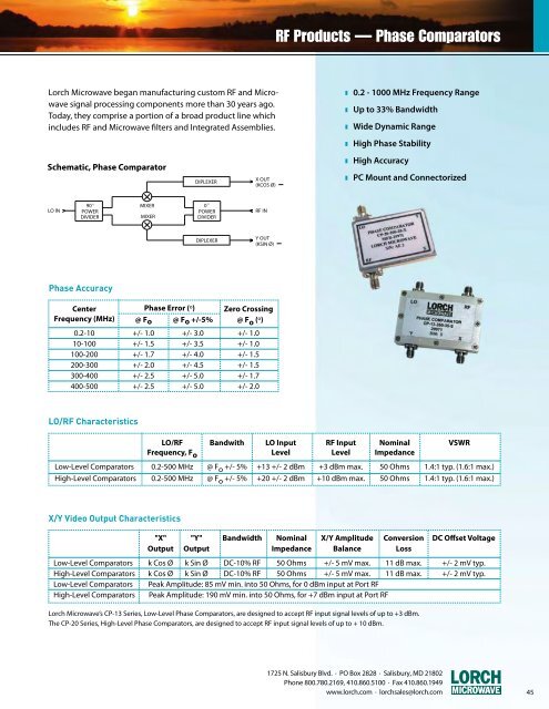
<strong>Lorch</strong> <strong>Microwave</strong> began manufacturing cus<strong>to</strong>m RF and <strong>Microwave</strong><br />
signal processing components more than 30 years ago.<br />
Today, they comprise a portion of a broad product line which<br />
includes RF and <strong>Microwave</strong> filters and Integrated Assemblies.<br />
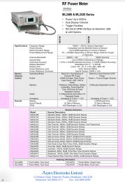
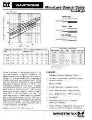
SCHEMATIC, PHASE COMPARATOR<br />
z 0.2 - 1000 MHz Frequency Range<br />
z Up <strong>to</strong> 33% Bandwidth<br />
z Wide Dynamic Range<br />
z High Phase Stability<br />
Schematic, Phase Compara<strong>to</strong>r<br />
DIPLEXER<br />
X OUT<br />
(KCOS Ø)<br />
z High Accuracy<br />
z PC Mount and Connec<strong>to</strong>rized<br />
LO IN<br />
90<br />
POWER<br />
DIVIDER<br />
MIXER<br />
O<br />
0<br />
MIXER<br />
O<br />
POWER<br />
DIVIDER<br />
RF IN<br />
DIPLEXER<br />
Y OUT<br />
(KSIN Ø)<br />
Phase Accuracy<br />
Center Phase Error (º) Zero Crossing<br />
Frequency (MHz) @ Fo @ Fo +/-5% @ F o (º)<br />
1<br />
0.2-10 +/- 1.0 +/- 3.0 +/- 1.0<br />
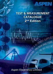
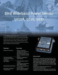
INPUT PHASE ANGLE vs OUTPUT VOLTAGE<br />
10-100 +/- 1.5 +/- 3.5 +/- 1.0<br />
100-200 +/- 1.7 +/- 4.0 +/- 1.5<br />
200-300 +/- 2.0 +/- 4.5 +/- 1.5<br />
300-400 +/- 2.5 +/- 5.0 +/- 1.7<br />
400-500 +/- 2.5 +/- 5.0 +/- 2.0<br />
LO/RF Characteristics<br />
0<br />
LO/RF Bandwith LO Input RF Input Nominal VSWR<br />
Frequency, F o Level Level Impedance<br />
Low-Level Compara<strong>to</strong>rs 0.2-500 MHz @ F o +/- 5% +13 +/- 2 dBm +3 dBm max. 50 Ohms 1.4:1 typ. (1.6:1 max.)<br />
-1<br />
High-Level Compara<strong>to</strong>rs 0.2-500 MHz @ F o +/- 5% +20 +/- 2 dBm +10 dBm max. 50 Ohms 1.4:1 typ. (1.6:1 max.)<br />
0 90 180 270 360<br />
X/Y Video Output Characteristics<br />
= X Output<br />
= Y Output<br />
"X" "Y" Bandwidth Nominal X/Y Amplitude Conversion DC Offset Voltage<br />
Output Output Impedance Balance Loss<br />
Low-Level Compara<strong>to</strong>rs k Cos Ø k Sin Ø DC-10% RF 50 Ohms +/- 5 mV max. 11 dB max. +/- 2 mV typ.<br />
High-Level Compara<strong>to</strong>rs k Cos Ø k Sin Ø DC-10% RF 50 Ohms +/- 5 mV max. 11 dB max. +/- 2 mV typ.<br />
Low-Level Compara<strong>to</strong>rs Peak Amplitude: 85 mV min. in<strong>to</strong> 50 Ohms, for 0 dBm input at Port RF<br />
High-Level Compara<strong>to</strong>rs Peak Amplitude: 190 mV min. in<strong>to</strong> 50 Ohms, for +7 dBm input at Port RF<br />
<strong>Lorch</strong> <strong>Microwave</strong>’s CP-13 Series, Low-Level Phase Compara<strong>to</strong>rs, are designed <strong>to</strong> accept RF input signal levels of up <strong>to</strong> +3 dBm.<br />
The CP-20 Series, High-Level Phase Compara<strong>to</strong>rs, are designed <strong>to</strong> accept RF input signal levels of up <strong>to</strong> + 10 dBm.<br />
1725 N. Salisbury Blvd. · PO Box 2828 · Salisbury, MD 21802<br />
Phone 800.780.2169, 410.860.5100 · Fax 410.860.1949<br />
www.lorch.com · lorchsales@lorch.com 45