bringing technology to life - Lorch Microwave
bringing technology to life - Lorch Microwave
bringing technology to life - Lorch Microwave

You also want an ePaper? Increase the reach of your titles
YUMPU automatically turns print PDFs into web optimized ePapers that Google loves.
inging <strong>technology</strong> <strong>to</strong> <strong>life</strong>
For four decades, <strong>Lorch</strong> <strong>Microwave</strong> has continuously supplied RF and <strong>Microwave</strong><br />
components and systems <strong>to</strong> the leading military, industrial, and commercial<br />
manufacturers worldwide. This his<strong>to</strong>ry is based on the fundamental principle<br />
that we supply solutions for the changing needs of our cus<strong>to</strong>mers. Through<br />
continuous investment in engineering and manufacturing capabilities, <strong>Lorch</strong> is<br />
able <strong>to</strong> respond <strong>to</strong> our cus<strong>to</strong>mer’s unique cus<strong>to</strong>m requirements as though we<br />
are supplying “standard off-the-shelf product.”<br />
<strong>Lorch</strong> <strong>Microwave</strong> is committed <strong>to</strong> providing our cus<strong>to</strong>mers with technically<br />
advanced, high quality products at competitive prices. As such, all products<br />
offered by <strong>Lorch</strong> <strong>Microwave</strong> are subject <strong>to</strong> the same rigorous design, manufacturing<br />
and inspection criteria. Manufacturing, testing and inspection facilities<br />
are located in our modern 37,000 square foot fac<strong>to</strong>ry in Salisbury, Maryland.<br />
The company is MIL qualified and conforms <strong>to</strong> the principals set forth in<br />
ISO-9001 and ISO-14001. Regardless of application, the processes and procedures<br />
followed at <strong>Lorch</strong> help ensure that all products are fully compliant <strong>to</strong> all<br />
specifications and will perform as designed right out of the box.<br />
The products described in this catalog have resulted from a combination of 40<br />
years of design experience as well as the utilization of the latest computer aided<br />
design <strong>technology</strong> and manufacturing techniques. Further, <strong>Lorch</strong>’s research<br />
and development activities are constantly evaluating new materials, plating<br />
techniques, and manufacturing processes <strong>to</strong> ensure that the company offers the<br />
highest performing components available <strong>to</strong>day.<br />
<strong>Lorch</strong> <strong>Microwave</strong>’s designs are developed for ease of manufacturing and flexibility<br />
as a prime consideration. This, coupled with adequate inven<strong>to</strong>ries of raw<br />
materials and inven<strong>to</strong>ries of raw materials and in-house control of all critical<br />
process from design through manufacturing and testing yields deliveries that<br />
are quoted in weeks rather than months.<br />
At <strong>Lorch</strong> <strong>Microwave</strong>, we believe that putting our trademark on the product is<br />
our commitment <strong>to</strong> you of quality, service and satisfaction. We understand that<br />
our product includes not just the component or system purchase, but rather,<br />
the entire purchasing experience. You have our commitment that <strong>Lorch</strong> will<br />
continue our tradition of unparalleled service <strong>to</strong> the microwave industry.<br />
1725 N. Salisbury Blvd. · PO Box 2828 · Salisbury, MD 21802<br />
Phone 800.780.2169, 410.860.5100 · Fax 410.860.1949<br />
www.lorch.com · lorchsales@lorch.com 3
Part numbers are assigned at time of order. If you<br />
have generated a part number, give the name of the<br />
component and the frequency range as stated in the<br />
catalog. If special options or non-standard features are<br />
desired, they should be fully described and a unique<br />
part number will be assigned. Special modifications<br />
for unusual applications, cus<strong>to</strong>m components and<br />
adaptation of existing parts can be designed and<br />
developed by our engineering department. A qualified<br />
staff of experienced sales and design engineers is<br />
available <strong>to</strong> assist you in specifying components for<br />
your special requirements.<br />
Ordering Address<br />
<strong>Lorch</strong> <strong>Microwave</strong><br />
PO Box 2828<br />
Salisbury, MD 21802<br />
Ordering: 800-780-2169<br />
Phone: 410-860-5100<br />
Fax: 410-860-1949<br />
Our CAGE code is 29971<br />
Orders may be placed through our local sales<br />
representative in your area or directly with the fac<strong>to</strong>ry.<br />
Final determination of price, terms, conditions, and<br />
acceptance of orders, however, may be made only by our<br />
staff in Salisbury, Maryland.<br />
Payment Options<br />
<strong>Lorch</strong> <strong>Microwave</strong> offers many convenient payment<br />
methods, including: Open Account (subject <strong>to</strong> credit<br />
approval), Mastercard/Visa, and Letters of Credit.<br />
Please specify payment method at time of order.<br />
Delivery<br />
If a carrier is not specified at the time of order, shipment<br />
will be made via UPS Ground or UPS Air depending<br />
on distance from the fac<strong>to</strong>ry. For rush service, we will<br />
ship by air freight, air express, or others, as requested.<br />
Firm delivery dates are given at time of quotation. <strong>Lorch</strong><br />
<strong>Microwave</strong> maintains complete inven<strong>to</strong>ry so that many<br />
items may be delivered within 24 hours when quoted<br />
by the fac<strong>to</strong>ry.<br />
Packing and Packaging<br />
Packing and Packaging is normally supplied <strong>to</strong> “Best<br />
Commercial” standards. Packaging <strong>to</strong> military requirements,<br />
including Bar Coding is available on request.<br />
Warranty<br />
Products manufactured by <strong>Lorch</strong> <strong>Microwave</strong> are warrantied<br />
against defective materials and workmanship for<br />
a period of one year from the date of shipment. <strong>Lorch</strong><br />
<strong>Microwave</strong>’s obligation for any defect shall be limited<br />
<strong>to</strong> the repair of the defective part. <strong>Lorch</strong> <strong>Microwave</strong><br />
assumes no liability if defects result from improper use,<br />
operation above rated capacities, repairs not made by<br />
us, or misapplication of equipment. No other warranty<br />
is expressed or implied. <strong>Lorch</strong> <strong>Microwave</strong> neither makes<br />
nor authorizes any other person <strong>to</strong> make any other<br />
warranty concerning its products. <strong>Lorch</strong> <strong>Microwave</strong> is<br />
not liable for consequential damages. Warranty returns<br />
must first be authorized by our sales office prior <strong>to</strong><br />
return and must be returned pre-paid.<br />
Terms and Conditions<br />
Please visit our website at www.lorch.com/terms for<br />
a complete listing.<br />
4<br />
1725 N. Salisbury Blvd. · PO Box 2828 · Salisbury, MD 21802<br />
Phone 800.780.2169, 410.860.5100 · Fax 410.860.1949<br />
www.lorch.com · lorchsales@lorch.com
General Company Information<br />
3 Company Introduction<br />
4 Ordering Information<br />
5 Contents<br />
Ceramic Filters<br />
27 General Information<br />
28 Specifying Ceramic Filters<br />
29 Ceramic Outline Drawings<br />
30 Z-Pack Series<br />
Filter Products<br />
6 General Filter Information<br />
7-8 Filter Circuit Topology<br />
9 Environmental Capabilities<br />
Cavity Filters<br />
10-11 General Information<br />
12-13 Specifying Cavity Filters<br />
14-16 Cavity Outline Drawings<br />
17 Waveguide General<br />
Discrete Components<br />
18 General Information<br />
19 Specifying Bandpass Filters<br />
20 Specifying Lowpass Filters<br />
21 Specifying Highpass Filters<br />
22-26 Outline Drawings<br />
Integrated Assemblies 31-35<br />
Tunable Filters<br />
36-37 Tunable Bandpass Filters<br />
38 Tunable Bandreject Filters<br />
39 Digital Tunable Filters<br />
Tubular Filters<br />
40 General Information<br />
41 Specifying Bandpass Filters<br />
42 Specifying Lowpass Filters<br />
43-44 Tubular Filter Dimensions<br />
RF Products<br />
45 Phase Compara<strong>to</strong>rs<br />
46 Manual Phase Shifters<br />
47 Digital Phase Shifters<br />
48 Voltage Controlled Phase Shifters<br />
49 Voltage Controlled Attenua<strong>to</strong>rs<br />
50 Broad Band Mixers<br />
1725 N. Salisbury Blvd. · PO Box 2828 · Salisbury, MD 21802<br />
Phone 800.780.2169, 410.860.5100 · Fax 410.860.1949<br />
www.lorch.com · lorchsales@lorch.com 5
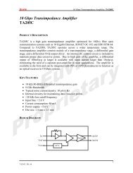
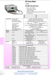
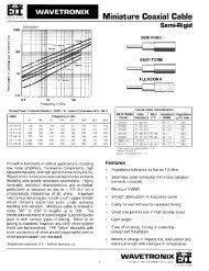
0.5 dB Relative Bandwidth<br />
4.5<br />
4.0<br />
N = 4 - 10<br />
In many cases it is important <strong>to</strong> know more about the passband<br />
of a filter around the transition region between the passband<br />
and the s<strong>to</strong>pband. The information provided serves as a design<br />
aid where passband flatness is an important criteria.<br />
Insertion Loss (dB)<br />
3.5<br />
3.0<br />
2.5<br />
2.0<br />
1.5<br />
N = 2<br />
N = 3<br />
The dissipative losses are greater at the bandedges than at<br />
center frequency. The passband of the filter becomes rounded<br />
at the bandedges. Since both the dissipative loss and the<br />
reflective losses are present in each filter, the ripple becomes<br />
superimposed on the rounded passband created by the dissipative<br />
losses. Because of this it is more useful <strong>to</strong> specify a relative<br />
bandwidth as shown than the equi-ripple bandwidth.<br />
The relationship between center frequency insertion loss and the<br />
+/- 5 degree phase linearity bandwidth is shown. This bandwidth<br />
is defined as the maximum deviation from a best-fit line drawn<br />
between two points on either side of the passband.<br />
The relationship between center frequency insertion loss and<br />
the 1.5:1 VSWR bandwidth is also given. The VSWR corresponds<br />
<strong>to</strong> a 14 dB Return Loss in a 50 Ohm system.<br />
Example:<br />
A 4 pole filter with a 3 dB bandwidth of 60 MHz and<br />
3.5 dB insertion loss:<br />
0.5 dB bandwidth is .64 x 60 = 38.4 MHz<br />
1.0 dB bandwidth is .77 x 60 = 46.2 MHz<br />
+/- 5° phase bandwidth is .62 x 60 = 37.2 MHz<br />
1.5:1 VSWR bandwidth is .85 x 60 = 51 MHz<br />
Note: When out-of-band attenuation is not specified, a 3 dB<br />
bandwidth <strong>to</strong>lerance of -0 / + 10% nominal will be used.<br />
The (%) <strong>to</strong>lerance on bandwidth will be inversely proportional<br />
<strong>to</strong> an actual decrease in bandwidth (MHz) vs. frequency. If a<br />
maximum bandwidth is required, please specify.<br />
Insertion Loss (dB)<br />
Insertion Loss (dB)<br />
1.0<br />
0.5<br />
0.2 0.3 0.4 0.5 0.6 0.7 0.8 0.9 1.0<br />
4.5<br />
4.0<br />
3.5<br />
3.0<br />
2.5<br />
2.0<br />
1.5<br />
1.0<br />
Fractional Bandwidth<br />
N = 2<br />
N = 3<br />
N = 4 - 10<br />
0.5<br />
0.2 0.3 0.4 0.5 0.6 0.7 0.8 0.9 1.0<br />
4.5<br />
4.0<br />
3.5<br />
3.0<br />
2.5<br />
2.0<br />
1.5<br />
1.0<br />
1.0 dB Relative Bandwidth<br />
Fractional Bandwidth<br />
± 5° Relative Phase Bandwidth<br />
N = 2<br />
N = 4 - 10<br />
N = 3<br />
0.5<br />
0.1 0.2 0.3 0.4 0.5 0.6 0.7 0.8 0.9<br />
1.5:1 VSWR Bandwidth Fractional p4 Bandwidth<br />
Insertion Loss<br />
Ripple<br />
0 dB Relative BW<br />
1.5:1 VSWR Bandwidth<br />
4.5<br />
0.5 dB Relative BW<br />
4.0<br />
N = 2<br />
N = 6 - 10<br />
1.0 dB Relative BW<br />
3.0 dB Relative BW<br />
Insertion Loss (dB)<br />
3.5<br />
3.0<br />
2.5<br />
2.0<br />
1.5<br />
N = 3<br />
N = 4<br />
N = 5<br />
1.0<br />
6<br />
1725 N. Salisbury Blvd. · PO Box 2828 · Salisbury, MD 21802<br />
Phone 800.780.2169, 410.860.5100 · Fax 410.860.1949<br />
www.lorch.com · lorchsales@lorch.com<br />
0.5<br />
0.5 0.6 0.7 0.8 0.9 1.0 1.1 1.2 1.3<br />
Fractional Bandwidth
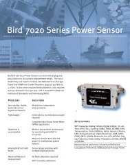
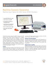
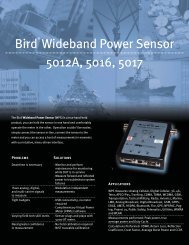
Modern filter synthesis allows the placement of transmission zeroes by the designer. <strong>Lorch</strong> <strong>Microwave</strong> incorporates the<br />
use of the latest software <strong>to</strong> design our filters <strong>to</strong> each unique application. Filters may be designed with asymmetrical<br />
responses <strong>to</strong> most efficiently attenuate low side or high side signals. Highpass Symmetrical Filter p,4 responses are used where both lower<br />
and upper attenuations are important. <strong>Lorch</strong> <strong>Microwave</strong> utilizes elliptic or pole-placed functions where finite zeros are<br />
required. The schematics and response curves below show just a few of the filter networks used.<br />
< Increasing Attenuation<br />
< Increasing Attenuation<br />
Increasing Frequency ><br />
Lowpass Filter<br />
This is the simplest form of a ladder network. The<br />
lowpass filter response extends from D.C. <strong>to</strong> a specified<br />
Lowpass/Highpass<br />
cu<strong>to</strong>ff frequency.<br />
Filter<br />
The passband insertion loss is measured<br />
at .90 times the 3 dB cu<strong>to</strong>ff. S<strong>to</strong>pband response<br />
may extend <strong>to</strong> 100 times the cu<strong>to</strong>ff frequency.<br />
Increasing Frequency ><br />
Hipass Filter<br />
This is the inverse of the lowpass circuit shown. The<br />
highpass filter is Direct specified Scaled with Bandpass a 3 dB cu<strong>to</strong>ff Filteras well as<br />
an upper passband limit. Because of parasitic elements<br />
inherent in the design, the passband cannot extend<br />
<strong>to</strong> infinite frequencies. Responses are available <strong>to</strong> 20<br />
times the specified cu<strong>to</strong>ff frequency.<br />
< Increasing Attenuation<br />
< Increasing Attenuation<br />
Increasing Frequency ><br />
Lowpass/Highpass Filter<br />
This is a cascade of the lowpass and highpass circuits<br />
shown above. This configuration is generally used for<br />
bandwidths of an octave or greater. The response may<br />
be tailored <strong>to</strong> meet the upper and lower s<strong>to</strong>pband<br />
requirements as needed.<br />
Increasing Frequency ><br />
Direct Scaled Bandpass Filters<br />
This is the classical “resonant ladder” used in wideband<br />
applications. The circuit is obtained by a lowpass <strong>to</strong><br />
bandpass transform. Its advantages are geometric<br />
symmetry and a small spread of element values when<br />
used in circuit transforms.<br />
1725 N. Salisbury Blvd. · PO Box 2828 · Salisbury, MD 21802<br />
Phone 800.780.2169, 410.860.5100 · Fax 410.860.1949<br />
www.lorch.com · lorchsales@lorch.com 7
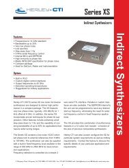
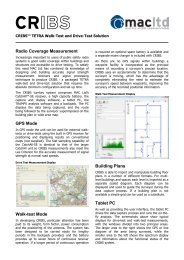
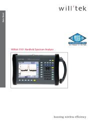
Nodal Circuit Bandpass Filter<br />
Mesh Circuit Bandpass Filter<br />
< Increasing Attenuation<br />
< Increasing Attenuation<br />
Increasing Frequency ><br />
Nodal Circuit Bandpass Filters<br />
The capacitively coupled nodal circuit<br />
provides an excellent configuration for<br />
narrowband use. The highside response<br />
may be sharpened by the use of a variety<br />
of transforming networks.<br />
Elliptic Filter<br />
Increasing Frequency ><br />
Mesh Circuit Bandpass Filter<br />
This is the “dual” of the nodal circuit shown.<br />
It provides a steeper high side response due<br />
<strong>to</strong> the greater number of zeroes at infinity. This<br />
circuit may also use a variety of transforming<br />
networks <strong>to</strong> provide symmetry <strong>to</strong> the response.<br />
Pole Placed Filter<br />
< Increasing Attenuation<br />
< Increasing Attenuation<br />
Increasing Frequency ><br />
Elliptic Filter<br />
The Elliptic filter (also known as a Cauer<br />
response) provides the steepest out of band<br />
attenuation of any filter response. This is<br />
achieved by adding anti-resonance, or notch<br />
sections <strong>to</strong> the filter. These responses are<br />
available in Lowpass, Highpass, Bandpass<br />
and Bands<strong>to</strong>p.<br />
Increasing Frequency ><br />
Pole Placed Filter<br />
Unlike the Elliptic filter where the finite<br />
attenuation poles are determined by the<br />
mathematical function, the Pole Placed filter<br />
allows the designer <strong>to</strong> specify where these<br />
points fall. This design is useful where there<br />
are specific single frequencies <strong>to</strong> remove.<br />
8<br />
1725 N. Salisbury Blvd. · PO Box 2828 · Salisbury, MD 21802<br />
Phone 800.780.2169, 410.860.5100 · Fax 410.860.1949<br />
www.lorch.com · lorchsales@lorch.com
The standard environmental<br />
conditions are listed throughout<br />
the catalog in the corresponding<br />
section for each product series.<br />
Most products offered by <strong>Lorch</strong><br />
<strong>Microwave</strong> may be designed <strong>to</strong> meet<br />
any of the extended environmental<br />
specifications shown in the following<br />
table. Conditions not listed may also<br />
be acceptable. <strong>Lorch</strong> <strong>Microwave</strong> has<br />
the capability <strong>to</strong> test our products<br />
in accordance with these or similar<br />
environmental test methods. Please<br />
contact the sales department for<br />
your specific requirements.<br />
Rating or Test<br />
MIL-STD-202F<br />
Method/Conditions<br />
Temperature Operating, °C<br />
Temperature S<strong>to</strong>rage, °C<br />
Gross Leak<br />
Fine Leak<br />
Moisture Resistance (Humidity)<br />
Thermal Shock<br />
Mechanical Shock<br />
Random Vibration<br />
Vibration High Frequency<br />
Solderability<br />
Terminal Strength and Fatigue<br />
Altitude<br />
Salt Spray<br />
Solvent Resistance<br />
Solder Heat<br />
-55 °C, +85 °C<br />
-55 °C, +125 °C<br />
Method 112<br />
Method 112<br />
Method 106<br />
Method 107<br />
Method 213<br />
Method 214<br />
Method 204<br />
Method 208<br />
Method 211<br />
Method 105<br />
Method 101<br />
Method 215<br />
Method 210<br />
1725 N. Salisbury Blvd. · PO Box 2828 · Salisbury, MD 21802<br />
Phone 800.780.2169, 410.860.5100 · Fax 410.860.1949<br />
www.lorch.com · lorchsales@lorch.com 9
z 30 MHz <strong>to</strong> 40 GHz<br />
z 3 dB Bandwidths from 66%<br />
z High “Q”, Low Loss<br />
z High Power<br />
z Computer-Aided Designs<br />
z Helical, Combline, Interdigital<br />
z Waveguide<br />
z 12 S<strong>to</strong>ck Series<br />
<strong>Lorch</strong> <strong>Microwave</strong>'s cavity filter designs are available in the<br />
frequency range of 30 MHz <strong>to</strong> 40 GHz and with bandwidth<br />
options from less than 0.5% <strong>to</strong> over 66%. Cavity filters offer<br />
the user very low insertion loss, steep skirt selectivity, and<br />
narrower bandwidths than discrete component filters. Cavity<br />
filter performance is based on parts selection and physical<br />
layout of the helical coils, resona<strong>to</strong>rs, as well as the shape<br />
and size of the cavity housing. <strong>Lorch</strong> <strong>Microwave</strong> offers the<br />
user 12 unique s<strong>to</strong>ck designs <strong>to</strong> satisfy the majority of applications.<br />
At lower frequencies a helical coil is used <strong>to</strong> excite<br />
the electromagnetic field, while a 1/8 <strong>to</strong> 1/4 wave capacitively<br />
loaded design is used at higher frequencies. A cylindrical<br />
waveguide design is used <strong>to</strong> achieve narrow bandwidths<br />
and high power operation.<br />
Each filter is cus<strong>to</strong>m designed <strong>to</strong> your exact specification<br />
so that you will receive the optimum performance at the<br />
lowest cost. Filter performance is easily predicted using our<br />
proprietary software, while CAD files are generated for our<br />
CNC machine and fabrication center. At <strong>Lorch</strong> <strong>Microwave</strong>,<br />
even complex designs and working drawings can be generated<br />
in a matter of a few hours…not weeks.<br />
Standard cavity filters generally are designed using aluminum<br />
as the base metal. As most raw metals are inherently<br />
lossy, filter housings are silver plated for improved electrical<br />
characteristics and current flow. Brass, copper, aluminum<br />
or bi-metal resona<strong>to</strong>rs are used <strong>to</strong> minimize frequency drift<br />
over temperature.<br />
10<br />
1725 N. Salisbury Blvd. · PO Box 2828 · Salisbury, MD 21802<br />
Phone 800.780.2169, 410.860.5100 · Fax 410.860.1949<br />
www.lorch.com · lorchsales@lorch.com
The tables, graphs and curves on the following pages have<br />
been prepared <strong>to</strong> enable you <strong>to</strong> determine an approximation<br />
of the electrical performance and physical size you<br />
can expect. If by chance your requirements cannot be<br />
met from the units described herein, please contact our<br />
technical marketing staff for assistance. With over 30 years<br />
of filter designs in our data bank, chances are good that we<br />
have successfully solved a similar problem in the past.<br />
Narrowband - 0.5% <strong>to</strong> 4%<br />
P/N Frequency % 3 dB VSWR Number Avg. Power Operating Relative<br />
(MHz) Bandwidth (Typical) of Sections (Watts) Temp. (°C) Humidity<br />
CP 30 - 2000 0.5 - 4 1.5:1 2 - 6 10 -55 <strong>to</strong> +85 95%<br />
CF2 500 - 2000 0.5 - 4 1.5:1 2 - 8 10 -55 <strong>to</strong> +85 95%<br />
CF3 500 - 2500 0.5 - 4 1.5:1 2 - 8 10 -55 <strong>to</strong> +85 95%<br />
CF4 2000 - 3000 0.5 - 4 1.5:1 2 - 8 10 -55 <strong>to</strong> +85 95%<br />
CF6 2000 - 8000 0.5 - 4 1.5:1 2 - 8 10 -55 <strong>to</strong> +85 95%<br />
CF7 4000 - 26000 0.5 - 4 1.5:1 2 - 8 10 -55 <strong>to</strong> +85 95%<br />
Narrowband (Combline) - 1% <strong>to</strong> 25%<br />
P/N Frequency % 3 dB VSWR Number Avg. Power Operating Relative<br />
(MHz) Bandwidth (Typical) of Sections (Watts) Temp. (°C) Humidity<br />
EZ3 500 - 6000 1 - 25 1.5:1 2 - 17 10 -55 <strong>to</strong> +85 95%<br />
EZ4 1000 - 8000 1 - 25 1.5:1 2 - 17 10 -55 <strong>to</strong> +85 95%<br />
EZ5 2000 - 12000 1 - 25 1.5:1 2 - 17 10 -55 <strong>to</strong> +85 95%<br />
EZ6 4000 - 18000 1 - 25 1.5:1 2 - 17 10 -55 <strong>to</strong> +85 95%<br />
EZ7 6000 - 26000 1 - 25 1.5:1 2 - 17 10 -55 <strong>to</strong> +85 95%<br />
Wideband (Interdigital) -25% <strong>to</strong> 66%<br />
P/N Frequency % 3 dB VSWR Number Avg. Power Operating Relative<br />
(MHz) Bandwidth (Typical) of Sections (Watts) Temp. (°C) Humidity<br />
IZ3 500 - 6000 25 - 66 2.0:1 2 - 17 10 -55 <strong>to</strong> +85 95%<br />
IZ4 1000 - 8000 25 - 66 2.0:1 2 - 17 10 -55 <strong>to</strong> +85 95%<br />
IZ5 2000 - 12000 25 - 66 2.0:1 2 - 17 10 -55 <strong>to</strong> +85 95%<br />
IZ6 4000 - 18000 25 - 66 2.0:1 2 - 17 10 -55 <strong>to</strong> +85 95%<br />
IZ7 6000 - 26000 25 - 66 2.0:1 2 - 17 10 -55 <strong>to</strong> +85 95%<br />
Shock 10G<br />
Vibration 20G<br />
See pages 12-14 for mechanical outlines and dimensions.<br />
Contact fac<strong>to</strong>ry for specific requirements not listed above.<br />
1725 N. Salisbury Blvd. · PO Box 2828 · Salisbury, MD 21802<br />
Phone 800.780.2169, 410.860.5100 · Fax 410.860.1949<br />
www.lorch.com · lorchsales@lorch.com 11
Cavity Filter Part Number Description<br />
4 CF2 - 1200 / A15 - S / SM<br />
1 2 3 4 5 6<br />
1. Number of Sections<br />
2. Series and Package Size<br />
3. Center Frequency, MHz<br />
4. Bandwidth and Code<br />
(3 dB BW Standard)<br />
5. Input Connec<strong>to</strong>r<br />
6. Output Connec<strong>to</strong>r<br />
(if different from input)<br />
Bandwidth<br />
3 dB<br />
1 dB<br />
equi-ripple<br />
special<br />
Connec<strong>to</strong>rs<br />
Connec<strong>to</strong>r Type<br />
BNC Female (1)<br />
BNC Male (1)<br />
Blind Mate<br />
N Female (1)<br />
N Male (1)<br />
RF Pin (2)<br />
SMA Female<br />
SMA Male<br />
SMA Removable<br />
Special<br />
TNC Female (1)<br />
TNC Male (1)<br />
Designa<strong>to</strong>r<br />
/(blank)<br />
/A<br />
/R<br />
/X<br />
Designa<strong>to</strong>r<br />
B<br />
BM<br />
BP<br />
N<br />
NM<br />
P<br />
S<br />
SM<br />
SR<br />
X<br />
T<br />
TM<br />
Calculating Number of Sections<br />
The following curves show the s<strong>to</strong>pband frequencies<br />
normalized <strong>to</strong> the 3 dB bandwidth for filters with 2 <strong>to</strong> 13<br />
sections. A ratio of s<strong>to</strong>pband frequency <strong>to</strong> 3 dB bandwidth<br />
is used.<br />
The curve on the next page shows a slightly asymmetric<br />
frequency response resulting from the circuit used. Other<br />
schematics may be utilized <strong>to</strong> yield different attenuation<br />
characteristics (i.e. steeper on the high frequency side of<br />
the passband and shallower on the low side).<br />
Example:<br />
A CF-Series filter has a center frequency of 1000 MHz and a<br />
3 dB bandwidth of 10 MHz. A s<strong>to</strong>pband attenuation of 60 dB<br />
is required at 980 MHz and 1030 MHz.<br />
The percentage bandwidth is 1%, calculated as follows:<br />
3 dB BW (MHz) x 100 =<br />
Fo (MHz)<br />
10<br />
x 100 = 1%<br />
1000<br />
For the first s<strong>to</strong>pband requirement: Number of 3 dB<br />
bandwidths from center frequency = (1000 - 980) = 2.0<br />
10<br />
From the CP/CF series attenuation curve, we find that a<br />
minimum of 7 sections are required.<br />
The second s<strong>to</strong>pband requirement is: Number of 3 dB<br />
bandwidths from center frequency = (1030 - 1000) = 3.0<br />
10<br />
From the CP/CF series attenuation curve, we find that 5<br />
sections minimum are required.<br />
The greater number of sections must always be used <strong>to</strong><br />
insure full specification compliance; therefore, a 7 section<br />
should be used.<br />
(1) Requires Minimum Cross Section of 0.88”<br />
(2) Requires SMA Removable Connec<strong>to</strong>rs at<br />
High Frequencies<br />
12<br />
1725 N. Salisbury Blvd. · PO Box 2828 · Salisbury, MD 21802<br />
Phone 800.780.2169, 410.860.5100 · Fax 410.860.1949<br />
www.lorch.com · lorchsales@lorch.com
Insertion Loss Calculation<br />
Knowing the number of sections, center frequency and<br />
bandwidth of the filter, insertion loss may be calculated<br />
using the following formula:<br />
Loss =<br />
N - 1.5<br />
Q x %3dB BW<br />
+ 0.2<br />
Example: 5CF2-915/25-N<br />
1. Percentage BW = 25 / 915 x 100 = 2.7%<br />
2. Q from CF series curves = 2.9<br />
3. Number of Sections = 5<br />
4.<br />
5 - 1.5<br />
Loss =<br />
+ 0.2<br />
2.9 x 2.7<br />
Attenuation dB<br />
5<br />
4<br />
3<br />
2<br />
1<br />
0.5<br />
“Q”-CF, CP Series, Narrowband Cavities<br />
CF2<br />
CF3<br />
CF4<br />
CP<br />
0.3<br />
0.1 0.5 1.0 5.0 10.0 30.0<br />
Center Frequency (GHz)<br />
CF6<br />
CF7<br />
CF7<br />
Example: 9EZ6-8725/1375-S<br />
1. Percentage BW = 1375/8725 x 100 = 15.8%<br />
2. Q from EZ series curves = 1.1<br />
3. Number of Sections = 9<br />
4.<br />
Loss =<br />
9 - 1.5<br />
+ 0.2 = 0.63 dB<br />
1.1 x 15.8<br />
Attenuation dB<br />
3.0<br />
2.0<br />
1.0<br />
“Q”-EZ, IZ Series, Wideband Cavities<br />
EZ3<br />
EZ4<br />
EZ5<br />
EZ6<br />
EZ7<br />
0.6<br />
0.5 1.0 2.0 3.0 5.0 10.0 20.0 30.0<br />
Center Frequency (GHz)<br />
0<br />
CP and CF Series Attenuation Characteristics<br />
3dB Ref BW<br />
0<br />
EZ and IZ Series Attenuation Characteristics<br />
3dB Ref BW<br />
10<br />
10<br />
N = 3<br />
N = 3<br />
Attenuation dB<br />
20<br />
30<br />
40<br />
50<br />
N = 2<br />
N = 3<br />
N = 4<br />
N = 5<br />
N = 4<br />
N = 2<br />
N = 3<br />
Attenuation dB<br />
20<br />
30<br />
40<br />
50<br />
N = 5<br />
N = 7<br />
N = 11<br />
N = 11<br />
N = 5<br />
N = 7<br />
60<br />
N = 7<br />
70<br />
-4 -3 -2 -1 1 2 3 4<br />
N = 7<br />
N = 5<br />
Number of 3 dB Bandwidths<br />
From Center Frequency<br />
60<br />
N = 13<br />
N = 13<br />
70<br />
N = 9 N = 9<br />
-4 -3 -2 -1 1 2 3 4<br />
Number of 3 dB Bandwidths<br />
From Center Frequency<br />
1725 N. Salisbury Blvd. · PO Box 2828 · Salisbury, MD 21802<br />
Phone 800.780.2169, 410.860.5100 · Fax 410.860.1949<br />
www.lorch.com · lorchsales@lorch.com 13
CP, BRP Series<br />
L<br />
CF2 Series<br />
L<br />
H<br />
H<br />
.13 (3.3)<br />
.19 (4.8)<br />
.160 (4.1) Dia. 4 places<br />
.06 (1.5)<br />
.38 (9.7)<br />
.13 (3.3)<br />
.15 (3.81) .190 (4.8) Dia. 4 places<br />
.38 (9.7)<br />
.19 (4.8)<br />
.75 (19.1)<br />
1.0<br />
(25.4)<br />
1.13<br />
(28.7)<br />
1.62<br />
(41.2)<br />
2.00<br />
(50.8)<br />
.13 (3.3)<br />
CP Series<br />
Frequency Width Height Length vs. Number of Sections — Inches (mm)<br />
(MHz) Inches (mm) Inches (mm) 2 3 4 5 6<br />
30 - 50 1.13 (28.7) 3.88 (98.6) 2.50 (63.5) 3.63 (92.2) 4.75 (120.7) 5.88 (149.4) 7.00 (177.8)<br />
51 - 65 1.13 (28.7) 2.88 (73.2) 2.50 (63.5) 3.63 (92.2) 4.75 (120.7) 5.88 (149.4) 7.00 (177.8)<br />
66 - 100 1.13 (28.7) 2.38 (60.5) 2.50 (63.5) 3.63 (92.2) 4.75 (120.7) 5.88 (149.4) 7.00 (177.8)<br />
101 - 500 1.13 (28.7) 1.88 (47.8) 2.50 (63.5) 3.63 (92.2) 4.75 (120.7) 5.88 (149.4) 7.00 (177.8)<br />
501 - 600 1.13 (28.7) 4.88 (124.0) 2.50 (63.5) 3.63 (92.2) 4.75 (120.7) 5.88 (149.4) 7.00 (177.8)<br />
601 - 900 1.13 (28.7) 3.88 (98.6) 2.50 (63.5) 3.63 (92.2) 4.75 (120.7) 5.88 (149.4) 7.00 (177.8)<br />
901 - 1300 1.13 (28.7) 2.88 (73.2) 2.50 (63.5) 3.63 (92.2) 4.75 (120.7) 5.88 (149.4) 7.00 (177.8)<br />
1301 - 1800 1.13 (28.7) 2.38 (60.5) 2.50 (63.5) 3.63 (92.2) 4.75 (120.7) 5.88 (149.4) 7.00 (177.8)<br />
1801 - 2000 1.13 (28.7) 1.88 (47.8) 2.50 (63.5) 3.63 (92.2) 4.75 (120.7) 5.88 (149.4) 7.00 (177.8)<br />
BRH Series<br />
Frequency Width Height Length vs. Number of Sections — Inches (mm)<br />
(MHz) Inches (mm) Inches (mm) 2 3 4 5 6<br />
30 - 50 1.13 (28.7) 4.88 (124.0) 2.50 (63.5) 3.63 (92.2) 4.75 (120.7) 5.88 (149.4 ) 7.00 (177.8)<br />
51 - 65 1.13 (28.7) 3.88 (98.6) 2.50 (63.5) 3.63 (92.2) 4.75 (120.7) 5.88 (149.4 ) 7.00 (177.8)<br />
66 - 100 1.13 (28.7) 3.38 (85.9) 2.50 (63.5) 3.63 (92.2) 4.75 (120.7) 5.88 (149.4 ) 7.00 (177.8)<br />
101 - 500 1.13 (28.7) 2.88 (73.2) 2.50 (63.5) 3.63 (92.2) 4.75 (120.7) 5.88 (149.4 ) 7.00 (177.8)<br />
501 - 600 1.13 (28.7) 5.88 (149.4) 2.50 (63.5) 3.63 (92.2) 4.75 (120.7) 5.88 (149.4 ) 7.00 (177.8)<br />
601 - 900 1.13 (28.7) 4.88 (124.0) 2.50 (63.5) 3.63 (92.2) 4.75 (120.7) 5.88 (149.4 ) 7.00 (177.8)<br />
CF2 Series<br />
Frequency Width Height Length vs. Number of Sections — Inches (mm)<br />
(MHz) Inches (mm) Inches (mm) 2 3 4 5 6<br />
500 - 750 2.0 (50.8) 6.6 (167.6) 3.9 (99.1) 5.7 (145) 7.6 (193.1) 9.4 (238.8) 11.2 (285)<br />
751 - 1000 2.0 (50.8) 4.6 (116.8) 3.9 (99.1) 5.7 (145) 7.6 (193.1) 9.4 (238.8) 11.2 (285)<br />
1001 - 1500 2.0 (50.8) 3.7 (94.0) 3.9 (99.1) 5.7 (145) 7.6 (193.1) 9.4 (238.8) 11.2 (285)<br />
1501 - 2000 2.0 (50.8) 2.7 (68.6) 3.9 (99.1) 5.7 (145) 7.6 (193.1) 9.4 (238.8) 11.2 (285)<br />
All dimensions are approximate. Contact fac<strong>to</strong>ry for actual sizes. All length dimensions are excluding connec<strong>to</strong>rs.<br />
14<br />
1725 N. Salisbury Blvd. · PO Box 2828 · Salisbury, MD 21802<br />
Phone 800.780.2169, 410.860.5100 · Fax 410.860.1949<br />
www.lorch.com · lorchsales@lorch.com
p19, CF4 Series<br />
CF3 Series<br />
L<br />
CF4 Series<br />
H<br />
H<br />
.13 (3.3)<br />
.38 (9.7)<br />
.13 (3.3)<br />
.15 (3.8)<br />
1.37<br />
(34.8)<br />
.160 (4.1) Dia. 4 places<br />
.38 (9.7)<br />
.19 (4.8)<br />
1.75<br />
(44.5)<br />
.15 (3.81)<br />
.62<br />
(15.75)<br />
.160 (4.1) Dia. 4 places<br />
.19 (4.83)<br />
1.0<br />
(25.4)<br />
CF3 Series<br />
Frequency Width Height Length vs. Number of Sections — Inches (mm)<br />
(MHz) Inches (mm) Inches (mm) 2 3 4 5 6<br />
500 - 750 1.75 (44.45) 6.6 (167.6) 3.00 (76.2) 4.3 (109.5) 5.6 (142.25) 6.9 (175.26) 8.3 (210.82)<br />
751 - 1000 1.75 (44.45) 4.6 (116.8) 3.00 (76.2) 4.3 (109.5) 5.6 (142.25) 6.9 (175.26) 8.3 (210.82)<br />
1001 - 1500 1.75 (44.45) 3.7 (94.0) 3.00 (76.2) 4.3 (109.5) 5.6 (142.25) 6.9 (175.26) 8.3 (210.82)<br />
1501 - 2000 1.75 (44.45) 2.7 (68.6) 3.00 (76.2) 4.3 (109.5) 5.6 (142.25) 6.9 (175.26) 8.3 (210.82)<br />
CF4 Series<br />
Frequency Width Height Length vs. Number of Sections — Inches (mm)<br />
(MHz) Inches (mm) Inches (mm) 2 3 4 5 6<br />
2001-3000 1.0 (25.4) 2.1 (53.4) 2.00 (50.8) 2.80 (71.1) 3.60 (91.4) 4.40 (111.8) 5.20 (132.1)<br />
CF6 Series<br />
L<br />
CF7 Series<br />
L<br />
H<br />
H<br />
.07 TYP.<br />
4X<br />
2-56 UNC - 2B<br />
.06 (1.5)<br />
2-56 UNC 2B 2 places<br />
.70<br />
.50<br />
(12.7)<br />
.07 TYP.<br />
CF6 Series<br />
Frequency Width Height Length vs. Number of Sections — Inches (mm)<br />
(MHz) Inches (mm) Inches (mm) 2 3 4 5 6<br />
2000 - 4000 0.7 (17.8) 1.9 (48.3) 1.50 (38.1) 2.0 (50.8) 2.6 (66.1) 3.2 (81.3) 3.7 (94.0)<br />
4001 - 6000 0.7 (17.8) 1.2 (30.5) 1.50 (38.1) 2.0 (50.8) 2.6 (66.1) 3.2 (81.3) 3.7 (94.0)<br />
6001 - 8000 0.7 (17.8) 0.9 (22.9) 1.50 (38.1) 2.0 (50.8) 2.6 (66.1) 3.2 (81.3) 3.7 (94.0)<br />
CF7 Series<br />
Frequency Width Height Length vs. Number of Sections — Inches (mm)<br />
(MHz) Inches (mm) Inches (mm) 2 3 4 5 6<br />
4000 - 7000 0.5 (12.7) 1.15 (29.2) 0.9 (22.8) 1.3 (33.1) 1.6 (40.7) 1.9 (48.3) 1.95 (49.6)<br />
7001 - 13000 0.5 (12.7) 0.85 (21.6) 0.9 (22.8) 1.3 (33.1) 1.6 (40.7) 1.9 (48.3) 1.95 (49.6)<br />
13000 - 26000 0.5 (12.7) 0.65 (16.6) 0.9 (22.8) 1.3 (33.1) 1.6 (40.7) 1.9 (48.3) 1.95 (49.6)<br />
All dimensions are approximate. Contact fac<strong>to</strong>ry for actual sizes. All length dimensions are excluding connec<strong>to</strong>rs.<br />
1725 N. Salisbury Blvd. · PO Box 2828 · Salisbury, MD 21802<br />
Phone 800.780.2169, 410.860.5100 · Fax 410.860.1949<br />
www.lorch.com · lorchsales@lorch.com 15
EZ3, EZ4, EZ5 Series and IZ3, IZ4, IZ5 Series<br />
EZ6, EZ7 Series and IZ6, IZ7 Series<br />
.06 TYP.<br />
L<br />
H<br />
L<br />
W<br />
H<br />
W<br />
.06 TYP.<br />
4X<br />
2-56 UNC - 2B<br />
.09<br />
2X<br />
2-56 UNC - 2B<br />
EZ Series Length VS. Number of Sections, 1 - 25% BW<br />
Frequency Width Height Length vs. Number of Sections — Inches (mm)<br />
Series (MHz) In. (mm) In. (mm) 3 4 5 6 7 8 9 10 11 12 13<br />
EZ3 0.5-6.0 4.00 0.75 2.6 3.2 3.7 4.3 4.8 5.5 6.2 6.9 7.6 8.3 9.0<br />
(101.6) (19.1) (66.0) (81.3) (94.0) (109.2) (121.9) (139.7) (157.5) (175.3) (193.0) (210.8) (228.6)<br />
EZ4 1.0-8.0 2.1 0.59 1.9 2.4 2.8 3.2 3.6 4.1 4.6 5.1 5.6 6.1 6.6<br />
(53.4) (15.0) (48.8) (61.0) (71.1) (81.3) (91.5) (104.1) (116.8) (129.5) (142.2) (154.9) (167.6)<br />
EZ5 2.0-12.0 1.5 0.63 1.4 1.8 1.9 2.3 2.6 2.9 3.3 3.6 4.0 4.3 4.7<br />
(38.1) (16.0) (35.6) (45.7) (48.8) (58.4) (66.0) (73.7) (83.8) (91.5) (101.6) (109.2) (119.4)<br />
EZ6 4.0-18.0 0.9 0.50 1.1 1.2 1.5 1.8 2.1 2.4 2.7 3.0 3.3 3.6 3.9<br />
(22.9) (12.7) (28.0) (30.5) (38.1) (45.7) (53.3) (61.0) (68.6) (76.2) (83.8) (91.4) (99.1)<br />
EZ7 6.0-20.0 0.7 0.50 1.0 1.1 1.2 1.3 1.4 1.6 1.7 1.9 2.0 2.2 2.4<br />
(17.8) (12.7) (25.4) (28.0) (30.5) (33) (35.6) (40.6) (43.2) (48.3) (50.8) (55.9) (61.0)<br />
All dimensions are approximate, based on % BW. Contact fac<strong>to</strong>ry for actual sizes. All length dimensions are excluding connec<strong>to</strong>rs.<br />
Dimensions for width are a maximum. The final width will vary with frequency.<br />
IZ Series Length VS. Number of Sections, 25 - 66% BW<br />
Frequency Width Height Length vs. Number of Sections — Inches (mm)<br />
Series (MHz) In. (mm) In. (mm) 3 4 5 6 7 8 9 10 11 12 13<br />
IZ3 0.5-6.0 6.5 0.75 1.1 1.5 1.9 2.3 2.7 3.1 3.5 3.9 4.3 4.7 5.1<br />
(165.1) (19.1) (28.0) (38.1) (48.3) (58.4) (68.6) (78.7) (88.9) (99.1) (109.2) (119.4) (129.5)<br />
IZ4 1.0-8.0 3.5 0.59 1.0 1.2 1.5 1.8 2.1 2.5 2.8 3.2 3.5 3.9 4.2<br />
(88.9) (15.0) (25.4) (30.5) (38.1) (45.7) (53.3) (63.5) (71.1) (81.3) (88.9) (99.1) (106.7)<br />
IZ5 2.0-12.0 2.0 0.63 1.0 1.1 1.2 1.3 1.5 1.8 2.0 2.3 2.5 2.8 3.1<br />
(50.8) (16.0) (25.4) (28.0) (30.5) (33.0) (38.1) (45.7) (50.8) (58.4) (63.5) (71.1) (78.7)<br />
IZ6 4.0-18.0 1.25 0.50 0.9 1.0 1.1 1.2 1.3 1.5 1.6 1.8 2.0 2.2 2.3<br />
(31.8) (12.7) (22.9) (25.4) (28.0) (30.5) (33.0) (38.1) (40.6) (45.7) (50.8) (55.9) (58.4)<br />
IZ7 6.0-20.0 1.00 0.50 0.8 0.9 1.0 1.1 1.2 1.3 1.4 1.5 1.6 1.7 1.8<br />
(25.4) (12.7) (20.3) (22.9) (25.4) (28.0) (30.5) (33.0) (35.6) (38.1) (40.6) (43.2) (45.7)<br />
All dimensions are approximate, based on % BW. Contact fac<strong>to</strong>ry for actual sizes. All length dimensions are excluding connec<strong>to</strong>rs.<br />
Dimensions for width are a maximum. The final width will vary with frequency.<br />
16<br />
1725 N. Salisbury Blvd. · PO Box 2828 · Salisbury, MD 21802<br />
Phone 800.780.2169, 410.860.5100 · Fax 410.860.1949<br />
www.lorch.com · lorchsales@lorch.com
z Frequency Range 2 - 40 GHz<br />
z 2 thru 8 Sections<br />
z W/G Flange or Connec<strong>to</strong>rized<br />
z Stand Alone Filters or Diplexed<br />
Waveguide Part Number Description<br />
4 WR62 - 12950 / R175 - C / CK<br />
1 2 3 4 5 6<br />
1. Number of Sections<br />
2. Waveguide Size<br />
3. Center Frequency, MHz<br />
4. Bandwidth and Code<br />
5. Input Connec<strong>to</strong>r<br />
6. Output Connec<strong>to</strong>r<br />
<strong>Lorch</strong> <strong>Microwave</strong> offers a complete line of waveguide filters,<br />
that cover the frequency range of 2-40 GHz. <strong>Lorch</strong> offers<br />
waveguide filters as single components or in a diplexed<br />
configuration. Typical applications for radio communications.<br />
Waveguide Filter Electrical Performance<br />
Parameter Standard Special<br />
Frequency Range 4 - 40 GHz 2 - 40 GHz<br />
Bandwidth 0.5 - 5% Contact Fac<strong>to</strong>ry<br />
Number of Sections 2 - 8 2 - 13<br />
Typical VSWR 1.5:1 100 watts<br />
Bandwidth<br />
3 dB<br />
1 dB<br />
equi-ripple<br />
special<br />
Connec<strong>to</strong>rs<br />
Connec<strong>to</strong>r Type<br />
Cover Flange<br />
Choke Flange<br />
SMA Female<br />
SMA Male<br />
SMA Removable<br />
K Female<br />
K Male<br />
Special<br />
Designa<strong>to</strong>r<br />
/(blank)<br />
/A<br />
/R<br />
/X<br />
Designa<strong>to</strong>r<br />
C<br />
CK<br />
S<br />
SM<br />
SR<br />
K<br />
KM<br />
X<br />
Most standard connec<strong>to</strong>rs and flanges are available.<br />
1725 N. Salisbury Blvd. · PO Box 2828 · Salisbury, MD 21802<br />
Phone 800.780.2169, 410.860.5100 · Fax 410.860.1949<br />
www.lorch.com · lorchsales@lorch.com<br />
17
z 5 MHz <strong>to</strong> 7.5 GHz<br />
z 3 dB Bandwidths from 1% <strong>to</strong> >100%<br />
z Computer-Aided Designs<br />
z 10 S<strong>to</strong>ck Series<br />
z Cus<strong>to</strong>m & Dielectric Resona<strong>to</strong>r Designs<br />
<strong>Lorch</strong> <strong>Microwave</strong>’s miniature discrete component filters are<br />
designed <strong>to</strong> give optimal performance where small size is<br />
critical. Electrical and mechanical requirements for each<br />
design are computer generated, taking in<strong>to</strong> consideration<br />
realizable “Q” and environmental conditions, then analyzed<br />
using our unique software, thereby reducing the amount of<br />
trial and error alignment.<br />
<strong>Lorch</strong> <strong>Microwave</strong>’s filter designs are available <strong>to</strong> satisfy<br />
bandpass, lowpass, highpass, or bandreject applications.<br />
We have found through our years of service that one design<br />
does not fit all needs. In order <strong>to</strong> achieve <strong>to</strong>day’s required<br />
electrical performance, <strong>Lorch</strong> <strong>Microwave</strong>’s engineers use a<br />
variety of electrical circuits ranging from coupled tank, mesh,<br />
resonant ladder, highpass/lowpass, or helical <strong>to</strong> achieve the<br />
desired performance. In some cases, a combination of circuit<br />
designs is used. This enables our engineers <strong>to</strong> provide you<br />
with the highest performance filters available.<br />
<strong>Lorch</strong> <strong>Microwave</strong> has developed a series of package types<br />
<strong>to</strong> satisfy the majority of industry needs. These range from<br />
small TO packages <strong>to</strong> 1/4-wave designs. Actual package<br />
selection will depend upon your specific performance needs.<br />
All machining is done on computer-controlled machines,<br />
thereby reducing error and assuring repeatability of critical<br />
processes. Our designs incorporate high “Q” air wound or<br />
<strong>to</strong>roidal induc<strong>to</strong>rs and monolithic ceramic capaci<strong>to</strong>rs.<br />
Discrete Component Bandpass Filters<br />
Frequency % 3 dB VSWR Number of Avg. Power Operating Relative<br />
P/N Range (MHz) Bandwidth (Typical) Sections (watts) Temp. (ºC) Humidity<br />
BP2 5 - 100 3 - 100 1.5:1 2 - 10 10 -55 <strong>to</strong> +85 95%<br />
BP3 25 - 200 3 - 100 1.5:1 2 - 10 10 -55 <strong>to</strong> +85 95%<br />
BP4 15 - 200 3 - 100 1.5:1 2 - 10 10 -55 <strong>to</strong> +85 95%<br />
BP5 5 - 200 3 - 100 1.5:1 2 - 10 10 -55 <strong>to</strong> +85 95%<br />
BP6 50 - 7500 3 - 100 1.5:1 2 - 10 1 -55 <strong>to</strong> +85 95%<br />
BP7 50 - 7500 3 - 100 1.5:1 2 - 10 1 -55 <strong>to</strong> +85 95%<br />
BP8 50 - 7500 3 - 100 1.5:1 2 - 10 1 -55 <strong>to</strong> +85 95%<br />
BP9 25 - 5000 5 - 100 1.5:1 2 - 10 1 -55 <strong>to</strong> +85 95%<br />
MH 60 - 3000 1 - 5 1.5:1 2 - 10 1 -55 <strong>to</strong> +85 95%<br />
T8B 70 - 1000 5 - 30 1.5:1 2 - 4 1 -55 <strong>to</strong> +85 95%<br />
Shock 10G<br />
Vibration 20G<br />
See pages 20-24 for mechanical outlines and dimensions.<br />
Contact fac<strong>to</strong>ry for specific requirements not listed above.<br />
18<br />
1725 N. Salisbury Blvd. · PO Box 2828 · Salisbury, MD 21802<br />
Phone 800.780.2169, 410.860.5100 · Fax 410.860.1949<br />
www.lorch.com · lorchsales@lorch.com
Calculating Number of Sections<br />
The following curves show the s<strong>to</strong>pband frequencies normalized<br />
<strong>to</strong> the 3 dB bandwidth for filters with 2 <strong>to</strong> 8 sections.<br />
A ratio of s<strong>to</strong>pband frequency <strong>to</strong> 3 dB bandwidth is used.<br />
The curve given below shows an asymmetric frequency<br />
response resulting from the circuit used. Other schematics<br />
may be utilized <strong>to</strong> yield different attenuation characteristics<br />
(i.e. steeper on the high frequency side of the passband<br />
and shallower on the low side).<br />
Example:<br />
A BP-Series filter has a center frequency of 600 MHz and<br />
a 3 dB bandwidth of 120 MHz. Use the curve for 7-50%<br />
bandwidth filters. A s<strong>to</strong>pband attenuation of 30 dB is<br />
required at 360 MHz and 50 dB is required at 960 MHz.<br />
The percentage bandwidth is 20%, calculated as follows:<br />
120<br />
x 100 = 20%<br />
600<br />
For the first s<strong>to</strong>pband requirement: Number of 3 dB<br />
bandwidths from center frequency: (600 - 360)<br />
= 2.0<br />
120<br />
From the 7-50% bandwidth attenuation curve,<br />
we find that a minimum of 3 sections is required.<br />
The second s<strong>to</strong>pband requirement is: Number of 3 dB<br />
bandwidths from center frequency = (900 - 600)<br />
= 3.0<br />
120<br />
From the 7-50% bandwidth attenuation curve, we find<br />
that 5 sections minimum are required. The greater number<br />
of sections must be used <strong>to</strong> insure full specification<br />
compliance; therefore, a 5 section should be used.<br />
Insertion Loss Calculation<br />
Knowing the number of sections, center frequency and<br />
bandwidth of the filter, insertion loss may be calculated<br />
using the following formula:<br />
IL = (Loss Constant) x (N - 1.5) + 0.2<br />
(%3dB BW)<br />
Example: 6BP8 - 725/145-S<br />
1. Percentage BW = 145/725 x 100 = 20%<br />
2. LC from table = 6.8<br />
3. Number of Sections (from P/N) = 6<br />
4.<br />
IL =<br />
(6.8) x (6 - 1.5) + 0.2 = 1.73 dB<br />
(20)<br />
Bandpass Filter Part Number Description<br />
4 BP3 - 260 / 26 - S / P<br />
1 2 3 4 5 6<br />
1. Number of Sections<br />
2. Series and Package Size<br />
3. Center Frequency, MHz<br />
4. Bandwidth and Code (3 dB BW Standard)<br />
5. Input Connec<strong>to</strong>r<br />
6. Output Connec<strong>to</strong>r (if different from input)<br />
Bandwidth<br />
3 dB<br />
1 dB<br />
equi-ripple<br />
special<br />
(1) 6” RG 188 Standard<br />
(2) Requires SMA<br />
Removable<br />
Connec<strong>to</strong>rs at<br />
High Frequencies<br />
Connec<strong>to</strong>rs<br />
Connec<strong>to</strong>r Type<br />
Blind Mate<br />
Cable (1)<br />
RF Pin (2)<br />
SMA Female<br />
SMA Male<br />
SMB Female<br />
SMC Female<br />
SMA Removable<br />
Surface Mount<br />
Surface Mount-Pins<br />
Special<br />
Please note that the Frequency Response Curves shown<br />
are based on a low ripple Chebyshev transfer function.<br />
Exact performance is related directly <strong>to</strong> the unloaded<br />
Q, component selection and package size. If you have<br />
a critical parameter please contact the fac<strong>to</strong>ry so full<br />
compliance may be assured.<br />
Attenuation dB<br />
0<br />
10<br />
20<br />
30<br />
40<br />
50<br />
60<br />
70<br />
-5<br />
N = 2<br />
3-7% Bandwidth<br />
N = 5<br />
N = 3<br />
N = 6<br />
N = 4 N = 8<br />
3 dB REF BW<br />
N = 2<br />
N = 3<br />
N = 4<br />
N = 5<br />
N = 6<br />
N = 8<br />
-4 -3 -2 -1 0 1 2 3 4 5<br />
Number of 3 dB Bandwidths From Center Frequency<br />
0<br />
Designa<strong>to</strong>r<br />
/(blank)<br />
/A<br />
/R<br />
/X<br />
7-50% Bandwidth<br />
3 dB REF BW<br />
Designa<strong>to</strong>r<br />
BP<br />
C<br />
P<br />
S<br />
SM<br />
SB<br />
SC<br />
SR<br />
M<br />
MP<br />
X<br />
10<br />
Bandpass Filter Electrical Performance<br />
Series Frequency (MHz) Loss Constant<br />
BP2-BP9, T8B 5 - 100 9.5<br />
BP3-BP9, T8B 101 - 1000 6.8<br />
BP6-BP9, T8B 1001 - 7500 5.0<br />
MH 60 - 3000 4.0<br />
Attenuation dB<br />
20<br />
30<br />
40<br />
50<br />
60<br />
70<br />
-5<br />
N = 2<br />
N = 5<br />
N = 3<br />
N = 4<br />
N = 6<br />
N = 8<br />
N = 2<br />
N = 3<br />
N = 4<br />
N = 5<br />
N = 6<br />
N = 8<br />
-4 -3 -2 -1 0 1 2 3 4 5<br />
Number of 3 dB Bandwidths From Center Frequency<br />
1725 N. Salisbury Blvd. · PO Box 2828 · Salisbury, MD 21802<br />
Phone 800.780.2169, 410.860.5100 · Fax 410.860.1949<br />
www.lorch.com · lorchsales@lorch.com<br />
19
Bandwidth<br />
3 dB<br />
1 dB<br />
equi-ripple<br />
special<br />
z 0.1 - 6000 MHz<br />
z Microminiature Size<br />
z Computer-Aided Designs<br />
z 10 S<strong>to</strong>ck Series<br />
Lowpass Filter Part Number Description<br />
4 LP7 - 650A - P / C<br />
1 2 3 4 5<br />
1. Number of Sections<br />
2. Series and Package Size<br />
3. Cu<strong>to</strong>ff Frequency (3 dB C/O Standard)<br />
4. Input Connec<strong>to</strong>r<br />
5. Output Connec<strong>to</strong>r (if different from input)<br />
Designa<strong>to</strong>r<br />
/(blank)<br />
/A<br />
/R<br />
/X<br />
(1) 6” RG 188<br />
Standard<br />
(2) Requires SMA<br />
Removable<br />
Connec<strong>to</strong>rs at<br />
High Frequencies<br />
Connec<strong>to</strong>rs<br />
Connec<strong>to</strong>r Type<br />
Blind Mate<br />
Cable (1)<br />
RF Pin (2)<br />
SMA Female<br />
SMA Male<br />
SMB Female<br />
SMC Female<br />
SMA Removable<br />
Surface Mount<br />
Surface Mount-Pins<br />
Special<br />
Note: For Lowpass filters, insertion loss is calculated<br />
at 0.9 times the cu<strong>to</strong>ff frequency.<br />
Designa<strong>to</strong>r<br />
BP<br />
C<br />
P<br />
S<br />
SM<br />
SB<br />
SC<br />
SR<br />
M<br />
MP<br />
X<br />
Calculating Number of Sections<br />
The curves shown indicate the s<strong>to</strong>pband frequencies<br />
normalized <strong>to</strong> the 3 dB cu<strong>to</strong>ff for filters of 2 <strong>to</strong> 12 sections.<br />
A ratio of s<strong>to</strong>pband frequency <strong>to</strong> 3 dB bandwidth is used.<br />
The curve shown indicates the frequency response resulting<br />
from the circuit used.<br />
Example:<br />
A LP-Series filter has a cu<strong>to</strong>ff frequency of 1000 MHz.<br />
A s<strong>to</strong>pband attenuation of 30 dB is required at 1250 MHz.<br />
Calculate the number of sections as follows: Number of 3 dB<br />
bandwidths from cu<strong>to</strong>ff frequency = 1250 = 1.25<br />
1000<br />
The curve indicates that a minimum of 5 sections is required.<br />
Insertion Loss Calculation<br />
Knowing the number of sections, and cu<strong>to</strong>ff frequency of<br />
the filter, insertion loss may be calculated from the following<br />
formula: Loss = N x 0.2<br />
Example: 7LP7 - 1275 - S<br />
1. Number of Sections = 7<br />
2. IL = 7 x 0.2 = 1.4 dB<br />
Attenuation dB<br />
0.0<br />
10<br />
20<br />
30<br />
40<br />
50<br />
N = 5<br />
N = 6<br />
N = 2<br />
N = 3<br />
N = 4<br />
Lowpass<br />
N = 10 N = 7<br />
60<br />
N = 12 N = 8<br />
70<br />
1 1.1 1.2 1.3 1.4 1.5 1.6 1.7 1.8 1.9 2<br />
Ratio of S<strong>to</strong>pband Frequency <strong>to</strong> Cu<strong>to</strong>ff Frequency<br />
Discrete Component Lowpass Filters<br />
Frequency VSWR Number of Avg. Power Operating Relative<br />
P/N Range (MHz) (Typical) Sections (watts) Temp. (ºC) Humidity<br />
LP2 1 - 100 1.5:1 2 - 10 10 -55 <strong>to</strong> +85 95%<br />
LP3 2.5 - 150 1.5:1 2 - 10 10 -55 <strong>to</strong> +85 95%<br />
LP4 10 - 200 1.5:1 2 - 10 10 -55 <strong>to</strong> +85 95%<br />
LP5 0.1 - 10 1.5:1 2 - 10 10 -55 <strong>to</strong> +85 95%<br />
(1) Requires LP6 Minimum 10 Cross - 6000 Section of 0.88”<br />
(2) Requires LP7 SMA Removable 10 - 6000 Connec<strong>to</strong>rs at<br />
1.5:1<br />
1.5:1<br />
2 - 10<br />
2 - 10<br />
1<br />
1<br />
-55 <strong>to</strong> +85<br />
-55 <strong>to</strong> +85<br />
95%<br />
95%<br />
High Frequencies LP8 10 - 6000 1.5:1 2 - 10 1 -55 <strong>to</strong> +85 95%<br />
LP9 10 - 6000 1.5:1 2 - 8 1 -55 <strong>to</strong> +85 95%<br />
T8L 70 - 1000 1.5:1 2 - 4 1 -55 <strong>to</strong> +85 95%<br />
Shock 10G<br />
Vibration 20G<br />
See pages 20-24 for mechanical outlines and dimensions.<br />
Contact fac<strong>to</strong>ry for specific requirements not listed above.<br />
20<br />
1725 N. Salisbury Blvd. · PO Box 2828 · Salisbury, MD 21802<br />
Phone 800.780.2169, 410.860.5100 · Fax 410.860.1949<br />
www.lorch.com · lorchsales@lorch.com
Calculating Number of Sections<br />
The following curves show the s<strong>to</strong>pband frequencies<br />
normalized <strong>to</strong> the dB cu<strong>to</strong>ff for filters of 2 <strong>to</strong> 12 sections.<br />
A ratio of s<strong>to</strong>pband frequency <strong>to</strong> 3 dB bandwidth is used.<br />
The curve shown indicates the frequency response resulting<br />
from the circuit used.<br />
Example:<br />
A HP-Series filter has a cu<strong>to</strong>ff frequency of 300 MHz.<br />
A s<strong>to</strong>pband attenuation of 60 dB is required at 200 MHz.<br />
Calculate the number of sections by:<br />
Number of 3 dB bandwidths from cu<strong>to</strong>ff frequency =<br />
The curve indicates that a minimum of 5 sections are required.<br />
Insertion Loss Calculation<br />
Knowing the number of sections, and cu<strong>to</strong>ff frequency<br />
of the filter, insertion loss may be calculated from the<br />
following formula: Loss = N x 0.2<br />
Example: 5HP2-98-S<br />
1. Number of Sections = 5<br />
2. IL = 5 x 0.2 = 1.0 dB<br />
Attenuation dB<br />
0.0<br />
10<br />
20<br />
30<br />
40<br />
Highpass<br />
N = 2<br />
N = 3<br />
N = 4<br />
N = 5<br />
50<br />
N = 6<br />
N = 7<br />
N = 10<br />
60<br />
N = 8<br />
N = 12<br />
70<br />
2 1.9 1.8 1.7 1.6 1.5 1.4 1.3 1.2 1.1 1<br />
Ratio of S<strong>to</strong>pband Frequency <strong>to</strong> Cu<strong>to</strong>ff Frequency<br />
300 = 1.5<br />
200<br />
Bandwidth<br />
3 dB<br />
1 dB<br />
equi-ripple<br />
special<br />
z 0.1 - 4000 MHz<br />
z Broad Passband Range<br />
z Computer-Aided Designs<br />
z 9 S<strong>to</strong>ck Series<br />
Highpass Filter Part Number Description<br />
3 HPD - 2000 - SR / SRM<br />
1 2 3 4 5<br />
1. Number of Sections<br />
2. Series and Package Size<br />
3. Cu<strong>to</strong>ff Frequency (3 dB BW Standard)<br />
4. Input Connec<strong>to</strong>r<br />
5. Output Connec<strong>to</strong>r (if different from input)<br />
Designa<strong>to</strong>r<br />
/(blank)<br />
/A<br />
/R<br />
/X<br />
(1) 6” RG 188<br />
Standard<br />
(2) Requires SMA<br />
Removable<br />
Connec<strong>to</strong>rs at<br />
High Frequencies<br />
Connec<strong>to</strong>rs<br />
Connec<strong>to</strong>r Type<br />
Blind Mate<br />
Cable (1)<br />
RF Pin (2)<br />
SMA Female<br />
SMA Male<br />
SMB Female<br />
SMC Female<br />
SMA Removable<br />
Surface Mount<br />
Surface Mount-Pins<br />
Special<br />
Note: For Highpass filters, insertion loss is calculated<br />
at 1.1 times the cu<strong>to</strong>ff frequency.<br />
Designa<strong>to</strong>r<br />
BP<br />
C<br />
P<br />
S<br />
SM<br />
SB<br />
SC<br />
SR<br />
M<br />
MP<br />
X<br />
Discrete Component Highpass Filters<br />
Frequency Number of Upper VSWR Avg. Power Operating Relative<br />
P/N Range (MHz) Sections Bandpass Limit* (Typical) (watts) Temp. (ºC) Humidity<br />
HP2 0.1 - 200 2 - 6 3-5 x Fc 1.5:1 10 -55 <strong>to</strong> +85 95%<br />
HP3 3 - 500 2 - 6 3-5 x Fc 1.5:1 10 -55 <strong>to</strong> +85 95%<br />
HP4 50 - 1000 2 - 6 3-5 x Fc 1.5:1 10 -55 <strong>to</strong> +85 95%<br />
HP5 0.1 - 200 2 - 6 3-5 x Fc 1.5:1 10 -55 <strong>to</strong> +85 95%<br />
HPD 550 - 4000 2 - 6 3-5 x Fc 1.5:1 1 -55 <strong>to</strong> +85 95%<br />
HP6 300 - 1000 2 - 6 3-5 x Fc 1.5:1 1 -55 <strong>to</strong> +85 95%<br />
HP7 500 - 1000 2 - 6 3-5 x Fc 1.5:1 1 -55 <strong>to</strong> +85 95%<br />
HP8 10 - 500 2 - 6 3-5 x Fc 1.5:1 1 -55 <strong>to</strong> +85 95%<br />
HP9 100 - 1000 2 - 6 3-5 x Fc 1.5:1 1 -55 <strong>to</strong> +85 95%<br />
Shock 10G<br />
Vibration 20G<br />
* Note: This is an approximation and may vary depending<br />
on transfer function and/or packaging. If a specific requirement<br />
is desired please check with the fac<strong>to</strong>ry.<br />
See pages 20-24 for mechanical outlines and dimensions. Contact fac<strong>to</strong>ry for specific requirements not listed above.<br />
1725 N. Salisbury Blvd. · PO Box 2828 · Salisbury, MD 21802<br />
Phone 800.780.2169, 410.860.5100 · Fax 410.860.1949<br />
www.lorch.com · lorchsales@lorch.com<br />
21
Connec<strong>to</strong>rs for Discrete Components Series<br />
Connec<strong>to</strong>r Type Designa<strong>to</strong>r Length (in)<br />
Blind Mate BP 0.38<br />
Cable (1) C NOTE (1)<br />
RF PIN (2) P NOTE (2)<br />
SMA Female S 0.38<br />
SMA Male SM 0.50<br />
SMB Female SB 0.38<br />
SMC Female SC 0.38<br />
SMA Removable SR 0.38<br />
Surface Mount M -<br />
Surface Mount - Pins MP -<br />
Special X -<br />
(1) 6” RG 188 Standard<br />
(2) Requires SMA Removable Connec<strong>to</strong>rs at High Frequencies<br />
Package 2,3,4<br />
PC Style<br />
SMA Style<br />
L<br />
L<br />
1.00<br />
(25.4)<br />
1.00<br />
(25.4)<br />
L<br />
L<br />
H<br />
H<br />
0.34 (8.6)<br />
0.34 (8.6)<br />
H<br />
H<br />
0.38 (9.7)<br />
0.38 (9.7)<br />
1.00<br />
(25.4)<br />
0.19<br />
(4.8)<br />
1.00<br />
(25.4)<br />
0.19<br />
(4.8)<br />
0.10<br />
(2.5)<br />
ø .112-40 0.10 .19 DP X 2<br />
(2.5)<br />
ø .112-40 .19 DP X 2<br />
0.10 (2.5) TYP<br />
0.10 (2.5) TYP<br />
GND<br />
GNDOUT<br />
OUT<br />
0.22 (5.6) TYP<br />
0.22 (5.6) TYP<br />
0.56<br />
(14.2)<br />
IN 0.56<br />
(14.2)<br />
0.22 (5.6) TYP<br />
IN GND<br />
0.22 (5.6) TYP<br />
0.10 (2.5) TYP<br />
GND<br />
0.10 (2.5) TYP<br />
NOTE: GND pin, RF Input NOTE: and GND Output pin, Pin RF Input .040 (1.0) and Output Dia. Pin .040 (1.0) Dia.<br />
Other diameters are available. Other diameters are available.<br />
0.10<br />
(2.5) TYP<br />
ø .112-40 .19 DP X 2 ø .112-40 .19 DP X 2<br />
0.10<br />
(2.5) TYP<br />
Series No. of Sections H L<br />
BP2, BR2, HP2, LP2 2 - 6 1.0 (25.4) 2.38 (60.5)<br />
BP2, BR2, HP2, LP2 7 - 10 1.0 (25.4) 3.58 (90.9)<br />
BP3, BR3, HP3, LP3 2 - 6 .75 (19.1) 2.38 (60.5)<br />
BP3, BR3, HP3, LP3 7 - 10 .75 (19.1) 3.58 (90.9)<br />
BP4, BR4, HP4, LP4 2 - 6 .50 (12.7) 2.38 (60.5)<br />
BP4, BR4, HP4, LP4 7 - 10 .50 (12.7) 3.38 (90.9)<br />
All length dimensions are excluding connec<strong>to</strong>rs.<br />
22<br />
1725 N. Salisbury Blvd. · PO Box 2828 · Salisbury, MD 21802<br />
Phone 800.780.2169, 410.860.5100 · Fax 410.860.1949<br />
www.lorch.com · lorchsales@lorch.com
Package 5<br />
PC Style<br />
SMA Style<br />
L<br />
0.34 (8.6)<br />
L<br />
1.25<br />
(31.8)<br />
0.34 (8.6)<br />
1.0<br />
(25.4)<br />
1.25<br />
(31.8)<br />
1.0<br />
(25.4)<br />
L<br />
0.38 (9.7)<br />
L<br />
1.0<br />
1.0<br />
(25.4)<br />
(25.4)<br />
0.19<br />
0.19<br />
(4.8)<br />
(4.8)<br />
0.38 (9.7)<br />
1.25<br />
1.25<br />
(31.8)<br />
(31.8)<br />
0.10<br />
(2.5)<br />
ø .112-40 0.10.19 DP X 2<br />
(2.5)<br />
ø .112-40 .19 DP X 2<br />
GND<br />
GND<br />
OUT<br />
OUT<br />
0.30 (7.6) TYP<br />
0.30 (7.6) TYP<br />
0.10 (2.5) TYP<br />
0.10 (2.5) TYP<br />
IN<br />
IN<br />
GND<br />
GND<br />
0.65<br />
0.65<br />
(16.5)<br />
(16.5)<br />
0.30 (7.6) TYP<br />
0.30 (7.6) TYP<br />
NOTE: GND pin, RF Input<br />
NOTE:<br />
and Output<br />
GND pin,<br />
Pin<br />
RF<br />
.040<br />
Input<br />
(1.0)<br />
and<br />
Dia.<br />
Output Pin .040 (1.0) Dia.<br />
Other diameters are available.<br />
Other diameters are available.<br />
0.10 (2.5) TYP<br />
0.10 (2.5) TYP<br />
0.10<br />
(2.5) TYP<br />
ø .112-40 .19 DP X 2<br />
ø .112-40 .19 DP X 2<br />
0.10<br />
(2.5) TYP<br />
Series No. of Sections L<br />
BP5, BR5, LP5, HP5 2 - 6 3.0 (76.2)<br />
BP5, BR5, LP5 7 - 10 4.5 (114.3)<br />
All length dimensions are excluding connec<strong>to</strong>rs.<br />
L<br />
0.44 (11.2)<br />
0.12 (3.0) MIN<br />
Package 6<br />
0.31 (7.9)<br />
RF PINS<br />
.017 (.5) Dia<br />
GND PINS<br />
.036 (.9) Dia<br />
L<br />
0.44 (11.2)<br />
0.075 (1.9) TYP<br />
0.06 (1.5) TYP<br />
0.12 (3.0) MIN<br />
0.31 (7.9)<br />
RF PINS<br />
.017 (.5) Dia<br />
GND PINS<br />
.036 (.9) Dia<br />
0.22 (5.6)<br />
Series<br />
Length in.)<br />
0.075 (1.9) TYP<br />
0.06 (1.5) TYP<br />
2 - 3 .75 (19.0)<br />
4 - 5 0.22 (5.6) 1.0 (25.4)<br />
6 - 7 1.5 (38.1)<br />
8 - 9 1.75 (44.5)<br />
10 2.0 (50.8)<br />
All length dimensions are excluding connec<strong>to</strong>rs.<br />
1725 N. Salisbury Blvd. · PO Box 2828 · Salisbury, MD 21802<br />
Phone 800.780.2169, 410.860.5100 · Fax 410.860.1949<br />
www.lorch.com · lorchsales@lorch.com 23
Package 7<br />
PC Board Mount - P<br />
SMA Connec<strong>to</strong>rs - S<br />
0.38<br />
(9.7)<br />
0.38<br />
(9.7)<br />
0.19<br />
(4.8)<br />
0.19<br />
(4.8)<br />
0.38<br />
(9.7)<br />
0.38<br />
(9.7)<br />
0.38<br />
(9.7)<br />
0.38<br />
(9.7)<br />
C L<br />
0.38<br />
0.38<br />
L<br />
L<br />
0.38<br />
0.38<br />
L<br />
L<br />
(9.7)<br />
(9.7)<br />
(9.7)<br />
(9.7)<br />
0.38<br />
0.12<br />
C<br />
L<br />
0.12 0.38<br />
C<br />
(3.0) MIN<br />
L<br />
(9.7)<br />
0.38<br />
L<br />
L<br />
(3.0) MIN (9.7)<br />
0.38<br />
L<br />
(9.7)<br />
0.19 (9.7) 0.19<br />
0.12<br />
(4.8)<br />
(4.8) C L<br />
0.38<br />
(3.0) RF MINPINS<br />
0.12 RF PINS<br />
C<br />
ø .060-80 .13 DP X 4 ø .060-80 .13 DP X 4 L 0.38<br />
0.38<br />
(9.7)<br />
.017 (.5) Dia (3.0) .017 MIN (.5) Dia 0.19<br />
(9.7)<br />
(9.7)<br />
(4.8)<br />
0.19<br />
0.075 (1.9) TYP 0.075 (1.9) 0.06 TYP<br />
GND PINS<br />
0.06 (1.5) TYP<br />
RF PINS<br />
0.06<br />
GND PINS (4.8)<br />
0.06 (1.5) TYP<br />
0.38<br />
(1.5) TYP<br />
.036 (.9) Dia<br />
ø .060-80 .13 DP X 4<br />
0.38<br />
.017 (.5) Dia<br />
(1.5) TYPRF PINS<br />
.036 (.9) Dia<br />
ø .060-80 .13 DP X 4 SMA<br />
(9.7)<br />
Connec<strong>to</strong>r SMA 0.38 Connec<strong>to</strong>r<br />
(9.7)<br />
.017 (.5) Dia<br />
C C X 2<br />
X 2(9.7)<br />
0.075 (1.9) TYP<br />
0.06<br />
GND PINS<br />
0.06 L (1.5) TYP<br />
L<br />
0.075 (1.5) (1.9) TYP TYP<br />
0.06.036 (.9) Dia<br />
GND PINS<br />
0.06 (1.5)<br />
SMA<br />
TYP<br />
Connec<strong>to</strong>r<br />
(1.5) TYP<br />
.036 (.9) Dia<br />
C X 2<br />
SMA Connec<strong>to</strong>r<br />
0.19<br />
L 0.06 (1.5) TYP C 0.06 (1.5) TYP<br />
X 2<br />
(4.8)<br />
L<br />
C L<br />
L<br />
C C<br />
0.10<br />
L 0.18 (4.7) L<br />
(2.5) TYP<br />
0.10<br />
0.18 (4.7)<br />
ø 0.017 Pin<br />
ø 0.017 (2.5) Pin TYP<br />
C X 2<br />
L X 2<br />
C<br />
0.38<br />
C L<br />
L 0.06<br />
0.06<br />
0.38 C<br />
(9.7)<br />
ø .060-80 X .10 DP X 4ø .060-80<br />
(1.5)<br />
(9.7)<br />
X .10 L 0.38<br />
DP X 4<br />
(1.5)<br />
(9.7)<br />
0.19<br />
0.06 (1.5) TYP<br />
0.06 (1.5) TYP<br />
(4.8)<br />
High Frequency with Field<br />
Replaceable Connec<strong>to</strong>r<br />
0.38<br />
- SR<br />
0.38<br />
0.38<br />
0.38<br />
0.38<br />
(9.7)<br />
(9.7)<br />
(9.7)<br />
0.110 (2.8) TYP 0.110 (2.8)(9.7)<br />
TYP<br />
(9.7)<br />
L<br />
L<br />
0.05 (1.3) TYP 0.05 (1.3) TYP<br />
0.38<br />
0.38<br />
C C L (9.7)<br />
0.38<br />
0.38<br />
0.110 0.02 (.5) (2.8) TYP TYP 0.02 (.5) TYP (9.7)<br />
0.38<br />
L<br />
(9.7)<br />
(9.7)<br />
0.05 (1.3) TYP<br />
0.110 (2.8) TYP<br />
0.19 (9.7)<br />
L<br />
0.19<br />
0.05 (1.3) TYP<br />
(4.8)<br />
(4.8) C L 0.38<br />
0.38<br />
0.10 (2.5) TYP 0.10 (2.5) TYP 0.02 (.5) TYP<br />
C<br />
(9.7) L<br />
0.02 (.5) TYP<br />
0.38 (9.7) 0.38<br />
0.19<br />
(9.7)<br />
(9.7)<br />
(4.8)<br />
0.19<br />
(4.8)<br />
0.38<br />
0.10 (2.5) TYP<br />
(9.7) 0.38 0.38<br />
0.10 (2.5) TYP<br />
(9.7) (9.7) 0.38<br />
(9.7)<br />
L<br />
L 0.10<br />
0.10<br />
0.18 (4.7)<br />
0.18 (4.7)<br />
(2.5) TYP<br />
(2.5) TYP<br />
Surface Mount - MP<br />
0.38<br />
(9.7)<br />
ø 0.017 Pin<br />
X 2<br />
ø 0.017 Pin<br />
X 2<br />
0.06<br />
(1.5)<br />
0.06 ø .060-80 X .10 DP X 4<br />
(1.5)<br />
0.38<br />
ø .060-80 (9.7) X .10 DP X 4<br />
0.38<br />
(9.7)<br />
Sections<br />
Length (in.)<br />
2 - 3 .75 (19.0)<br />
4 - 5 1.0 (25.4)<br />
6 - 7 1.5 (38.1)<br />
8 - 9 1.75 (44.5)<br />
10 2.0 (50.8)<br />
All length dimensions are excluding connec<strong>to</strong>rs.<br />
24<br />
1725 N. Salisbury Blvd. · PO Box 2828 · Salisbury, MD 21802<br />
Phone 800.780.2169, 410.860.5100 · Fax 410.860.1949<br />
www.lorch.com · lorchsales@lorch.com
Package 8<br />
PC Board Mount - P<br />
SMA Connec<strong>to</strong>rs - S<br />
L<br />
L<br />
0.12<br />
(3.0) MIN<br />
0.50<br />
(12.7)<br />
0.12<br />
(3.0) MIN<br />
0.25<br />
(6.4) 0.50<br />
(12.7)<br />
0.25<br />
L(6.4)<br />
L<br />
0.50<br />
(12.7)<br />
0.50<br />
(12.7)<br />
0.50<br />
(12.7)<br />
0.40<br />
(10.2)<br />
0.25<br />
(6.4)<br />
0.40<br />
(10.2)<br />
0.075 (1.9) LTYP<br />
RF PINS<br />
.017 (.5) Dia<br />
0.060.075 (1.9) TYP<br />
(1.5) TYP<br />
GND PINS RF PINS<br />
.036 (.9) .017 Dia (.5) Dia<br />
0.50<br />
0.06 (12.7)<br />
(1.5) TYP<br />
GND PINS ø .060-80 X .13 DP X 4<br />
.036 (.9) Dia<br />
C L<br />
C L<br />
0.06 (1.5) TYP<br />
C L<br />
C L<br />
ø .060-80 X .13 DP X 4<br />
0.40<br />
(10.2)<br />
SMA Connec<strong>to</strong>r<br />
0.06 (1.5)<br />
X<br />
TYP<br />
2<br />
0.40<br />
(10.2)<br />
SMA Connec<strong>to</strong>r<br />
X 2<br />
p23. Series T8B, T8L<br />
GND PINS<br />
.036 (.9) Dia<br />
0.25<br />
(6.4)<br />
C L<br />
C L<br />
0.25<br />
ø .060-80 X (6.4) .13 DP X 4<br />
0.06 (1.5) TYP<br />
0.40<br />
(10.2)<br />
SMA Connec<strong>to</strong>r<br />
X 2<br />
0.06 (1.5) TYP<br />
0.06 (1.5) TYP<br />
0.06 (1.5) TYP<br />
Surface Mount - MP<br />
0.40<br />
(10.2)<br />
0.40<br />
(10.2)<br />
0.110 (2.8) TYP<br />
0.05 (1.3) TYP<br />
Series T8B, T8L<br />
0.02 (.5) TYP<br />
0.500.110 (2.8) TYP<br />
(12.7)<br />
0.05 (1.3) TYP<br />
0.02 (.5) TYP<br />
0.50<br />
(12.7)<br />
0.40<br />
(10.2)<br />
0.110 (2.8) TYP<br />
0.05 (1.3) TYP<br />
0.02 (.5) TYP<br />
0.50<br />
(12.7)<br />
0.10 (2.5) TYP<br />
0.40<br />
(10.2)<br />
L<br />
0.10 (2.5) TYP<br />
C L<br />
0.50<br />
(12.7)<br />
0.10 (2.5) TYP<br />
0.10 (2.5) TYP<br />
0.40<br />
0.40<br />
(10.2)<br />
(10.2)<br />
0.35<br />
L<br />
(8.8)<br />
L 0.10 (2.5) TYP<br />
0.10 (2.5) TYP<br />
ø 0.017 (0.4)/0.020 (0.5)<br />
IN<br />
C L TYP C L<br />
0.50<br />
(12.7)<br />
0.12<br />
(3.1)<br />
ø 0.017 Pin<br />
X 2 0.447 (11.35)<br />
ø 0.017 Pin<br />
GNDX 2<br />
OUT<br />
0.447<br />
(11.35)<br />
GND<br />
ø 0.60<br />
(15.2)<br />
0.50<br />
(12.7)<br />
ø 0.017 Pin<br />
X 2<br />
Sections<br />
Length (in.)<br />
2 - 3 .75 (19.0)<br />
4 - 5 1.0 (25.4)<br />
6 - 7 1.5 (38.1)<br />
8 - 9 1.75 (44.5)<br />
10 2.0 (50.8)<br />
All length dimensions are excluding connec<strong>to</strong>rs.<br />
1725 N. Salisbury Blvd. · PO Box 2828 · Salisbury, MD 21802<br />
Phone 800.780.2169, 410.860.5100 · Fax 410.860.1949<br />
www.lorch.com · lorchsales@lorch.com 25
p23. Series HPD (Highpass)<br />
Package 9<br />
Series HPD (Highpass) - S<br />
Surface Mount - M<br />
0.75<br />
(19.1) 0.375<br />
(10)<br />
0.050<br />
(12.7)<br />
0.38<br />
(9.7)<br />
C L<br />
0.75<br />
(19.1)<br />
L<br />
GND<br />
0.25 (6.4)<br />
0.50<br />
(12.7)<br />
RF<br />
TAB<br />
Package 9 (Surface Mount)<br />
Sections<br />
Length (in.)<br />
2 - 3 .75 (19.0)<br />
4 - 5 1.0 (25.4)<br />
6 - 7 1.5 (38.1)<br />
All length dimensions are excluding connec<strong>to</strong>rs.<br />
p23. MH series SMA female Connec<strong>to</strong>rs<br />
p23. MH Series PC Pins<br />
MH Series PC Pins<br />
MH Series SMA Female<br />
Connec<strong>to</strong>r<br />
p23. MH series RG - 188 Cable<br />
MH Series RG-188 Cable<br />
L<br />
L<br />
L<br />
0.34 (8.6)<br />
0.69 (17.5)<br />
0.69 (17.5)<br />
0.69 (17.5)<br />
0.35 (8.9) TYP<br />
ø .086-56 .13 DP x 2<br />
6" RG- 188 CABLE<br />
ø .040 (1.0) X 2<br />
0.30 (7.6) TYP<br />
0.38 (9.7)<br />
0.09 (2.3) TYP<br />
0.38 (9.7)<br />
0.30 (7.6) TYP<br />
0.38 (9.7)<br />
MH Series PC Pins<br />
Sections 2 3 4 5 6 7 8 9 10<br />
Length, L 1.75 (44.5) 2.0 (50.8) 2.25 (57.2) 2.50 (63.5) 2.75 (69.9) 3.0 (76.2) 3.25 (82.6) 3.50 (88.9) 3.75 (95.3)<br />
26<br />
1725 N. Salisbury Blvd. · PO Box 2828 · Salisbury, MD 21802<br />
Phone 800.780.2169, 410.860.5100 · Fax 410.860.1949<br />
www.lorch.com · lorchsales@lorch.com
z 400 MHz <strong>to</strong> 6000 MHz<br />
z Bandwidths: 0.5 <strong>to</strong> 10%<br />
z Surface Mount, PC Mount,<br />
Connec<strong>to</strong>rized Options<br />
z Cus<strong>to</strong>m Configurations Available<br />
z 2 <strong>to</strong> 6 Poles in Single, Diplexed or<br />
Triplexed Configurations<br />
z Low Cost, High Performance<br />
z Fast Delivery<br />
z Low <strong>to</strong> High Volume Production<br />
Quantities<br />
Ceramic Electrical Performance<br />
Parameter Standard Special<br />
Frequency Range 400 - 5000 MHz 400 - 6000 MHz<br />
Bandwidth 0.5 - 5% 0.1 - 25%<br />
Number of Sections 2 - 6 2 - 8<br />
Ceramic Typical Filters, VSWR info chart 2.0:1
Filter Attenuation<br />
The attenuation curve below shows the typical shape for the<br />
coaxial resona<strong>to</strong>rs for n=2 thru n=6. Use the formula below<br />
<strong>to</strong> determine the number of sections needed for the required<br />
attenuation.<br />
Insertion Loss Calculation<br />
Parameters needed:<br />
1) Number of Sections (N)<br />
2) Typical Resona<strong>to</strong>r Qu (Qu)<br />
3) Center Frequency (F o )<br />
4) 3 dB Bandwidth (BW)<br />
Ql = F o /BW<br />
K = Qu/Ql<br />
The formula is as follows:<br />
l.L. = N*.63*20*LOG10(1+(1/(K-1)))<br />
Example:<br />
CF = 1910<br />
3 dB BW = 25<br />
Qu = 625 (6MM/Er38.6)<br />
N = 4<br />
l.L. = 4*.63*20*LOG10(1+(1/(8.18-1)))-2.85 dB<br />
Ceramic Q chart<br />
S<strong>to</strong>pband Frequency - Center Frequency<br />
3 dB Bandwidth<br />
Example:<br />
Center frequency = 1910 MHz<br />
3 dB BW = 25 MHz<br />
S<strong>to</strong>pband Frequency = 2000 MHz<br />
Attenuation = >50 dB<br />
2000 - 1910 = +3.6<br />
25<br />
It is determined that 4 sections are required <strong>to</strong> meet >50 dB<br />
attenuation at 2000 MHz<br />
Attenuation dB<br />
N = 2<br />
N = 3<br />
Ceramic Attenuation<br />
N = 4<br />
N = 2<br />
N = 3<br />
0<br />
-10<br />
-20<br />
-30<br />
-40<br />
-50<br />
Ceramic<br />
Attennation Characte<br />
1200<br />
1000<br />
800<br />
600<br />
12 mm / Er 38<br />
12 mm / Er 85<br />
6 mm / Er 38<br />
6 mm / Er 85<br />
4 mm / Er 38<br />
4 mm / Er 85<br />
3 mm / Er 38<br />
3 mm / Er 85<br />
2 mm / Er 38<br />
2 mm / Er 85<br />
N = 4<br />
-60<br />
N = 5<br />
-70<br />
N = 5<br />
N = 6<br />
N = 6<br />
-80<br />
-4 -3 -2 -1 0 +1 +2 +3 +4<br />
Number of 3 dB Bandwidths From Center Frequency<br />
400<br />
200<br />
0<br />
200<br />
400<br />
600<br />
800<br />
1000<br />
1200<br />
1400<br />
1600<br />
1800<br />
2000<br />
2200<br />
2400<br />
2600<br />
2800<br />
3000<br />
28<br />
1725 N. Salisbury Blvd. · PO Box 2828 · Salisbury, MD 21802<br />
Phone 800.780.2169, 410.860.5100 · Fax 410.860.1949<br />
www.lorch.com · lorchsales@lorch.com
Ceramic "MP" Series Sections (2+3)<br />
Ceramic "MP Series Sections (4,5+6)<br />
Ceramic “MP” Series (Sections 2 + 3) Ceramic “MP” Series (Sections 4, 5 + 6)<br />
L “MP”<br />
L “MP”<br />
C L<br />
.11<br />
W1<br />
0.080 TYP<br />
(2.0) 0.080 TYP<br />
(2.0)<br />
W1<br />
0.080 TYP<br />
(2.0) 0.080 TYP<br />
(2.0)<br />
W2<br />
A<br />
H<br />
W2<br />
A<br />
B<br />
.11<br />
H<br />
Notes:<br />
L = Number of resona<strong>to</strong>rs x size of resona<strong>to</strong>rs<br />
H = Size of resona<strong>to</strong>rs (height) + .03 TYP<br />
W = Length of resona<strong>to</strong>rs (approx.) length is<br />
determined by frequency<br />
Ceramic Electrical Performance<br />
Profile Width 1 Width 2 Height Length vs. No. of Sections, Inches (mm)<br />
Inches (mm) Inches (mm) Inches (mm) 2 3 A<br />
12 mm .51 (12.5) .96 (24.4) 1.44 (36.6) .24<br />
6 & 7 mm *See Notes *See Notes .28 (7.1) .56 (14.2) .84 (21.3) .14<br />
4 mm .19 (4.8) .32 (8) 0.48 (12.2) .08<br />
Profile Width 1 Width 2 Height Length vs. No. of Sections, Inches (mm)<br />
Inches (mm) Inches (mm) Inches (mm) 4 5 6 A B<br />
12 mm .51 (12.5) 1.92 (48.8) 2.40 (61) 2.88 (73.1) .24 .28<br />
6 & 7mm *See Notes *See Notes .28 (7.1) 1.12 (28.4) 1.49 (37.8) 1.68 (42.7) .14 .28<br />
4 mm .19 (4.8) 0.64 (16.2) 0.80 (20.3) 0.96 (24.3) .08 .20<br />
*W1= Frequency Dependent; *W2= .250 over 1.1 GHz, .500 under 1.1 GHz<br />
Ceramic “M” Series (Sections 2 + 3)<br />
L “M”<br />
Ceramic “M” Series (Sections 4, 5 + 6)<br />
L “M”<br />
W<br />
4<br />
R 0.026<br />
X 8<br />
W<br />
2<br />
W<br />
4<br />
R 0.026<br />
X 10<br />
W<br />
0.050 (1.27) TYP<br />
W<br />
0.050 (1.27) TYP<br />
0.050 (1.27) TYP<br />
0.050 (1.27) TYP<br />
0.050 (1.27) TYP<br />
0.175 (4.44) TYP<br />
0.150 (3.81)<br />
TYP<br />
0.050 (1.27) TYP<br />
0.175 (4.44) TYP<br />
0.150 (3.81)<br />
TYP<br />
W<br />
2<br />
L<br />
2<br />
Indicates<br />
0.015 (0.38) TYP<br />
H<br />
Indicates<br />
Copper<br />
0.015 (0.38) TYP<br />
H<br />
Copper<br />
Note:<br />
The tables shown for the “MP” series may be used as an approximation in determining the dimensions for the “M” series. The exact dimensions<br />
for the “M” series can be determined by using the “<strong>Lorch</strong> Filter Select Plus” (LFSP) filter selection program on the <strong>Lorch</strong> <strong>Microwave</strong> website.<br />
1725 N. Salisbury Blvd. · PO Box 2828 · Salisbury, MD 21802<br />
Phone 800.780.2169, 410.860.5100 · Fax 410.860.1949<br />
www.lorch.com · lorchsales@lorch.com 29
z 30 - 5000 MHz<br />
z Leaded Surface Mount Package<br />
z Low Profile<br />
z Ceramic/Discrete Technology<br />
z 2–8 Sections<br />
z 3 dB Bandwidth (BPF) 2-100%<br />
z Average Power 1 Watt<br />
z Temperature Range -55 <strong>to</strong> +85°C<br />
z Bandpass, Lowpass, Highpass &<br />
Band Reject Models Available<br />
z Transfer Functions:<br />
■ Chebyshev<br />
■ Bessel<br />
■ Elliptical<br />
■ Gaussian<br />
<strong>Lorch</strong> <strong>Microwave</strong> Z-Pack Series of leaded surface mount<br />
filters provide the designer with an alternative <strong>to</strong> traditional<br />
axial leads and “gull wing” RF Pin configurations. In addition <strong>to</strong><br />
ease of installation the Z-Pack Series filters exhibit extremely<br />
good impedance matching characteristics and very good<br />
isolation.<br />
The Z-Pack Series filters cover the frequency range of 30<br />
MHz <strong>to</strong> 5000 MHz and is available in bandpass, lowpass, highpass<br />
and band reject models with various transfer functions.<br />
Several package configurations are available with low profile<br />
(.25" height), a primary feature. Package sizes have been<br />
chosen <strong>to</strong> accept discrete filter or ceramic <strong>technology</strong> design<br />
and are primarily used in performance based military or<br />
commercial applications.<br />
DFM Series Packages<br />
Series Height (H) Width (W)<br />
DFM45 .25 .50<br />
DFM47 .25 .75<br />
DFM65 .38 .50<br />
DFM67 .38 .75<br />
Length (L) vs. Number of Sections<br />
DFM4 1.0 L = 2-3 Sections<br />
1.5 L = 4-6 Sections<br />
2.0 L = 7-8 Sections<br />
DFM6 1.0 L = 2 Sections<br />
1.75 L = 3-4 Sections<br />
2.25 L = 5-6 Sections<br />
MF Series Packages<br />
Series Height (H) Width (W)<br />
MF25 .25 .50<br />
MF27 .25 .75<br />
MF35 .38 .50<br />
MF37 .38 .75<br />
Length (L) vs. Number of Sections<br />
MF Series 1.0 L = 2-4 Sections<br />
1.5 L = 4-6 Sections<br />
2.0 L = 7-8 Sections<br />
Notes:<br />
• RF Pins are 0.015 diameter<br />
• Grounding tabs on side of unit optional<br />
• Tab thickness - 0.020 std.<br />
30<br />
1725 N. Salisbury Blvd. · PO Box 2828 · Salisbury, MD 21802<br />
Phone 800.780.2169, 410.860.5100 · Fax 410.860.1949<br />
www.lorch.com · lorchsales@lorch.com
VHF Switch Bank<br />
Lumped element filters are combined<br />
with two SP3T MMIC switches in an<br />
integrated aluminum package <strong>to</strong> provide<br />
a cus<strong>to</strong>m 3-channel switched filter. The<br />
switch bank covers the VHF frequency<br />
range. The bank utilizes a +5V power supply<br />
and two TTL control lines for switching.<br />
The filter bandwidths are 1.5 dB with<br />
s<strong>to</strong>p bands of 45, 50, and 60 dB. This unit<br />
has been designed <strong>to</strong> meet stringent<br />
military environment of -55 <strong>to</strong> +85 degree<br />
operating temperature.<br />
Integrated products are available for a wide variety of applications<br />
including RF preselection and LO selection for converters,<br />
harmonic rejection and signal leveling in multi-band transmitters<br />
and general purpose multi-band signal separation functions.<br />
The frequency range for switched filters is as low as 10<br />
MHz and as high as 20 GHz.<br />
The utilization of multiple switch and filter technologies can<br />
be combined <strong>to</strong> address a wide range of requirements and <strong>to</strong><br />
provide optimized electrical, mechanical and cost performance<br />
for each application. To achieve critical filter performance requirements,<br />
<strong>Lorch</strong> will use combline or interdigital structures for<br />
1227 MHz BANDPASS<br />
high-Q and lumped element structures for moderate-Q depending<br />
on size constraints. Lumped element filters are ideal<br />
1575 MHz<br />
where<br />
BANDPASS<br />
small packages are required.<br />
With innovative filter <strong>technology</strong> and cus<strong>to</strong>m packaging,<br />
switched filters are an ideal integrated microwave component<br />
for the design engineer looking <strong>to</strong> minimize size and weight. By<br />
integrating both filter and switch components we can achieve<br />
small size and eliminate transitions between circuit elements.<br />
This allows a more optimum impedance match between TX FILTER<br />
components and provides passband insertion loss, flatness and<br />
VSWR close <strong>to</strong> that of individual components in a module. The<br />
RX FILTER<br />
elimination of interfaces and the use of internal channelization<br />
allow optimum rejection and isolation.<br />
Multi-channel switched filter designs are available with<br />
profiles as low as 0.3 inches. Additional functions can be incorporated<br />
in<strong>to</strong> switch banks. Power dividers or coupled output<br />
ports, separate switch inputs and/or outputs, isola<strong>to</strong>rs, BIT<br />
functions, amplifiers, and attenua<strong>to</strong>rs all can be integrated in<strong>to</strong><br />
single package configurations, with a minimal increase in size.<br />
DC VOLTAGE<br />
TX<br />
OPTIONAL FILTERING<br />
RX<br />
dc<br />
Performance<br />
RF INPUT SP3T<br />
280-348 MHz<br />
349-407 MHz<br />
SP3T RF OUTPUT<br />
408-494 MHz<br />
DC AND CONTROL<br />
LOGIC DC<br />
CIRCUIT<br />
INPUT<br />
Insertion Loss 5.0 dB max.<br />
VSWR 1.5:1<br />
40 dBc<br />
Rejection<br />
50 dBc<br />
60 dBc<br />
Switching Speed 250 nS<br />
DC Power +5V @ 40 mA<br />
Operating Temp. -55 <strong>to</strong> +85°C<br />
1725 N. Salisbury Blvd. · PO Box 2828 · Salisbury, MD 21802<br />
Phone 800.780.2169, 410.860.5100 · Fax 410.860.1949<br />
www.lorch.com · lorchsales@lorch.com<br />
31
GPS-Preamplifiers<br />
The <strong>Lorch</strong> GPS pre-amplifier is a modern<br />
high performance preamplifier.<br />
It incorporates a pair of three pole dielectric<br />
filters <strong>to</strong> select only the desired<br />
GPS signals, while rejecting unwanted<br />
out-of-band signals. The low noise gain<br />
stage maintains the receiver sensitivity<br />
<strong>to</strong> guard against loss of GPS signal,<br />
typical specifications are 26 dB gain and<br />
2.0 dB maximum noise figure. The unit<br />
is powered by DC applied <strong>to</strong> the center<br />
conduc<strong>to</strong>r of the output connec<strong>to</strong>r.<br />
The pre-amp may also be powered by<br />
an external DC bias.<br />
Performance<br />
1227 MHz BANDPASS<br />
1575 MHz BANDPASS<br />
DC VOLTAGE<br />
Frequency 1575 MHz (L1)<br />
1227 MHz (L2)<br />
Bandwidth 30 MHz min.<br />
1227 MHz BANDPASS<br />
Noise Figure <<br />
DC<br />
2.0<br />
VOLTAGE<br />
dB<br />
VSWR 1.5:1<br />
Gain<br />
26 dB<br />
TX FILTER<br />
1575 MHz BANDPASS<br />
DC Power 5-15 V @ 75 mA<br />
TX<br />
OPTIONAL FILTERING<br />
RF INPUT<br />
RF INPUT<br />
LOGIC DC<br />
INPUT<br />
SP3T<br />
SP3T<br />
C-Band Diplexer/LNA<br />
High Q combline cavities combined<br />
with a low noise amplifier make up<br />
this C-Band diplexer. This assembly<br />
features high performance electrical<br />
specifications in a small rugged<br />
configuration for airborne environments.<br />
The diplexer features 85 dB TX<br />
<strong>to</strong> RX isolation while maintaining a 1.0<br />
dB maximum pass band insertion loss.<br />
This assembly also provides the option<br />
for additional filtering with an external<br />
filter option.<br />
Performance<br />
RX FILTER<br />
TX FILTER<br />
RX FILTER<br />
dc<br />
dc<br />
TX<br />
OPTIONAL FILTERING<br />
Insertion Loss 1.0 dB max.<br />
VSWR 1.5:1<br />
Isolation<br />
85 dB<br />
Ripple<br />
.5 dB<br />
DC Power +12V<br />
Gain<br />
20 dB<br />
LOGIC DC<br />
INPUT<br />
RX<br />
RX<br />
D<br />
X-Band Switch Bank<br />
Low profile combline cavity filters<br />
are combined with series/shunt pin<br />
diode switches <strong>to</strong> provide low loss<br />
and high isolation in this X-band<br />
switch bank. This unit features 60 dB<br />
isolation along with 4.5 dB insertion<br />
loss. Typical switching speeds are<br />
400ns using standard TTL control logic.<br />
This device is assembled for a full<br />
mil-spec. environment.<br />
Performance<br />
RF INPUT<br />
10055-10570 MHZ RF OUTPUT<br />
SP2T<br />
SP2T<br />
14245-14965 MHZ<br />
DC AND<br />
CONTROL<br />
LOGIC/DC<br />
CIRCUIT<br />
INPUT<br />
Frequency<br />
X-Band<br />
Insertion Loss 4.5 dB max.<br />
Isolation<br />
60 dB<br />
VSWR 1.5:1<br />
DC Power +5V @ 60 mA<br />
-5V @ 50 mA<br />
Switching Speed 400 ns<br />
32<br />
1725 N. Salisbury Blvd. · PO Box 2828 · Salisbury, MD 21802<br />
Phone 800.780.2169, 410.860.5100 · Fax 410.860.1949<br />
www.lorch.com · lorchsales@lorch.com
Performance<br />
RF INPUT<br />
LOGIC/DC<br />
INPUT<br />
SP6T<br />
100-1700 MHZ<br />
1500-2500 MHZ<br />
2300-3500 MHZ<br />
3300-5675 MHZ<br />
5500-7500 MHZ<br />
6000-9500 MHZ<br />
DC AND<br />
CONTROL<br />
CIRCUIT<br />
SP6T<br />
RF OUTPUT<br />
Insertion Loss 8.0 dB max.<br />
1 dB BW 6.8 MHz<br />
VSWR 1.7:1<br />
Rejection<br />
60 dBc<br />
Operating Temp. -55 <strong>to</strong> +85 ºC<br />
Phase Noise -148 dBc/Hz<br />
6-Channel Switched Filter<br />
High-Q lumped element filters are combined<br />
with MMIC switches <strong>to</strong> provide<br />
low loss narrow band filter selectivity.<br />
The RF band is split in<strong>to</strong> 6 narrow, overlapping<br />
channels. Filter components are<br />
selected <strong>to</strong> provide a minimum frequency<br />
drift over an operating temperature<br />
of -55 <strong>to</strong> +85 °C. This unit features a<br />
phase noise specification of -148 dBc/Hz<br />
at four different offset frequencies. DC<br />
control for this device is provided thru<br />
a nine pin D-sub connec<strong>to</strong>r.<br />
RF INPUT<br />
2016-2225 MHZ<br />
RF OUTPUT<br />
SP2T<br />
SP2T<br />
Performance<br />
RF INPUT<br />
LOGIC/DC<br />
RF<br />
INPUT<br />
INPUT<br />
LOGIC/DC<br />
INPUT<br />
LOGIC/DC<br />
INPUT<br />
SP4T<br />
60.85-62.15 MHZ<br />
2225-3436 MHZ<br />
DC AND<br />
CONTROL<br />
CIRCUIT<br />
1688-1712 MHZ<br />
1655-1745 MHZ<br />
1630-1770 MHZ<br />
1550-1850 MHZ<br />
DC AND<br />
CONTROL<br />
CIRCUIT<br />
SP4T<br />
RF INPUT SP3T 64.85-66.15 MHZ SP3T<br />
RF OUTPUT<br />
RF OUTPUT<br />
Insertion Loss 8.0 dB max.<br />
Amplitude Match 1.0 dB<br />
68.85-70.15 MHZ<br />
Rejection<br />
80 dBc<br />
VSWR DC AND<br />
1.4:1<br />
CONTROL<br />
CIRCUIT<br />
Control<br />
2 bit TTL<br />
1675-1725 MHZ<br />
Power SP2TSupply<br />
BY-PASS<br />
Package 1.6 x 1.6 x .3<br />
RF OUTPUT<br />
SP2T +5V @ 50 mA<br />
RF INPUT<br />
LOGIC/DC<br />
INPUT<br />
SP2T<br />
RF INPUT<br />
RF INPUT<br />
DC AND<br />
CONTROL<br />
CIRCUIT<br />
LOGIC/DC<br />
INPUT<br />
SP2T<br />
LOGIC/DC<br />
INPUT<br />
SP6T<br />
SP2T<br />
100-1700 MHZ<br />
1500-2500 MHZ<br />
2300-3500 MHZ<br />
3300-5675 MHZ<br />
5500-7500 MHZ<br />
6000-9500 MHZ<br />
DC AND<br />
CONTROL<br />
CIRCUIT<br />
2937.5-3042.5 MHZ RF OUTPUT<br />
2750-3250 MHZ<br />
2016-2225 MHZ<br />
2225-3436 MHZ<br />
DC AND<br />
CONTROL<br />
CIRCUIT<br />
Low Profile Switch Bank<br />
SP6T RF OUTPUT<br />
Four channel switch filter bank utilizing<br />
modern switch <strong>technology</strong> in a .30 tall<br />
package. The low profile switch bank<br />
features four bandpass filters in a package<br />
that is 1.6 x 1.6 x .3 tall. The bank<br />
contains four bandpass filters that have<br />
a common center frequency and four<br />
independent bandwidths. The insertion<br />
loss is amplitude matched <strong>to</strong> provide<br />
constant amplitude. The filters feature<br />
80 dB RF s<strong>to</strong>pbands OUTPUT with symmetrical skirt<br />
SP2T<br />
attenuation. The mechanical configuration<br />
is designed <strong>to</strong> meet Mil-Std-202<br />
environmental conditions.<br />
RF INPUT<br />
LOGIC/DC<br />
INPUT<br />
Performance<br />
LOGIC/DC<br />
INPUT<br />
SP5T<br />
DC AND<br />
CONTROL<br />
CIRCUIT<br />
3420-3820 MHZ<br />
5130-5730 MHZ<br />
6840-7640 MHZ<br />
8550-9550 MHZ<br />
10260-11460 MHZ<br />
DC AND<br />
CONTROL<br />
CIRCUIT<br />
SP5T<br />
Insertion Loss 6.0 dB max.<br />
VSWR 2.0:1<br />
Rejection<br />
60 dBc<br />
Control<br />
3 bit TTL<br />
Amplitude Var.<br />
+/- 1 dB<br />
Switching Speed<br />
1 us<br />
LPF<br />
RF OUTPUT<br />
RF INPUT<br />
LOGIC/DC<br />
INPUT<br />
SP2T<br />
1655-1745 MHZ RF OUTPUT<br />
1610-1790 MHZ<br />
DC AND<br />
CONTROL<br />
CIRCUIT<br />
SP2T<br />
5-Channel Switched Filter<br />
The <strong>Lorch</strong> <strong>Microwave</strong> five channel<br />
switch filter bank features mixed filter<br />
<strong>technology</strong> combined with high performance<br />
pin diode switches. The bank<br />
features one high Q lumped element<br />
filter and four combline cavities. The<br />
control circuitry features a 3 <strong>to</strong> 8 decoder<br />
that provides standard 3 bit TTL logic<br />
and utilizes a single +5 V power supply.<br />
1725 N. Salisbury Blvd. · PO Box 2828 · Salisbury, MD 21802<br />
Phone 800.780.2169, 410.860.5100 · Fax 410.860.1949<br />
www.lorch.com · lorchsales@lorch.com<br />
33
S-Band Switch Bank<br />
The 2IFA-3000/85-500-SR is a two<br />
channel switch filter bank centered<br />
at 3 GHz. This bank features a narrow<br />
band channel and one broadband<br />
channel. The broad band channel<br />
features <strong>Lorch</strong> <strong>Microwave</strong> chip and<br />
wire filter <strong>technology</strong> while the narrow<br />
channel features cavity <strong>technology</strong>.<br />
This bank also features ultimate<br />
rejection <strong>to</strong> 20 GHz.<br />
LOGIC/DC<br />
INPUT<br />
60.85-62.15 MHZ<br />
RF INPUT SP3T 64.85-66.15 MHZ SP3T<br />
RF OUTPUT<br />
68.85-70.15 MHZ<br />
DC AND<br />
CONTROL<br />
CIRCUIT<br />
Performance<br />
RF INPUT<br />
SP2T<br />
LOGIC/DC<br />
INPUT<br />
2937.5-3042.5 MHZ RF OUTPUT<br />
2750-3250 MHZ<br />
DC AND<br />
CONTROL<br />
CIRCUIT<br />
SP2T<br />
Frequency<br />
S-Band<br />
Shape Fac<strong>to</strong>r 6/60 2/5:1<br />
Switching Speed 400 ns<br />
Input Power<br />
+15 dBm<br />
1 dB Compression +20 dBm<br />
Ultimate Rejection 30 dBc <strong>to</strong> 20 GHz<br />
3420-3820 MHZ<br />
5130-5730 MHZ<br />
LPF<br />
RF OUTPUT<br />
RF INPUT<br />
SP5T<br />
6840-7640 MHZ<br />
SP5T<br />
6-Channel Broadband Switch Bank<br />
This broad band filter bank features six<br />
channels that cover VHF thru X-Band<br />
frequencies. This bank utilizes low profile<br />
discrete filters up <strong>to</strong> 9500 MHz. The bank<br />
RF INPUT<br />
1688-1712 MHZ<br />
maintains a maximum insertion loss<br />
of 5 dB and 60 dB ultimate rejections.<br />
SP4T<br />
Typical switching speed is specified at<br />
400 ns maximum using standard TTL<br />
control logic. The mechanical configuration<br />
features a .490 maximum<br />
DC AND<br />
CONTROL<br />
LOGIC/DCpackage<br />
CIRCUIT<br />
INPUT<br />
height suitable for ground or airborne<br />
applications.<br />
1655-1745 MHZ<br />
1630-1770 MHZ<br />
1550-1850 MHZ<br />
LOGIC/DC<br />
INPUT<br />
SP4T<br />
8550-9550 MHZ<br />
10260-11460 MHZ<br />
DC AND<br />
CONTROL<br />
CIRCUIT<br />
RF OUTPUT<br />
Performance<br />
RF INPUT<br />
SP2T<br />
RF INPUTLOGIC/DC<br />
INPUT SP6T<br />
LOGIC/DC<br />
INPUT<br />
1655-1745 MHZ RF OUTPUT<br />
1610-1790 MHZ<br />
100-1700 MHZ<br />
1500-2500 MHZ<br />
DC AND<br />
2300-3500 CONTROLMHZ<br />
CIRCUIT<br />
3300-5675 MHZ<br />
5500-7500 MHZ<br />
6000-9500 MHZ<br />
DC AND<br />
CONTROL<br />
CIRCUIT<br />
SP2T<br />
SP6T<br />
RF OUTPUT<br />
Insertion Loss 6.0 dB max.<br />
VSWR 2.0:1<br />
Rejection<br />
60 dBc<br />
Switching Speed 400 ns<br />
Amplitude Var. +/- 1 dBc<br />
Package 3.5 x 3.0 x .5<br />
RF INPUT<br />
2016-2225 MHZ<br />
RF OUTPUT<br />
SP2T<br />
SP2T<br />
RF INPUT<br />
SP2T<br />
1675-1725 MHZ<br />
BY-PASS<br />
3-Channel Switched Filter<br />
Narrow band LC filters and MMIC switches<br />
DC AND<br />
CONTROL<br />
LOGIC/DC<br />
CIRCUIT<br />
combine <strong>to</strong> make up the VHF INPUTswitch bank.<br />
This bank features three bandpass filters<br />
with 2% bandwidths and 65, 75, and 90 dB<br />
s<strong>to</strong>pbands. Control is done thru two TTL<br />
control lines and +5V power supply voltage.<br />
Design considerations for this bank<br />
was maximum phase noise requirements<br />
under vibration and Mil-Std -202 environmental<br />
conditions.<br />
SP2T<br />
RF OUTPUT<br />
LOGIC/DC<br />
Performance<br />
INPUT<br />
LOGIC/DC<br />
INPUT<br />
2225-3436 MHZ<br />
DC AND<br />
CONTROL<br />
CIRCUIT<br />
60.85-62.15 MHZ<br />
RF INPUT SP3T 64.85-66.15 MHZ SP3T<br />
RF OUTPUT<br />
68.85-70.15 MHZ<br />
DC AND<br />
CONTROL<br />
CIRCUIT<br />
Insertion Loss 9.0 dB max.<br />
3 dB BW 1.5 MHz<br />
VSWR 1.5:1<br />
Power Supply +5V @ 50 mA<br />
Phase Noise -148 dBc/Hz<br />
34<br />
1725 N. Salisbury Blvd. · PO Box 2828 · Salisbury, MD 21802<br />
Phone 800.780.2169, 410.860.5100 · Fax 410.860.1949<br />
www.lorch.com · lorchsales@lorch.com<br />
RF INPUT<br />
SP5T<br />
3420-3820 MHZ<br />
5130-5730 MHZ<br />
6840-7640 MHZ<br />
SP5T<br />
LPF<br />
RF OUTPUT<br />
8550-9550 MHZ
1630-1770 MHZ<br />
1550-1850 MHZ<br />
LOGIC/DC<br />
INPUT<br />
CONTROL<br />
CIRCUIT<br />
LOGIC/DC<br />
INPUT<br />
DC AND<br />
CONTROL<br />
CIRCUIT<br />
Performance<br />
RF INPUT<br />
LOGIC/DC<br />
INPUT<br />
RF INPUT SP6T<br />
LOGIC/DC<br />
INPUT<br />
SP2T<br />
1675-1725 MHZ<br />
BY-PASS<br />
100-1700 MHZ<br />
DC AND<br />
1500-2500 CONTROLMHZ<br />
CIRCUIT<br />
2300-3500 MHZ<br />
3300-5675 MHZ<br />
DC AND<br />
CONTROL<br />
CIRCUIT<br />
SP2T<br />
SP6T<br />
RF OUTPUT<br />
RF OUTPUT<br />
Insertion Loss 5500-7500 MHZ<br />
Rejection 6000-9500 MHZ<br />
7.0 dB max.<br />
60 dBc<br />
Control<br />
TTL<br />
Operating Temp. 0 <strong>to</strong> +70 ºC<br />
RF INPUT<br />
LOGIC/DC<br />
INPUT<br />
SP2T<br />
Switch Bank /<br />
RF<br />
By-Pass<br />
OUTPUT<br />
SP2T<br />
The two channel switch bank features<br />
a bandpass filter and by-pass channel.<br />
The by-pass channel is designed in<strong>to</strong><br />
the device as part of the RF board.<br />
This provides a wider bandwidth and<br />
lower insertion loss. The bandpass is<br />
designed as an LC filter and potted <strong>to</strong><br />
provide maximum performance under<br />
Mil-Std-202 vibration profiles. The bank<br />
provides a single voltage supply and<br />
low current consumption <strong>to</strong> support<br />
modern design techniques.<br />
2016-2225 MHZ<br />
2225-3436 MHZ<br />
DC AND<br />
CONTROL<br />
CIRCUIT<br />
Performance<br />
RF INPUT<br />
RF INPUT<br />
LOGIC/DC<br />
INPUT<br />
SP2T<br />
SP2T<br />
2016-2225 MHZ<br />
2225-3436 MHZ<br />
SP2T<br />
RF OUTPUT<br />
DC AND<br />
CONTROL<br />
CIRCUIT<br />
2937.5-3042.5 MHZ RF OUTPUT<br />
SP2T<br />
2750-3250 MHZ<br />
Insertion Loss 6.5 dB max.<br />
Rejection<br />
80 dBc<br />
DC AND<br />
VSWR LOGIC/DC<br />
CIRCUIT 1.7:1<br />
INPUT<br />
Switching Speed<br />
100 ns<br />
Power Supply +5V @ 50 mA<br />
Package 3.25 x 1.25 x .3<br />
2-Channel Switch Bank<br />
The 2IFA-2016/2436 is a two channel<br />
high isolation switch filter bank. This<br />
unit features 80 dB s<strong>to</strong>pbands, 6.5 dB<br />
maximum insertion loss and 2.0:1 VSWR.<br />
The control and voltage lines feature<br />
decoupling <strong>to</strong> reduce RF pick-up. The<br />
switching speed is specified as 100 ns<br />
maximum and this includes the delay<br />
thru the filters. The mechanical housing<br />
includes RF pins for surface mounting<br />
and .300 tall maximum height <strong>to</strong> fit low<br />
profile cards.<br />
F<br />
RF OUTPUT<br />
Performance<br />
RF INPUT<br />
SP2T<br />
LOGIC/DC<br />
INPUT<br />
1655-1745 MHZ RF OUTPUT<br />
1610-1790 MHZ<br />
DC AND<br />
CONTROL<br />
CIRCUIT<br />
SP2T<br />
Frequency<br />
1700 MHz<br />
Ripple<br />
.4 dB<br />
Input Power<br />
+10 dBm<br />
Operating Temp. -54 <strong>to</strong> +95 ºC<br />
Group Delay Var.<br />
4 ns<br />
Package 1.5 x 1.0 x .4<br />
Miniature 2-Channel Switch Bank<br />
Small size, low profile and high end<br />
performance are featured in this two<br />
channel switch filter bank. The bandpass<br />
filters are centered at 1700 MHz with<br />
bandwidths of 150 and 300 MHz. The<br />
operating temperature is -54 <strong>to</strong> +95°C.<br />
The filters are temperature compensated<br />
<strong>to</strong> meet the extreme operating conditions.<br />
Switching speeds are specified as<br />
100 ns maximum. The <strong>to</strong>tal package size<br />
is 1.5L x 1.0W x .4T excluding RF pins for<br />
the input and output.<br />
1725 N. Salisbury Blvd. · PO Box 2828 · Salisbury, MD 21802<br />
Phone 800.780.2169, 410.860.5100 · Fax 410.860.1949<br />
www.lorch.com · lorchsales@lorch.com<br />
35
z 24 MHz <strong>to</strong> 3000 MHz<br />
z Direct Readout<br />
z Octave Tuning<br />
z High Power<br />
z Digital and Manual Tuning Available<br />
z Diplexer Configuration<br />
z Ruggedized Applications<br />
Tunable Filter Part Number Description<br />
5 TF - 200 / 400 - 5 S<br />
1 2 3 4 5<br />
1. Number of Sections<br />
2. Series (TF)<br />
3. Frequency Range, MHz<br />
4. Percent Bandwidth 3 dB<br />
(3 dB BW Standard)<br />
5. Connec<strong>to</strong>rs<br />
Bandwidth<br />
3 dB<br />
special<br />
Designa<strong>to</strong>r<br />
/(blank)<br />
/X<br />
<strong>Lorch</strong> <strong>Microwave</strong>'s tunable filter products are designed <strong>to</strong><br />
provide high performance in a single package. While typically<br />
used in test and measurement applications, these products<br />
can also be ruggedized for mobile and remote applications.<br />
<strong>Lorch</strong> <strong>Microwave</strong> offers several standard Bandpass and<br />
Bandreject Tuners covering the frequency range of 24 MHz <strong>to</strong><br />
3000 MHz in octave bands. Cellular and PCS units cover less<br />
than full octaves, however they feature greater dial resolution.<br />
All standard units offer direct frequency read-out, high power,<br />
and narrow bandwidth.<br />
<strong>Lorch</strong> <strong>Microwave</strong>'s standard products may be cus<strong>to</strong>mized <strong>to</strong><br />
meet specific requirements; including Digitally Controlled,<br />
Diplexed, and Ruggedized options. Contact the fac<strong>to</strong>ry for<br />
your specific requirements.<br />
An additional feature of <strong>Lorch</strong> <strong>Microwave</strong>'s Tunable Filter<br />
Product Line is the ability <strong>to</strong> ship standard bandpass and<br />
bandreject filters overnight from s<strong>to</strong>ck.<br />
3 SECTION TUNABLE BANDPASS<br />
3-Section Tunable Bandpass<br />
Connec<strong>to</strong>rs<br />
Connec<strong>to</strong>r Type<br />
BNC Female<br />
F<br />
N Female<br />
SMA - Female<br />
TNC - Female<br />
Designa<strong>to</strong>r<br />
B<br />
F<br />
N<br />
S<br />
T<br />
L<br />
3.25<br />
H<br />
0.98<br />
5-Section Tunable Bandpass<br />
5 SECTION TUNABLE BANDPASS<br />
W<br />
TUNABLE<br />
BANDPASS<br />
FILTER<br />
L<br />
W<br />
6.50<br />
H<br />
0.98<br />
TUNABLE<br />
BANDPASS<br />
FILTER<br />
36<br />
1725 N. Salisbury Blvd. · PO Box 2828 · Salisbury, MD 21802<br />
Phone 800.780.2169, 410.860.5100 · Fax 410.860.1949<br />
www.lorch.com · lorchsales@lorch.com
Standard Cellular and PCS Tunable Bandpass Filters<br />
Part No. Freq. Insert. Nominal VSWR Avg. Dial 30 50 Length Width Height<br />
No. of Range Loss Bandwidth (Typ.) Power Acc. dB/ dB/ Inches Inches Inches<br />
Sec. (MHz) dB (watts) 3 dB 3 dB (mm) (mm) (mm)<br />
(Typ.) Ratio Ratio<br />
Cellular Bandpass<br />
3BT-800/1000-1S 3 800-1000 1.25 1% 1.5:1 50 W ±0.5% 3.5:1 N/A 6.6 (167.6) 5.4 (137.2) 2.8 (71.1)<br />
5BT-800/1000-1S 5 800-1000 2 1% 1.5:1 50 W ±0.5% 2.2:1 3.5:1 9.8 (248.9) 5.4 (137.2) 2.8 (71.1)<br />
PCS Bandpass<br />
3BT-1800/2200-1S 3 1800-2200 1 1% 1.5:1 50 W ±0.5% 3.5:1 N/A 6.57 (166.9) 2.0 (50.8) 2.0 (50.8)<br />
5BT-1800/2200-1S 5 1800-2200 1.5 1% 1.5:1 50 W ±0.5% 2.2:1 3.5:1 9.86 (250.4) 2.0 (50.8) 2.0 (50.8)<br />
Standard Tunable Bandpass Specifications<br />
No. of Freq. Nominal VSWR Avg. Dial 30 dB/3 dB 50 dB/3 dB<br />
Sections Range (MHz) Bandwidth (Typical) Power (watts) Accuracy Ration Ration<br />
3 30 - 3000 5% 1.5:1 50 W ±1% 3.5:1 N/A<br />
5 30 - 3000 5% 1.5:1 50 W ±1% 2.2:1 3.5:1<br />
3-Section Tunable Bandpass<br />
S<strong>to</strong>ck 3 Insertion Loss Length Width Height<br />
Section Units dB (Typical) Inches (mm) Inches (mm) Inches (mm)<br />
3TF-24/48-5S 1.0 6.6 (167.6) 5.4 (137.2) 2.8 (71.1)<br />
3TF-30/76-5S 1.0 6.6 (167.6) 5.4 (137.2) 2.8 (71.1)<br />
3TF-32/64-5S 0.8 6.6 (167.6) 5.4 (137.2) 2.8 (71.1)<br />
3TF-48/95-5S 0.8 6.6 (167.6) 5.4 (137.2) 2.8 (71.1)<br />
3TF-63/125-5S 0.8 6.6 (167.6) 5.4 (137.2) 2.8 (71.1)<br />
3TF-95/190-5S 0.8 6.6 (167.6) 5.4 (137.2) 2.8 (71.1)<br />
3TF-125/250-5S 0.8 6.6 (167.6) 5.4 (137.2) 2.8 (71.1)<br />
3TF-200/400-5S 0.8 6.6 (167.6) 5.4 (137.2) 2.8 (71.1)<br />
3TF-225/400-5S 0.8 6.6 (167.6) 5.4 (137.2) 2.8 (71.1)<br />
3TF-250/500-5S 0.7 6.6 (167.6) 5.4 (137.2) 2.8 (71.1)<br />
3TF-375/750-5S 0.7 6.6 (167.6) 5.4 (137.2) 2.8 (71.1)<br />
3TF-500/1000-5S 0.7 6.6 (167.6) 5.4 (137.2) 2.8 (71.1)<br />
3TF-750/1500-5S 0.7 6.6 (167.6) 5.4 (137.2) 2.8 (71.1)<br />
3TF-1000/2000-5S 0.7 5.0 (127.0) 2.9 (73.7) 2.8 (71.1)<br />
3TF-1500/3000-5S 0.7 5.0 (127.0) 2.9 (73.7) 2.8 (71.1)<br />
5-Section Tunable Bandpass<br />
S<strong>to</strong>ck 3 Insertion Loss Length Width Height<br />
Section Units dB (Typical) Inches (mm) Inches (mm) Inches (mm)<br />
5TF-24/48-5S 1.3 9.8 (248.9) 5.4 (137.2) 2.8 (71.1)<br />
5TF-30/76-5S 1.3 9.8 (248.9) 5.4 (137.2) 2.8 (71.1)<br />
5TF-32/64-5S 1.3 9.8 (248.9) 5.4 (137.2) 2.8 (71.1)<br />
5TF-48/95-5S 1.3 9.8 (248.9) 5.4 (137.2) 2.8 (71.1)<br />
5TF-63/125-5S 1.3 9.8 (248.9) 5.4 (137.2) 2.8 (71.1)<br />
5TF-95/190-5S 1.3 9.8 (248.9) 5.4 (137.2) 2.8 (71.1)<br />
5TF-125/250-5S 1.3 9.8 (248.9) 5.4 (137.2) 2.8 (71.1)<br />
5TF-200/400-5S 1.3 9.8 (248.9) 5.4 (137.2) 2.8 (71.1)<br />
5TF-225/400-5S 1.0 9.8 (248.9) 5.4 (137.2) 2.8 (71.1)<br />
5TF-250/500-5S 1.0 9.8 (248.9) 5.4 (137.2) 2.8 (71.1)<br />
5TF-375/750-5S 1.0 9.8 (248.9) 5.4 (137.2) 2.8 (71.1)<br />
5TF-500/1000-5S 1.0 9.8 (248.9) 5.4 (137.2) 2.8 (71.1)<br />
5TF-750/1500-5S 1.0 9.8 (248.9) 5.4 (137.2) 2.8 (71.1)<br />
5TF-1000/2000-5S 1.0 7.4 (188.0) 2.9 (73.7) 2.8 (71.1)<br />
5TF-1500/3000-5S 1.0 7.4 (188.0) 2.9 (73.7) 2.8 (71.1)<br />
All width dimensions are excluding connec<strong>to</strong>rs.<br />
1725 N. Salisbury Blvd. · PO Box 2828 · Salisbury, MD 21802<br />
Phone 800.780.2169, 410.860.5100 · Fax 410.860.1949<br />
www.lorch.com · lorchsales@lorch.com<br />
37
z 24 MHz <strong>to</strong> 2000 MHz<br />
z Direct Readout<br />
z Octave Tuning<br />
z Digital and Manual Tuning Available<br />
z Extended Passband<br />
z High Power Application<br />
Tunable Filter Part Number Description<br />
3 NF - 200 / 400 - S<br />
1 2 3 4<br />
z Cus<strong>to</strong>m Bandwidths<br />
z Ruggedized Applications<br />
Bandwidth<br />
3 dB<br />
special<br />
1. Number of Sections<br />
2. Series (NF)<br />
3. Frequency Range, MHz<br />
4. Connec<strong>to</strong>rs<br />
Designa<strong>to</strong>r<br />
/(blank)<br />
/X<br />
Connec<strong>to</strong>rs<br />
Connec<strong>to</strong>r Type<br />
BNC Female<br />
F<br />
N Female<br />
SMA - Female<br />
TNC - Female<br />
Designa<strong>to</strong>r<br />
B<br />
F<br />
N<br />
S<br />
T<br />
Digital Filter Options<br />
<strong>Lorch</strong> <strong>Microwave</strong> can provide a wide selection of tunable<br />
bandpass and bandreject options, including digitally controlled<br />
filters. Standard bandpass and bandreject tuners can<br />
be configured <strong>to</strong> provide digital frequency control. Tuning<br />
is accomplished by utilizing a servo-type stepping mo<strong>to</strong>r <strong>to</strong><br />
drive the gear assembly.<br />
A programmable microprocessor-based system is used.<br />
Many control logic options exist including serial, RS-232,<br />
RS-422, IEEE-488, and BCD.<br />
Note: Outline drawings for Bandreject Filters are the same as Tunable<br />
Filters. See page 36.<br />
Standard Cellular and PCS Tunable Bandreject Filters<br />
Part No. No. of Freq. Insert. Nominal VSWR Avg. Dial Notch Length Width Height<br />
Sections Range Loss dB Bandwidth (Typ.) Power Acc. Depth Inches Inches Inches<br />
(MHz) (Typ.) (watts) (mm) (mm) (mm)<br />
Cellular Bandreject<br />
3NF-800/1000-1S 3 800-1000 1 1% 1.5:1 50 W ±0.5% 50 DB 6.6 (167.6) 5.4 (137.2) 2.8 (71.1)<br />
5NF-800/1000-1S 5 800-1000 1 1% 1.5:1 50 W ±0.5% 75 DB 6.6 (167.6) 5.4 (137.2) 2.8 (71.1)<br />
PCS Bandreject<br />
3NF-1800/2200-1S 3 1800-2200 1 1% 1.5:1 50 W ±0.5% 50 DB 6.57 (166.9) 2.0 (50.8) 2.0 (50.8)<br />
5NF-1800/2200-1S 5 1800-2200 1 1% 1.5:1 50 W ±0.5% 75 DB 9.86 (250.4) 2.0(50.8) 2.0 (50.8)<br />
Standard 3-Section Tunable Bandreject Filters<br />
S<strong>to</strong>ck 3 Insertion Loss 3 dB BW 40 dB BW Notch Length Width Height<br />
Section Units dB (Typical) (MHz) min. (KHz) Depth (dB) Inches (mm) Inches (mm) Inches (mm)<br />
3NF-25/50-S 1.0 1-2.5 100 50 6.6 (167.6) 5.4 (137.2) 2.8 (71.1)<br />
3NF-30/76-S 1.0 1-2.5 100 50 6.6 (167.6) 5.4 (137.2) 2.8 (71.1)<br />
3NF-50/100-S 1.0 3-6 300 50 6.6 (167.6) 5.4 (137.2) 2.8 (71.1)<br />
3NF-100/200-S 1.0 3-6 300 50 6.6 (167.6) 5.4 (137.2) 2.8 (71.1)<br />
3NF-200/400-S 1.0 3-7 300 50 6.6 (167.6) 5.4 (137.2) 2.8 (71.1)<br />
3NF-250/500-S 1.0 3-7 300 50 6.6 (167.6) 5.4 (137.2) 2.8 (71.1)<br />
3NF-375/750-S 1.0 6-16 400 50 6.6 (167.6) 5.4 (137.2) 2.8 (71.1)<br />
3NF-500/1000-S 1.0 6-16 400 50 6.6 (167.6) 5.4 (137.2) 2.8 (71.1)<br />
3NF-1000/2000-S 1.0 9-24 400 50 5.2 (132.1) 2.9 (73.7) 2.8 (71.1)<br />
38<br />
1725 N. Salisbury Blvd. · PO Box 2828 · Salisbury, MD 21802<br />
Phone 800.780.2169, 410.860.5100 · Fax 410.860.1949<br />
www.lorch.com · lorchsales@lorch.com<br />
All width dimensions are excluding connec<strong>to</strong>rs.
<strong>Lorch</strong>’s Standard Digitally Controlled Bandpass Filters are<br />
available with 3 or 5 sections in the frequency range of<br />
25 MHz <strong>to</strong> 3000 MHz. The typical insertion loss at center<br />
frequency ranges from 0.7 dB <strong>to</strong> 1.0 dB and standard tuners<br />
have a 3 dB passband bandwidth of 5%. Digitally Controlled<br />
Bandreject Filters are also available. Standard Bandreject Filters<br />
have 3 or 5 sections with a center frequency between 25<br />
MHz <strong>to</strong> 2200 MHz and a notch depth of 50 dB <strong>to</strong> 75 dB. The<br />
rejection bandwidth is typically 1%. All Standard Digitally<br />
Controlled Filters have a dial accuracy of better than 0.5%.<br />
The filter is controlled by sending commands as ASCII strings<br />
<strong>to</strong> the RS232 port.<br />
z 24 MHz <strong>to</strong> 3000 MHz<br />
z Octave Tuning<br />
z High Position Resolution<br />
z Built in Backlash Compensation<br />
z Simple Command Structure<br />
Communications<br />
The controller communicates via a RS232-C port with the<br />
following settings: 9600 BAUD, 8 Bits/Byte, No parity, 1 s<strong>to</strong>p<br />
bit. If a PC us used <strong>to</strong> send commands <strong>to</strong> the controller, a<br />
standard serial cable must be connected <strong>to</strong> the RS232 port<br />
of the filter.<br />
Power Supply<br />
The digitally controlled filter is supplied with a 24 VDC, 0.625<br />
mA, universal power supply. Typically a filter draws about<br />
250 mA of current.<br />
Lifetime Expectancy & Servicing<br />
<strong>Lorch</strong>’s Digitally Controlled Filters do not require servicing.<br />
The meantime <strong>to</strong> failure is calculated at approximately<br />
1,000,000 tune commands (based on 1 tune command every<br />
30 seconds over 1 year) and is mainly determined by the<br />
limited number of write cycles <strong>to</strong> EEPROM <strong>to</strong> keep track of<br />
the current frequency setting.<br />
1725 N. Salisbury Blvd. · PO Box 2828 · Salisbury, MD 21802<br />
Phone 800.780.2169, 410.860.5100 · Fax 410.860.1949<br />
www.lorch.com · lorchsales@lorch.com<br />
39
z 50 MHz <strong>to</strong> 20 GHz<br />
z Chebyshev Response Standard<br />
z Four Convenient Sizes<br />
z Reliable Sturdy Construction<br />
<strong>Lorch</strong> <strong>Microwave</strong> tubular filters are available in bandpass<br />
and lowpass configurations. A low ripple Chebyshev transfer<br />
function is standard for both models. These units are<br />
available with up <strong>to</strong> a 10 section response. The bandpass<br />
units exhibit high side sharp attenuation characteristics. All<br />
tubular filters are available in diameters of .25, .5, .75, and<br />
1.25 inches respectively.<br />
Tubular filters are an excellent choice when the designer has<br />
space available and needs a cost effective approach. The BC<br />
series (½ inch) diameter is the model most often selected as<br />
the best compromise between performance and cost with<br />
the fastest delivery. Units are of rugged construction and<br />
may be found in a variety of military and commercial applications.<br />
Tubular Filter Dimensions<br />
BPF Model LPF Model Diameter - Inches / mm<br />
BA LA .25/6.35<br />
BC LC .50/12.70<br />
BD LD .75/19.05<br />
BE LE 1.25/31.70<br />
Tubular Bandpass Filters<br />
P/N Freq. Range % 3 dB VSWR Number of Avg. Power Operating Impedance Relative<br />
(MHz) Bandwidth (Typical) Sections (Watts) Temp. (°C) Humidity<br />
BA 200-5000 5 - 50 1.5:1 2 - 10 2 -40 <strong>to</strong> +85 50 0 - 95%<br />
BC 75-2500 5 - 50 1.5:1 2 - 10 15 -40 <strong>to</strong> +85 50 0 - 95%<br />
BD 50-1500 5 - 50 1.5:1 2 - 10 40 -40 <strong>to</strong> +85 50 0 - 95%<br />
BE 50-500 5 - 50 1.5:1 2 - 10 200 -40 <strong>to</strong> +85 50 0 - 95%<br />
Shock 10G<br />
Vibration 20G<br />
Bandpass Filter Loss Constant<br />
Contact fac<strong>to</strong>ry for specific requirements not listed above.<br />
Frequencies<br />
Series 50-74 75-199 200-499 500-1000 1001-1499 1500-2499 2500-5000<br />
BA - - 4.5 4.0 3.5 3.0 2.5<br />
BC - 3.0 2.75 2.5 2.0 1.8 -<br />
BD 2.5 2.0 1.6 1.4 1.2 - -<br />
BE 2.2 1.8 1.3 1.2 - - -<br />
Tubular Lowpass Filters<br />
P/N Freq. Range VSWR Number of Avg. Power Operating Impedance Relative<br />
(MHz) (Typical) Sections (Watts) Temp. (°C) Humidity<br />
LA 300-20000 1.5:1 2-10 2 -40 <strong>to</strong> +85 50 0-95%<br />
LC 60-3000 1.5:1 2-10 15 -40 <strong>to</strong> +85 50 0-95%<br />
LD 50-2000 1.5:1 2-10 40 -40 <strong>to</strong> +85 50 0-95%<br />
LE 50-1000 1.5:1 2-10 200 -40 <strong>to</strong> +85 50 0-95%<br />
Shock 10G<br />
Vibration 20G<br />
Contact fac<strong>to</strong>ry for specific requirements not listed above.<br />
40<br />
1725 N. Salisbury Blvd. · PO Box 2828 · Salisbury, MD 21802<br />
Phone 800.780.2169, 410.860.5100 · Fax 410.860.1949<br />
www.lorch.com · lorchsales@lorch.com
Calculating Number of Sections<br />
The following curves show the s<strong>to</strong>pband frequencies normalized<br />
<strong>to</strong> the 3 dB bandwidth for filters with 2 <strong>to</strong> 8 sections. A<br />
ratio of s<strong>to</strong>pband frequency <strong>to</strong> 3 dB bandwidth is used.<br />
The curve given below shows an asymmetric frequency response<br />
resulting from the circuit used. Other schematics may<br />
be utilized <strong>to</strong> yield different attenuation characteristics (i.e.<br />
steeper on the high frequency side of the passband and shallower<br />
on the low side).<br />
When considering the use of a tubular bandpass filter the following<br />
“Rule of Thumb” is useful: “For a given bandwidth, the<br />
larger the diameter of the tubular…a) the lower the frequency<br />
of operation; b) the lower the insertion loss; c) the greater the<br />
selectivity. The inverse is true when decreasing the diameter.”<br />
Example:<br />
A BC-Series filter has a center frequency of 1000 MHz and a<br />
3 dB bandwidth of 50 MHz. Use the curve for 3-10% bandwidth<br />
filters. A s<strong>to</strong>pband attenuation of 40 dB is required at<br />
760 MHz and 50 dB is required at 1140 MHz.<br />
The percentage bandwidth is 5%, calculated as follows:<br />
50<br />
x 100 = 5%<br />
1000<br />
For the first s<strong>to</strong>pband requirement: (1000 - 760)<br />
= 4.8<br />
50<br />
Number of 3 dB bandwidths from center frequency:<br />
(1140 - 1000)<br />
= 2.8<br />
50<br />
From the 3-10% bandwidth attenuation curve, we find that a<br />
minimum of 3 sections is required.<br />
The second s<strong>to</strong>pband requirement is: Number of 3 dB bandwidths<br />
from center frequency: (1140 - 1000)<br />
= 2.8<br />
50<br />
From the 10-50% bandwidth attenuation curve, we find that<br />
4 sections minimum are required.<br />
The greater number of sections must be used <strong>to</strong> insure full<br />
specification compliance; therefore, a 4 section should be used.<br />
Attenuation dB<br />
3-10% Bandwidth 10-50% Bandwidth<br />
Attenuation dB<br />
Bandpass Filter<br />
Part Number Description<br />
4 BC - 1000 / 50 - S S<br />
1 2 3 4 5 6<br />
1. Number of Sections<br />
2. Series and package size<br />
3. Center Frequency, MHz<br />
4. Bandwidth and Designa<strong>to</strong>r<br />
(3 dB BW Standard)<br />
5. Input Connec<strong>to</strong>r<br />
6. Output Connec<strong>to</strong>r<br />
(if different from input)<br />
Bandwidth<br />
3 dB<br />
1 dB<br />
equi-ripple<br />
special<br />
Connec<strong>to</strong>rs<br />
Connec<strong>to</strong>r Type<br />
BNC - M<br />
BNC - F<br />
Type N - Male<br />
Type N - Female<br />
TNC - Male<br />
TNC - Female<br />
SMA - Male<br />
SMA - Female<br />
Designa<strong>to</strong>r<br />
/(blank)<br />
/A<br />
/R<br />
/X<br />
Designa<strong>to</strong>r<br />
BM<br />
B<br />
NM<br />
N<br />
TM<br />
T<br />
SM<br />
S<br />
(1) 6" RG 188 Standard<br />
(2) Requires SMA RemovableConnec<strong>to</strong>rs<br />
at High Frequencies<br />
Insertion Loss Calculation<br />
Knowing the number of sections, center<br />
frequency and bandwidth of the filter,<br />
insertion loss may be calculated using<br />
the following formula:<br />
IL = (Loss Constant) x (N - 1.5) + 0.2<br />
(%3dB BW)<br />
Example:<br />
4BC - 1000/150-S<br />
1. Percentage BW = 50/1000 x 100 = 5%<br />
2. LC from table = 2.5<br />
3. Number of Sections (from P/N) = 4<br />
4.<br />
IL =<br />
(2.5) x (4 - 1.5) + 0.2 = 1.45 dB<br />
(5)<br />
1725 N. Salisbury Blvd. · PO Box 2828 · Salisbury, MD 21802<br />
Phone 800.780.2169, 410.860.5100 · Fax 410.860.1949<br />
www.lorch.com · lorchsales@lorch.com<br />
41
Lowpass Filter Part Number Description<br />
4 LC - 650 - S / S<br />
1 2 3 4 5<br />
1. Number of Sections<br />
2. Series and package size<br />
3. Cu<strong>to</strong>ff Frequency, MHz<br />
(3 dB C/O Standard)<br />
4. Input Connec<strong>to</strong>r<br />
5. Output Connec<strong>to</strong>r<br />
(if different from input)<br />
Bandwidth<br />
3 dB<br />
1 dB<br />
equi-ripple<br />
special<br />
Connec<strong>to</strong>rs<br />
Connec<strong>to</strong>r Type<br />
BNC - M<br />
BNC - F<br />
Type N - Male<br />
Type N - Female<br />
TNC - Male<br />
TNC - Female<br />
SMA - Male<br />
SMA - Female<br />
Designa<strong>to</strong>r<br />
/(blank)<br />
/A<br />
/R<br />
/X<br />
Designa<strong>to</strong>r<br />
BM<br />
B<br />
NM<br />
N<br />
TM<br />
T<br />
SM<br />
S<br />
(1) 6" RG 188 Standard<br />
(2) Requires SMA Removable<br />
Connec<strong>to</strong>rs at High Frequencies<br />
Calculating Number of Sections<br />
The following curves show the s<strong>to</strong>pband frequencies<br />
normalized <strong>to</strong> the 3 dB bandwidth for filters with 2 <strong>to</strong> 12<br />
sections. A ratio of s<strong>to</strong>pband frequency <strong>to</strong> 3 dB bandwidth<br />
is used.<br />
The curve given below indicates the frequency response<br />
resulting from the circuit used.<br />
When considering the use of a tubular lowpass filter the<br />
following “Rule of Thumb” is useful: “The larger the diameter<br />
of the tubular…a) the lower the insertion loss; b) the greater<br />
the selectivity; c) the greater the power handling capability.<br />
The inverse is true when decreasing the diameter.”<br />
Example:<br />
A LC-Series filter has a cu<strong>to</strong>ff frequency of 650 MHz. A s<strong>to</strong>pband<br />
attenuation of 30 dB is required at 900 MHz.<br />
Calculate the number of sections as follows:<br />
900<br />
= 1.38<br />
650<br />
Number of 3 dB bandwidths from cu<strong>to</strong>ff frequency = The<br />
curve indicates that a minimum of 4 sections is required.<br />
Insertion Loss Calculation<br />
Knowing the number of sections, center frequency and<br />
bandwidth of the filter, insertion loss may be calculated<br />
using the following formula: Loss = N x 0.2<br />
Example:<br />
4LC - 650-S<br />
1. Number of Sections<br />
2. IL= 4 x 0.2 = 0.8 dB<br />
Note: For Lowpass filters, insertion loss is calculated at 0.9 times<br />
the cu<strong>to</strong>ff frequency.<br />
0.0<br />
Lowpass<br />
Attenuation dB<br />
10<br />
20<br />
30<br />
40<br />
50<br />
N = 2<br />
N = 3<br />
N = 4<br />
N = 5<br />
N = 6<br />
N = 10<br />
N = 7<br />
60<br />
N = 8<br />
N = 12<br />
70<br />
1 1.1 1.2 1.3 1.4 1.5 1.6 1.7 1.8 1.9 2<br />
Ratio of S<strong>to</strong>pband Frequency <strong>to</strong> Cu<strong>to</strong>ff Frequency<br />
42<br />
1725 N. Salisbury Blvd. · PO Box 2828 · Salisbury, MD 21802<br />
Phone 800.780.2169, 410.860.5100 · Fax 410.860.1949<br />
www.lorch.com · lorchsales@lorch.com
The length of a tubular filter is determined by adding the<br />
connec<strong>to</strong>r dimensions from the table below. The filter<br />
length is obtained from the Length vs. Frequency tables.<br />
Example:<br />
A 5-section bandpass filter Model BC with a center frequency<br />
of 300 MHz and with SMA connec<strong>to</strong>rs has a filter<br />
dimension of 3.4 inches and a connec<strong>to</strong>r dimension of 0.8<br />
inches. The <strong>to</strong>tal length is 5.0 inches.<br />
Connec<strong>to</strong>r Dimensions (inches)<br />
Connec<strong>to</strong>r Style Connec<strong>to</strong>r Cod .25 Diameter .50 Diameter .75 Diameter 1.25 Diameter Figure<br />
"N" Female N NR* 1.28 1.4 1.7 -<br />
"N" Male NM NR* 1.23 1.31 1.65 -<br />
BNC Female B NR* 1.0 1.35 1.42 -<br />
BNC Male BM NR* .93 1.45 1.35 -<br />
TNC Female T NR* 1.0 1.35 1.42 -<br />
TNC Male TM NR* .93 1.45 1.35 -<br />
SMA Female (standard) S .6 .8 .8 .8 1<br />
SMA Male (standard SM .73 .85 .85 .85 1<br />
SMA Male (right angle square) EP .55 .65 .65 .65 2<br />
NR- Not recommended for PC mount. Contact<br />
fac<strong>to</strong>ry with specific requirements.<br />
Standard connec<strong>to</strong>r dimensions are in inches,<br />
please use 25.4 <strong>to</strong> convert <strong>to</strong> metric.<br />
BA - Filter Length vs. Frequency (MHz)<br />
No. of 200- 300- 400- 1000- 3000- 4000-<br />
Sections 300 400 1000 3000 4000 5000<br />
2 1.10 1.00 .90 .80 .70 .50<br />
3 2.00 1.90 1.40 1.20 1.00 .70<br />
4 2.90 2.80 1.90 1.70 1.30 .90<br />
5 3.80 3.60 2.40 2.10 1.60 1.10<br />
6 4.70 4.40 2.90 2.50 1.90 1.30<br />
7 5.60 5.20 3.40 2.90 2.20 1.60<br />
8 6.50 6.00 3.90 3.30 2.50 1.90<br />
BD - Filter Length vs. Frequency (MHz)<br />
No. of 50-140 140-230 230-500 500-1500<br />
Sections<br />
2 2.00 1.50 1.30 1.10<br />
3 3.00 2.25 1.85 1.60<br />
4 3.95 3.00 2.40 2.10<br />
5 4.90 3.75 2.95 2.60<br />
6 5.90 4.50 3.50 3.10<br />
7 6.85 5.25 4.10 3.60<br />
8 7.80 6.00 4.60 4.10<br />
9 8.80 6.75 5.15 4.60<br />
10 - 7.50 5.70 5.10<br />
BC - Filter Length vs. Frequency (MHz)<br />
No. of 75-130 130-180 180-350 350-700 700-2500<br />
Sections<br />
2 2.00 1.60 1.30 1.10 .90<br />
3 3.15 2.60 2.00 1.65 1.40<br />
4 4.30 3.60 2.70 2.20 1.95<br />
5 5.45 4.55 3.40 2.70 2.45<br />
6 6.60 5.55 4.10 3.25 3.00<br />
7 7.75 6.55 4.80 3.80 3.50<br />
8 8.90 7.55 5.50 4.35 4.00<br />
9 - 8.55 6.20 4.90 4.55<br />
10 - 9.50 6.90 5.40 5.00<br />
All dimensions are approximate. Contact fac<strong>to</strong>ry for actual sizes.<br />
All length dimensions are excluding connec<strong>to</strong>rs.<br />
BE - Filter Length vs. Frequency (MHz)<br />
No. of 50-80 80-200 200-400 400-500<br />
Sections<br />
2 2.80 2.40 2.00 1.60<br />
3 3.80 3.20 2.80 2.30<br />
4 4.80 4.00 3.60 3.00<br />
5 6.00 5.20 4.40 3.80<br />
6 7.20 5.60 5.20 4.60<br />
7 8.40 6.40 6.00 5.40<br />
8 9.60 7.20 6.80 6.20<br />
9 - 8.60 7.60 7.00<br />
10 - - 8.50 7.80<br />
1725 N. Salisbury Blvd. · PO Box 2828 · Salisbury, MD 21802<br />
Phone 800.780.2169, 410.860.5100 · Fax 410.860.1949<br />
www.lorch.com · lorchsales@lorch.com 43
LA - Filter Length vs. Frequency (MHz)<br />
No. of 300- 600- 1000- 1300- 1700- 2300- 3000- 5000-<br />
Sections 600 1000 1300 1700 2300 3000 5000 20000<br />
2 .65 .55 .40 .50 .45 .40 .40<br />
3 1.00 .90 .70 .85 .75 .70 .75<br />
4 1.45 1.25 1.00 1.20 1.10 1.00 1.50<br />
5 1.90 1.65 1.30 1.55 1.40 1.30 1.40<br />
6 2.30 2.00 1.60 1.95 1.70 1.55 1.75 *<br />
7 2.75 2.40 1.90 2.30 2.00 1.85 2.10<br />
8 3.20 2.75 2.20 2.65 2.35 2.15 2.45<br />
9 3.65 3.10 2.50 3.00 2.70 2.45 2.80<br />
10 4.10 3.50 2.80 3.35 3.00 2.75 3.10<br />
LD - Filter Length vs. Frequency (MHz)<br />
No. of 50- 100- 200- 400- 600- 1000-<br />
Sections 100 200 400 600 1000 2000<br />
2 2.20 2.00 1.20 1.00 .90 .80<br />
3 3.50 3.15 2.00 1.60 1.35 1.25<br />
4 4.75 4.30 2.70 2.15 1.80 1.65<br />
5 6.00 5.40 3.40 2.70 2.25 2.00<br />
6 7.30 6.50 4.10 3.25 2.70 2.45<br />
7 8.60 7.65 4.90 3.85 3.15 2.85<br />
8 - 8.75 5.55 4.40 3.60 3.30<br />
9 - - 6.40 5.00 4.00 3.70<br />
10 - - 7.00 5.50 4.50 4.10<br />
* Contact fac<strong>to</strong>ry for exact size at higher frequencies.<br />
LC - Filter Length vs. Frequency (MHz)<br />
No. of 60- 90- 150- 200- 400- 800-<br />
Sections 90 150 200 400 800 3000<br />
2 2.10 1.80 1.55 1.10 .75 .65<br />
3 3.15 2.80 2.45 1.80 1.20 1.10<br />
4 4.20 3.85 3.40 2.55 1.70 1.50<br />
5 5.60 4.85 4.30 3.25 2.15 1.95<br />
6 6.90 5.90 5.20 3.95 2.60 2.40<br />
7 8.30 6.95 6.15 4.70 3.00 2.80<br />
8 9.60 7.95 7.00 5.40 3.50 3.25<br />
9 10.88 8.95 8.00 6.10 3.95 3.70<br />
10 - - 8.90 6.80 4.40 4.10<br />
LE - Filter Length vs. Frequency (MHz)<br />
No. of 50-80 80-200 200-600 600-1000<br />
Sections<br />
2 2.40 2.00 1.30 1.00<br />
3 3.55 2.85 2.00 1.55<br />
4 4.75 3.70 2.60 2.00<br />
5 6.00 4.55 3.25 2.60<br />
6 7.15 5.40 3.90 3.10<br />
7 8.35 6.25 4.55 3.65<br />
8 9.50 7.10 5.20 4.20<br />
9 - 7.95 5.85 4.70<br />
10 - 8.80 6.50 5.20<br />
All dimensions are approximate. Contact fac<strong>to</strong>ry for actual sizes.<br />
All length dimensions are excluding connec<strong>to</strong>rs.<br />
42 44<br />
1725 N. Salisbury Blvd. · PO Box 2828 · Salisbury, MD 21802<br />
Phone 800.780.2169, 410.860.5100 · Fax 410.860.1949<br />
www.lorch.com · lorchsales@lorch.com
<strong>Lorch</strong> <strong>Microwave</strong> began manufacturing cus<strong>to</strong>m RF and <strong>Microwave</strong><br />
signal processing components more than 30 years ago.<br />
Today, they comprise a portion of a broad product line which<br />
includes RF and <strong>Microwave</strong> filters and Integrated Assemblies.<br />
SCHEMATIC, PHASE COMPARATOR<br />
z 0.2 - 1000 MHz Frequency Range<br />
z Up <strong>to</strong> 33% Bandwidth<br />
z Wide Dynamic Range<br />
z High Phase Stability<br />
Schematic, Phase Compara<strong>to</strong>r<br />
DIPLEXER<br />
X OUT<br />
(KCOS Ø)<br />
z High Accuracy<br />
z PC Mount and Connec<strong>to</strong>rized<br />
LO IN<br />
90<br />
POWER<br />
DIVIDER<br />
MIXER<br />
O<br />
0<br />
MIXER<br />
O<br />
POWER<br />
DIVIDER<br />
RF IN<br />
DIPLEXER<br />
Y OUT<br />
(KSIN Ø)<br />
Phase Accuracy<br />
Center Phase Error (º) Zero Crossing<br />
Frequency (MHz) @ Fo @ Fo +/-5% @ F o (º)<br />
1<br />
0.2-10 +/- 1.0 +/- 3.0 +/- 1.0<br />
INPUT PHASE ANGLE vs OUTPUT VOLTAGE<br />
10-100 +/- 1.5 +/- 3.5 +/- 1.0<br />
100-200 +/- 1.7 +/- 4.0 +/- 1.5<br />
200-300 +/- 2.0 +/- 4.5 +/- 1.5<br />
300-400 +/- 2.5 +/- 5.0 +/- 1.7<br />
400-500 +/- 2.5 +/- 5.0 +/- 2.0<br />
LO/RF Characteristics<br />
0<br />
LO/RF Bandwith LO Input RF Input Nominal VSWR<br />
Frequency, F o Level Level Impedance<br />
Low-Level Compara<strong>to</strong>rs 0.2-500 MHz @ F o +/- 5% +13 +/- 2 dBm +3 dBm max. 50 Ohms 1.4:1 typ. (1.6:1 max.)<br />
-1<br />
High-Level Compara<strong>to</strong>rs 0.2-500 MHz @ F o +/- 5% +20 +/- 2 dBm +10 dBm max. 50 Ohms 1.4:1 typ. (1.6:1 max.)<br />
0 90 180 270 360<br />
X/Y Video Output Characteristics<br />
= X Output<br />
= Y Output<br />
"X" "Y" Bandwidth Nominal X/Y Amplitude Conversion DC Offset Voltage<br />
Output Output Impedance Balance Loss<br />
Low-Level Compara<strong>to</strong>rs k Cos Ø k Sin Ø DC-10% RF 50 Ohms +/- 5 mV max. 11 dB max. +/- 2 mV typ.<br />
High-Level Compara<strong>to</strong>rs k Cos Ø k Sin Ø DC-10% RF 50 Ohms +/- 5 mV max. 11 dB max. +/- 2 mV typ.<br />
Low-Level Compara<strong>to</strong>rs Peak Amplitude: 85 mV min. in<strong>to</strong> 50 Ohms, for 0 dBm input at Port RF<br />
High-Level Compara<strong>to</strong>rs Peak Amplitude: 190 mV min. in<strong>to</strong> 50 Ohms, for +7 dBm input at Port RF<br />
<strong>Lorch</strong> <strong>Microwave</strong>’s CP-13 Series, Low-Level Phase Compara<strong>to</strong>rs, are designed <strong>to</strong> accept RF input signal levels of up <strong>to</strong> +3 dBm.<br />
The CP-20 Series, High-Level Phase Compara<strong>to</strong>rs, are designed <strong>to</strong> accept RF input signal levels of up <strong>to</strong> + 10 dBm.<br />
1725 N. Salisbury Blvd. · PO Box 2828 · Salisbury, MD 21802<br />
Phone 800.780.2169, 410.860.5100 · Fax 410.860.1949<br />
www.lorch.com · lorchsales@lorch.com 45
z 10 - 1000 MHz Frequency Range<br />
z 10% Standard Bandwidth<br />
1.8<br />
Typical Insertion Loss vs. Relative Rotation<br />
z 0-90°, 0-180° and 0-360° Phase<br />
Shift Ranges<br />
z Multi-Turn, Infinite Resolution<br />
z Low Loss, High Phase Stability<br />
Insertion Loss<br />
1.8<br />
1.5<br />
z PC Mount and Connec<strong>to</strong>rized<br />
1.5<br />
1.2<br />
1.2<br />
180<br />
0<br />
0 17 34<br />
Relative Rotation (turns)<br />
0 17 34<br />
0<br />
1200<br />
180<br />
Typical Phase Shift vs. Relative Rotation<br />
Phase Shift<br />
0<br />
0<br />
60<br />
120<br />
0<br />
0<br />
0<br />
60<br />
0<br />
17 34<br />
0<br />
0<br />
0<br />
17 34<br />
Relative Rotation (turns)<br />
Typical Performance Specifications<br />
Frequency Usable Phase Shift Insertion Loss VSWR<br />
(MHz) Bandwidth (%) @F o (°)<br />
10-250 10 0-90 1.3 1.6:1<br />
10-250 10 0-180 1.7 1.6:1<br />
250-500 10 0-90 1.4 1.6:1<br />
250-500 10 0-180 1.8 1.8:1<br />
Notes:<br />
1) Nominal impedance is 50 Ohms.<br />
2) All units rated at 0.5 Watts average, 2 Watts peak.<br />
46<br />
1725 N. Salisbury Blvd. · PO Box 2828 · Salisbury, MD 21802<br />
Phone 800.780.2169, 410.860.5100 · Fax 410.860.1949<br />
www.lorch.com · lorchsales@lorch.com
z 1 - 1000 MHz Frequency Range<br />
z Up <strong>to</strong> a Full Octave Bandwidth<br />
z 0-360° Phase Shift<br />
z Integral TTL Driver<br />
z 1-8 Bit Control<br />
z Accuracy <strong>to</strong> 1/2 Least Significant Bit<br />
z Time Shifter or Frequency Independence<br />
Characteristics<br />
Parameter Type 1 Type 2<br />
Phase Shift Independence of Proportional <strong>to</strong><br />
Frequency<br />
Frequency<br />
Group Delay Constant with Proportional <strong>to</strong><br />
Frequency<br />
Phase Shift<br />
Typical Performance Specifications<br />
Part Number Type #Bits Center Bandwidth VSWR Typ. Insertion Loss Phase Error/Bit<br />
Frequency (MHz) (MHz) (dB) Typ. (º) Typ.<br />
DP-1-6-70-10-75 1 6 70 10 1.6:1 8 +/- 1.5<br />
DP-1-6-305-30-75 1 6 305 30 1.6:1 8 +/- 2<br />
DP-1-8-80-8-77 1 8 80 8 1.6:1 9 +/- 2<br />
DP-1-8-370-5-77 1 8 370 5 1.6:1 9 +/- 2<br />
DP-2-4-295-10-73 2 4 295 10 1.6:1 5.5 +/- 1.5<br />
DP-2-6-255-30-75 2 6 255 30 1.6:1 7 +/- 1.5<br />
DP-2-8-350-3-77 2 8 350 3 1.8:1 9 +/- 2<br />
DP-2-8-860-80-77 2 8 860 80 2.0:1 9.5 +/- 3.5<br />
Notes:<br />
1) DC power supply requirements: +5VDC @ 20 mA, -5VDC @ 20 mA;<br />
RF input power: +16 dBm max.;<br />
Switching time: 100 ns max.<br />
2) Please specify bit sequence, if other than standards<br />
1725 N. Salisbury Blvd. · PO Box 2828 · Salisbury, MD 21802<br />
Phone 800.780.2169, 410.860.5100 · Fax 410.860.1949<br />
www.lorch.com · lorchsales@lorch.com 47
z 1 - 4000 MHz Frequency Range<br />
z 10%, 20% and 30% Bandwidths<br />
z 0-90°, 0-180° and 0-360° Phase<br />
Shift Range<br />
z Low Insertion Loss<br />
z High Phase Stability<br />
z Surface Mount, PC-Mount, Flatpack<br />
and Connec<strong>to</strong>rized<br />
Typical Performance Specifications<br />
Center % Bandwidth Phase Shift Insertion Loss VSWR Max. Input Power Control<br />
Frequency (MHz) (º) (dB) (dBm) Voltage (VDC)<br />
0.5-50 10 0-90 1.0 1.4:1 0 0-15<br />
0.5-50 10 0-180 1.5 1.5:1 0 0-15<br />
0.5-50 10 0-360 3.0 1.6:1 0 0-15<br />
0.5-50 20-30 0-90 1.2 1.5:1 0 0-15<br />
0.5-50 20-30 0-180 1.6 1.6:1 0 0-15<br />
0.5-50 20-30 0-360 3.2 1.7:1 0 0-15<br />
50-500 10 0-90 1.0 1.4:1 +5 0-15<br />
50-500 10 0-180 1.5 1.5:1 +5 0-15<br />
50-500 10 0-360 3.0 1.6:1 +5 0-15<br />
50-500 20-30 0-90 1.2 1.5:1 +5 0-15<br />
50-500 20-30 0-180 1.6 1.6:1 +5 0-15<br />
50-500 20-30 0-360 3.2 1.7:1 +5 0-15<br />
500-2000 10 0-90 1.5 1.6:1 +10 0-10<br />
500-2000 10 0-180 2.0 1.8:1 +10 0-10<br />
500-2000 10 0-360 4.0 1.8:1 +10 0-10<br />
500-2000 20-30 0-90 1.7 1.6:1 +10 0-10<br />
500-2000 20-30 0-180 2.2 1.8:1 +10 0-10<br />
500-2000 20-30 0-360 4.0 2.0:1 +10 0-10<br />
2000-3000 10 0-90 1.8 1.7:1 +10 0-10<br />
2000-3000 10 0-180 2.3 1.8:1 +10 0-10<br />
2000-3000 10 0-360 4.5 2.0:1 +10 0-10<br />
2000-3000 20-30 0-90 2.0 1.8:1 +10 0-10<br />
2000-3000 20-30 0-180 2.6 1.8:1 +10 0-10<br />
2000-3000 20-30 0-360 5..0 2.0:1 +10 0-10<br />
48<br />
1725 N. Salisbury Blvd. · PO Box 2828 · Salisbury, MD 21802<br />
Phone 800.780.2169, 410.860.5100 · Fax 410.860.1949<br />
www.lorch.com · lorchsales@lorch.com
z 1 - 3000 MHz Frequency Range<br />
z Single Control Voltage<br />
z Low Signal Dis<strong>to</strong>rtion<br />
z Low Insertion Loss<br />
z Wide Attenuation Range<br />
z Surface Mount, PC-Mount,<br />
Connec<strong>to</strong>rized<br />
Typical Performance Specifications<br />
Center % Bandwidth Attenuation Insertion Loss (dB) VSWR Max. Input Control Voltage VC<br />
Frequency (MHz) Range (dB) @ Vc = OVDC @ Vc = OVDC Power (dBm) @ 10 mA max. (VDC)<br />
0.5-50 10 0-20 0.6 1.4:1 +15 0-5<br />
0.5-50 10 0-40 1.2 1.4:1 +15 0-5<br />
0.5-50 20-30 0-20 0.8 1.4:1 +15 0-5<br />
0.5-50 20-30 0-40 1.6 1.4:1 +15 0-5<br />
50-1000 10 0-18 0.8 1.5:1 +20 0-5<br />
50-1000 10 0-35 1.6 1.5:1 +20 0-5<br />
50-1000 20-30 0-18 0.9 1.6:1 +20 0-5<br />
50-1000 20-30 0-35 1.8 1.6:1 +20 0-5<br />
1000-2000 10 0-18 1.2 1.6:1 +20 0-5<br />
1000-2000 10 0-35 2.4 1.6:1 +20 0-5<br />
1000-2000 20-30 0-18 1.5 1.8:1 +20 0-5<br />
1000-2000 20-30 0-35 3.0 1.8:1 +20 0-5<br />
2000-3000 10 0-15 1.5 1.8:1 +20 0-5<br />
2000-3000 10 0-30 3.0 2.0:1 +20 0-5<br />
2000-3000 20-30 0-15 1.7 2.0:1 +20 0-5<br />
2000-3000 20-30 0-30 3.5 2.0:1 +20 0-5<br />
1725 N. Salisbury Blvd. · PO Box 2828 · Salisbury, MD 21802<br />
Phone 800.780.2169, 410.860.5100 · Fax 410.860.1949<br />
www.lorch.com · lorchsales@lorch.com 49
z 50 kHz - 4000 MHz Frequency Range<br />
z Wide Range and Optimized Bands<br />
z High Dynamic Range<br />
z Low Insertion Loss<br />
z High Isolation<br />
z PC Mount, Flatpack and<br />
Connec<strong>to</strong>rized<br />
Typical Performance Specifications<br />
Part LO Freq. Range (MHz) Performance Conversion Isolation<br />
Number Power Ports Port Bandwidth, MHz Loss LO-RF LO-IF<br />
LO & RF IF Ports LO & RF dB (max) dB (min) dB (min)<br />
1-dB Input<br />
Comp<br />
Level (typ)<br />
3rd Order<br />
Intercept<br />
Point (typ)<br />
0.05-0.1 7.5 50 50<br />
FC-7-0.05-100 +7 dBm 0.05-100 DC-100 0.1-10 6.0 50 5 0 dBm +13 dBm<br />
10-60 6.0 35 30<br />
60-100 7.5 35 30<br />
0.2-0.4 8.0 50 50<br />
FC-7-0.2-600 +7 dBm 0.2-600 DC-600 0.4-40 6.0 50 45 0 dBm +13 dB<br />
40-150 6.0 50 35<br />
150-600 8.0 40 30<br />
2-500 8.0 35 30<br />
FC-7-2-1200 +7 dBm 2-1200 DC-1200 500-1000 8.0 30 30 0 dBm +13 dB<br />
1000-1200 8.5 25 25<br />
10-50 7.5 40 30<br />
FC-10-10-2000 +10 dBm 10-2000 10-2000 50-500 7.5 35 25 +3 dBm +15 dBm<br />
500-1000 8.0 30 20<br />
1000-2000 9.0 25 20<br />
10-500 8.0 25 20<br />
FC-10-10-3000 +10 dBm 10-3000 10-2000 500-1000 9.0 30 25 +3 dBm +15 dBm<br />
1000-3000 10.0 25 18<br />
0.05-10 6.5 45 40<br />
FC-20-0.05-100 +20 dBm 0.05-100 DC-100 10-60 6.5 35 25 +13 dBm +27 dBm<br />
60-100 7.5 35 25<br />
0.2-25 7.0 50 40<br />
FC-20-0.2-500 +20 dBm 0.2-500 DC-500 25-50 7.0 45 35 +13 dBm +27 dBm<br />
50-150 7.0 30 25<br />
150-500 8.0 30 25<br />
Notes:<br />
1) Nominal impedance is 50 Ohms.<br />
2) DC polarity is negative<br />
50<br />
1725 N. Salisbury Blvd. · PO Box 2828 · Salisbury, MD 21802<br />
Phone 800.780.2169, 410.860.5100 · Fax 410.860.1949<br />
www.lorch.com · lorchsales@lorch.com
1725 North Salisbury Blvd. · PO Box 2828 · Salisbury, Maryland 21802<br />
800.780.2169 · 410.860.5100 · Fax 410.860.1949<br />
lorchsales@lorch.com · www.lorch.com