connect systems incorporated flex series universal controller
connect systems incorporated flex series universal controller
connect systems incorporated flex series universal controller

You also want an ePaper? Increase the reach of your titles
YUMPU automatically turns print PDFs into web optimized ePapers that Google loves.
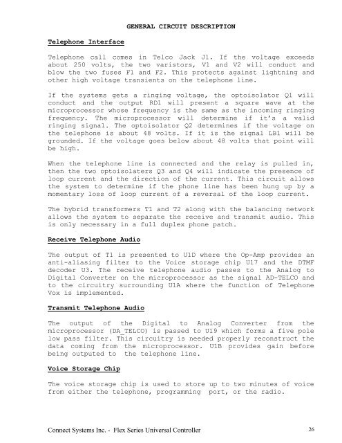
GENERAL CIRCUIT DESCRIPTION<br />
Telephone Interface<br />
Telephone call comes in Telco Jack J1. If the voltage exceeds<br />
about 250 volts, the two varistors, V1 and V2 will conduct and<br />
blow the two fuses F1 and F2. This protects against lightning and<br />
other high voltage transients on the telephone line.<br />
If the <strong>systems</strong> gets a ringing voltage, the optoisolator Q1 will<br />
conduct and the output RD1 will present a square wave at the<br />
microprocessor whose frequency is the same as the incoming ringing<br />
frequency. The microprocessor will determine if it’s a valid<br />
ringing signal. The optoisolator Q2 determines if the voltage on<br />
the telephone is about 48 volts. If it is the signal LB1 will be<br />
grounded. If the voltage goes below about 48 volts that point will<br />
be high.<br />
When the telephone line is <strong>connect</strong>ed and the relay is pulled in,<br />
then the two optoisolaters Q3 and Q4 will indicate the presence of<br />
loop current and the direction of the current. This circuit allows<br />
the system to determine if the phone line has been hung up by a<br />
momentary loss of loop current of a reversal of the loop current.<br />
The hybrid transformers T1 and T2 along with the balancing network<br />
allows the system to separate the receive and transmit audio. This<br />
is only necessary in a full duplex phone patch.<br />
Receive Telephone Audio<br />
The output of T1 is presented to U1D where the Op-Amp provides an<br />
anti-aliasing filter to the Voice storage chip U17 and the DTMF<br />
decoder U3. The receive telephone audio passes to the Analog to<br />
Digital Converter on the microprocessor as the signal AD-TELCO and<br />
to the circuitry surrounding U1A where the function of Telephone<br />
Vox is implemented.<br />
Transmit Telephone Audio<br />
The output of the Digital to Analog Converter from the<br />
microprocessor (DA_TELCO) is passed to U19 which forms a five pole<br />
low pass filter. This circuitry is needed properly reconstruct the<br />
data coming from the microprocessor. U1B provides gain before<br />
being outputed to the telephone line.<br />
Voice Storage Chip<br />
The voice storage chip is used to store up to two minutes of voice<br />
from either the telephone, programming port, or the radio.<br />
Connect Systems Inc. - Flex Series Universal Controller 26